
COMBINATIONAL LOGIC CIRCUIT
First Class
1
Dr. AMMAR ABDUL-HAMED KHADER

BASIC ADDER
• Adders are important in computers and also in other types of
digital system in which numerical data are processed. An
understanding of the basic operation is fundamental to the
study of digital system.
• There are two types of adder:
Half-Adder
Full-Adder
2
Dr. AMMAR ABDUL-HAMED KHADER
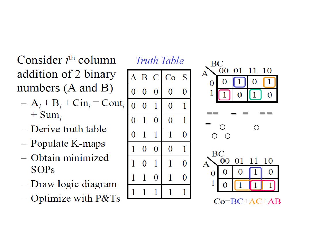
Adder
3
Dr. AMMAR ABDUL-HAMED KHADER
S=
ABC
+
ABC
+
ABC
+
ABC
=A(B + C)+A(B +C)
= A+ B +C
Adder
4
Dr. AMMAR ABDUL-HAMED KHADER

Half-Adder
• Recall the basic rules for binary addition:
0 + 0 = 0
0 + 1 = 1
1 + 0 = 1
1 + 1 = 10
• The operation are performed by a logic circuit called a Half-Adder.
It accepts two binary digits on its inputs and produces two binary
digits on its outputs, a sum bit and a carry bit.
A Sum
B Carry
INPUT OUTPUT
5
Dr. AMMAR ABDUL-HAMED KHADER
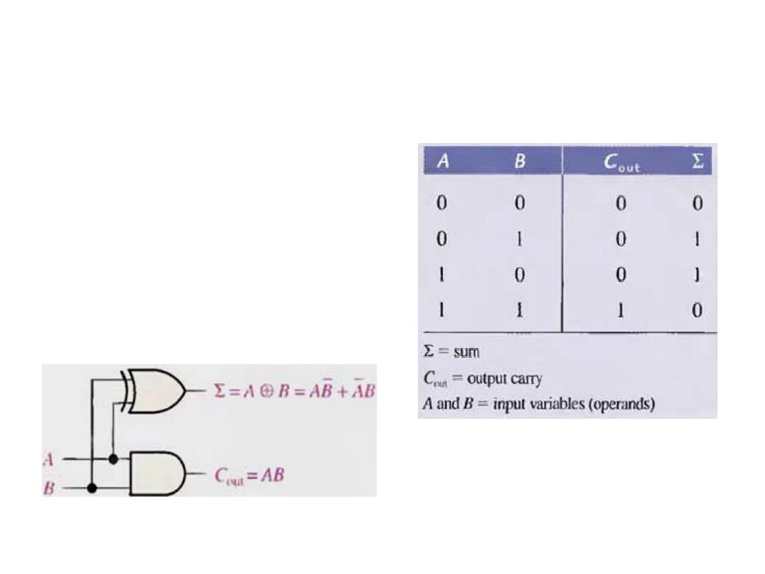
The Half-Adder
We can observe that the sum
is 1 only if the inputs are
not equal. Therefore the
sum can be expressed as the
exclusive OR of the input
variables.
6
Dr. AMMAR ABDUL-HAMED KHADER
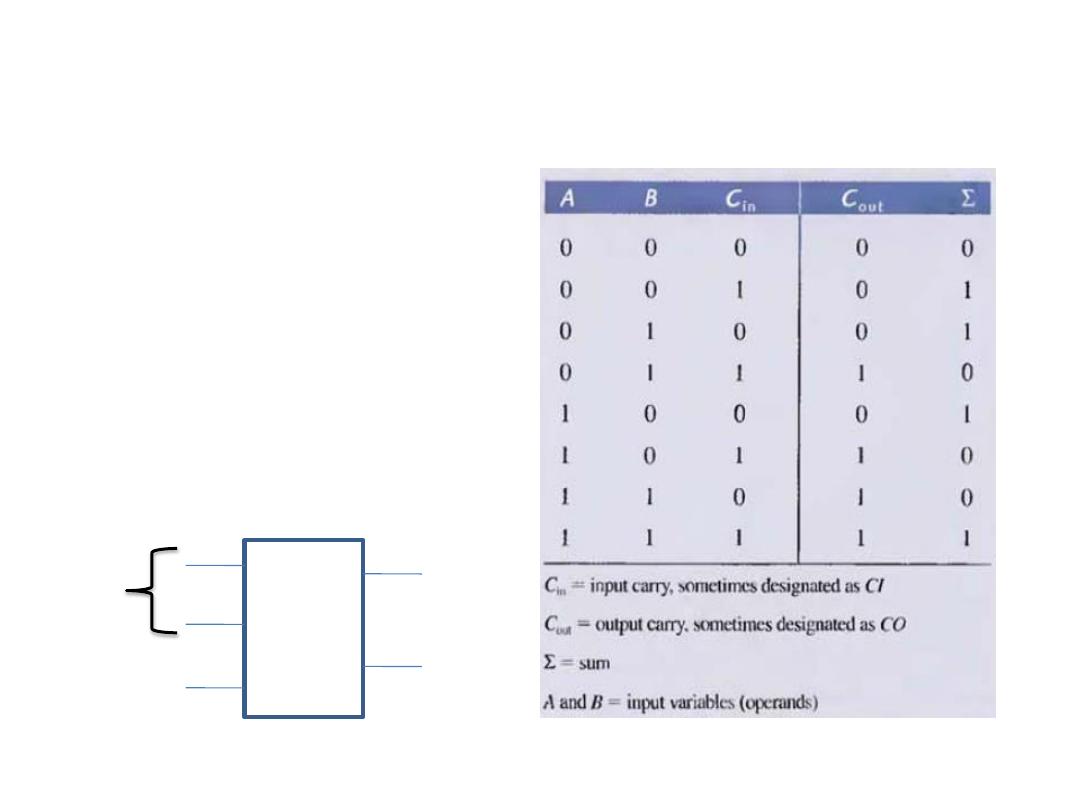
The Full-Adder
The full-adder accept two
input bits and an input carry
and generates a sum output
and an output carry.
The difference between Full
& Half-Adder is that the full-
adder accepts an input carry.
A Sum
B
C
out
C
in
INPUT OUTPUT
Carry output
carry
7
Dr. AMMAR ABDUL-HAMED KHADER
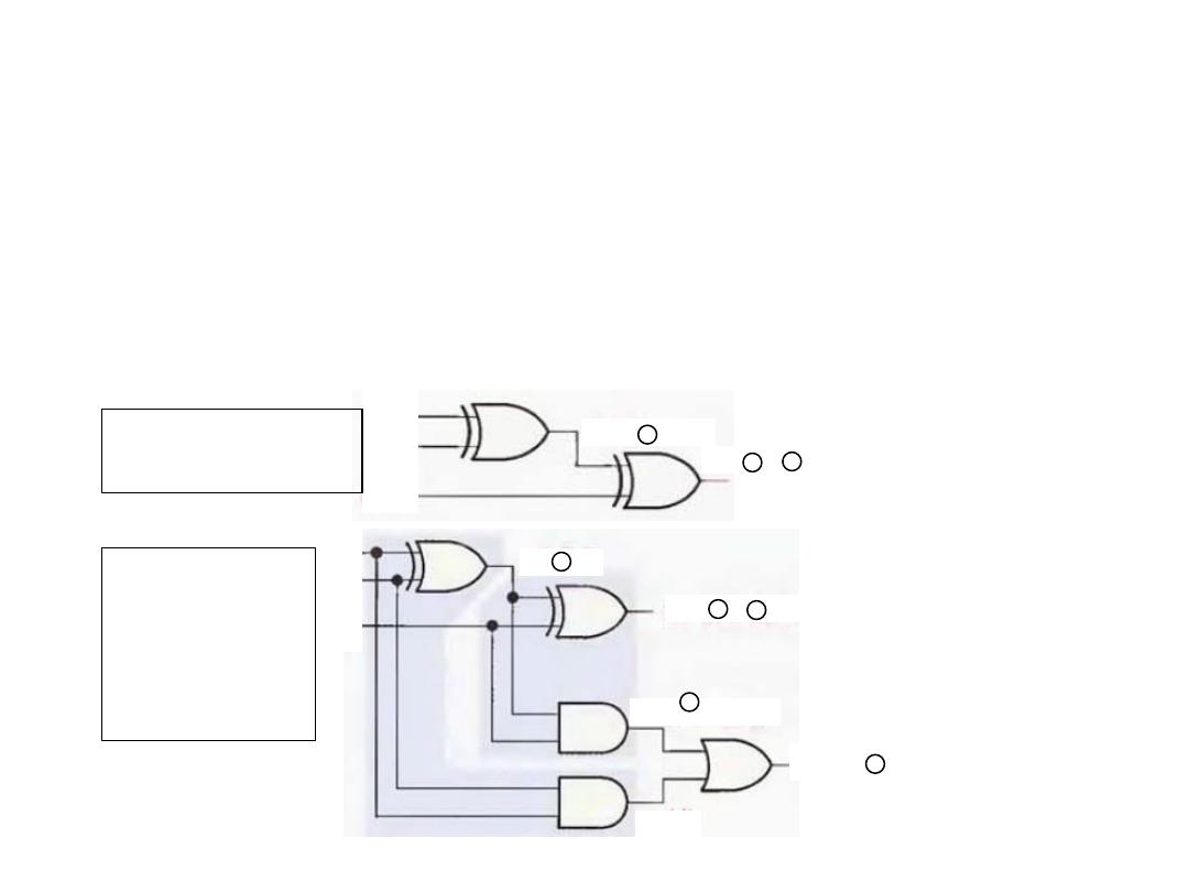
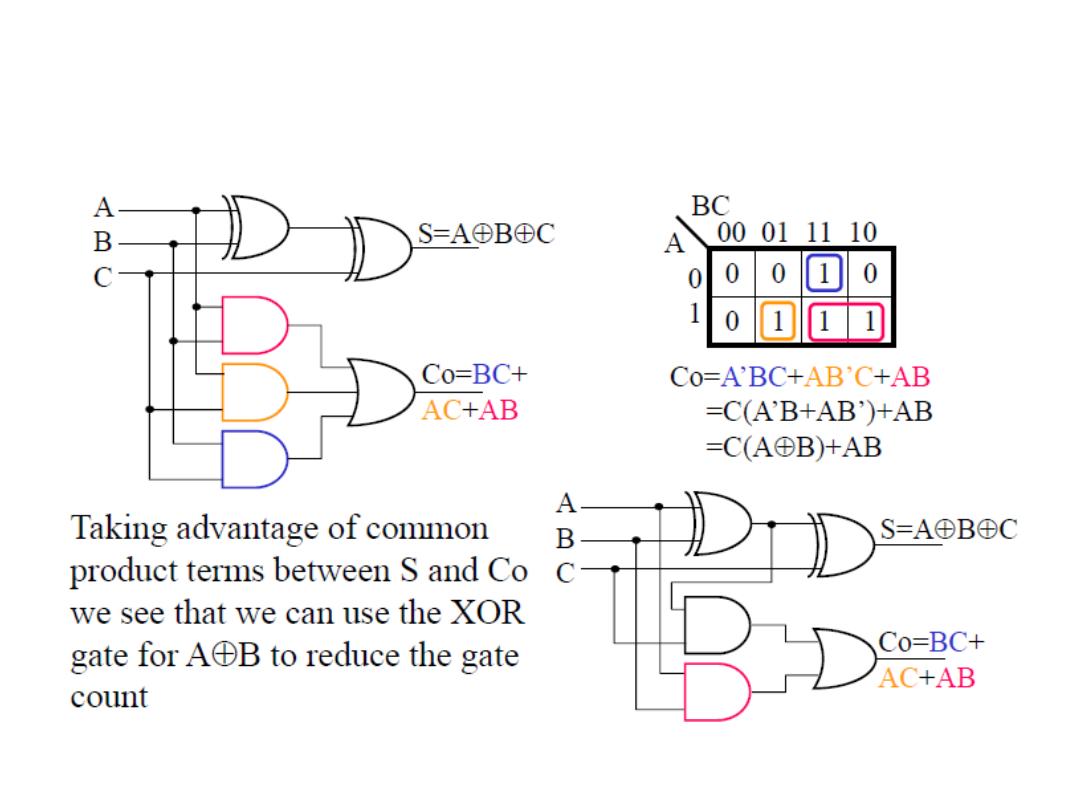
The Full-Adder
• After A exclusive-OR with B, C
in
must be exclusive-ORed
with their result. This means, that to implement the full-adder
sum function, two 2-inputs exclusive-OR gates can be used
A
B
C
in
A
+
B
A
+
B
+
C
in
A + B + C
in
A + B
A
B
C
in
(A
+
B) C
in
A
B
AB (A
+
B) C
in
Gates required for
one Full-Adder
Gates required
for Two Half-
Adder to
complete one
Full-Adder
8
Dr. AMMAR ABDUL-HAMED KHADER
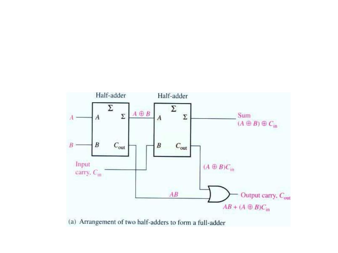
The Full-Adder
• The full adder circuit can be constructed from two half adder
circuits as shown
9
Dr. AMMAR ABDUL-HAMED KHADER
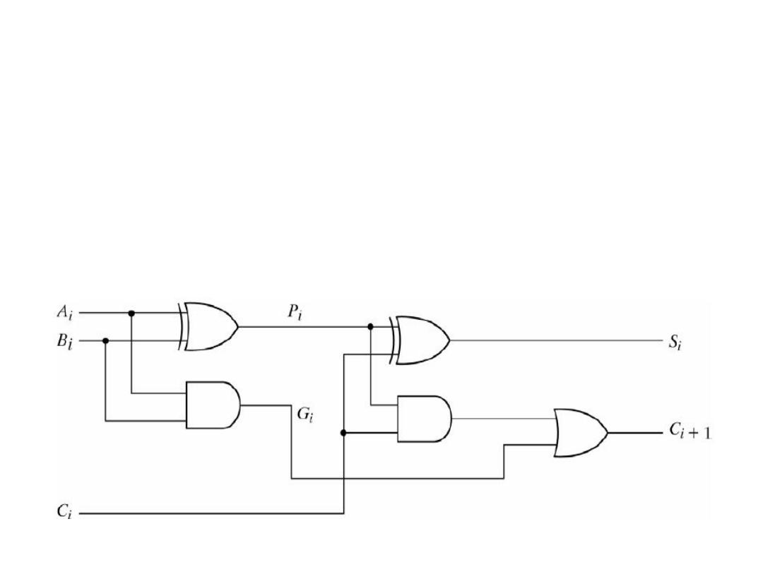
The Full-Adder
• P
i
= A
i
⊕B
i
• G
i
= A
i
B
i
• sum S
i
= P
i
⊕C
i
• carry C
i
+1 = G
i
+ P
i
C
i
10
Dr. AMMAR ABDUL-HAMED KHADER
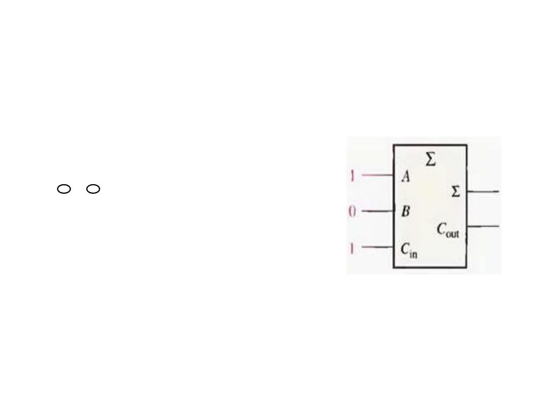
The Full-Adder
• Example: Determine the output for this full-adder:
Solution:
A (X-OR) B (X-OR) C
in
=
1 + 0 + 1 = 0 with a carry of 1
11
Dr. AMMAR ABDUL-HAMED KHADER
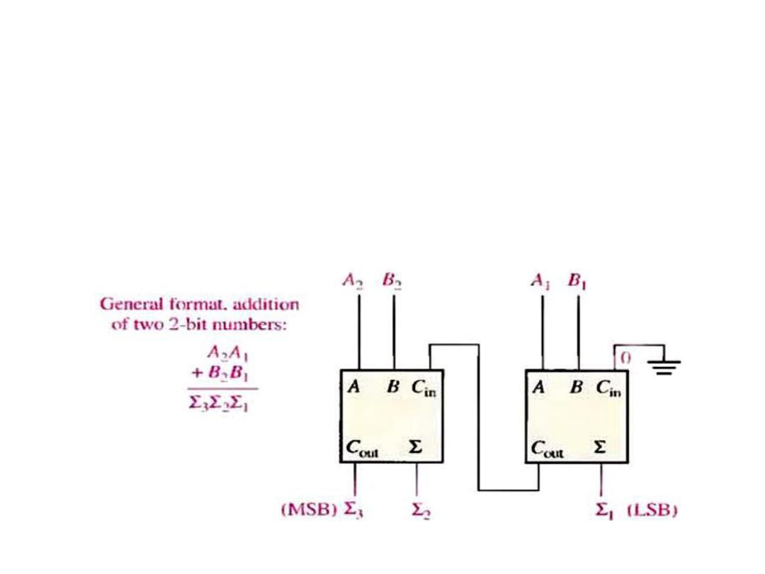
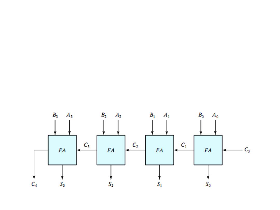
Parallel Binary Adder
Two or more full-adder are connected to form parallel binary
adder. To add two binary numbers, a full-adder is required for
each bit in the numbers. So for 2-bit numbers, two adders are
needed; for 4-bit numbers, four adder are used and so on.
12
Dr. AMMAR ABDUL-HAMED KHADER
Parallel Binary Adder
• Example: Determine the sum generated by the 3-bit parallel
adder, and show the intermediate carriers when the binary
numbers
101
and
011
are being added.
1
0
0
1
1
1
0
1
1
0
0
1
0
13
Dr. AMMAR ABDUL-HAMED KHADER
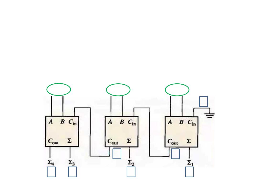
Parallel Binary Adder
• Example: Determine the sum generated by the 4-bit parallel
adder,
1011
A
i
,
0011
B
i
,
Solution:
0110 C
i
, 1110 S
i
, 0011 C
i+1
0
1
0
0
1
1
1
1
0 1 1 1 0
0 1 1 0
14
Dr. AMMAR ABDUL-HAMED KHADER
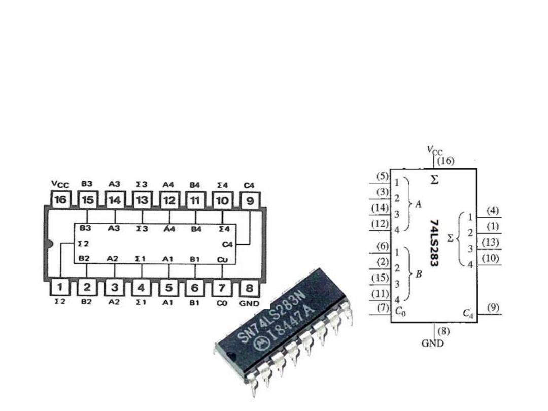
4-Bit Parallel Adder
• The 74LS283 IC (Integrated Circuit) is an example of 4-bit
parallel adder. The pin diagram and logic symbol for this IC is
shown below.
Dr. AMMAR ABDUL-HAMED KHADER
15
Pin diagram
Logic symbol
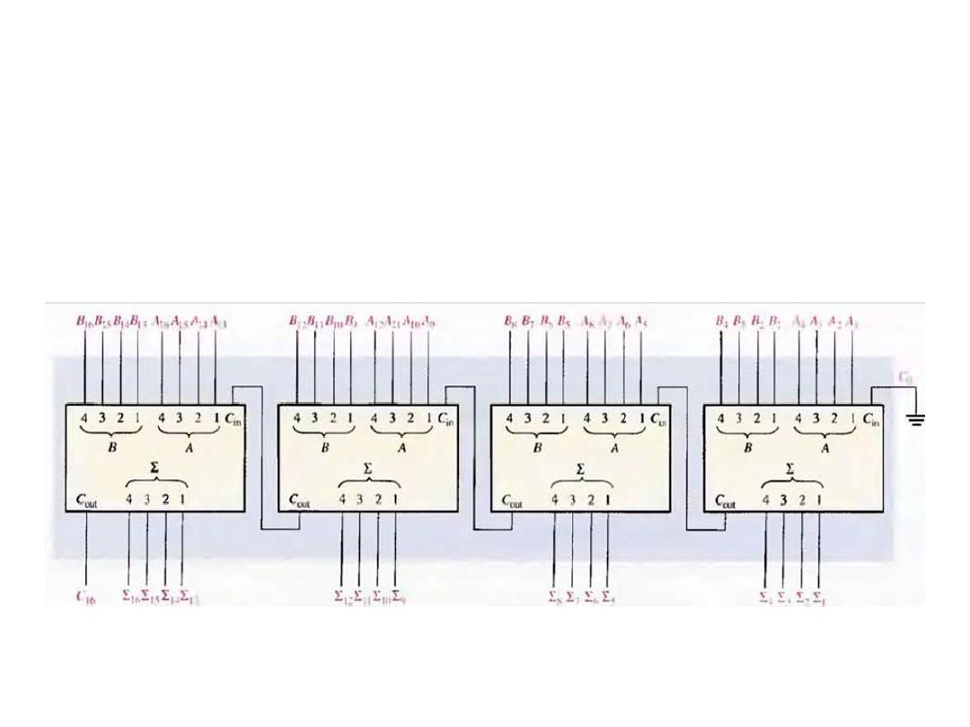
Adder Expanding
• Cascading of four 4-bit adders to form a 16-bit adder
Dr. AMMAR ABDUL-HAMED KHADER
16

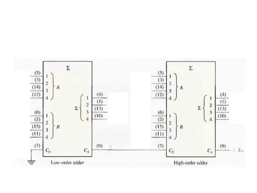
Adder Expanding
• Example: Show how two 74LS283 adders can be connected to
form an 8-bit parallel adders. Show output bits for the
following 8-bit input numbers.
A
8
……..A
1
= 10111001 and B
8
…….B
1
= 10011110
Solution: The only connection between the two ICs is the carry
output (pin9) of the lower order to the carry input (pin7) of
the high-order adder, pin7 of the lower-order adder is
grounded (no carry input) .
The total sum is:101010111
Dr. AMMAR ABDUL-HAMED KHADER
17
Adder Expanding
Dr. AMMAR ABDUL-HAMED KHADER
18
A
1
1
A
2
0
A
3
0
A
4
1
B
1
0
B
2
1
B
3
1
B
4
1
0
A
5
1
A
6
1
A
7
0
A
7
1
B
5
1
B
6
0
B
7
0
B
8
1
1
∑
1
∑
2
∑
∑
∑
5
∑
6
∑
∑

Subtractors
• The subtraction of two binary numbers may be accomplished
by taking the complement of the subtrahend and adding it to
the minuend. By this method, the subtraction operation
becomes an addition operation requiring full adders for its
machine implementation. It is possible to implement
subtraction with logic circuits in a direct manner. By this
method, each subtrahend bit of the number is subtracted from
its corresponding significant minuend bit to form a different
bit. If the minuend bit is smaller than the subtrahend bit, a 1 is
borrowed from the next significant position. The fact that a 1
has been borrowed must be conveyed to the next higher pair of
bits by means of a binary signal coming out (output) of a given
stage and going into (input) the next higher stage.
Dr. AMMAR ABDUL-HAMED KHADER
19

Subtractors
123
(A) or X
(Minuend)
– 78
(B) or Y
(Subtrahend)
45
DIFFERENCE
Dr. AMMAR ABDUL-HAMED KHADER
20
Example: Subtract the decimal number (78) from (123)
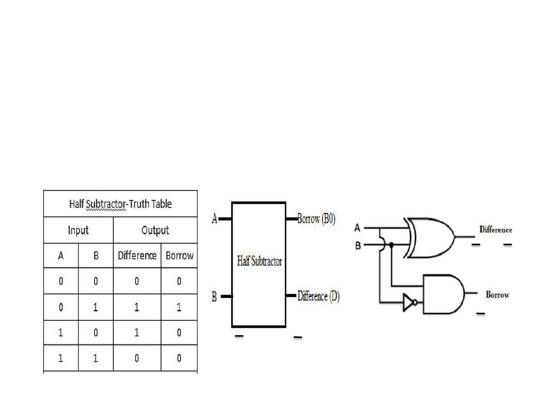
Half Subtractor
• The half-subtractor is a combinational circuit which is used to
perform subtraction of two bits. It has two inputs, A (minuend)
and B (subtrahend) and two outputs D (difference) and B
(borrow).
Dr. AMMAR ABDUL-HAMED KHADER
21
B0=AB D=A + B
B0=AB D=A + B
AB+AB
AB
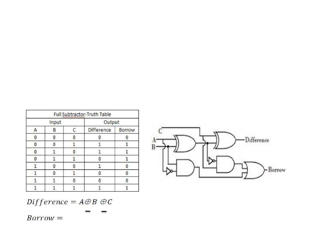
Full Subtractor
• The full-subtractor is a combinational circuit which is used to
perform subtraction of three bits. It has three inputs, A
(minuend) and B (subtrahend) and C (subtrahend) and two
outputs D (difference) and B (borrow)
Dr. AMMAR ABDUL-HAMED KHADER
22
AC + AB + BC
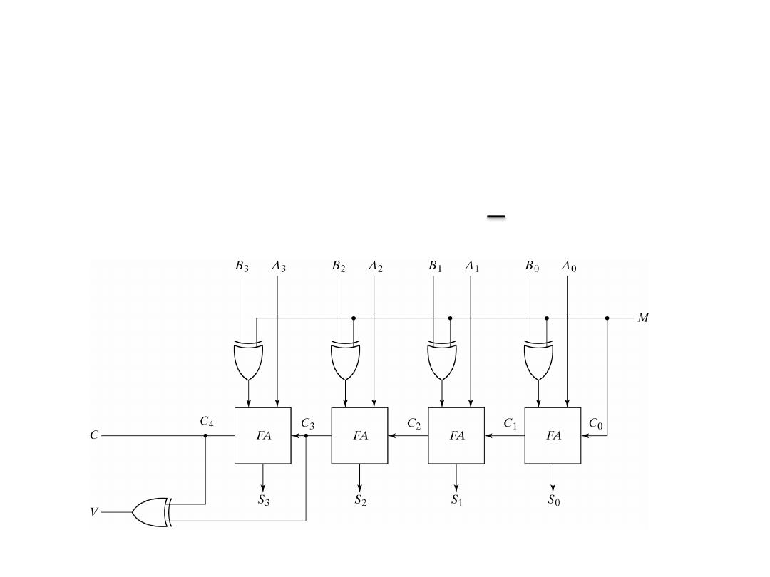
Adder-Subtractor
• 4-Bit Adder Subtractor
• M=0, the circuit is an adder (B⊕0 = B)
• M=1, the circuit is a subtractor (B⊕1 = B, C0=1)
Dr. AMMAR ABDUL-HAMED KHADER
23
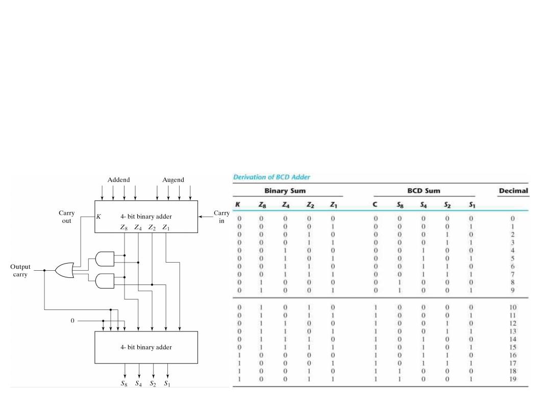
Decimal Adder
• Can be designed from 2 4-bit adder and external gates. So the two binary
numbers are added normally with external circuit that generates the carry
bit C when K+Z
8
Z
4
+Z
8
Z
2
=1.
• When Binary sum is greater than 9 a correction factor=(0110)b should be
added i.e. under the condition that Output carry =1
Dr. AMMAR ABDUL-HAMED KHADER
24
BCD adder
block diagram