Engineering mechanics
"Static"
lecture 1
Force System
Before dealing with a group or system of forces, it is necessary to examine the properties of a
single force in some detail, A force has been define as an action of one body on another. In dynamics we
will see that a force is defined as an action which tends to cause acceleration of a body. A force is a
vector quantity, because its effect depends on the direction as well as on the magnitude of the action.
Thus, the forces may be combined according to the parallelogram taw of vector addition.
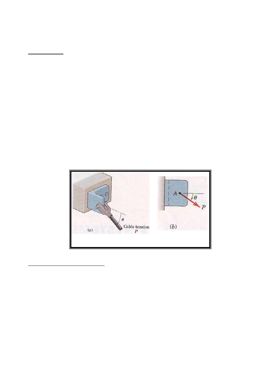
The action of the cable tension on the bracket in Fig.1a is represented in the side view,.Fig.2b, by the
force vector P of magnitude P. The effect of this action on the bracket depends on P, the angle θ, and the
location of the point of application A. changing any one of these three specifications will alter the effect
on the bracket, such as the forces in one of the bolts which secure the bracket to the base, or the internal
the complete specification of the action of a force must include its magnitude, direction, and point
application, and therefore we must treat it as a fixed vector.
1
External and internal Effects
We can separate the action of a force on a body into two effects, External and internal , for the
bracket of Fig.2 the effects of P external to the bracket are the reactive forces(not shown) exerted on the
bracket by the foundation and bolts because of the action of P. forces external to a body can be either
applied. forces or reactive forces. The effects of P internal to the bracket are the resulting internal forces
and deformations distributed throughout the material of the bracket. The rotation between internal forces
and internal deformations depends on the material properties of the body and is studied in strength of
materials, elasticity, and plasticity.
Figure 1
Principle of transmissibility
When dealing with the mechanics of a rigid body, we ignore deformations in the body and
concern ourselves with only the net external effects of external forces. In such cases, experience shows us
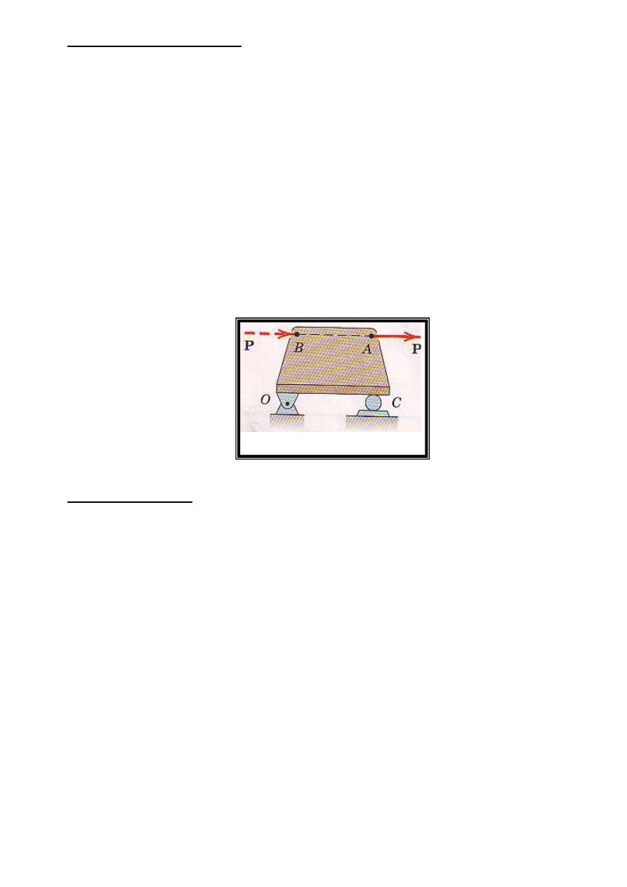
that it is not necessary to restrict the action of an applied force to a given point. For example, the force P
action on the rigid plate in Fig.2 may be applied at A or at B or at any other point on its line of action,
and the net external effects of P on the bracket will not change. The external effect are the force exerted
on the plate by the bearing support at 0 and the force exerted on the plate by the roller support at C.
This conclusion is summarized by the principle of transmissibility, which states that a force may be
applied at any point on its given line of action without altering the resultant effects of the force external to
the rigid body on which it acts. Thus, whenever we are interested in only the resultant external effects of
force, the force may be treated as a sliding vector, and we need specify only the magnitude, direction, and
line of action of the force, and not its point of application.
Figure 2
Force Classification
Forces are classified as either contact or body forces. A contact force Is produced by direct
physical contact; an example is the force exerted on a body a supporting surface. On the other hand, a
body force is generated by virtue of the position of a body within a force field such as A gravitational,
electric, or magnetic field. An example of a body force is your weight.
Forces may be further classified as either concentrated or distributed. Every contact force is
actually applied over a finite area and is therefore really a distributed force However, when the
dimensions of the area are very small compared with the other dimensions of the body, we may consider
the force to be concentrated at a point with negligible loss of accuracy. Force can be distributed over an
area as in the case of mechanical contact, over a volume when a body force such as weight is acting or
over a line, as in the case of the weight of a suspended cable.
The weight of a body is the force of gravitational attraction distributed over its volume and may be taken
as a concentrated force acting through the center of gravity. The position of the center of gravity is
frequently obvious if the body is symmetric.
We can measure a force either by comparison with other known forces, using a mechanical
balance, or by the calibrated movement of an elastic element. AIl such comparisons or calibrations have
2
as their basis a primary standard. The standard unit of force in SI units is the Newton (N) and in the U.S.
customary system is the pound (lb).
action and Reaction
According to Newton's third law, the action of a force is always accompanied by an equal and
apposite reaction. It is essential to distinguish between the action and the reaction in a pair of forces. To
do so, we first isolate the body in question and then identify the force exerted on that body (not the force
exerted by the body). It is very easy to mistakenly use the wrong force of the pair unless we distinguish
carefully between action and reaction.
Concurrent Forces
Two or more forces are said to be concurrent at a point if their lines of action intersect at that
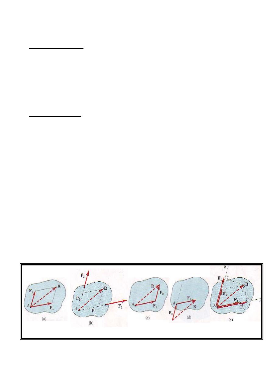
point. The forces F1 and F2 shown in Fig.3a have a common point of application and are concurrent at
the point A. Thus, they can he added using the parallelogram law in their common plane to obtain their
sum or resultant R, as shown in Fig. 3a. The resultant lies in the same plane as Fl and F2.
Suppose the two concurrent forces lie in the same plane but are applied at two different points as in Fig.
3b. By the principle of transmissibility, we may move them along their lines of action and complete their
vector sum R at the point of concurrent A, as shown in Fig. 3b. We can replace F1 and F2 with the
resultant R without altering the external effects on the body upon which they act.
We can also use the triangle law to obtain R, but we need to move
the line of action of one of the forces, as
shown in Fig.3c. If we add the same two forces, as shown in Fig. 3d, we correctly preserve the
magnitude and direction of R, but we lose the correct line of action, because R obtained in this way does
not pass through A. Therefore this two of combination should be avoided.
We can express the sum of the two forces mathematically by the vector equation
R=F1+F2
Figure 3
3
Vector Components
In addition to combining forces to obtain their resultant, we often need to replace a force by its
vector components in directions which are convenient for a given application. The vector sum of the
components must equal the original vector. Thus, the force R in Fig. 3a may be replaced by, or .resolved
into, two vector components F1 and F2 with the specified directions by completing the parallelogram as
shown to obtain the magnitudes of F1and F2.
The relationship between a force and its vector components along given axes must not be
contused with the relationship between a force and its perpendicular projections onto the same axes.
Fig.3e shows the perpendicular projections Fa and Fb of the given force R onto axes a and b, which are
parallel to the vector components F1 and F2 of Fig.3a. Figure 3e shows that the components of a vector
are not necessarily equal to the projections of the vector onto the same axes. Furthermore, the vector sum
of the projections Fa and Fb is not the vector R, because the parallelogram law of vector addition must be
used to form the sum. The components and projections of R are equal only when the axes a and b are
perpendicular.
A Special Case of Vector Addition
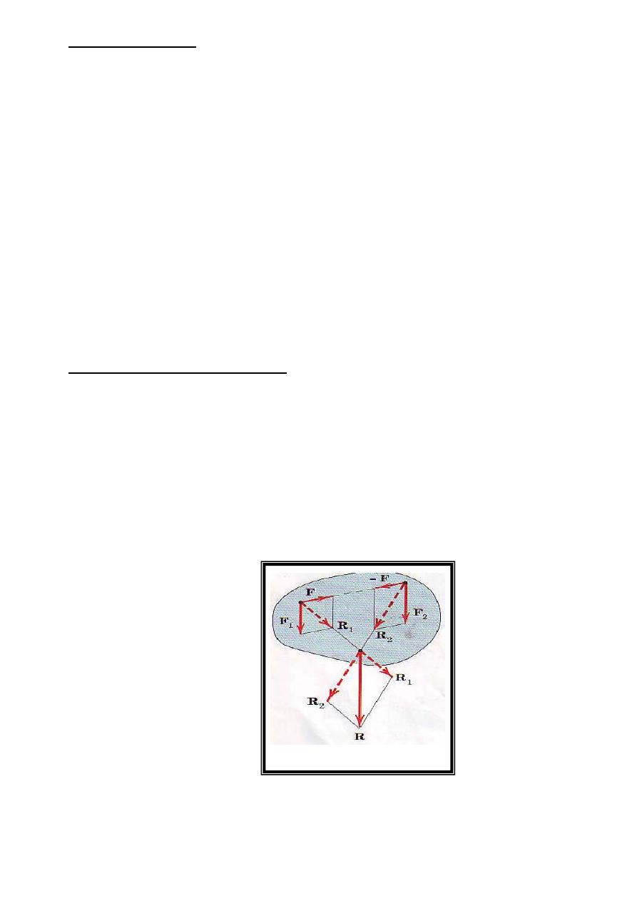
To obtain the resultant when the two forces Fl and F2 are parallel as in Fig. 4, we use a special
case of addition. The two vectors are combined by first adding two equal, opposite, and collinear forces F
and -F of convenient magnitude, which taken together produce no external effect on the body. adding F1
and F to produce R1 , and combining with the sum R2 of F2 and F yield the resultant R, which is correct
in magnitude, direction, and line of action. This procedure is also useful for graphically combining two
forces which have a remote and inconvenient point of concurrency because they are almost parallel.
Figure 4
4
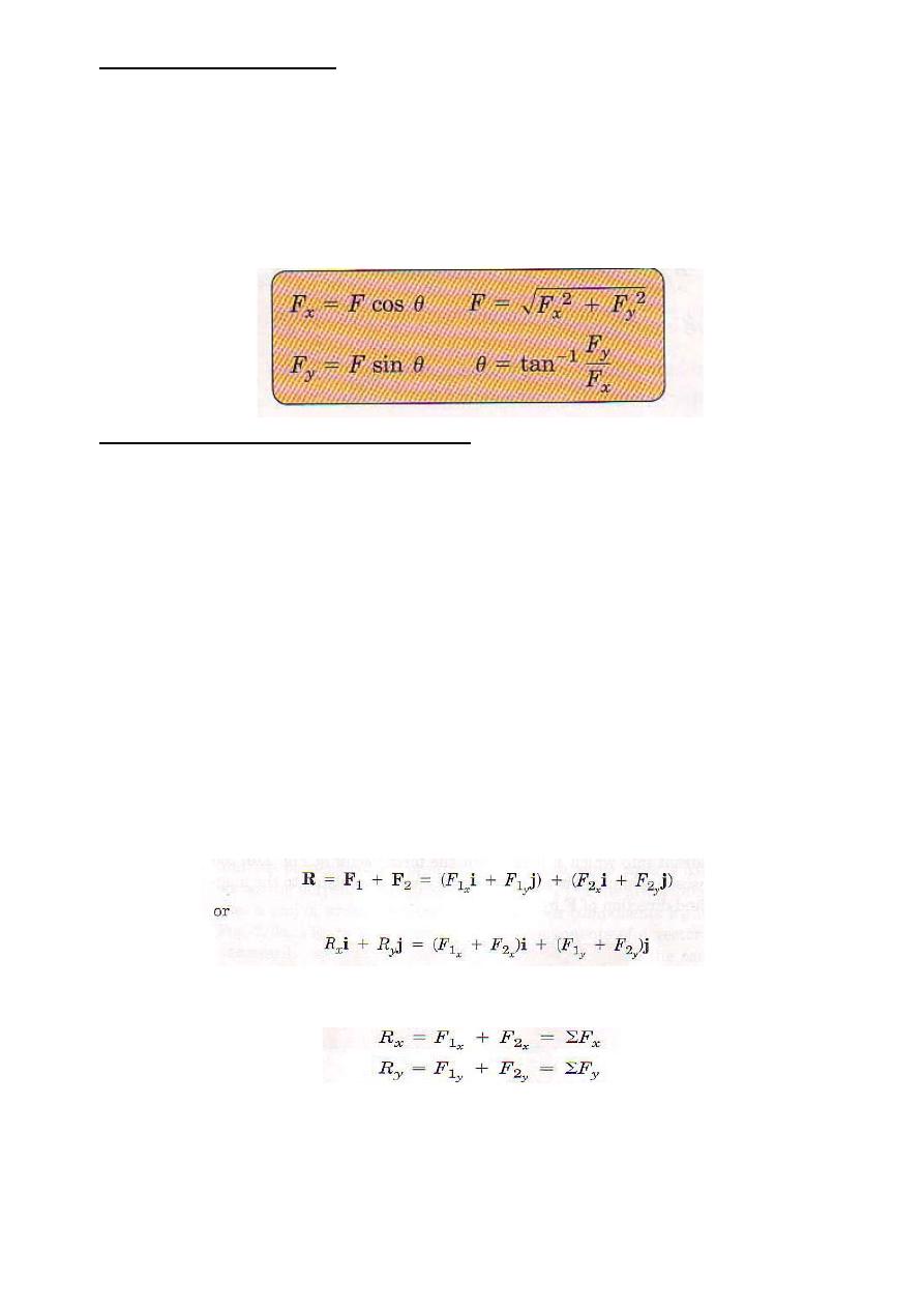
Rectangular Components
The most common two dimensional resolution of a force vector is into rectangular components. It follows
from the parallelogram rule that the vector F of Fig. 5 may be written as
F=Fx +Fy
Where Fx and Fy are vector components of F in the x- and y-direction.
For the force vector of Fig. 5, the x and y scalar components arc both positive and are related to the
magnitude and direction of F by
…... Eqs.1
Determining the Components of a Force
Dimensions
are not always given in horizontal and vertical directions, angles need not be measured
counterclockwise from the x-axis, and the origin of coordinate need not be on the line of action of a force.
Therefore, it is essential that we be able to determine the correct components of a force no matter how the
axes are oriented or how the angles are measured. Figure 6 suggests a few typical examples of vector
resolution in two dimensions.
Memorization of Eqs.1 is not a substitute for understanding the parallelogram law and for
correctly projecting a vector onto a reference axis. A neatly drawn sketch always he1p6 to clarify the
geometry and avoid error.
Rectangular components arc convenient for finding the sum or resultant R of two forces which are
concurrent. Consider two forces F1and F2 which are originally concurrent at a point O. Figure 7 shows
the line of action of F2 shifted from O to the tip of F1accoding to the triangles rule of Fig. 3 In adding the
force vectors F1 and F2, we may write
From which we conclude that
……2
5
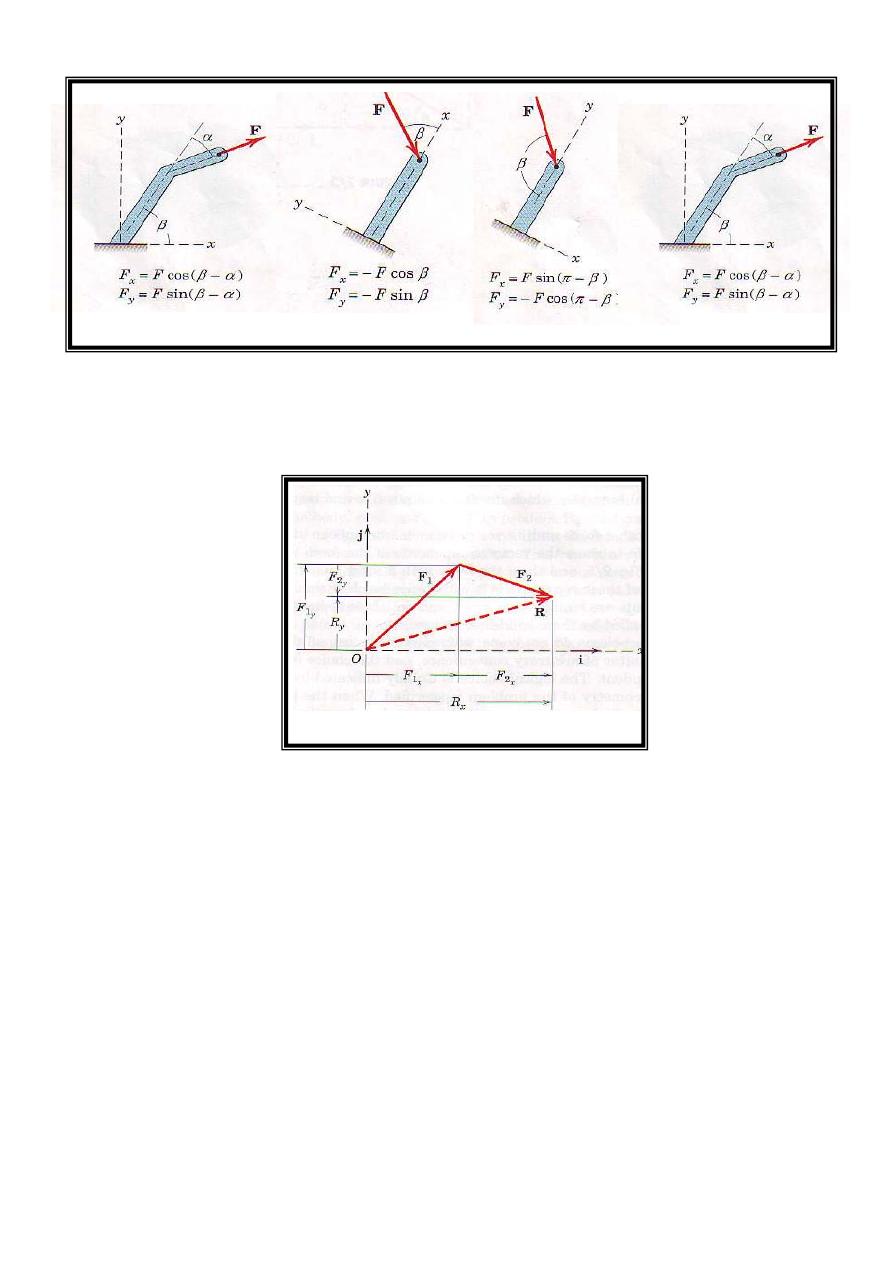
Figure 6
The term ΣFx means "the algebraic sum of the x scalar components". For" the example- shown In Fig. 7,
note that the scalar component F
2y
would be negative.
Figure 7
6
Examples
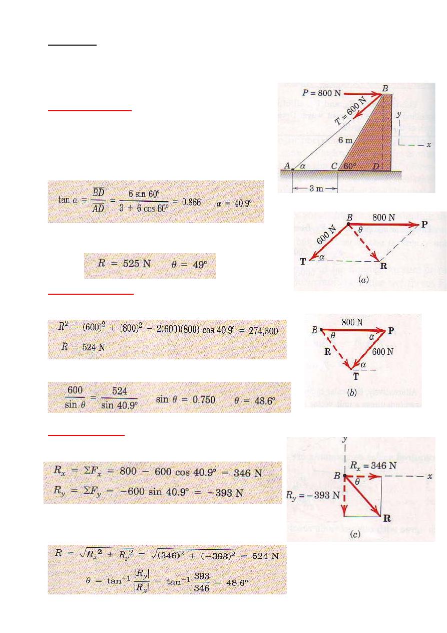
Example 1
Combine the two forces p and T, which act on the fixed structure at B, into a single equivalent force R.
Graphical solution
The parallogram for the vector addition of forces T and P is
constructed as shown in Fig.a . the approxmate scale used
here is 1cm=400n; a scale of 1cm = 100 N would be more
suitable for regular- size paper and would give greater
accuracy. Note that the angle α must be determined prior to
construction of the parallogram. From the given figure
Measurment of the length R and direction θ of the resultant force
R yield the approximate results
Geometric solution
The triangle for the vector addition of T and P is shown in Fig, b.
the angle α is calculated as above. The law of cosines gives
frome the law sines, we may determine the angle θ which orients R.
thuse,
Algebric solution
By using the x-y coordinate system on the given figure,
7
we may write
The magintude and direction of the resultant force R as shown
in Fig, c are then
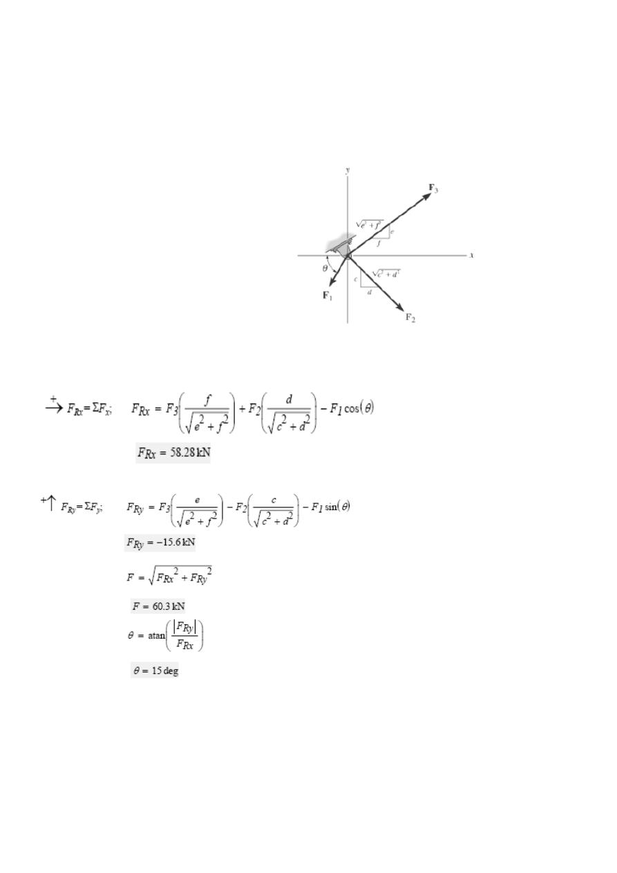
Examples 2:
Determine the magnitude of the resultant force and its direction measured clockwise from
the positive x axis.
Units Used:
kN = 10
3
N
Given:
F1 = 20 kN
F2 = 40 kN
F3 = 50 kN
θ = 60 deg
c = 1
d = 1
e = 3
f = 4
Solution:
8
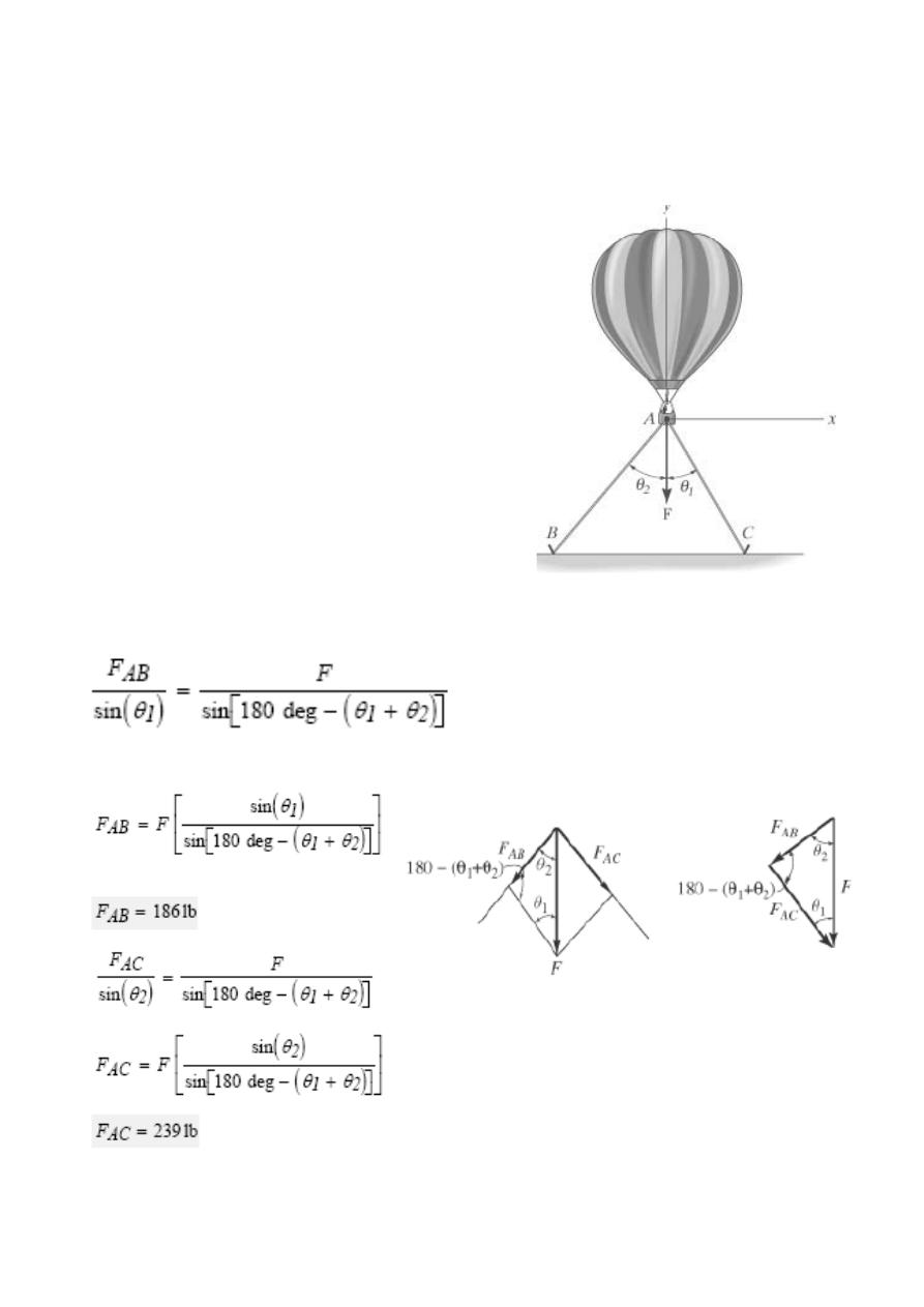
Example 3
A resultant force F is necessary to hold the ballon in place.
Resolve this force into components
along the tether lines AB and AC, and compute the magnitude of each component.
Given:
F = 350 lb
θ 1 = 30 deg
θ 2 = 40 deg
Solution:
9
Problems
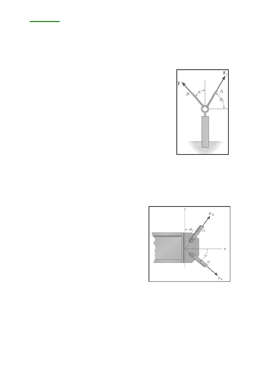
The post is to be pulled out of the ground using two ropes A and B. Rope A is subjected to force
F1 and is directed at angle θ1 from the horizontal. If the resultant force acting on the post is to be
FR, vertically upward, determine the force T in rope B and the corresponding angle θ.
Given:
FR = 1200 lb
F1 = 600 lb
θ1 = 60 deg
The plate is subjected to the forces acting on members A and B as shown. Determine the magnitude of the
resultant of these forces and its direction measured clockwise from the positive x axis. Given:
FA = 400 lb
FB = 500 lb
θ1 = 30 deg
θ = 60 deg
10
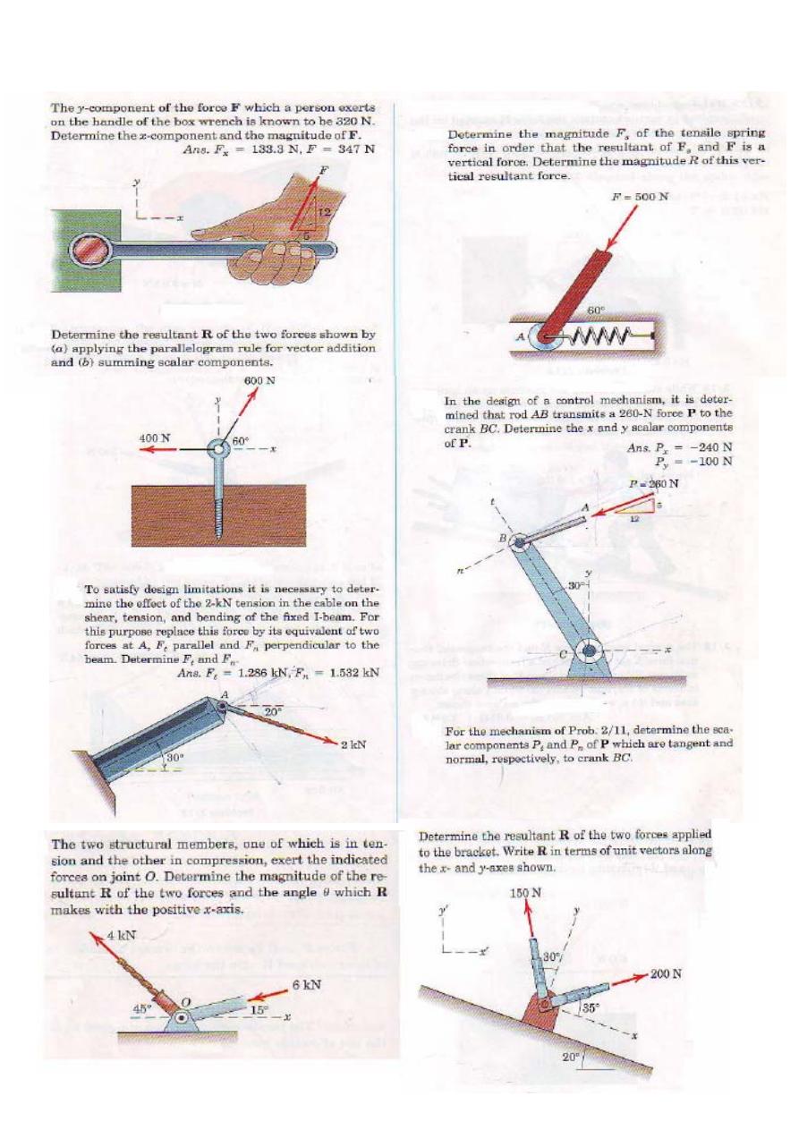
1/ The two structural members, one of which is in tension
and the other in compression, exert the indicated
forces on joint 0. Determine the magnitude of the resultant R of the two forces and the angle θ which R
makes with the positive x-axis.
11
12
Lecture 2
Moment
In addition to the tendency to move a body in the direction of its
application, a force can also tend to rotate a body about an axis. The
axis may be any line which neither intersects nor is parallel to the
tine of action of the force. This rotational tendency is known as the
moment M of the force. Moment is also refereed to as torque.
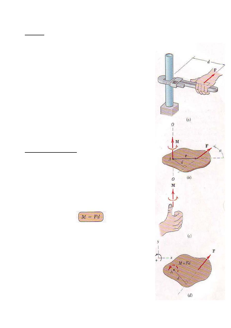
As a familiar example of the concept of moment, consider. the pipe
wench of Fig. a. One effect of the force applied perpendicular to the
handle of the wench is the tendency to rotate the pipe about its
vertical axis. The magnitude of this tendency depends on both the
magnitude F of the force and the effective length d of the wrench
handle. Common experience shows that a pull which is not
perpendicular to the wrench handle is less effective than the right-
angle pull shown.
Moment about a Point
Figure b shows a two-dimensional body acted on by a force F in its
plane. The magnitude of the moment or tendency of the force to
rotate the body about the axis O-O perpendicular to the plane of the
body is proportional both to the magnitude of the force and to the
moment arm d, which is the perpendicular distance from the axis to
the line of l action of the force. Therefore ,the magnitude of the
moment is defined as
The moment is a vector M perpendicular to the plane of the body.
The sense of M depends on the direction in which F tends to rotate
the body The right-hand rule, Fig.1c, is used to identify this sense.
We represent the moment of F about O-O as a vector pointing in
the direction of the thumb, with the finger curled in the direction of
the relational tendency.
The
moment M obeys all the rules of vector combination and may
be considered a sliding vector with a line of action coinciding with
the moment axis. The basic units of moment in SI units are
Newton-meters (N.m), and in the U.S. customary system are
pound-feet (ob-ft).
Figure 1
13

14
When dealings with forces which all act in a given plane, we customarily speak of the moment about a
point. By this we mean the moment with respect to an axis normal to the plane and passing through the
point. Thus, the moment of force F about point A in Fig.d has the magnitude M =Fd and is
counterclockwise.
Moment directions may be accounted for by using a stated sign convention. such as a plus sign (+) for
counterclockwise moment and a minus sign! (+) for clockwise moments, or vice versa. Sign consistency
within a given problem is essential. For the sign convention of Fig.d, the moment of F about point A (or
about the z-axis passing through point A) is positive. The curved arrow of the figure is a convenient way
to represent moments in two-dimensional analysis.
Varignon
,
s theorem
One of the useful principles of mechanics is Varignon
,
s theorem, which states that the moment of
a force about any point is equal to the sum of the moment of the components of the force about the same
point.
To prove this theorem, consider the force R acting in the plane of the body shown in Fig. 2a. The forces P
and Q represent any two nonrectangular components of R. The moment of R about point O is
M
o
=r
x
R
Because R=P + Q, we may write
r x R=r x (P+Q)
Using the distributive law for cross products, we have
M
o
=r
x
R= r x P+ r x Q …………
which says that the moment of R about O equals the sum of the moments about O of its components P
and Q. This proves the theorem.
Varignon's theorem need not be restricted to the case of two component, but it applies equally
well to three or more. Thus we could have used any number of concurrent components of R in the
foregoing proof
figure 2b illustrates the usefulness of Varignon's theorem. The moment of R about point O is Rd.
However, if d is more difficult to determine than p and q, we can resolve R into the components P and Q,
and compute the moment as
M
o
=Rd= -pP + qQ
where we take the clockwise moment sense to be positive. Sample Problem 1 shows how Varignon's
theorem can help us to calculate moments.
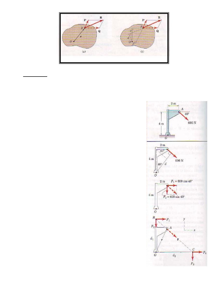
Figure 2
Examples
Example 1
Calculate the magnitude of the moment about the base point O of the 600N force in five different way
Solution
(I) The moment arm to the 600-N force is
d = 4 cos 40˚ + 2 sin 40˚ = 4.35 m
(1) By M = rd the moment is clockwise and his the magnitude
Mo = 600(4. 35) = 2610 N.m
(II) Replace the force by its rectangular components at A
F1= 600 cos 40˚ = 460 N, F2 = 600 sin 40˚= 386N
(2)By Varignon's theorem, the moment becomes
Mo = 460(4) + 386(2) = 2610N
(III) By the principle of transmissibility, move the 600-N force
along its line of action to point B, which eliminates the moment of
the component F2. The moment arm of F1 becomes
d1 = 4 + 2 tan 40˚ = 5.68 m
and the moment is
Mo = 460(5.68) = 2610 N.m
(3) (IV) Moving the force to point C eliminates the moment of the
component F1. The moment am of F2 becomes
d2 = 2 + 4 cos40˚ = 6.77 m
and the moment is
Mo = 386(6.77) + 2610 N.m
15
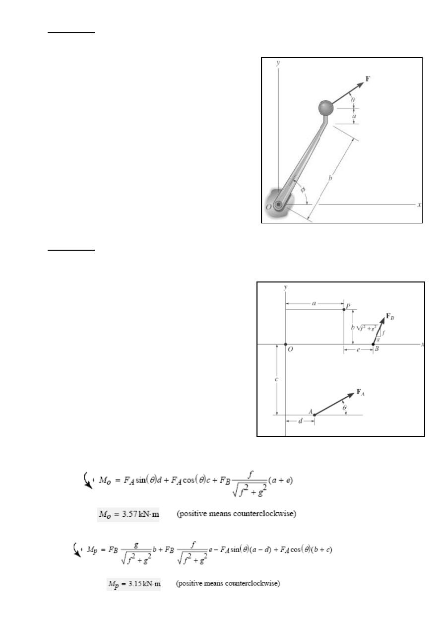
Example 2
Determine the angle θ (0 <= θ <= 90 deg) so that the force F develops a clockwise moment M
about point O.
Given:
F = 100 N φ = 60 deg
M 20 = N.m a = 50 mm
θ = 30 deg b = 300 mm
Solution:
Initial Guess θ = 30 deg
Given
M=Fcos(θ )(a+bsin(φ ))− F sin(θ )(b cos(φ ))
θ = Find(θ ) θ = 28.6 deg
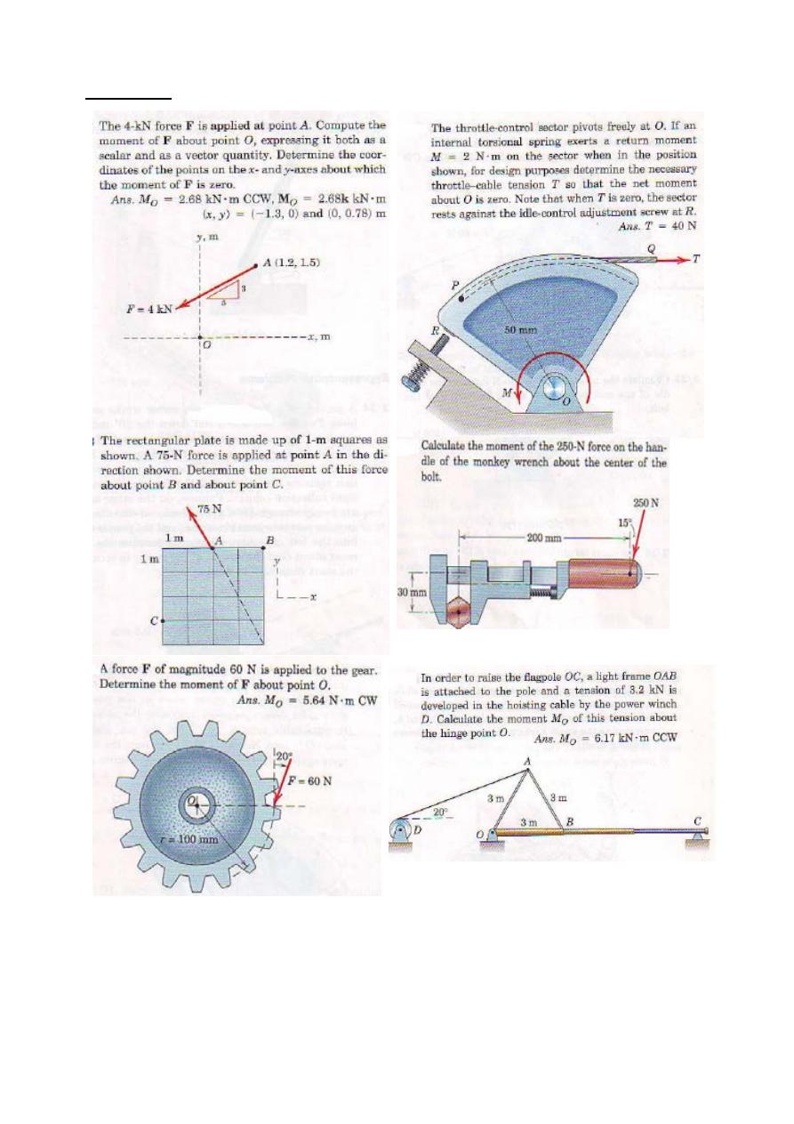
Example 3
Determine the magnitude and directional sense of the moment of the forces
(1) about point O.
(2)
about point P.
Given:
FB = 260 N e = 2 m
a = 4 m f = 12
b = 3 m g = 5
c = 5 m θ = 30 deg
d = 2 m FA = 400 N
Solution:
(1)
(2)
16
Problems
17
18
Lecture 3
Couples
The moment produced by two equal, opposite, and noncollinear forces is
called a couple. couples have certain unique properties and have important
applications in mechanics.
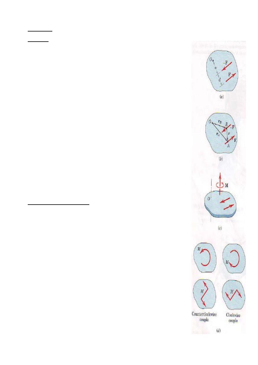
Consider the action of two equal and opposite forces F and -F a
distance d apart, as shown in lfig.1a . These two forces cannot be combined
into a single force because their sum in every direction is zero. Their only
effect is to produce a tendency of rotation. The combined moment of the
two forces about an axis normal to their plane and passing through any
point such as O in their plane is the couple M. This couple has a magnitude
M= F(a+b)-Fa
Or M= Fd
Its direction is counterclockwise when viewed from above for the case
Illustrate. Note especially that the magnitude of the couple is dependent of
the distance a which locates the forces with respect to the moment center 0.
lt follows that the moment of a couple has the same value for all moment
centers.
Vector Algebra Method
We may also express the moment of a couple by using vector algebra. With
the cross product Eq. the combined moment about point 0 of the couple of
Fig. 1b is
M = r
A
x F + r
B
x (-F) = (r
A
– r
B
) xF
where r
A
and r
B
are position vector which run from point O to arbitrary
points A and B on the tines of action of F and -F, respectively. Because r
A
-
r
B
= r, we can express M as
M = rx F
Here again, the moment expression contains no reference to the moment
center 0 and, therefore, is the same for all moment centers. Thus, we may
represent M by a free vector, as shown in Fig. 1c, where the direction of M
is normal to the plane of the couple and sense of M is established by the
right-hand rule.
Figure 1
19
Because the couple vector M is always perpendicular to the plane of the forces which constitute
the couple, in two dimensional analysis we can represent the sense of couple vector as clockwise or
counterclockwise by one of the convention shown in fig.1d. later, when we deal with couple vectors in
three-dimensional problems, we will make full use of vector notation to represent them, and the
mathematics will automatically account for their sense.
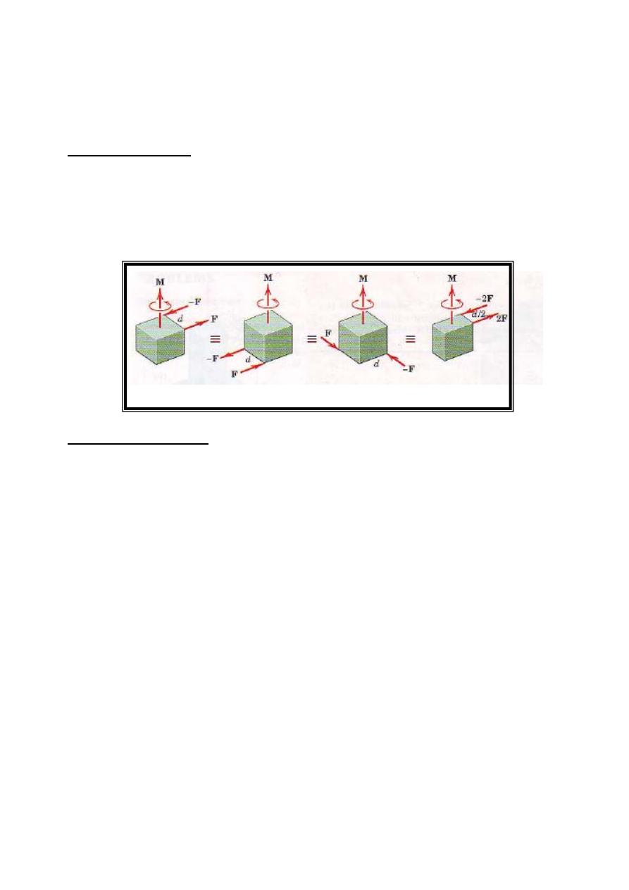
Equivalent Couples
Changing the values of F and d does not change a given couple as long as the product Fd remains the
same. Likewise, a couple is not affected if the forces act in a different but parallel plane. Figure 2 shows
four different configurations of the same couple M. In each of the four cases, the couples are equivalent
and are described by the same free vector which represents the identical tendencies to rotate the bodies.
Figure 2
Force-Couple Systems
The effect of a force acting on a body is the tendency to push or pull the body in the direction of
the force, and to rotate the body about any fixed axis which does not intersect the line of the force. We
can represent this dual effect more easily by replacing the given force by an equal parallel force and a
couple to compensate for the change in the moment of the force.
The replacement of a force by a force and a couple is illustrated in Fig. 3, where the given force F
acting at point A is replaced by an equal force F at some point B and the counterclockwise couple M =
Fd. The transfer is seen in the middle figure, where the equal and opposite forces F and -F are added at
point B without introducing any net external effects on the body. We now see that the original force at A
and the equal and opposite one at B constitute the couple M = Fd, which is counterclockwise for the
sample chosen, as shown in the right-hand part of the figure. Thus, we have replaced the original force at
A by the same force acting at a different point B and a couple, without altering the external effects of the
original force on the body. The combination of the force and couple in the right-hand part of Fig.3 is
referred to as a force-couple system.
By reversing this process, we can combine a given couple and a force which lies in the plane of
the couple (normal to the couple vector) to produce a single, equivalent force. Replacement of a force by
an equivalent force-couple system, and the reverse procedure, have many applications in mechanics and
should be mastered.
20
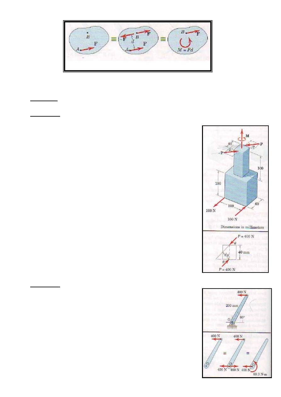
Figure 3
Examples
Example 1
The rigid structural member is subjected to a couple consisting of the two
100-N forces. Replace this couple by an equivalent couple consisting of
the two forces P and –P, each of which has a magnitude of 400 N.
Determine the proper angle θ.
Solution
The original couple is counterclockwise when the plane of the forces is
viewed from above, and its magnitude is
[M = F d]
M = 100(0.1) = 10 N.m
The forces P and –P produce a counterclockwise couple
M = 400(0.040)cosθ
Equating the two expression gives
10 = 400(0.040) cosθ
θ = cos (10/16) = 51.3˚
Example 2
21
Replace the horizontal 400-n force acting on the lever by an equivalent
system consisting of a force at O and a couple.
Solution
We apply two equal and opposite 400-N forces at o and identify
counterclockwise couple
[M = F d]
M = 400(0.200sin60˚ ) = 69.3 N.m
Thus, the original force is equivalent to the 400-n forces at 0 and the 69.3
N.m couple as shown in third of the three equivalent figures
22
23
24
25