- 1 -
CHAPTER TEN
FRICTION CLUTCHES
The word clutch is a generic term describing
any one wide variety of devices that is capable
of causing a machine or mechanism to become
engaged or disengaged. Clutches are of three
main types:
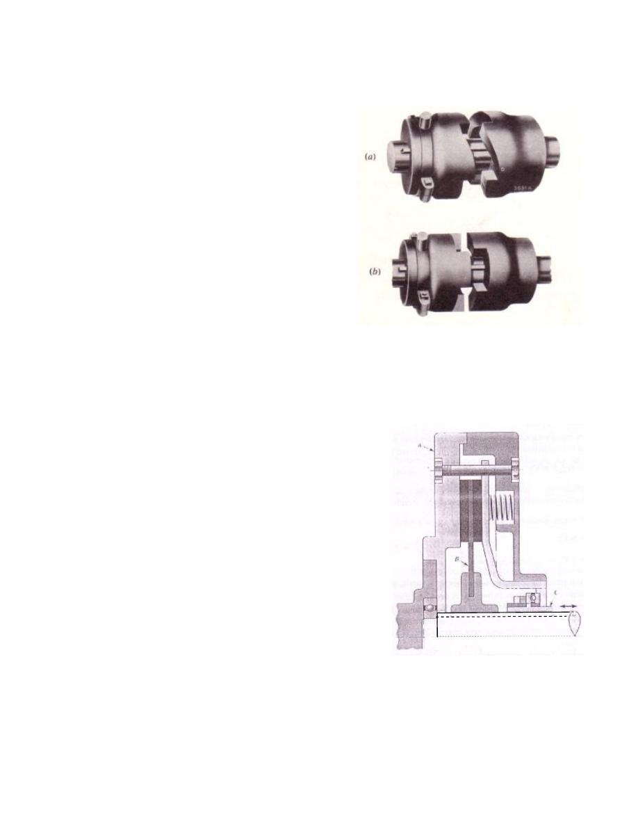
1. Positive or jaw clutches, Figure 10.1
2. Friction clutches
3. Hydraulic clutches
The friction clutches of the following types are
important from the subject point of view:
1. Disc or Plate Clutches
2. Cone clutches
3. Centrifugal clutches
10.1 Plate Clutches
In a plate clutch, the torque is transmitted by friction
between one or more pairs of co-axial annular faces
maintained in contact by axial thrust (force). Both
sides of each plate are normally effective, so that a
single-plate clutch has two pairs of surfaces in contact,
Figure 10.2
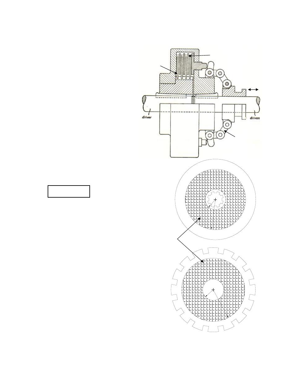
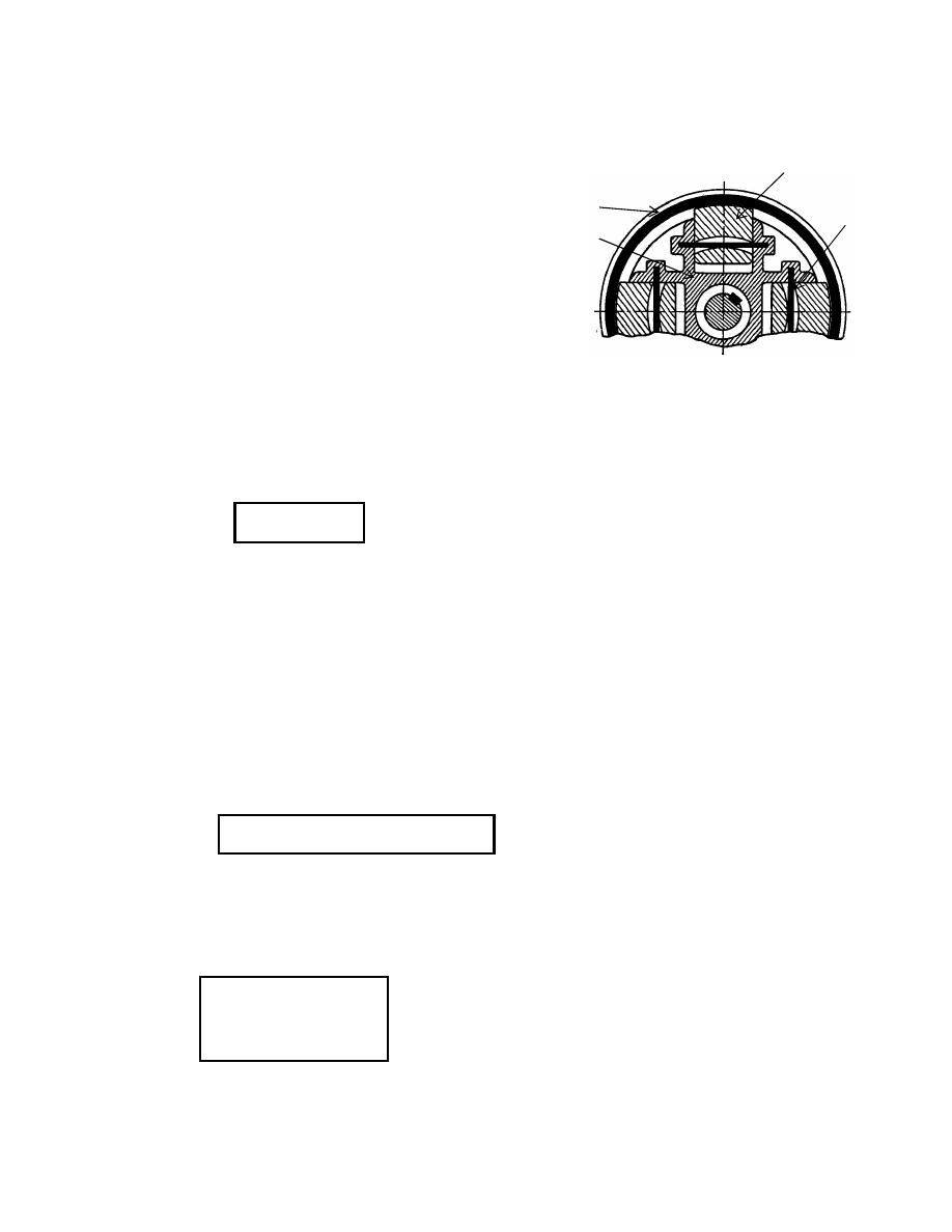
10.1.1 Construction
The basic components of plate clutch are, Figure 10.3:
1. inner plates: which are friction discs connected to the driving shaft so that they
are freely to slide axially in inner grooves, as shown in Figure 10.3b
Figure 10.1: Jaw clutches
Figure 10.2: Single-plate clutch
- 2 -
2. outer plates: which are friction discs connected to the driven shaft so that they
are freely to slide axially in outer grooves, as shown in Figure 10.3c
3. toggle mechanism: which is a
mechanism used to apply axial
thrust (force) on the plates, so that
they are maintained in contact
during engagement of the clutch
10.1.2 Number of pairs in contact (n)
If the outer and inner discs have two
sides of friction material (i.e. two
effective sides) then:
If n
1
= outer discs no., n
2
= inner discs no.
n
2
= n
1
+1
If n
1
= 3, n
2
= 4, n = 3 + 4 – 1 = 6 pairs
n = 2 pairs in single plate clutch
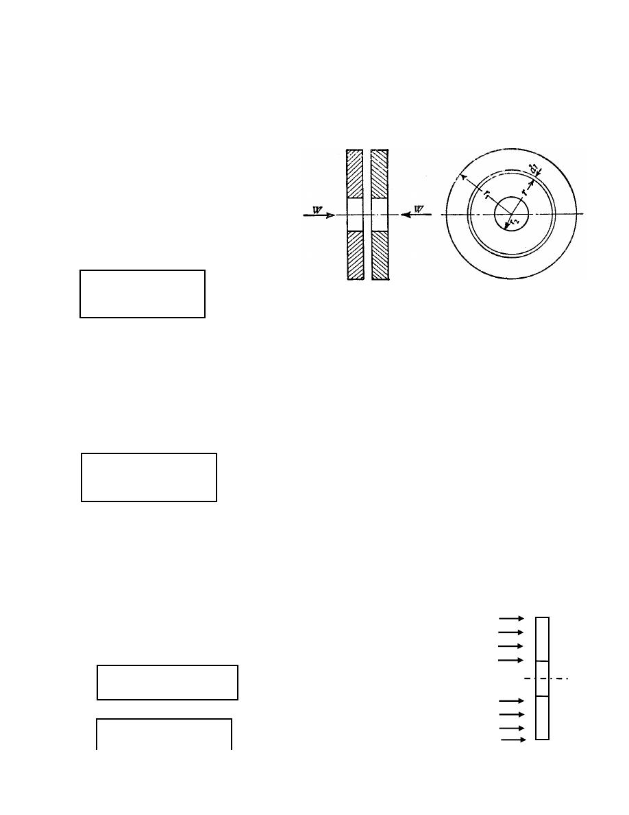
10.1.3 Maximum transmitted torque:
Let
r
1
, r
2
, R:
Outer, inner and mean radius of
friction faces in the disc
respectively.
W
Axial thrust (normal force between
friction faces of discs) applied by toggle
mechanism (by springs.
T
Maximum transmitted torque for no
slipping to be occurred.
Friction material
r
2
r
1
r
1
r
2
Toggle
mechanism
Inner disc
Outer disc
Inner disc
Outer disc
Figure 10.3: Plate clutch
(a)
(b)
(c)
n = n
1
+ n
2
-1
P
Pressure intensity between friction faces
during clutch engagement.
µ
Coefficient of friction of contact
Consider the ring element of one surface of contact:
The differential area of ring element is
dA = 2
π rdr
The differential normal force is
dW = 2
π P rdr
The total force:
The differential friction force is
dF
r
=
µ dW
Then the torque in the ring element is
dT = r dF
r
= 2
µ
P
π r
2
dr
The total maximum torque for no slipping is
10.1.4 Theories used in the analysis of Friction clutch
1. Uniform pressure theory
This theory is applicable for new clutches, in which the pressure intensity between
friction faces is assumed to be constant.
P = constant
∫
=
1
2
2
r
r
rdr
P
W
π
∫
=
1
2
r
r
2
dr
Pr
2π
T
µ
∫
=
∴
1
2
2
r
r
rdr
P
W
π
)
r
r
(
P
W
2
2
2
1
−
=
π
∫
=
1
r
r
2
dr
r
P
2π
T
µ
Pressure intensity between friction faces
during clutch engagement.
Coefficient of friction of contact surfaces.
Consider the ring element of one surface of contact:
The differential area of ring element is
Then the torque in the ring element is
The total maximum torque for no slipping is
Theories used in the analysis of Friction clutch
This theory is applicable for new clutches, in which the pressure intensity between
friction faces is assumed to be constant.
P
P
This theory is applicable for new clutches, in which the pressure intensity between
- 4 -
for one surface of contact
for n pairs of surface of contact
or in terms of W:
for n pairs of surface of contact
2. Uniform wear theory
This theory is applicable for old clutches, in which the wear in the friction material is
assumed to be constant
i.e.
wear = constant
but wear
α
pressure * velocity,
velocity =
ω
*r,
ω
= constant
P*r = c
where c is any constant
and
or
for n pairs of surface of contact
n
r
r
P
π
2
T
*
)
(
3
3
2
3
1
−
=
µ
∫
=
1
2
2
r
r
dr
c
W
π
)
(
2
2
1
r
r
c
W
−
=
π
∫
=
1
2
r
r
rdr
c
2π
T
µ
)
(
2
2
2
1
r
r
c
π
T
−
=
µ
n
r
r
W
T
*
2
)
(
2
1
+
=
µ
n
r
r
r
r
W
2
T
*
)
(
)
(
3
2
2
2
1
3
2
3
1
−
−
=
µ
P
max
P
min
r
2
r
1

- 5 -
or
Example 1: A single plate clutch, with both sides effective, has outer and inner radii
150 mm and 100 mm respectively. The maximum intensity of pressure at any point in
the contact surface is not to exceed 0. Mpa. If
µ
= 0.3, determine the power
transmitted by a clutch at a speed 2500 rpm.
Solution:
Since the maximum intensity of pressure is at the inner radius, therefore for uniform
wear,
P
max
* r2 = c
∴
c = 0.1 x 10
6
x 0.1 = 10000 N/m
Axial force:
W = 2
π.c(r
1
-r
2
) = 3141.6 N
≈
3142 N
Torque transmitted:
T =
µ.π.c (r
1
2
-r
2
2
)*n = 235.65 N.m
Power:
Power = T.
ω = 235.65 * (2
π
*2500/60) = 61.7 kW
Horsepower transmitted = 61700/746 = 82.7 h.p
10.1.5 Adjustment of toggle mechanism
Toggle mechanism is used to apply the required normal force (W). This mechanism
consists of links and springs, in which links used to control the engagement or
disengagement of the clutch. During engagement, the links are in position so that the
spring is compressed to apply a normal force W, but during disengagement, the links
are in position so that the spring is with their free length.
Let
s = spring number
n
R
W
T
*
µ
=

- 6 -
k = spring stiffness (N/m)
∆ = compressive deflection in the spring (m)
(N)
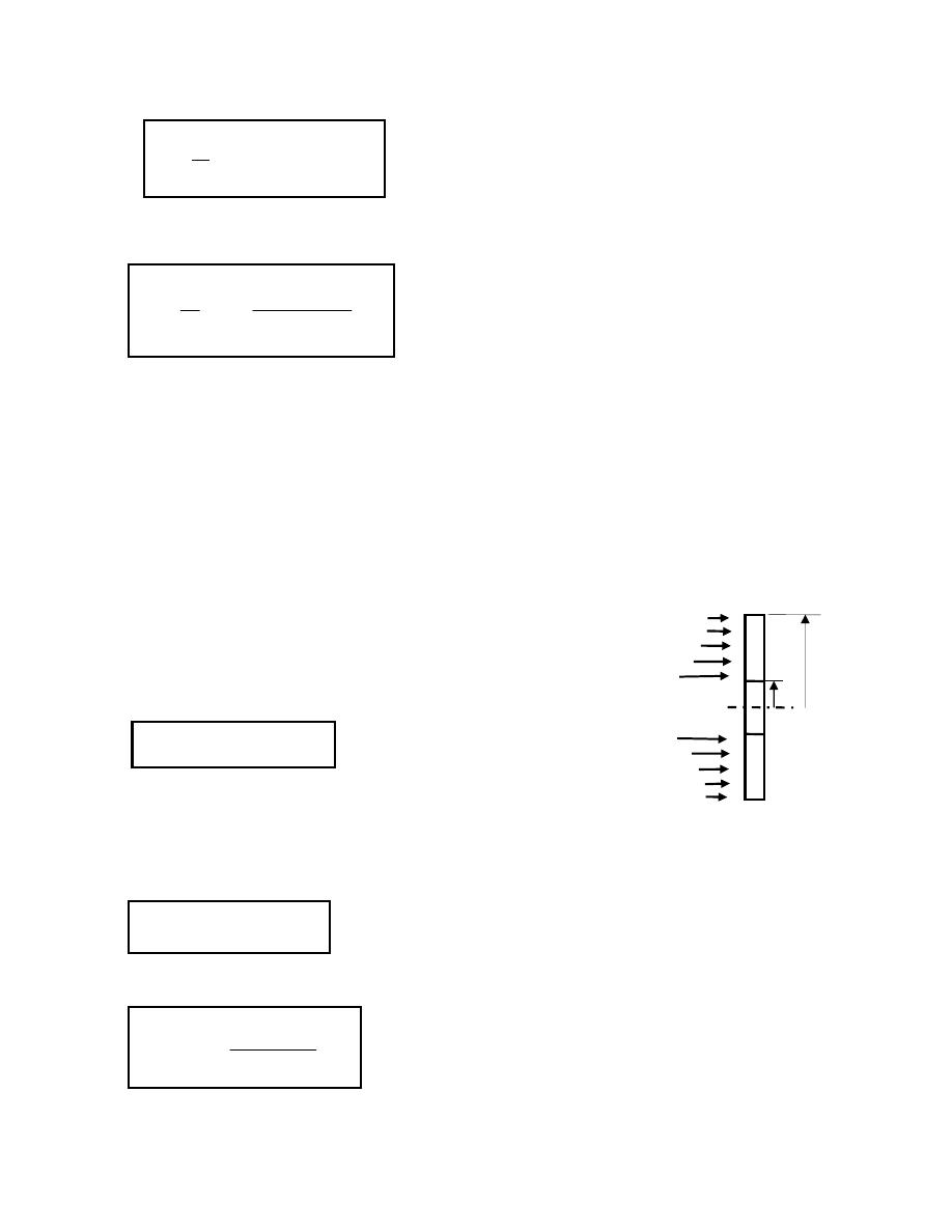
10.1.6 Worn layers
During operation of the clutch, the pair of surfaces of contact are subjected to
mechanical wear, then the thickness of the plates will decreases and the compressive
deflection in the springs of toggle mechanism will relaxed, then the change in the
thickness of plates will be equal to the relaxation in the springs.
Let
t = the change in the thickness of plates
l = layer thickness worn due to mechanical wear
If
∆W represent the change in normal force
Example 2: A plate clutch has three discs on the driving shaft and two discs on the
driven shaft. The outside and inside diameter of the contact surfaces are 240 mm and
120 mm respectively. Assuming uniform pressure and
µ
= 0.3; find the total spring
load pressing the plates together to transmit 23 kW at 1575 rpm. If there are 6 springs
each of stiffness 13 kN/m and each of contact surfaces has worn away by 1.25 mm,
find also the maximum power that can be transmitted, assuming uniform wear.
Solution:
ω = 2
π
*1575/60 = 164.9 rad/s
Torque, T = power/
ω
= 23000/164.9 = 139.45 N.m
For uniform pressure:
s = 6 springs; n = 3+2-1 = 4 pairs of contact, i.e. There are 8 layers in contact
W = k*
∆*s
t = 2*n*l
∆W = k*t*s
N
W
n
r
r
r
r
W
2
T
1245
;
*
)
(
)
(
3
2
2
2
1
3
2
3
1
=
∴
−
−
=
µ

- 7 -
t = 2*4*1.25*10
-3
= 0.01 m = 10 mm
∆W = k*t*s = 13000 * 0.01 * 6 = 780 N
∴
New axial load
W
new
= 1245 – 780 = 465 N
For uniform wear;
T = n*W
new
*R*
µ = 4*465*0.09*0.3 = 50.22 N.m
Maximum power transmitted = T *
ω = 50.22 * 164.9 = 8.283 kW
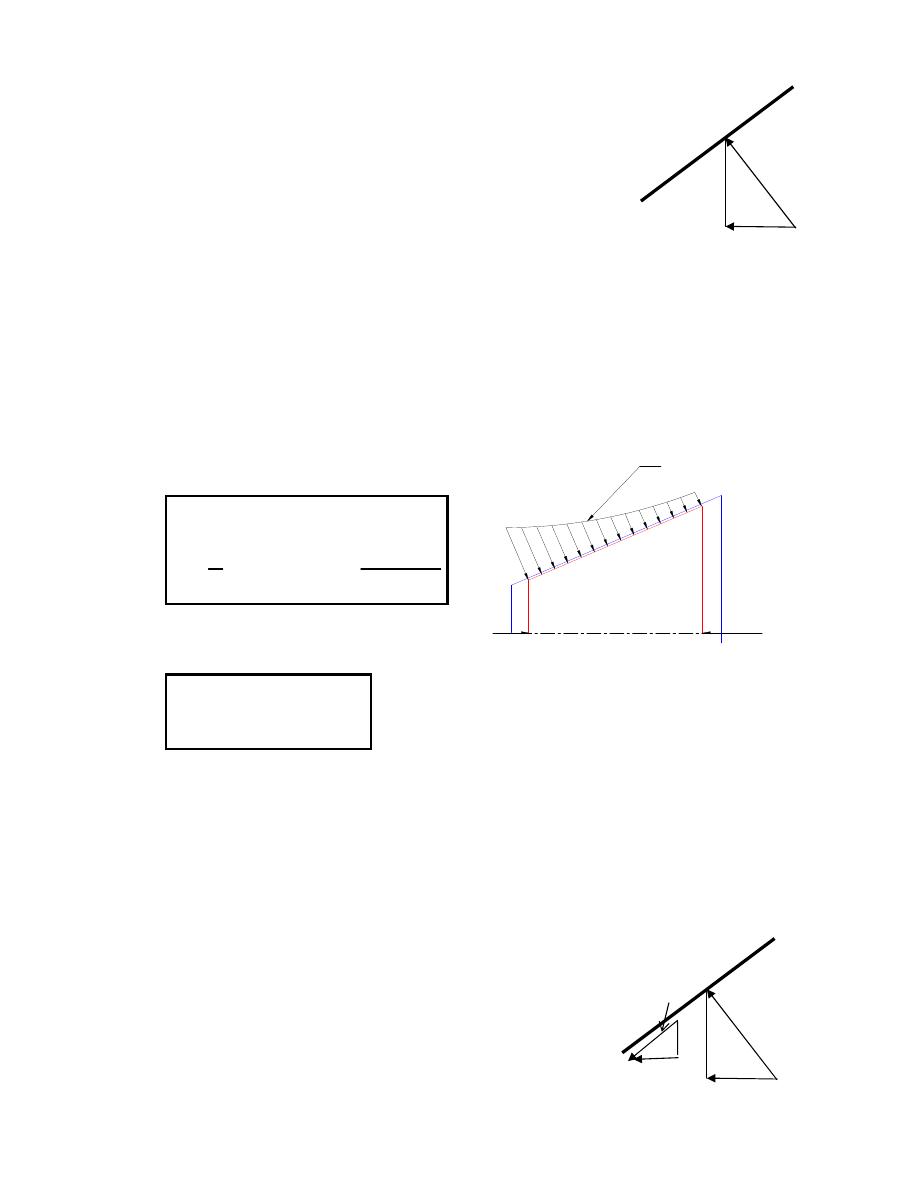
10.2 Cone Clutch
10.2.1 Geometry:
r
1
= D/2 outer radius
r
2
= d/2 inner radius
R = current radius
α
= semi-angle of cone
S = width of conical surface
R = mean radius
R = (r
1
+r
2
)/2,
S = (r
1
-r
2
)*cosec
α
10.2.2 Maximum transmitted torque:
Consider an element of width (dr*cosec
α
) along the width of cone:
N = normal force between friction surfaces
P = pressure intensity between contact surfaces
F
= friction force between contact surfaces
W = axial componenent on the normal force
W
- 8 -
T = maximum transmitted torque
dN = P*2
πrdr*cosecα
dW = dN*sin
α
∴ dW = P*2πrdr
dF =
µ*dN = µP*2πrdr*cosecα
and dT = r*dr =
µP*2πr
2
dr*cosec
α
∫
=
∴
1
2
*
cos
*
2
r
r
2
dr
Pr
ec
T
α
πµ
•
for uniform pressure theory:
•
for uniform wear theory:
where c = P
max
*r
2
10.2.3 Minimum applied axial force for no slipping (F
a
):
While applying axial forces, some of them consumed in resisting the tangential
friction surface, as shown
F =
µ*N
F
ta
=
µ*N*cosα (axial component of F)
but N = W/sin
α
∴
F
ta
=
µW*cotα
∫
=
∴
1
2
2
r
r
dr
Pr
W
π
)
(
)
(
*
cos
*
3
2
)
(
2
2
2
1
3
2
3
1
2
2
2
1
r
r
r
r
ec
W
T
r
r
P
W
−
−
=
−
=
α
µ
π
α
µ
π
ec
R
W
T
r
r
c
W
cos
*
)
(
2
2
1
=
−
=
α
N
W
Pressure distribution after wear
r
1
r
2
P
max
α
N
W
F=
µN
F
ta
=
µNcosα
α

- 9 -
Required axial force:
Example 3: A cone clutch of the following specification
R = 0.4 m;
ω
= 1300 rpm; S = 0.066 m;
α = 16°; µ = 0.28; P
max
= 72 kN/m
2
Find:
a) maximum power for no slipping;
b) minimum axial load required for maximum power to hold the clutch in
engagement.
Solution:
R = (r
1
+r
2
)/2 and S = (r
1
-r
2
)*cosec
α
∴
r
1
= 0.409 m, and r
2
= 0.3909 m
c = P
max
*r
2
= 72000*0.3909 = 28145.086 N/m
Power = T*
ω = 1300.6*(2
π
*1300/60) = 177.068 kW
Required axial force is:
10.3 Centrifugal Clutches:
A centrifugal clutch consists of a number of shoes, which can move in radial guides
and bear on the inside of an annular rim, Figure 10.5. The outer surfaces of the shoes
are covered with a frictional material, and as the speed rises, the centrifugal force on
the shoes causes them to transmit power by friction to the rim.
F
a
= W + F
ta
= W*(1+
µ*cotα)
m
N
ec
R
W
T
N
r
r
c
W
.
6
.
1300
cos
*
8
.
3200
)
(
2
2
1
=
=
=
−
=
α
µ
π
F
a
= W + F
ta
= W*(1+
µ*cotα) = 6.326 kN
- 10 -
Springs are fitted to keep the shoes clear of the rim at low speeds and thus allow the
motor to gain speed before taking up the load.
Let:
n = number of shoes
F
c
= centrifugal force on each shoe
F
s
= inward force on each shoe exerted by
spring
R = inside radius of rim
µ = coefficient of friction between rim and shoe
k = spring stiffness (constant)
m = mass of one shoe
r = radius of shoe's mass center
Net outward force (radial forces):
F
s
= k.
∆
and F
c
= m.r.
ω
2
where
Friction force on rim:
F
f
=
µ*( F
c
– F
s
) =
µ* F
n
for one shoe
Transmitted torque:
T
sh
= F
f
.R =
µ.R.( F
c
– F
s
)
for one shoe
The total friction torque is:
critical speed
ω
c
: that speed at which
The
shoes begin to move toward the rim.
At critical speed F
c
= F
s
Figure 10.5: Centrifugal clutch
Rim
Shoe
Beam
spring
Housing
F
n
= F
c
– F
s
T = n * T
sh
= n.
µ.R.( F
c
– F
s
)
F
c
= F
s
= m.r.
ω
c
2
∴ω
c
=
√(F
c
/m.r)

- 11 -
Example 4: A centrifugal clutch of the following specification;
m= 2kg, r= 0.15m, k= 50kN/m,
∆= 0.01m, µ = 0.3, ω =60rad/s, R =0.19m, and n = 3.
Solution:
F
s
= k.
∆ = 500 N
F
c
= m.r.
ω
2
= 1080 N
F
n
= F
c
– F
s
= 580
N
T = n.
µ.R. F
n
= 99.2 N.m
Power = T*
ω = 99.2 * 60 = 5.9 kW
Example 5: In a cone clutch, the contact surfaces have an effective diameter of 75
mm. The semi-angle of the cone is 15
°
.
µ
= 0.3. Find the torque required to produce
slipping of the clutch if the axial force applied is 180 N. This clutch is employed to
connect an electric motor, running uniformly at 1000 rev/min, with a flywheel, which
is initially stationary. The flywheel has a mass of 13.5 kg and its radius of gyration is
150 mm. Calculate the time required for the flywheel to attain full speed and the
energy lost in the slipping of the clutch.
Solution:
ω = 2π* 1000/60 = 104.72 rad/s
J = mass * k
2
= 13.5 * 0.15
2
= 0.30375 kg m
2
N
824
.
7
15
ec
cos
0375
.
0
*
180
*
3
.
0
ec
cos
R
*
W
T
=
=
=
o
α
µ
For the flywheel, T = J*α
∴ 7.824 = 0.30375 * α
∴α = 25.758 rad/s
2
∴ Time taken, t = ω / α = 104.72 / 25.758 = 4.065 sec
Let
θ
m
and
θ
f
be the angles turned through by the motor and flywheel respectively
before slipping ceases.
Then
θ
m
=
ω * t = 104.72 * 4.065 = 425.68 rad
- 12 -
Since the flywheel accelerates uniformly from rest to 1000 rev/min
θ
f
= ½
θ
m
= 212.84 rad
Work done by motor = T *
θ
m
Work done on flywheel = T *
θ
f
∴
Work lost in friction = T (
θ
m
-
θ
f
) = 7.824 (425.68 – 212.84) = 1665.2 J
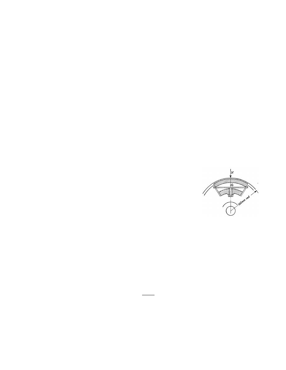
Example 6: Figure 10.6 shows one of the four shoes of a centrifugal clutch. The
contact surface is 160 mm radius and the friction force is
µ
S, where S is the resultant
of the normal forces on the surface and
µ
= 0.25. The center of gravity is 25 mm from
the contact surface. The clutch is to commence engagement at 500 rev/min. If it is to
transmit 20 kW at 750 rev/min, calculate the corresponding value of S and find the
mass of each shoe and the pressure of the beam spring on the adjusting screw. If the
spring has a stiffness of 170 kN/m, find the power transmitted at 750 rev/min when the
shoes have worn 2 mm, if not adjusted.
Solution:
Radius of c.g. of shoe, r = 160 – 25 = 135 (mm)
ω = 2π*N/60 = 0.1047*N
(rad/s)
∴
Centrifugal force on each shoe,
F
c
= mr
ω
2
= m*(2
π*N/60)
2
* 0.135
= 0.00148 m N
2
(N)
At 750 rev/min,
T = power /
ω = 20000 / (0.1047*N) = 20000 / (0.1047*750)
= 254.64
≅ 255
(N.m)
The total friction torque, T = n *
µ * S * R
255 = 4 * 0.25 * S * 0.16
∴ S = 1593.75≅ 1594 (N)
When the shoe makes contact with the rim, the spring force remains constant as the
speed rises and is therefore equal to the centrifugal force at 500 rev/min.
S = F
c
– F
s
1594 = 0.00148 m 750
2
- 0.00148 m 500
2
Figure 10.6

- 13 -
∴ m = 3.446
(kg)
Pressure on beam spring at 750 rev/min = spring force at 500 rev/min
= 0.00148 *3.446* 500
2
= 1275
(N)
When shoe wears 2 mm, increase in spring force = 170000 * 0.002
= 340 (N)
∴ new spring force = 1275 + 340 = 1615 (N)
New centrifugal force = 3.446 * ( 2
π*750/60)
2
* (0.135+ 0.002)
= 2912.16
(N)
S = 2912.16 – 1615 = 1297.16
(N)
Power = 20 * 1297.16 / 1594
= 16.27
(kW)
Example 7: Establish a formula for the maximum torque transmitted by a single plate
clutch of internal and external radii r
2
and r
1
if the limiting coefficient of friction is
µ
and the axial spring loading is W. Assuming that the pressure intensity on the contact
faces is uniform.
Apply this to determine the time required to accelerate a countershaft of rotating mass
500 kg and radius of gyration 200 mm to the full speed of 250 rev/min from rest
through a single plate clutch of internal and external radii 125 mm and 200 mm taking
µ
as 0.3 and spring load as 600 N.
Solution:
For the first part of the question see page 3 above.
ω = 2π*250/60 = 26.2 rad/s
J
shaft
= M*k
2
= 500 * 0.2
2
= 20 kg m
2
;
n
*
)
r
r
(
)
r
r
(
W
3
2
T
2
2
2
1
3
2
3
1
−
−
=
µ

- 14 -
For the given data:
T = 59.538 N m
T = J * α
∴
α = 59.538 / 20 = 2.98 rad/s
2
t =
ω / α = 26.2 / 2.98 = 8.79 sec
Example 8: A friction clutch is to transmit 10 kW at 3000 rpm. It is to be of single
plate type with both sides of the plate effective, the axial pressure being limited to be
0.09 N/mm
2
. If the external diameter of the friction lining is 1.4 times the internal
diameter, find the required dimensions of the friction lining.
Assume uniform wear conditions. The coefficient of friction may be taken as 0.3.
Solution:
Power = T *
ω
∴ T = 10000 * 60/2π*3000 = 31.83 N m
Dimensions of friction lining:
Let r
1
and r
2
external and internal radii of frictional lining
We know that for uniform wear conditions, p
max
* r
2
= c
∴ c = 0.09 * 10
6
*
r2
∴
Total load transmitted to the friction lining,
∴W = 2π * c (r
1
– r
2
) = 2
π * 0.09 * 10
6
* r
2
(1.4r
2
– r
2
) = 226194.67
2
2
r
T = n
µWR
31.83 = 2 * 0.3 * 226194.67
2
2
r
* (1.4r
2
+ r
2
)/2
∴
3
2
r
=1.954437 *10
-3
r
2
= 0.05803 m = 58.03 mm
and r
1
= 1.4 * 58.03 = 81.246 mm

- 15 -
Example 9: An engine developing 45 kW at 1000 rpm is fitted with a cone clutch
built inside the flywheel. The cone has a face angle of 12.5
°
and a maximum mean
diameter of 500 mm. The coefficient of friction is 0.2. The normal pressure on the
clutch face is not to exceed 0.1 N/mm
2
. Determine
1. the axial spring force necessary to engage the clutch, and
2. the face width required.
Solution:
ω = 2π*1000/60 = 104.72 rad/s
We know that torque developed by the clutch,
T = power /
ω = 45000 / 104.72 = 429.7 N m ≅ 430 N m
1. Axial spring force necessary to engaged by the clutch,
T =
µWR cosec12.5
∴ W = 430 / (0.2*0.25*cosec12.5) = 1861.38 N
2. Face width required,
Let b = Face width
We know that normal pressure on the clutch face,
p = W / (2
π * R * b * sin α)
∴ b = 1861.38 / (2π * 250 * 0.1 * sin 12.5)
= 54.75 mm
Example 10: A centrifugal clutch has four shoes, and transmits 15 kW at 900 rpm.
The speed at which the engagement beings is
¾
th of the running speed. The inside
radius of the pulley rim is 150 mm and the center of gravity of the shoe lies at 120 mm
from the center of the spider. The shoes are lined with rim for which the coefficient of
friction may be taken as 0.25. Determine
1. Weight of the shoes, and
2. Size of the shoes, if angle subtended by the shoes at the center of the spider is
60
°
and the pressure exerted on the shoes is 0.1 N/mm
2
.

- 16 -
The running speed;
ω = 2π*900/60 = 94.25 rad/s
The engagement speed;
ω
1
= ¾
ω = 70.7 rad/s
The torque at running speed;
T = power /
ω = 15000 / 94.25 = 159.15 N m
1. Weight of the shoes;
Let m = weight of the shoes in kg,
We know that the centrifugal force acting on each shoe
F
c
= m * r *
ω
2
= 1065.9675m
N
And the inward force on each shoe exerted by the spring i.e. the centrifugal force at
the engagement speed
ω
1
,
F
s
= m * r *
ω
1
2
= 599.82m
N
∴
Frictional force acting tangentially on each shoe,
F
f
=
µ(F
c
– F
s
)= 0.25(1065.97m – 599.82m) = 116.54m
∴
Transmitted torque:
T
sh
= F
f
* R = 116.54 * 0.15 = 17.48m
N
for one shoe
The total friction torque is:
T = n * T
sh
= 4 * 17.48m =70m
N
∴ m = 159.15 / 70 = 2.276 kg
2. Size of the shoe,
l = contact length of shoes in mm,
b = width of the shoes in mm,
θ = angle subtended by the shoes at the center of the spider in rad,
p = pressure exerted on the shoes in N/mm
2
l =
θ * R = 60° * (π/180) * 150 = 157.08 mm
p = (F
c
– F
s
)/ l*b
∴ b = (1065.9675m - 599.82m)/ .1* 157.08 = 67.5 mm

- 17 -
Example 11: A centrifugal clutch has four shoes which slide radially in a spider keyed
to driving shaft and make contact with the internal cylindrical surface of a rim keyed
to the driven shaft. When the clutch is at rest, each shoe is pulled against a stop by a
spring to leave a radial clearance 5 mm between the shoe and the rim. The pull exerted
by the spring is then 500 N. The mass center of the shoe is 160 mm from the axis of
the clutch.
If the internal diameter of the rim is 400 mm, the mass of each shoe is 8 kg, the
stiffness of each spring is 50 kN/mm and the coefficient of friction between the shoe
and the rim is 0.3; find the power transmitted by the clutch at 500 rpm.
Solution:
ω = (2π*500/60) = 52.36 rad/s
r
1
= r +
∆ = 160 + 5 = 165 mm = 0.165 m
F
c
= mr
1
ω
2
= 8 * 0.165 * (2
π*500/60)
2
= 3618.8 N
F
s
= 500 + 50 * 10
3
* 0.005 = 750 N
F
n
= F
c
– F
s
= 3618.8 – 750 = 2868.855 N
Total frictional torque, T = n *
µ * F
n
* R = 4 * 0.3 * 2868.855 * 0.2
= 688.525 N m
Power transmitted = T *
ω = 688.525 * 52.36 = 36051 Watt = 36.051 kW