3. GEAR TRAINS
3.1 Introduction:
Sometimes, two or more gears are made to mesh with each other to transmit power from
one shaft to another. Such a combination is called
of the train used depends upon the velocity ratio required and the relative position of the
axes of shafts. A gear train may consist of spur, bevel or spiral gears.
3.2 Types of gear Train:
Depending upon the arrangement of wheels,
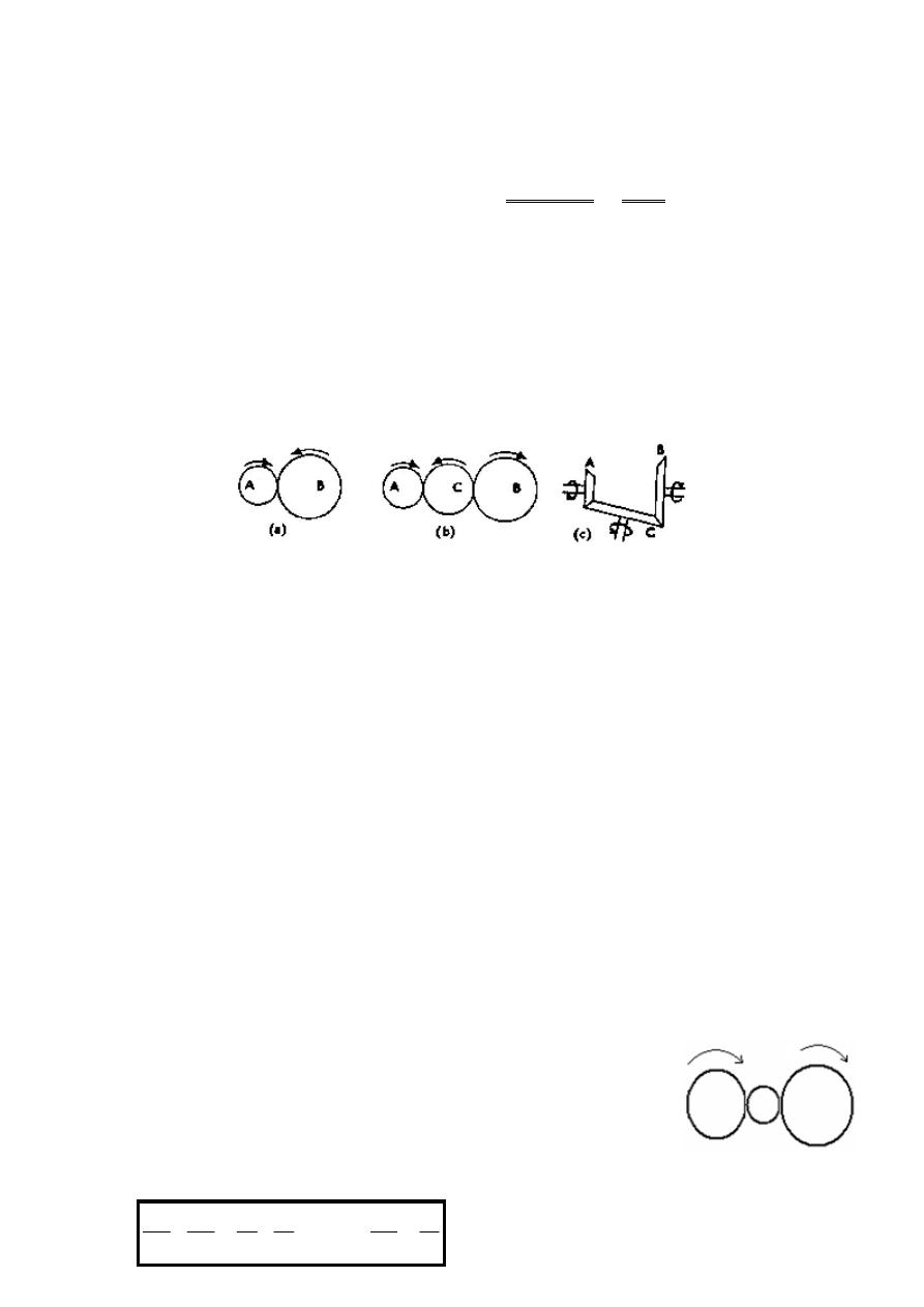
3.2.1 Simple Gear Train: A train which each shaft carries only one gear, Figure
It may be noted that when the number of intermediate wheels
follower will be in the opposite direction of the driver as shown in Figure
if the number of intermediate wheels is
follower) will be in the same direction as shown in
Now consider a simple train of wheels with one intermediate wheel
3.2:
Let: N
1
, N
2
, N
3
= speed of driver, intermediate, and follower wheel respectively in (rpm).
T
1
, T
2
, T
3
= Number of teeth on driver, intermediate, and
respectively.
Since the driver gears with the intermediate
N
2
/N
1
= T
1
/T
2
Similarly, as the intermediate wheel gears with the follower
N
3
/N
2
= T
2
/T
3
Multiplying Equation (i) and (ii),
2
1
3
2
1
2
2
3
N
N
or
T
T
x
T
T
N
N
x
N
N
=
1
Sometimes, two or more gears are made to mesh with each other to transmit power from
one shaft to another. Such a combination is called gear train or train of wheels. The nature
of the train used depends upon the velocity ratio required and the relative position of the
axes of shafts. A gear train may consist of spur, bevel or spiral gears.
Depending upon the arrangement of wheels, there are four different types of gear trains.
A train which each shaft carries only one gear, Figure
Figure 3.1
when the number of intermediate wheels is even, the motion of the
follower will be in the opposite direction of the driver as shown in Figure 12.1
number of intermediate wheels is odd, the motion of both wheels (i.e. driver and
will be in the same direction as shown in Figure 3.1b.
Now consider a simple train of wheels with one intermediate wheel, as shown in Figure
= speed of driver, intermediate, and follower wheel respectively in (rpm).
= Number of teeth on driver, intermediate, and follower wheel
Since the driver gears with the intermediate wheel,
(i)
Similarly, as the intermediate wheel gears with the follower
(ii)
3
1
1
3
T
T
N
N
=
3
2
Figure 3.2
Sometimes, two or more gears are made to mesh with each other to transmit power from
of wheels. The nature
of the train used depends upon the velocity ratio required and the relative position of the
there are four different types of gear trains.
A train which each shaft carries only one gear, Figure 3.1.
even, the motion of the
12.1a. However,
odd, the motion of both wheels (i.e. driver and
shown in Figure
= speed of driver, intermediate, and follower wheel respectively in (rpm).
follower wheel
In general, the velocity ratio (VR) in simple gear train case can be determined as below:
Similarly, it can be proved that the above equation also holds good, even if there are any
number of intermediate wheels. The velocity ratio, in a simple train of gears, is depends
only on the number of teeth on the last and first gears. The intermediate wheels (idler
gears) decide the direction of follower.
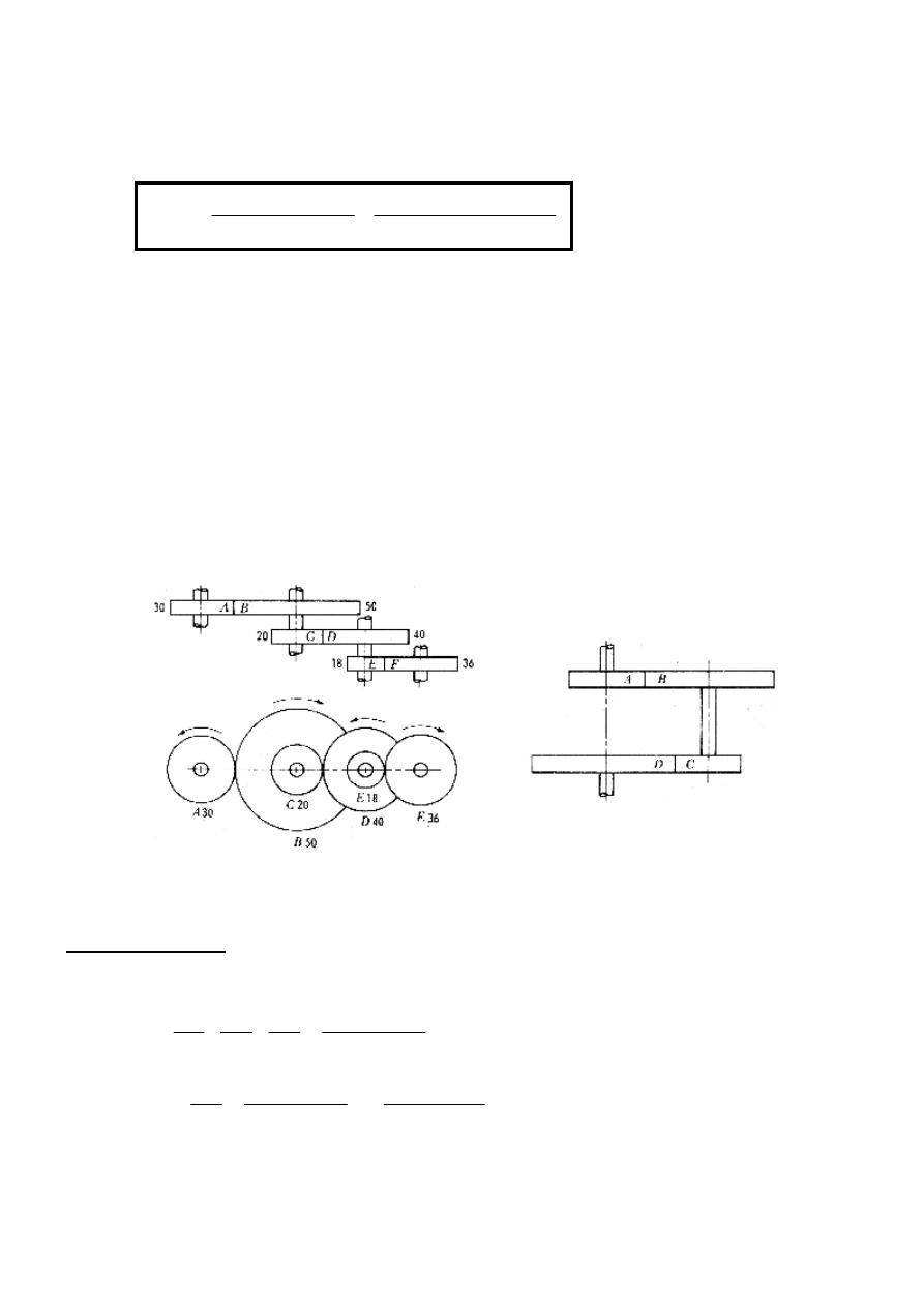
3.2.2 Compound Trains: A train in which each shaft, except the first and last, have
two gears fastened together on the same shaft to operate as an integral part, see Figure
3.3a.
Figure 3.3
Train value (TV):
The train value of the compound gear train in Figure 3.3a is:
(
)
E
D
C
B
F
D
B
E
C
A
E
F
C
D
A
B
N
N
and
N
N
T
T
T
T
T
T
N
N
x
N
N
x
N
N
TV
=
=
=
=
Q
*
*
*
*
15
.
0
36
*
40
*
50
18
*
20
*
30
*
*
*
*
−
=
−
=
=
=
∴
F
D
B
E
C
A
A
F
T
T
T
T
T
T
N
N
TV
The negative sign means that, gear F rotates in opposite direction of A.
In general,
follower
on
teeth
of
No
driver
on
teeth
of
No
driver
of
Speed
follower
of
Speed
VR
.
.
=
=
∴
(a)
(b)
Driver
Follower
3.2.3 Reverted Gear Train:
axial, the train is known as reverted gear train as shown in Figure
trains are used in automotive transmissions, lathe back
minute- and hour-hand shafts are coaxial).
(
Same
T
T
T
T
r
r
r
r
D
C
B
A
D
C
B
A
+
=
+
+
=
+
where r
A
, r
B
, r
C
, and r
D
= Radii of the respective gears.
The advantages of compound train over a simple train is that much larger speed reduction
from the first to the last can be obtained with small gears. If a simple train were used to
give a large speed reduction, last gear would have to be large. Usually foe a speed
reduction in excess of 7 to 1 a simple train is not used; instead a compound train or wor
gearing is employed.
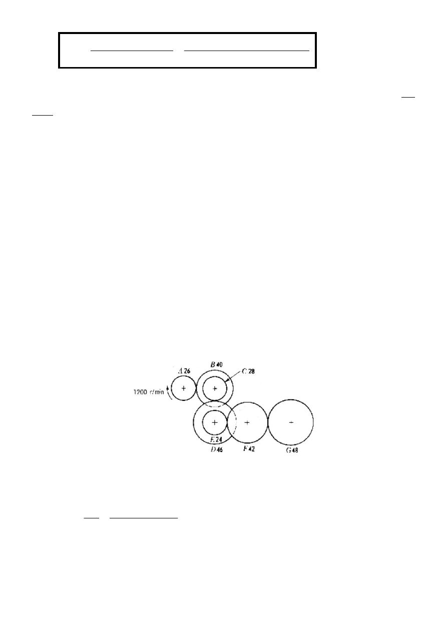
Example 3.1: Determine the revolutions per minute and direction of rotation of gear G in
the gear train shown in Figure 3.4.
Solution:
197826
.
0
*
197826
.
0
48
*
42
*
46
*
40
42
*
24
*
28
*
26
N
N
N
N
TV
A
G
A
G
=
=
∴
=
=
=
The direction of motion is cw.
gear
first
of
Speed
gear
last
of
Speed
TV
=
=
When the axes of the first and the last gears are
, the train is known as reverted gear train as shown in Figure 3.3b.
trains are used in automotive transmissions, lathe back gears, and in clocks (where the
hand shafts are coaxial).
)
pitch
circular
Same
= Radii of the respective gears.
The advantages of compound train over a simple train is that much larger speed reduction
first to the last can be obtained with small gears. If a simple train were used to
give a large speed reduction, last gear would have to be large. Usually foe a speed
a simple train is not used; instead a compound train or wor
Determine the revolutions per minute and direction of rotation of gear G in
Figure 3.4
min
/
39
.
237
1200
*
197826
197826
.
0
r
+
=
+
=
followers
on
teeth
of
oduct
Pr
drivers
on
teeth
of
oduct
Pr
When the axes of the first and the last gears are co-
b. Reverted gear
gears, and in clocks (where the
The advantages of compound train over a simple train is that much larger speed reduction
first to the last can be obtained with small gears. If a simple train were used to
give a large speed reduction, last gear would have to be large. Usually foe a speed
a simple train is not used; instead a compound train or worm
Determine the revolutions per minute and direction of rotation of gear G in
Example 3.2: Figure 3.5 shows a compound gear train where the individual velocity ratios
for the three pairs of gears are given. Find the train value (
Solution:
(VR3)
*
(VR2)
*
(VR1)
TV
=
=
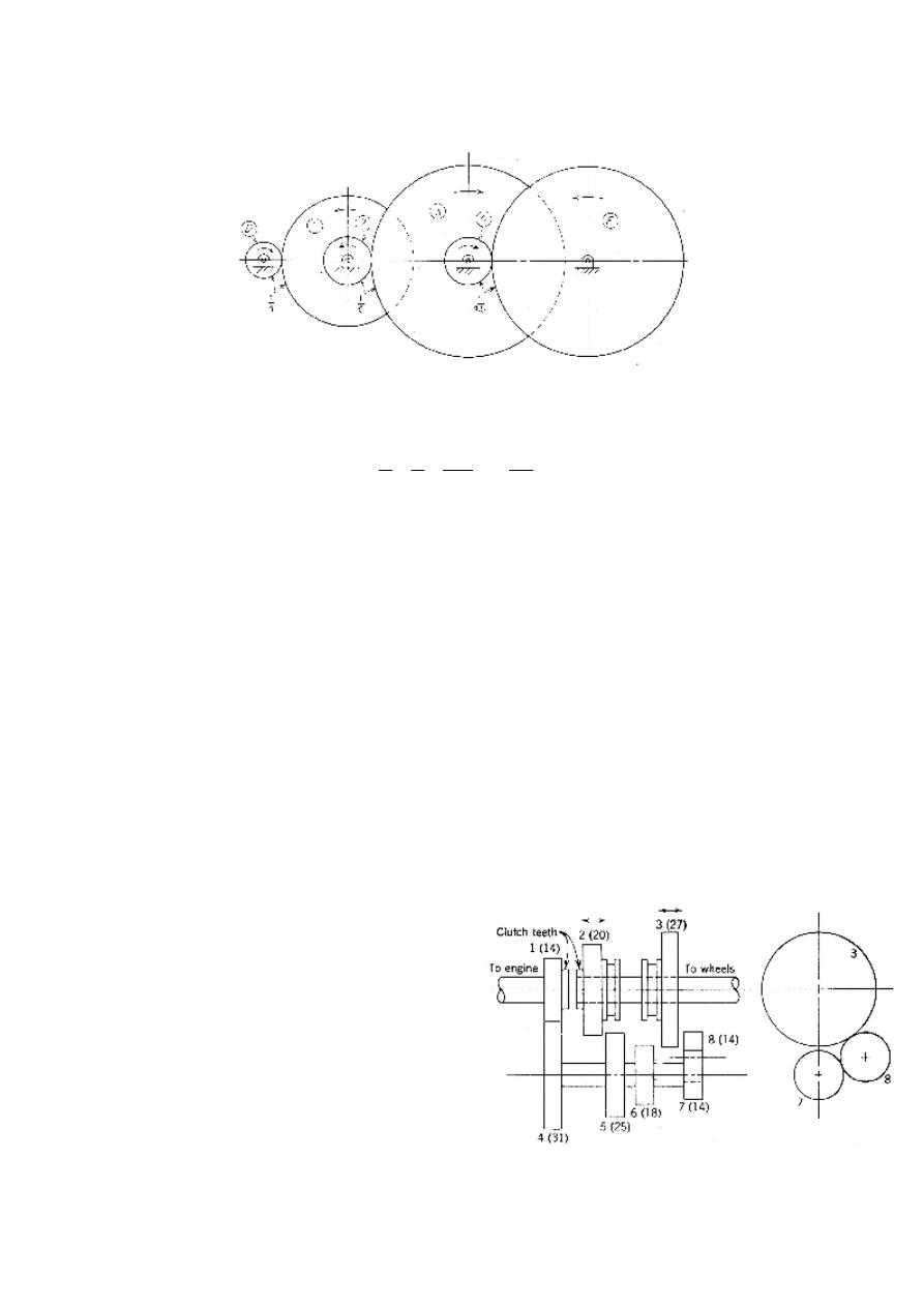
Example 3.3: A conventional automotive transmission is shown diagrammatically in
Figure 3.6. The transmission of power is as follows:
Low gear: Gear 3 shifted to mesh with gear
Second gear: Gear 2 shifted to mesh with gear
High gear: Gear 2 shifted so that clutch teeth on e
teeth on end of gear 1.
Reverse gear: Gear 3 shifted to mesh with gear
A car equipped with this transmission has a differential ratio
diameter of 686 mm. Determine the engine
conditions:
•
Low gear and car traveling 28
•
High gear and car traveling 80
•
Reverse gear and car traveling
shows a compound gear train where the individual velocity ratios
for the three pairs of gears are given. Find the train value (TV).
Figure 3.5
90
1
4.5
1
*
5
1
*
4
1
−
=
automotive transmission is shown diagrammatically in
. The transmission of power is as follows:
shifted to mesh with gear 6.
shifted to mesh with gear 5.
shifted so that clutch teeth on end of gear 2 mesh with clutch
shifted to mesh with gear 8.
A car equipped with this transmission has a differential ratio of 1:3.7 and a tire outside
mm. Determine the engine speed of the car under the following
28 km/h.
80 km/h.
Reverse gear and car traveling 8 km/h.
Figure
shows a compound gear train where the individual velocity ratios
automotive transmission is shown diagrammatically in
mesh with clutch
d a tire outside
speed of the car under the following
Figure 3.6
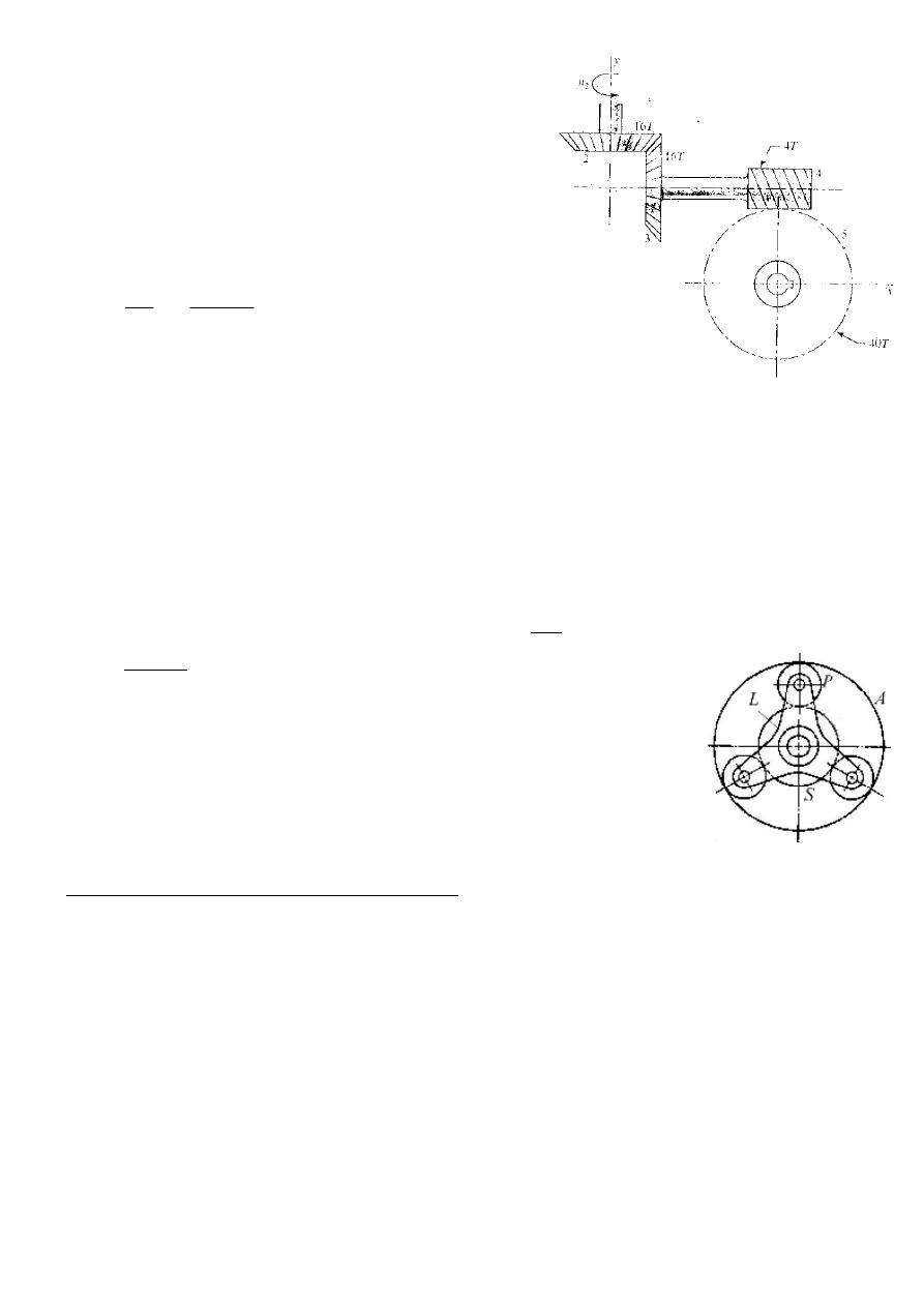
Figure 3.7
Example 3.4: Figure 3.7 shows a gear train consisting
of a pair of same size bevel gears having 16 teeth
each, a 4 tooth right-hand worm, and a 40 tooth worm
gear. The speed of gear 2 is given as N
2
= +200 r/min,
which corresponds to counterclockwise about the y-
axis. What is the speed and direction of rotation of the
worm gear?
Solution:
r/min
20
200
1
0
N
1
0
40
16
4
16
N
N
5
2
5
−
=
−
=
∴
−
=
−
=
*
.
.
*
*
Gear 5 rotates cw 20 r/min about z-axis in a right-handed coordinate.
3.2.4 Epicyclic gear Train (Planetary Gears): These are gear trains in which the
axis of one or more gears moves relative to the frame, i.e. a gear will be so driven that it
not only rotates about its own center but at the same time its center rotates about another
center.
The gear at the center, see Figure 3.8, is called the sun, and gears whose axes move are
called planets.
S is the sun-wheel.
P is a planet wheel which can rotate freely on a pin attached to the arm L.
L is the arm which rotates freely about the axis of S.
A is the annulus having internal teeth.
Two-Step Analysis of Epicyclic Gear Trains:
The following two steps are the same, no matter which member in the train is the driver
and which is the follower.
Step 1: Imagine that the entire gear train is locked together as integral part; then
rotate the entire unit one revolution clockwise.
As a result, every member in the train will rotate (+1) revolution.
Step 2: Now imagine that the gears are again free to turn, and while holding the arm
stationary, rotate the fixed gear one revolution counterclockwise (-1), back to its original
position.
Figure 3.8
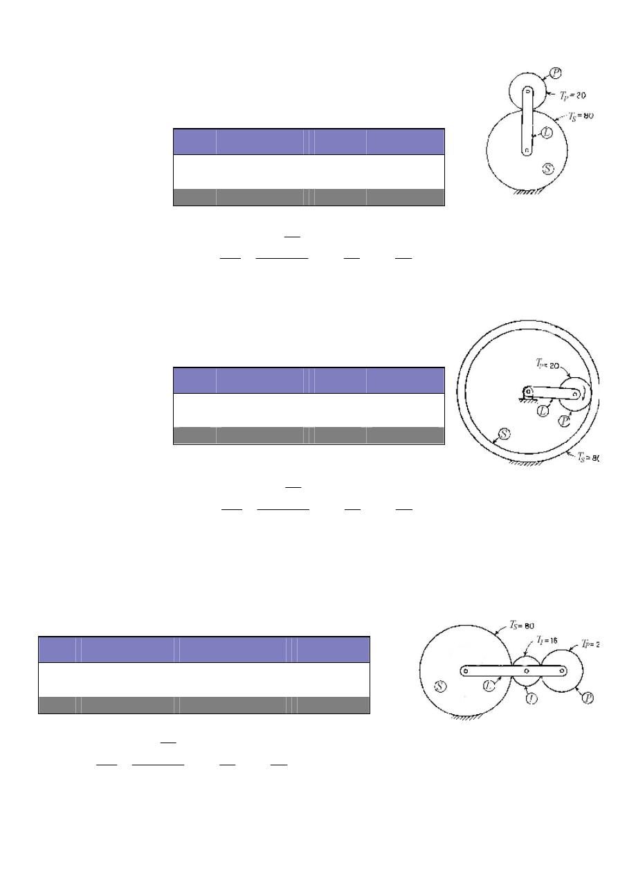
Figure 3.10
Figure 3.11
Example 3.5: Figure 3.9 shows the simplest form of Epicyclic gear train. The fixed or sun
gear has 80 teeth, and the planet gear has 20 teeth. Find the train value.
Solution:
Step Driver Arm L Fixed S Follower P
1
+1
+1
+1
2
0
-1
+T
S
/T
P
Total
+1
0
1+ T
S
/T
P
Example 3.6: Figure 3.10 shows an epicyclic gear train utilizing an
annular gear as a sun gear. The sun gear has 80 teeth, and the
follower gear has 20 teeth. Find the train value.
Solution:
Example 3.7: Figure 3.11 shows an Epicyclic gear train utilizing an idler gear. The sun
gear has 80 teeth, the idler I has 16 teeth, and the follower P has 20 teeth. Find the train
value.
Solution:
Step Driver Arm L Fixed S Follower P
1
+1
+1
+1
2
0
-1
-T
S
/T
P
Total
+1
0
1- T
S
/T
P
Step Driver Arm L Fixed S Idler I
Follower P
1
+1
+1
+1
+1
2
0
-1
+T
S
/T
I
-T
S
/T
P
Total
+1
0
1+ T
S
/T
I
1-T
S
/T
P
Figure 3.9
5
20
80
1
T
T
1
1
T
T
1
N
N
TV
P
S
P
S
L
P
+
=
+
=
+
=
+
=
=
∴
3
20
80
1
T
T
1
1
T
T
1
N
N
TV
P
S
P
S
L
P
−
=
−
=
−
=
−
=
=
∴
3
20
80
1
T
T
1
1
T
T
1
N
N
TV
P
S
P
S
L
P
−
=
−
=
−
=
−
=
=
∴
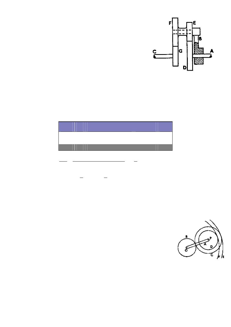
Figure 3.12
Figure 3.13
Example 3.8: Figure 3.12 shows an Epicyclic gear train in
which the wheel D is held stationary by the shaft A and the
arm B is rotated at 200 r/min. The wheels E and F are fixed
together and rotate freely on the pin carried by the arm. The
wheel G is rigidly attached to the shaft C.
Find the speed of the shaft C, stating the direction of
rotation relative to that of B.
The numbers of teeth are as follows: E 20, F 40, and G 30.
Solution:
r
d
+ r
e
= r
g
+ r
f
∴
T
d
+ T
e
= T
g
+T
f
, assuming pitches are equal
T
d
+ 20 = 30 +40
∴
T
d
= 50 teeth
∴
Speed of C = - 466.7 r/min (in opposite direction to B)
Example 3.9: In the epicyclic gear train shown in Figure 3.13 the pinion B and the internal
wheels E and F are mounted independently on the spindle, O, while C
and D form a compound wheel, which rotates on the pin P attached to
the arm A. The wheels B, C and D have 15, 30, and 25 teeth, all of the
same pitch.
a. If wheel E is fixed, what is the ratio of the speed of F to that
of B?
b. If wheel B is fixed, what are the ratios of the speeds of E and
F to that of A?
Solution:
T
E
= T
B
+ 2T
C
= 15 + 60 = 75 teeth
T
F
= T
B
+ T
C
+ T
D
= 15 + 30 + 25 = 70 teeth
a. If wheel E is fixed,
Step
B
C, G
F, E
A, D
1
+1
+1
+1
+1
2
0
- (T
D
/ T
E
)*(T
F
/ T
G
) +T
D
/ T
E
-1
Total +1 1-(T
D
/ T
E
)*(T
F
/ T
G
) 1+ T
D
/T
E
0
min
r
7
466
200
3
7
N
3
7
N
3
7
1
)
T
/
(T
*
)
T
/
(T
-
1
N
N
B
G
G
F
E
D
B
G
/
.
*
*
−
=
−
=
−
=
∴
−
=
=
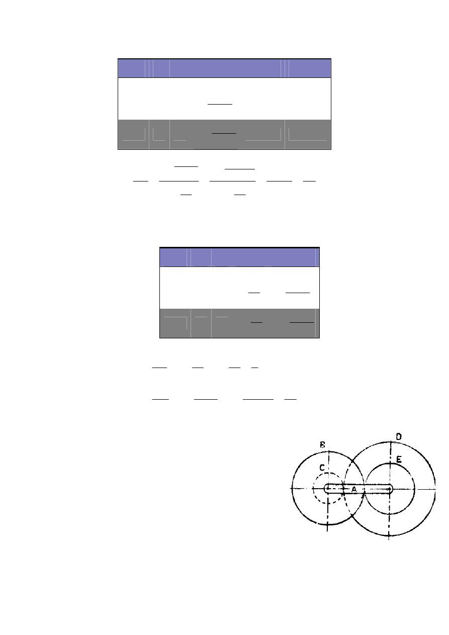
Figure 3.14
b. If wheel B is fixed,
Example 3.10: In a reverted epicyclic train, the arm A
carries two wheels B and C and a compound wheel D and
E as shown in Figure 3.14. The number of teeth on wheels
B, C and D are 75, 30, and 90 respectively. Find the speed
and direction of wheel C when wheel B is fixed and the
arm A makes +100 r/min.
Solution:
T
B
+ T
E
= T
C
+ T
D
∴
T
E
= 30 + 90 – 75 = 45 teeth
Step
A
E
F
D,C
B
1
+1 +1
+1
+1
+1
2
0
-1
F
C
D
E
T
T
T
T
.
.
−
-T
E
/T
C
+T
E
/T
B
Total +1 0 1
F
C
D
E
T
T
T
T
.
.
−
1- T
E
/T
C
1+ T
E
/T
B
Step
A
B
E
F
1
+1 +1
+1
+1
2
0
-1
E
B
T
T
+
F
C
D
B
T
T
T
T
.
.
+
Total +1 0 1
E
B
T
T
+
1
F
C
D
B
T
T
T
T
.
.
+
56
1
6
107
0
15
75
1
70
30
25
75
1
T
T
1
T
T
T
T
1
N
N
B
E
F
C
D
E
B
F
=
=
+
−
=
+
−
=
.
*
*
.
.
28
33
70
30
25
15
1
T
T
T
T
1
NA
NF
5
6
75
15
1
T
T
1
N
N
F
C
D
B
E
B
A
E
=
+
=
+
=
=
+
=
+
=
*
*
.
.
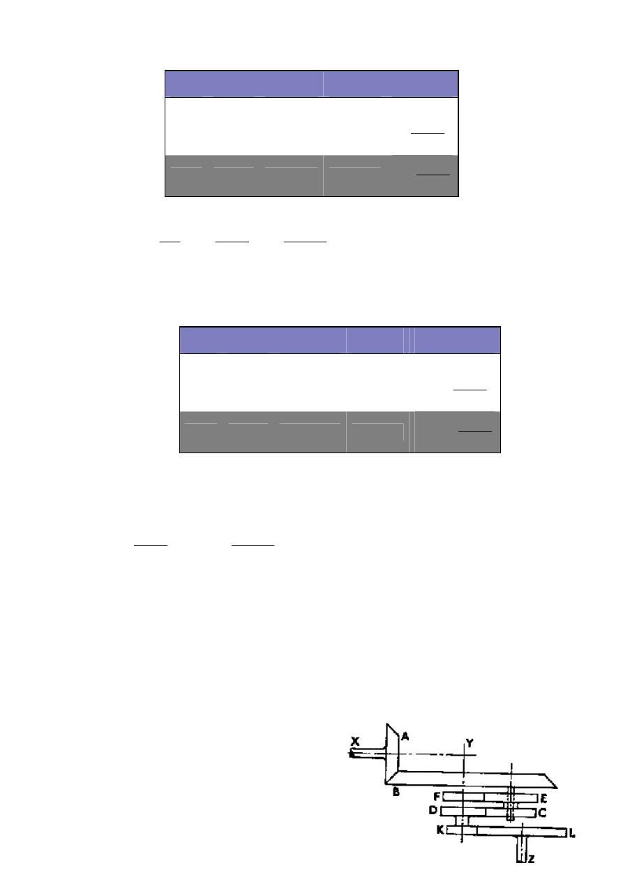
Figure 3.15
Step Arm A
D, E
Wheel B Wheel C
1
+1
+1
+1
+1
2
0
+T
B
/T
E
-1
E
C
D
B
T
T
T
T
.
.
−
Total
+1
1+ T
B
/T
E
0
1
E
C
D
B
T
T
T
T
.
.
−
min
/
*
*
*
*
.
.
r
400
100
4
N
4
N
4
45
30
90
75
1
T
T
T
T
1
N
N
A
C
E
C
D
B
A
C
−
=
−
=
−
=
∴
−
=
−
=
−
=
Alternative solution,
Since the arm A makes 100 r/min,
∴
x = 100 r/min
In addition, the wheel B is fixed,
∴
x + y = 0
and y = -x = -100
r/min
400
45
30
90
75
1
100
T
T
T
T
y
x
N
E
C
D
B
C
−
=
−
=
+
=
∴
*
*
.
.
*
Example 3.11: In the train of gear wheels shown in Figure 3.15, the shaft X runs at (-2400
r/min) and drives the bevel wheel B by the pinion A. The compound wheel EC revolves
freely on a spindle rigidly attached to B. Wheel C gears with D, and E with F, both wheels
D and F being concentric with wheel B. Wheel F is held stationary and wheel K, solid
with D, drives L on shaft Z. There are three sets of the wheels CE carried on spindles
equally spaced on B. The tooth numbers are: A 18, B 60, C = D = 22, E 23, F 21, K 19, L
64. Find the speed of shaft Z.
Solution:
Wheels A and L are not part of the epicyclic train
and must therefore be treated separately.
Step Arm A
D, E
Wheel B
Wheel C
1
+x
+x
+x
+x
2
0
-y*T
B
/T
E
+y
E
C
D
B
T
T
T
T
y
.
.
*
+
Total
+x
x-y* T
B
/T
E
x+ y
x
E
C
D
B
T
T
T
T
y
.
.
*
+
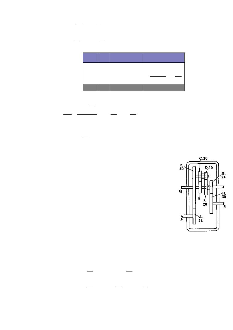
Figure 3.16
K
K
L
K
L
A
B
A
B
N
64
19
N
T
T
-
N
Also,
r/min
720
2400
60
18
N
T
T
N
*
.
)
(
*
.
−
=
=
=
−
=
−
=
Example 3.12: In the gear drive shown in Figure 3.16, the casing is
fixed. Gear wheel B rotates freely on shaft Q and carries a pin on which
rotates the wheels C and D, which are fixed together. The pitch of the
teeth is the same for all wheels. Wheel E is fixed on shaft Q. If shaft P
rotates at 200 r/min, find the speed and direction of rotation of shaft Q
for the two cases: (a) shaft R is fixed, (b) shaft R rotates at 100 r/min in
the same direction as P.
Solution:
T
E
= 28 +16 – 20 = 24 teeth
The wheels A and H are not part of the epicyclic train and must therefore be
treated separately.
Wheel B is the arm of the epicyclic train.
Step
B
C, E
F
D, K
1
+1
+1
+1
+1
2
0
+T
F
/T
E
-1
E
F
D
E
C
F
T
T
T
T
T
T
−
=
−
*
*
Total +1 1+T
F
/T
E
0
1 - T
F
/T
E
r/min
6
62
720
0869
0
N
0869
0
N
0869
0
23
21
1
T
T
1
1
T
T
1
N
N
B
K
E
F
E
F
B
K
.
*
.
*
.
.
=
=
=
∴
=
−
=
−
=
−
=
B)
to
direction
in
(opposite
r/min
58
19
6
62
64
19
N
L
.
.
*
−
=
−
=
∴
H
H
H
G
H
G
A
B
A
B
N
4
5
N
24
30
N
T
T
N
r/min
80
80
32
200
N
T
T
N
*
*
*
*
*
−
=
−
=
−
=
−
=
−
=
−
=

(a) When R is fixed, a = -80
and
a + b = 0
∴b = -a = 80
∴
N
Q
= a + b*
E
D
C
F
T
T
T
T
.
.
= -80 + 80*
24
16
20
28
*
*
= + 36.7 r/min (in
same direction to P)
(b) When R rotates at 100 r/min,
∴
N
G
=
H
N
4
5
*
−
=
125
100
4
5
−
=
−
*
r/min
a = -80
and
a + b = -125
∴b = - 45
N
Q
= -80 - 45*
24
35
= - 145.6 r/min (in opposite direction to P)
Step
B
C, D
E, Q
F, G
1
+a
+a
+a
+a
2
0
-b*T
F
/T
D
+b*
E
D
C
F
T
T
T
T
.
.
+b
Total +a a- b*T
F
/T
D
a + b*
E
D
C
F
T
T
T
T
.
.
a+ b
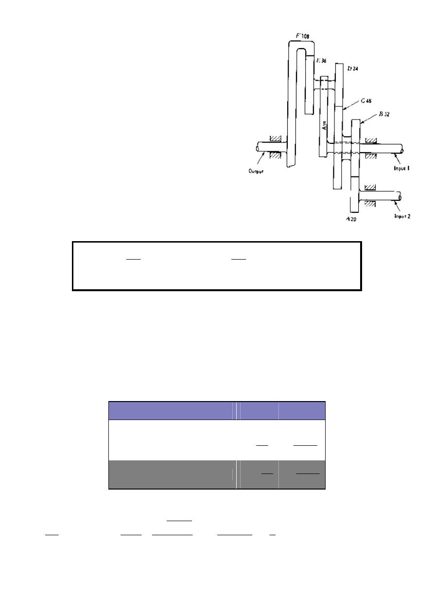
Figure 3.17
3.2.5 Epicyclics with Two Inputs:
A gear train of this type is shown in Figure 3.17.
Let N
1
, N
2
, and N
o
represent the turns of input 1,
input 2, and the output, respectively. By
superposition, the number of turns of the output
turns due to input 1 plus the output turns due to
input 2. This can be expressed in equation form as
follows:
Example 3.13: In Figure 3.17, suppose input 1 turns at 120 r/min ccw, input 2 turns at 360
r/min cw, and the speed and direction of rotation of the output shaft to be determined.
Solution:
In order to evaluate item I in Equation (*), we construct the following table. With input 2
held fixed, B and C are fixed.
Step Driver Arm Fixed C
D, E
F
1
+1
+1
+1
+1
2
0
-1
+
D
C
T
T
+
F
D
E
C
T
T
T
T
.
.
Total
+1
0
1 +
D
C
T
T
1+
F
D
E
C
T
T
T
T
.
.
3
5
108
24
36
48
1
1
.T
T
.T
T
+
1
N
N
N
N
F
D
E
C
Arm
F
fixed
held
2
Input
1
o
+
=
+
=
=
=
∴
*
*
(*)
*
*
4
4 3
4
4 2
1
4
4 3
4
4 2
1
II
fixed
held
1
Input
2
o
2
I
fixed
held
2
Input
1
o
1
o
N
N
N
N
N
N
N
+
=

Next, when evaluating item II, we do not construct a table, because with input 1 held
fixed, the rest of the system behaves as an ordinary compound gear train. Hence
Note that the sign is positive because gears F and A turn in the same directions.
Thus the speed of the output shaft is 50 r/min ccw.
12
5
108
24
32
36
48
20
followers
on
teeth
of
oduct
Pr
drivers
on
teeth
of
oduct
Pr
N
N
N
N
A
F
fixed
held
1
Input
2
o
+
=
=
=
=
*
*
*
*
(
)
r/min
50
12
5
360
3
5
120
N
N
N
N
N
N
N
2
o
2
1
o
1
o
+
=
−
+
+
=
+
=
*
*
*
*
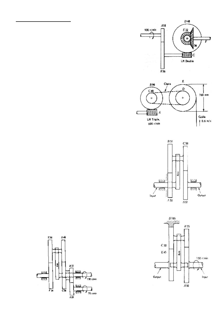
Figure P3.1
Figure P3.2
Figure P3.3
Figure P3.4
Figure P3.5
Problems (Gear Trains):
Q1) Determine the revolutions per minutes
of gear F in Figure P3.1. What is its
direction of rotation when viewed from the
right end?
( Ans: 12.857 rpm, cw when viewed
from the right end)
Q2) Determine the number of teeth on
sprocket D in Figure P3.2 if the cable
speed is to be 0.6 m/s approximately. What
is the direction of rotation of A when
viewed from the right end.
( Ans: ccw)
Q3) Determine the speed reduction
between the input and the output shafts in
Figure P3.3. If the input shaft rotates
clockwise when viewed from the right end,
what is the direction of rotation of the
output shaft?
( Ans: cw when viewed from the
right)
Q4) Determine the speed of rotation of the
output shaft in Figure P3.4 and its direction
of rotation when viewed from the right.
(Ans: 122.727 rpm cw)
Q5) Determine the speed and direction of
rotation of the output shaft F in Figure
P3.5.
(Ans: 82.63 rpm ccw)
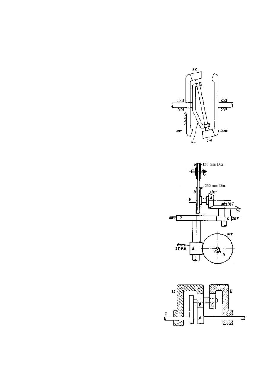
Figure P3.6
Figure P3.7
Figure P3.8
Q6) In the gear train in Figure P3.6, gear A
is fixed, the arm is the driver, and gear D is
the driven member.
a. Determine the speed reduction
for the gear train. If the arm
rotates ccw when viewed from
the right end, what is the
direction of rotation of gear D?
b. Same as (a) except the numbers
of teeth on gear A and D are
interchanged.
(Ans:-1/300, +1/301)
Q7) Figure P3.7 shows a gear train
consisting of bevel gears, spur gears, and a
worm and worm gear. The bevel pinion is
mounted on a shaft which is driven by V
belt on pulleys. If pulley 2 rotates 1200
r/min in the direction shown, find the
speed and direction of rotation of gear 9.
(Ans: 11.84 rpm cw)
Q8) If, in the epicyclic gear train shown in
Figure P3.8, gear A rotates at 1000 r/min
cw, while E rotates at 500 r/min ccw,
determine the speed and direction of
rotation of the annulus D, and of the shaft
F. All gears are of the same pitch, and the
number of teeth in A is 30, in B is 20 and
in E is 80.
(Ans: 371.4 rpm ccw, 40 rpm cw)
Q9) In the epicyclic shown in Figure P3.9,
the gear B has 120 teeth externally and 100
internally. The driver A has 20 teeth and
the arm E is connected to the driven shaft.
Gear D has 60 teeth. If gear A revolves at
+ 100 r/min and D revolves at + 27 r/min,
find the speed of the arm E.
( Ans: -0.2916 rpm)
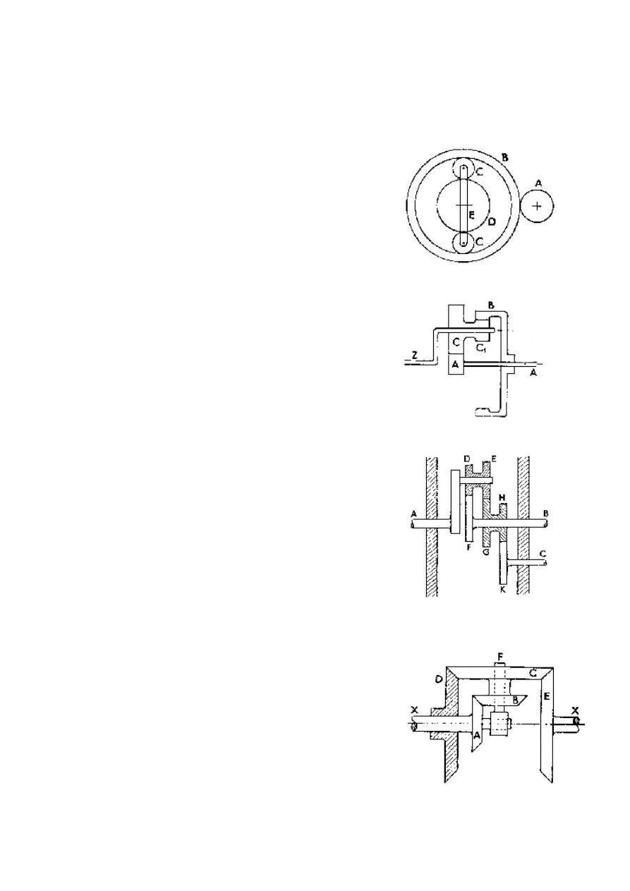
Figure P3.9
Figure P3.10
Figure P3.11
Figure P3.12
Q10) In epicyclic speed reducing gear
shown in Figure P3.10 the input shaft A
runs at 12000 r/min and the annular wheel
B is fixed. Find the speed of the output
shaft Z and the speed of the planet wheels
relative to the spindle on which they are
mounted. The numbers of teeth in the
wheels are: A = 15, C = 41, C
1
= 25, B =
81.
(Ans: 1217.53 rpm, -3945 rpm)
Q11) In the epicyclic train shown in Figure
P3.11, shaft A rotates at 1000 r/min in a
cw direction while shaft B is driven at 500
r/min in a ccw. Determine the speed and
direction of rotation of the shaft C.
All teeth are of the same module and the
numbers of teeth in the various gears are as
follows: D = 16, E = 24, F = 43, H = 35, K
= 30.
(Ans: 2058 rpm cw)
Q12) An epicyclic gear consists of bevel
wheels arranged as shown in Figure P3.12.
The driving pinion A has 20 teeth and
meshes with the wheel B that has 25 teeth.
The wheels B and C are fixed together and
turn freely on the shaft F. The shaft F can
rotate radially about the main axis XX.
The wheel C has 50 teeth and meshes with
wheels D and E, each of which has 60
teeth. Find the speed and direction of E
when A rotates at +200 r/min, (a) if D is
fixed, (b) if D rotates at 100 r/min in the
same direction as A.
(Ans: (a) -800 rpm, (b) -
300 rpm)
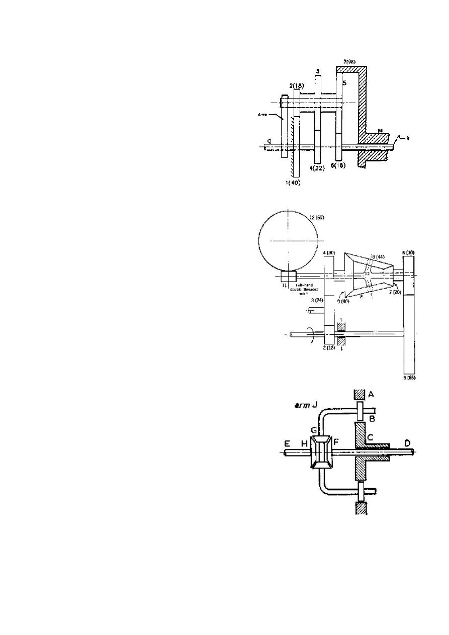
Figure P3.13
Figure P3.14
Figure P3.15
Q13) In Figure P3.13, the shaft Q is keyed
to gear 4 and turns +1000 r/min. What are
the angular velocities of the shafts R and
M, keyed, respectively, to gears 6 and 7?
The tooth numbers are in parentheses. Find
also the speed of gear 3 relative to arm. All
gears are of the same pitch.
( Ans: 1493.8
rpm, -723.35 rpm, 3.222)
Q14) In the mechanism in Figure P3.14,
gear 2 rotates at 50 r/min in the direction
shown. Determine the speed and direction
of rotation of gear 12.
Q15) The same epicyclic bevel gear train
is shown in Figure P3.6. The numbers of
teeth are A = 75, B = 20, C = 18, and D =
70. Find the speed of the driven shaft if:
1) the driving shaft makes 1000 r/min,
2) the wheel A turns in the same sense
as driving shaft at 400 r/min, the
driving shaft still making 1000
r/min.
(Ans: 36 rpm, 421.4 rpm)
Q16) Figure P3.15 shows an epicyclic gear
in which the internally-toothed annulus A
is fixed. Wheels B and G are free to rotate
on the arm J. Wheels F and H are keyed to
shafts D and E respectively. The numbers
of teeth in the gear wheels are as follows:
A = 120
C = 60
H = 50
B = 30
F = 50
G = 30
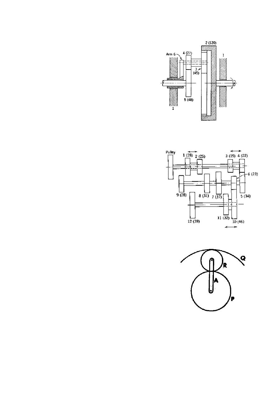
Figure P3.16
Figure P3.17
Figure P3.18
If D is driven at 80 r/min and C is driven at
50 r/min in the same direction, find the
speed and direction of rotation of the arm J
and of the shaft E.
(Ans: +50/3 rpm, -140/3
rpm)
Q17) In the planetary gear train shown in
Figure P3.16, gear 2 turns at 500 r/min in
the direction indicated. Determine the
speed and direction of rotation of arm 6 if
gear 5 rotates at 300 r/min in the same
direction as gear 2.
Q18) Figure P3.17 shows part of a gear
train for a vertical milling machine. Power
input is through the pulley and power
output through gear 12. Compound gears 1
and 2, 3 and 4, and 10 and 11 can slide as
shown to give various combinations of
gearing. Determine all of the train values
possible between the pulley and gear 12.
Q19) Figure P3.18 shows an epicyclic gear
in which the wheel P, having 45 teeth 0f 15
mm pitch, is geared with Q through the
intermediate wheel R at the end of the arm
A. When P is rotating at 63 r/min in a
clockwise direction, and A is rotating at 9
r/min, also in a clockwise direction, the
wheel Q is required to rotate at 21 r/min in
an anticlockwise direction.
Find the necessary numbers of teeth in Q
and R, and the P.C.D. of Q.
(Ans: 81, 18, 386.75 mm)