CHAPTER 2
Gears
2.1 Introduction:
Toothed gears are used in machines to transmit
♦
Rotary motion (various speed, multi-outputs in different directions)
♦
Torques or power (gears resist higher against torque)
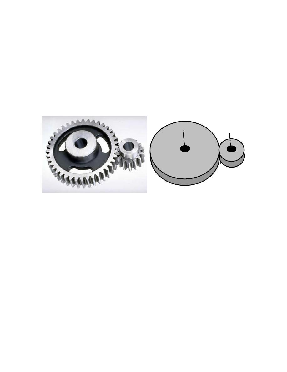
Teeth need to be specially shaped to allow smooth engagement, Figure 1.
Figure 1: Spur gears.
2.2 Types of Gears:
It is conventional to classify gears as follows, Figure 2:
a. Spur gears: This is the simplest form of gear for transmitting motion between two
parallel shafts.
b. Helical gears: These gears are similar to spur gears except that the teeth are helical
rather than straight. The disadvantage is that an undesirable side thrust is introduced.
Herringbone gears have the smooth action of helical gears without their undesirable side
thrust, but they are expensive to produce.
c. Bevel gears: These gears are conical rather than cylindrical in form. Their main function
is to transmit motion around corners. They are in several forms (straight, spiral, skew,).
d. Worm gears:
n Large speed reduction in a relatively small space
n Have a self-looking
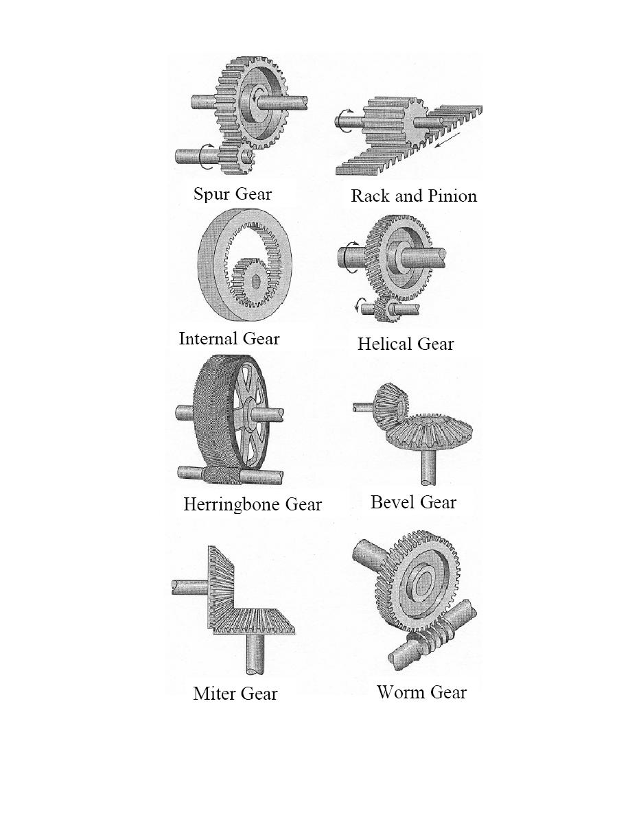
Figure 2: Gear types.
(a)
2.3 Spur Gear
2.3.1 Wheel (Gear) and Pinion
when two gears are in mesh (mating), then the larger one called the wheel or gear, and the
smaller are called the pinion. Capital and small letters respectively denote the quantities related
to gear and pinion. The pinion generally is the driver.
•
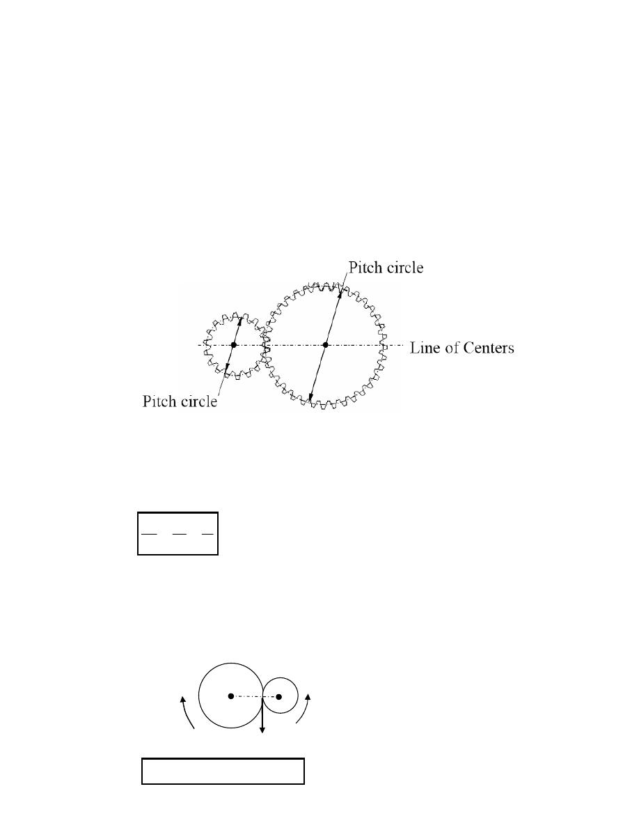
Pitch Circle or Diameter (D, d): It is an imaginary circle which by pure rolling action,
would give the same motion as the actual gear. The pitch diameter is the diameter of the
pitch circle (p.c), Figure 3. The size of the gear is usually specified by the p.c diameter.
Figure 3: Pitch circle diameter
•
Number of Teeth (T, t): Must be an integer value
Let T and t are the number of teeth of gear and pinion respectively.
where
Ω
and
ω
are the angular speed of the gear and pinion respectively. The pitch circle radii
are denoted by R and r for the gear and pinion respectively.
•
Pitch point: If two gears are in mesh, then there is a point which is located on the line
joining the centers, and has the same velocity relative to each center.
T
t
D
d
=
=
ω
Ω
D
d
Vp
Pinion
Gear
O
1
O
2
P
Ω
ω
Vp =
Ω
*(O
2
P) =
ω
*(O
1
P)
•
Circular Pitch p: It is the distance between a point on one tooth and the corresponding
point on an adjacent tooth, measured along p.c
•
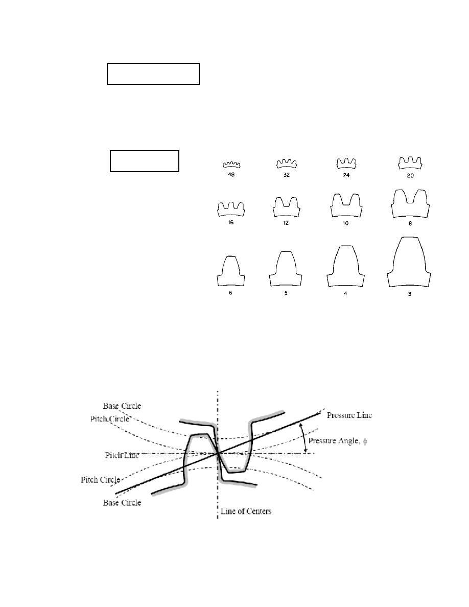
Diametral Pitch (P
d
): or simply pitch, of a gear is an expression of tooth size. It is the
number of teeth per (mm) or inch of pitch diameter. Therefore the larger numerical value
of P
d
, the smaller the teeth, Figure 4.
•
Pressure Angle (
φ)
:
It is the angle
between the common normal to
two gear teeth at the point of
contact and the common tangent
at the pitch point, Figure 5. The
common
normal
called
the
pressure line which is always pass
through pitch point.
p =
π*D/T = π*d/t
P
d
= T/D = t/d
Figure 4: Standard gear-teeth size (diametral pitch).
Figure 5: Pressure angle.
(Common tangent)
(Common normal)
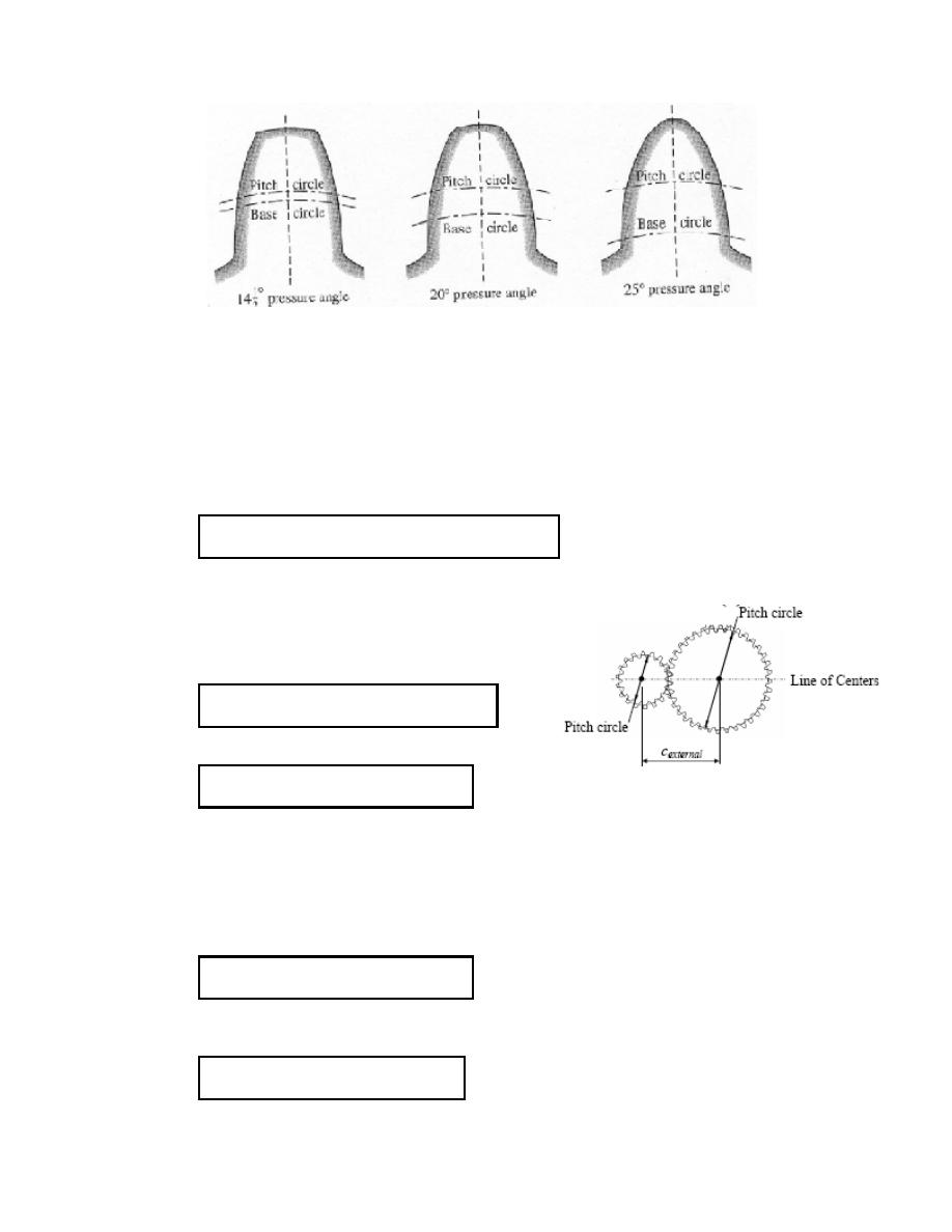
The Standard values of the pressure angles are, Figure 6:
φ = 14½°, 20°, 25°
Figure 6: Standard values of the pressure angles
Mating gears must have same pressure angle and diametral pitch.
•
Module m: The module is the index of tooth size in SI and it is the reciprocal of the
diametral pitch, that is
The mating gears must have the same module m.
•
Distance between gear centers:
m = 2R/T = 2R/t ;
∴
R = m*T/2; and r = m*t/2
For external mating:
For internal mating:
Example 1:
Two mating external 4-pitch, spur gears have 14 and 42 teeth. Determine the center distance.
•
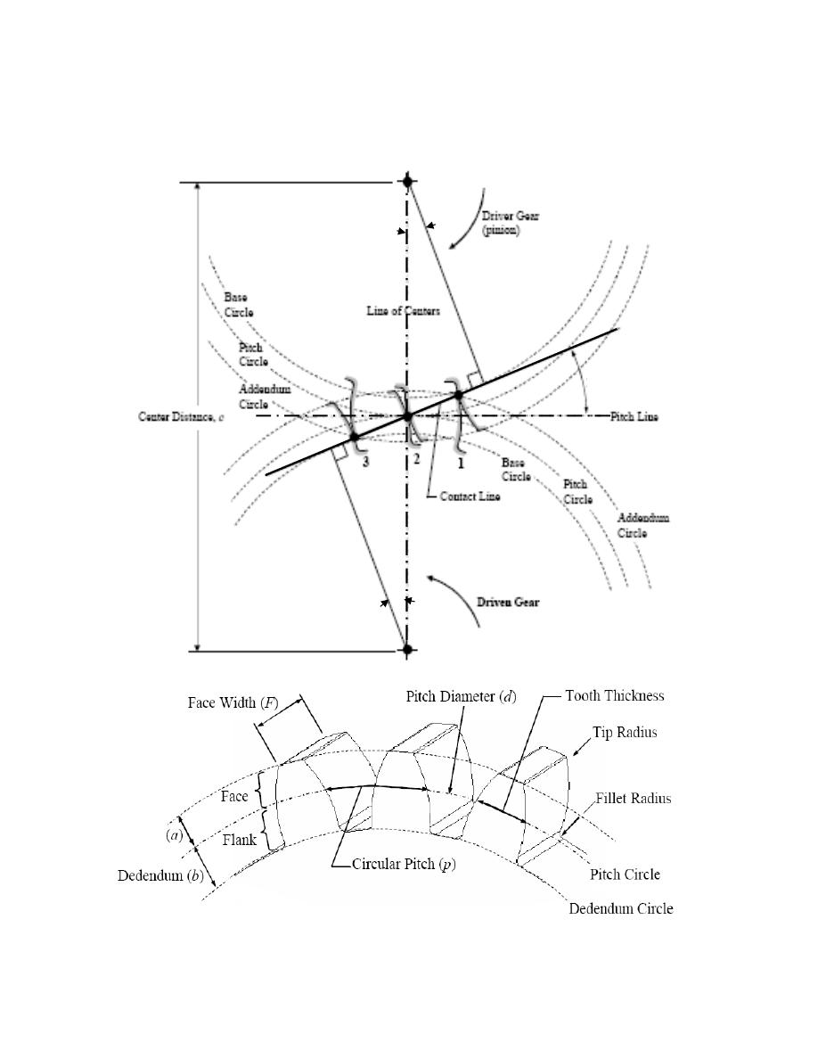
Base circle: The involute curves forming the tooth profiles are drawing from the
base circle. It is always tangent to the pressure line, Figure 7.
•
Addendum circles: They are the outer circles of radius R
a
and r
a
, Figure 7.
•
Dedendum circles: They are the root circles of radius R
d
, and r
d
m = D/T = d/t = 2R/T = 2r/t = 1/P
d
= p/
π
O
1
O
2
= c = (R + r) = m*(T+t)/2
O
1
O
2
= c = (R - r) = m*(T-t)/2
R
b
= R *cos
φ
; r
b
= r * cos
φ
Addenda (a) = R
a
– R = r
a
- r
`
Figure 7: Spur gear terminology
I
1
I
2
P
r
b
I
R
b
φ
φ
Pressure Angle
φ
Addendum
Addendum Circle

•
Working depth: is the summation of the addenda for the mating gears.
•
Gear ratio (e): is the driven speed to driving speed
If the pinion is the driver
⇒
e =
Ω
/
ω
= r/R = d/D = t/T
≤
1
If the gear is the driver
⇒
e =
ω
/
Ω
= R/r = D/d = T/t
≥
1
•
Standard proportions:
♦
m = 1/ P
d
= a
♦
b = 1.25/ P
d
= 1.25*m
♦
W.D = 2/ P
d
= 2*m = 2*a
♦
φ
= 20°
♦
Standard modules (mm)
q 0.5
→
6.5 step 0.5
q 7.0
→
16.0 step 1
q 18, 20, 25, 30, 35, 40, 45, 50.
♦
Face Width:
Example 2:
A 20°, full-depth, involute spur gear with 18 teeth has a diametral pitch of 12. Determine:
ü Outside (addendum) diameter.
ü Root (dedendum) diameter.
ü Standard face width.
ü Base circle diameter.
ü Circular pitch.
Solution:
P
d
= 12 = T/D
D = 1.5 in; R = D/2 = 0.75 in
a = 1/P
d
= 1/12 in
∴
R
a
= R + a = 10/12 = 0.8333 in
∴
D
a
= 2*R
a
= 1.6667 in
R
d
= R – a = 0.666 in
∴
D
d
= 2*R
d
= 1.333 in
F = 12/P
d
= 1 in
R
b
= R*cos
φ
= 0.7047 in
∴
D
b
= 2*R
b
= 1.4094 in
p =
π
*D/T = 0.2618 in/teeth
W.D = 2*a
F = 12/P
d
common line
C
on
tac
t li
ne
ϖ
ς
r
R
O
2
O
1
φ
φ
addendum
circle
pitch
circle
Base
circle
Base
circle
pitch
circle
B
I
1
A
I
2
r
a
r
b
R
a
R
b
gear driven
Pinion driver
addendum
circle
P
φ
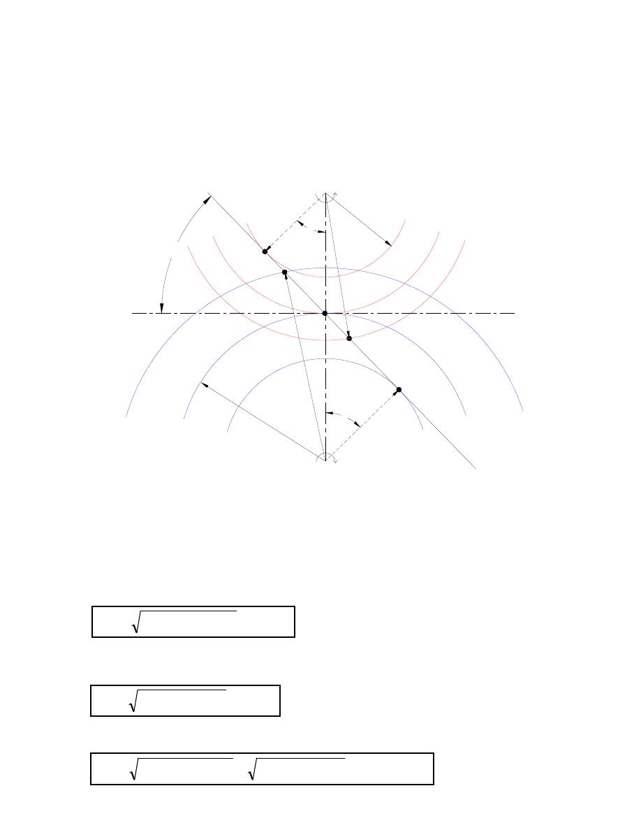
2.3.2 Contact specifications:
2.3.2.1 Path of contact (AB):
A- Beginning of contact (intersection of contact line with the addendum circle of driven).
B- End of contact (intersection of contact line with the addendum circle of driver).
Figure 8: Path of contact in spur gear.
When the pinion is the driver:
•
Path of approach AP:
•
Path of recess PB:
•
Path of contact
(
)
φ
φ
sin
cos
2
2
2
R
R
R
AP
a
−
−
=
(
)
φ
φ
sin
cos
2
2
2
r
r
r
PB
a
−
−
=
(
) (
)
φ
φ
φ
sin
)
(
cos
cos
2
2
2
2
2
2
r
R
r
r
R
R
AB
a
a
+
−
−
+
−
=

2.3.2.2 Length of arc of contact and contact ratio:
•
Arc of contact: It is the distance along the p.c from the teeth at the first point of contact
to the teeth at the last point of contact.
•
Contact ratio: is a ratio of arc of contact to the circular pitch, it represents the number of
pairs of teeth in contact
2.3.2.3 Velocity of sliding:
It is the velocity of one tooth relative to its mating tooth along the common tangent at the point
of contact. Assume C is a point of contact between A and B.
Note that at pitch point, V
s
is zero and the maximum or minimum velocity of sliding is at
maximum or minimum path of approach or path of recess.
Example 3: Two gear of 4.5 module have 24 and 33 teeth respectively. The pressure angle is
20° and each gear has a standard addendum of 1 module. Find the length of the arc of contact
and the maximum sliding velocity if the speed of the smaller gear is 120 rpm.
Solution:
m = 1/P
d
= D/T = d/t
⇒
r = (4.5 *24)/2 = 54 mm and R = (4.5 * 33)/2 = 74.25 mm
Addendum = 4.5 mm
∴
r
a
= 54 + 4.5 + 58.5 mm and R
a
= 74.75 + 4.5 = 78.75 mm
Assuming the pinion to be the driver;
φ
cos
AB
contact
of
Arc
=
φ
cos
PB
recess
of
Arc
=
φ
cos
AP
approach
of
Arc
=
p
contact
of
Arc
ratio
Contact
=
(
)
PC
V
sliding
of
Velocity
s
*
)
(
ω
Ω
+
=
Path of approach =
(
)
φ
φ
sin
R
cos
R
R
AP
2
2
2
a
−
−
=
= 11.14 mm
Path of recess =
(
)
φ
φ
sin
cos
2
2
2
r
r
r
PB
a
−
−
=
= 10.67 mm
∴ Path of contact = AP = AP + PB = 11.14 + 10.67 = 21.81 mm
∴
Arc of contact = path of contact / cos
φ
= 21.81/ cos 20° = 23.18 mm
Velocity of sliding = (
Ω
+
ω
) * PC
The maximum value of PC is the path of approach, i.e. 11.14 mm
ω
= 2
π
*120/60 = 12.57 rad/s
Ω
= 12.57*24/33 = 9.14 rad/s
∴
Maximum velocity of sliding = (12.57 + 9.14) *11.14 = 242 mm/s
Example 4:
Two mating external 4-pitch, spur gears have 18 and 42 teeth. Determine the contact ratio.
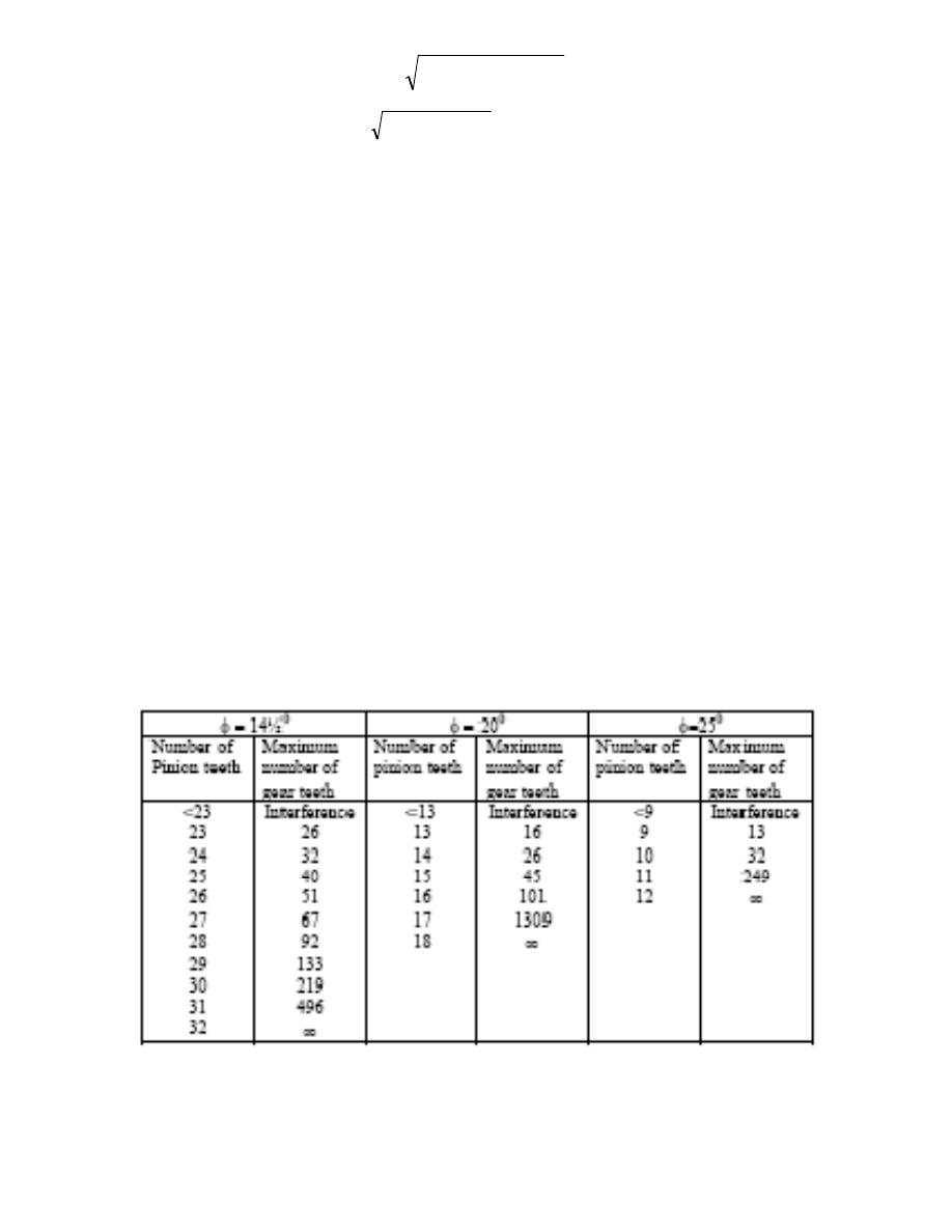
•
Interference
ü Gears with too few teeth.
ü Top of one gear digs into base of the other.
ü Use table 10.4 to check.
Example:
Two mating 20°, 4-pitch, spur gears have 12 and 42 teeth. Will they interfere?

Gears Examples:
1. Two mating spur gears have external center distance must be 7.5 in, and it is desired that the
follower (driven or gear) rotate as close to 720 RPM as possible when the driver (pinion)
rotates at 1850 RPM. Find the pitch diameters, numbers of teeth, and diametral pitch for these
two gears.
Solution:
Gear ratio or velocity ratio or speed ratio is:
e =
Ω
/
ω
= 720/1850 = 1/2.565
also
e = d/D = 1/2.565
R + r = C
⇒
D + d = 2C = 15
∴
d = 15/3.565 in
and
D = 38.475/3.565 in
D = T/P
d
and d = t/P
d
Let
T = 38.48 teeth
t = 15 teeth
and
P
d
= 3.565 teeth/in
Such a solution is not practical for it involves fractions of teeth on a gear (impossible) and it
involves a decimal diametral pitch (must undesirable).
Then multiply all of these values by a number that will make P
d
an integer. Let P
d
= 4.
∴
T = P
d
*d = 4*38.475/3.565 = 43.169
≈
43 teeth
t = 4*15/3.565 = 16.83
≈
17 teeth
then
D = T/P
d
= 10.75 in
d = t/P
d
= 4.25 in
To check
C = (D + d)/2 = 7.5 in
or
C = (T + t)/2 = 7.5 in
e = t/T = d/D =
Ω
/
ω
= 17/43 = 1/2.53
∴
Ω
= 731 rpm

2. Two external spur gears are to be mounted 5.25 in apart and have a gear ration (velocity
ratio) of 1/6. Find the data (T, t, P
d
, D, and d) for the two mentioned gears. Neither gear is to
have fewer than 15 teeth, and if
ω
= 1000 rpm, find
Ω
.
Solution:
C = (D + d)/2 = 10.5 in
∴
D + d = 10.5 in
e = 1/6 = d/D =
Ω
/
ω
= t/T
∴
D = 6*d
Therefore, d = 10.5/7 = 1.5 in
and
D = 9 in
Let
t = 15 teeth
∴
T = 6*15 = 90 teeth
and
D = T/P
d
⇒
P
d
= T/D = t/d = 10 teeth/in
Ω
/
ω
= d/D = 1/6
∴
Ω
=
ω
/6
If
ω
= 1000 rpm (for example)
∴
Ω
= 1000/6 = 167 rpm
3. A gear wheel has involutes teeth, the pressure angle being 20°. There are 18 teeth, module
12, and the wheel rotates at 250 rpm. If this wheel meshes with one having 30 teeth, find (a) the
length of the line contact, and (b) the maximum rubbing velocity. The addendum for each
wheel is equal to the module.
Solution:
(a) line of contact = path of contact = path of approach + path of recess
m = D/T = d/t ; a = m = 12 mm
∴
D = m*T = 12*30 = 360 mm
∴
R = 180 mm
d = m*t = 12*18 = 216 mm
r = 108 mm

R
a
= a + R = 12 + 180 = 192 mm
r
a
= a + r = 12 + 108 = 120 mm
∴
Path of approach =
√
(R
a
2
- R
2
*cos
2
φ
) – R*sin
φ
= 29.288 mm
Path of recess =
√
(r
a
2
- r
2
*cos
2
φ
) – r*sin
φ
= 27.095 mm
∴
Line of contact = 29.288 + 27.095 = 56.38838 mm
(b) Max. rubbing velocity = (
Ω
+
ω
) *Path of approach
e =
Ω
/
ω
= t/T
ω
= 2
π
*250/60 = 26.18 rad/s
∴
Ω
=
ω
* t/T = 15.708 rad/s
∴
Max. rubbing velocity = (26.18 + 15.708) * 29.288 = 1226.8 mm/s = 1.2268 m/s
4. A pinion of 100 mm P.C.D drives a wheel (gear) of 250 mm P.C.D. The teeth are of involute
form, pressure angle is 20°. If the addendum on each wheel is 5 mm, the pinion speed is 2000
rpm. Find for the first point of contact the sliding velocity between the teeth.
Solution:
r = 50 mm; r
a
= 55 mm; R = 125 mm; R
a
= 130 mm
At the first point of contact; means along the path of approach. Since the pinion is the driver
Path of approach =
√
(R
a
2
- R
2
*cos
2
φ
) – R*sin
φ
= 12.63 mm
ω
= 2
π
*2000/60 = 209.439 rad/s
∴
Ω
=
ω
* d/D = 83.7756 rad/s
∴
Sliding velocity = (
Ω
+
ω
) *Path of approach = (209.439 + 83.7756) * 12.63 =
3700 mm/s = 3.7 m/s
Gears Problems:
1. A spur gear set has a module of 4 mm and a velocity ratio of 2.8. The pinion has 20 teeth.
Find the number of teeth on the driven gear, the pitch diameters and the center-to-center
distance.
2. A 21 tooth spur pinion mates with a 28-tooth gear. The diametral pitch is 3 teeth/in and
the pressure angle is 20°. Find the following results: the Addendum, Dedendum, circular
pitch, base circle diameter, the length of the arc of approach, recess and the contact ratio.

3. A 15-tooth spur pinion has a module of 3 mm and runs at a speed of 1600 RPM. The
driven gear has 60 teeth. Find the speed of the driven gear, the circular pitch, and the
theoretical center-to-center distance.
4. A 17-tooth spur pinion has a diametral pitch of 8 teeth /in, runs at 1120 r/min, and drives
a gear at a speed of 544 RPM. Find the number of teeth on the gear and the center-to
center distance.
5. Two mating spur gears are required that will have a velocity ratio of 3:8. Specify the
numbers of teeth, pitch diameters, diametral pitch, and center distance for two such
gears.
6. A pinion having 20 involutes teeth of 6 module rotates at 200 rev/min and transmits 1.5
kW to a gear wheel having 50 teeth; the addendum on both wheels is 1/4 of the circular
pitch and the pressure angle is 20°. Find the length of the path of approach and of the arc
of approach.
7. Two gears have teeth of 5 module, pressure angle of 20°, the number of teeth being 15
and 20. The addendum is same in each gear. Find (a) the length of the addendum; (b) the
contact ratio; (c) the sliding velocity at the first point of contact when the smaller wheel
is driving at 3500 rev/min.
8. Two spur wheels with involutes teeth gear together externally. The pitch circle diameters
(P.C.D) are 100 and 250 mm and the smaller wheel has 16 teeth. The pressure angle is
20° and the addendum is 0.3 of the circular pitch. Determine: (a) the length of the arc of
approach if the smaller wheel is the driver, (b) the maximum velocity of sliding between
the teeth when driver rotates at 150 RPM.