
Chapter 3 - 1
ISSUES TO ADDRESS...
• How do atoms assemble into solid structures?
• How does the density of a material depend on
its structure?
• When do material properties vary with the
sample (i.e., part) orientation?
Chapter 3: The Structure of Crystalline Solids

Chapter 3 -
Learning Objectives
the difference in atomic/molecular structure between crystalline and
noncrystalline materials
unit cells for face-centered cubic, body-centered cubic, and hexagonal close-
packed crystal structures
the relationships between unit cell edge length and atomic radius for face-
centered cubic and body-centered cubic crystal structures
the densities for metals having face-centered cubic and body-centered cubic
crystal structures given their unit cell dimensions

Chapter 3 - 3
The properties of some materials are directly related
to their crystal structures. For example, pure and
undeformed magnesium and beryllium, having one crystal
structure, are much more brittle (i.e., fracture at
lower degrees of deformation) than are pure and
undeformed metals such as gold and silver that have yet
another crystal structure.
Furthermore, significant property differences
exist between crystalline and noncrystalline materials
having the same composition. For example, noncrystalline
ceramics and polymers normally are optically transparent;;
the same materials in crystalline (or semicrystalline)
form tend to be opaque or, at best,translucent.

Chapter 3 - 4
Crystalline
material is one in which the atoms are situated in a
repeating or periodic array over large atomic distances;;
that is, long-range order exists, such that upon solidification,
the atoms will position themselves in a repetitive three-
dimensional pattern, in which each atom is bonded to its
nearest-neighbor atoms.
All metals, many ceramic materials, and certain polymers
form crystalline structures under normal solidification
conditions.
For those that do not crystallize, this long-range atomic order is
absent;; these noncrystalline or amorphous materials.

Chapter 3 - 5
Some of the properties of crystalline solids depend on the
crystal structure of the material, the manner in which atoms,
ions, or molecules are spatially arranged.
There is an extremely large number of different crystal
structures all having long range atomic order;; these vary from
relatively simple structures for metals to exceedingly complex
ones, as displayed by some of the ceramic and polymeric
materials.
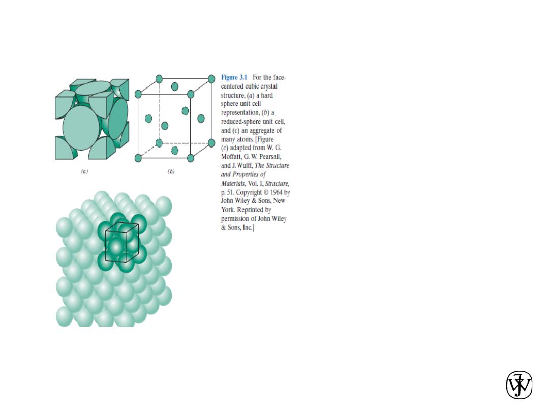
Chapter 3 -
When
describing
crystalline
structures, atoms (or ions) are thought
of as being
solid spheres having well-defined
diameters. This is termed the atomic
hard sphere model in which spheres
representing nearest-neighbor atoms
touch one another.
An example of the hard sphere model
for the atomic arrangement found in
some
of the common elemental metals is
displayed in Figure. In this particular
case
all the atoms are identical.
Sometimes the term lattice is used in
the context of crystal structures;; in this
sense
“lattice”
means
a
three-
dimensional array of points
coinciding with atom positions (or
sphere centers).
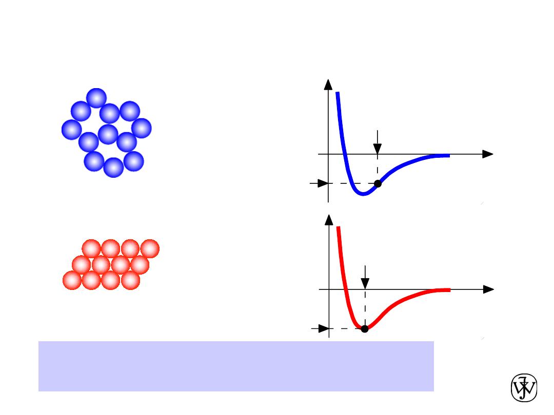
Chapter 3 - 7
• Non dense,
random
packing
• Dense,
ordered
packing
Dense, ordered packed structures tend to have
lower energies.
Energy and Packing
Energy
r
typical neighbor
bond length
typical neighbor
bond energy
Energy
r
typical neighbor
bond length
typical neighbor
bond energy
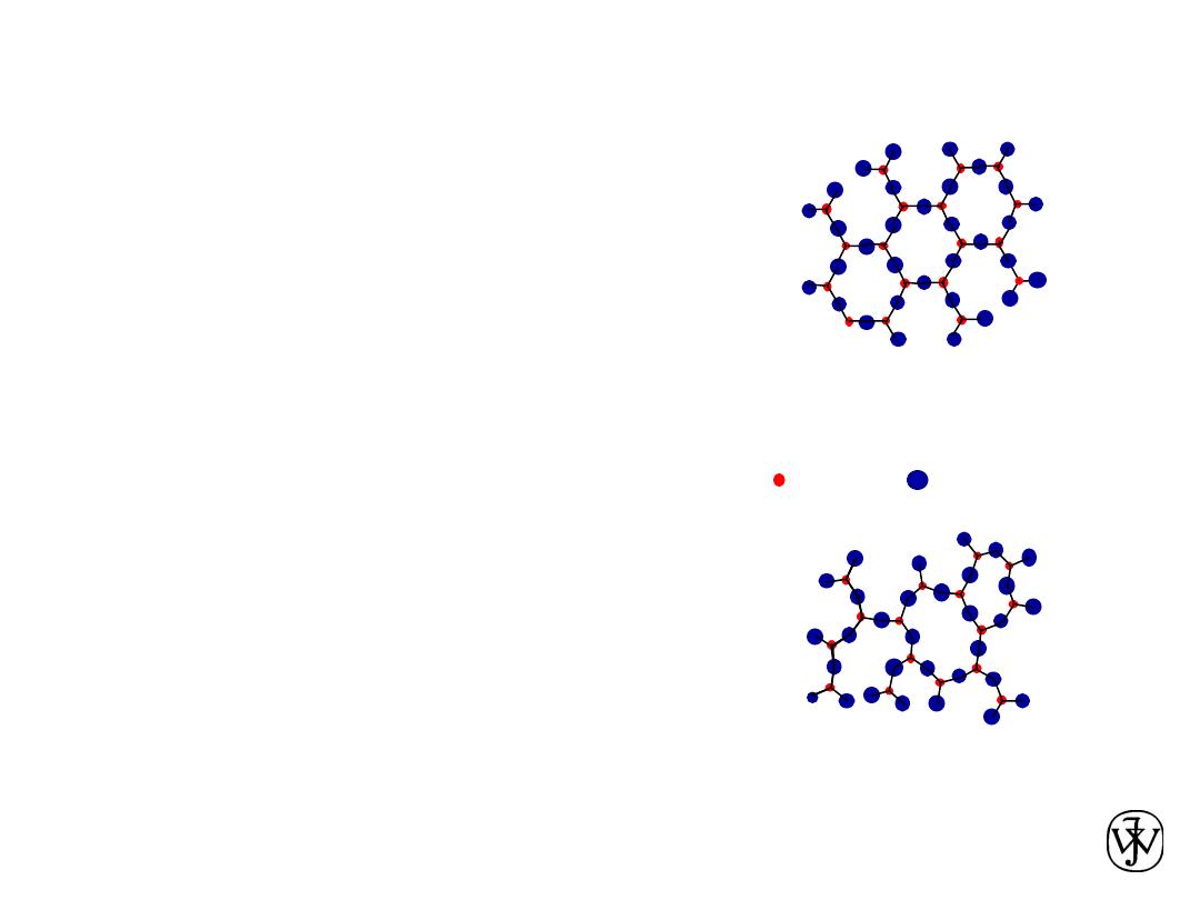
Chapter 3 - 8
• atoms pack in periodic, 3D arrays
Crystalline
materials...
-metals
-many ceramics
-some polymers
• atoms have no periodic packing
Noncrystalline
materials...
-complex structures
-rapid cooling
crystalline SiO
2
noncrystalline SiO
2
"
Amorphous
" = Noncrystalline
Adapted from Fig. 3.23(b),
Callister & Rethwisch 8e.
Adapted from Fig. 3.23(a),
Callister & Rethwisch 8e.
Materials and Packing
Si
Oxygen
• typical of:
• occurs for:
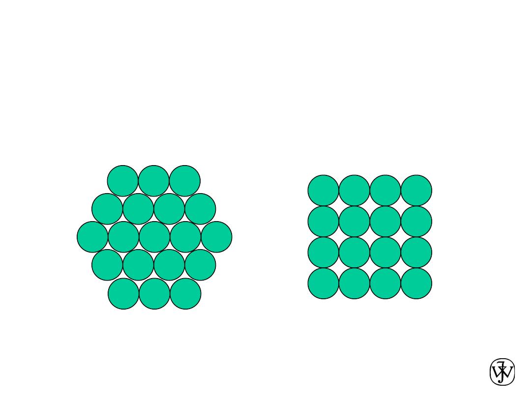
Chapter 3 - 9
Metallic Crystal Structures
• How can we stack metal atoms to minimize
empty space?
2-dimensions
vs.
Now stack these 2-D layers to make 3-D structures

Chapter 3 - 10
• Tend to be densely packed.
• Reasons for dense packing:
- Typically, only one element is present, so all atomic
radii are the same.
- Metallic bonding is not directional.
- Nearest neighbor distances tend to be small in
order to lower bond energy.
- Electron cloud shields cores from each other
• Have the simplest crystal structures.
We will examine three such structures...
Metallic Crystal Structures
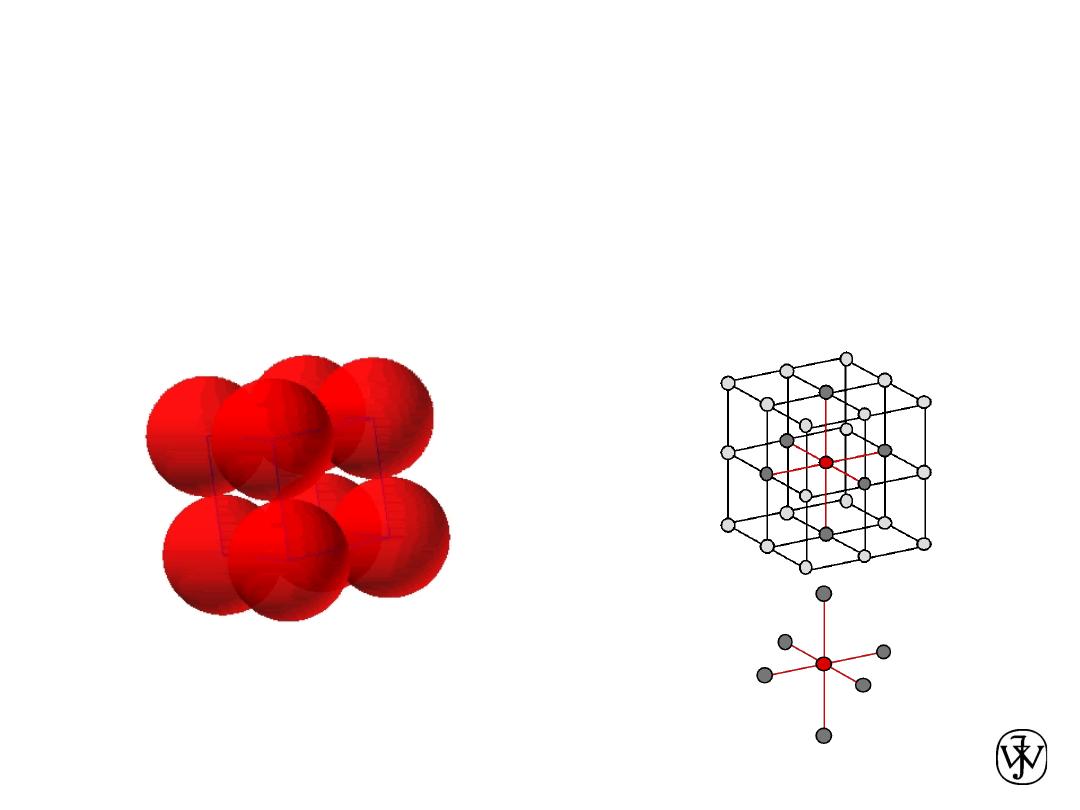
Chapter 3 - 11
• Rare due to low packing density
(only Po has this structure)
•
Close-packed directions
are cube edges.
•
Coordination #
= 6
(# nearest neighbors)
Simple Cubic Structure (SC)
Click once on image to start animation
(Courtesy P.M. Anderson)
Chapter 3 - 12
• APF for a simple cubic structure = 0.52
APF =
a3
4
3
p (0.5a) 3
1
atoms
unit cell
atom
volume
unit cell
volume
Atomic Packing Factor (APF)
APF =
Volume of atoms in unit cell*
Volume of unit cell
*assume hard spheres
Adapted from Fig. 3.24,
Callister & Rethwisch 8e.
close-packed directions
a
R=0.5a
contains 8 x 1/8 =
1 atom/unit cell
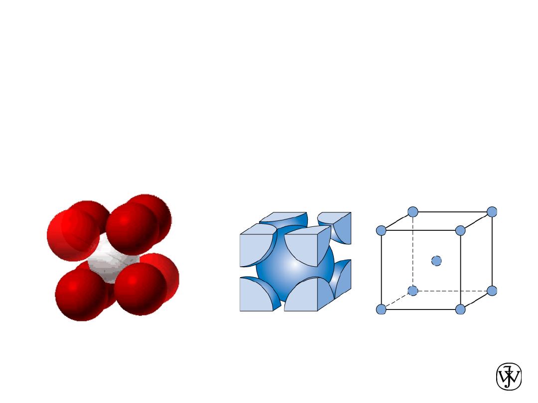
Chapter 3 - 13
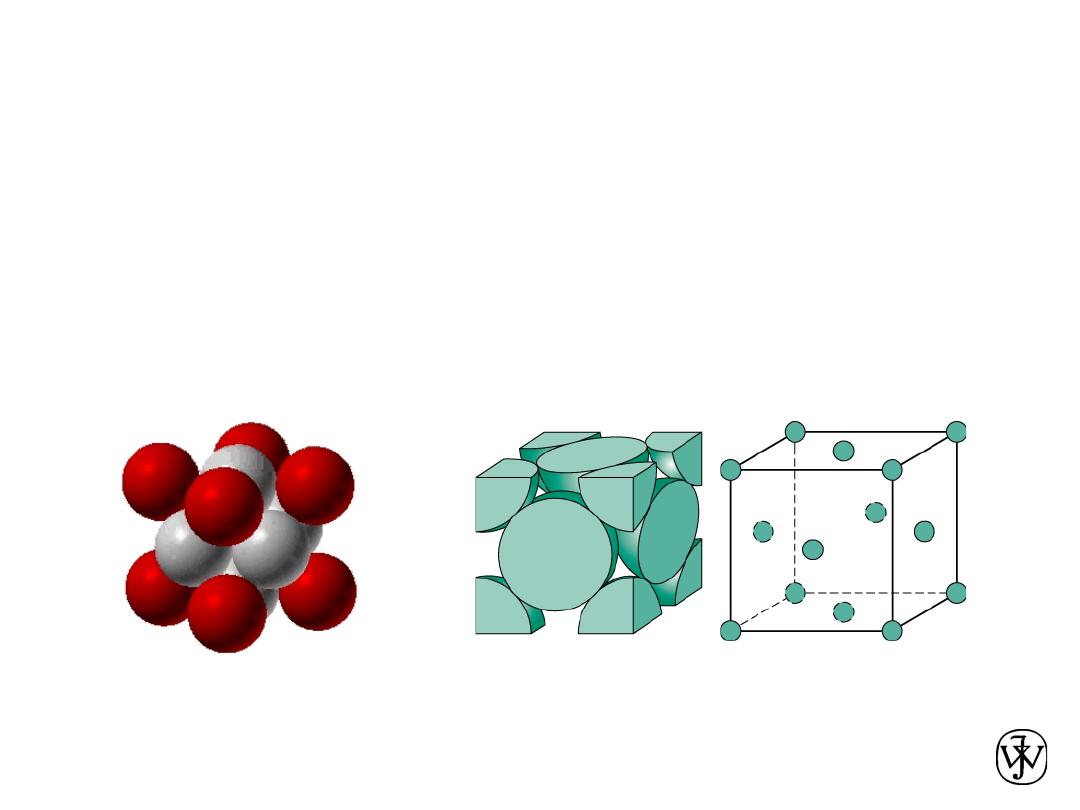
• Coordination # = 8
Adapted from Fig. 3.2,
Callister & Rethwisch 8e.
• Atoms touch each other along cube diagonals.
--Note: All atoms are identical;; the center atom is shaded
differently only for ease of viewing.
Body Centered Cubic Structure (BCC)
ex: Cr, W, Fe (
a), Tantalum, Molybdenum
2 atoms/unit cell: 1 center + 8 corners x 1/8
Click once on image to start animation
(Courtesy P.M. Anderson)
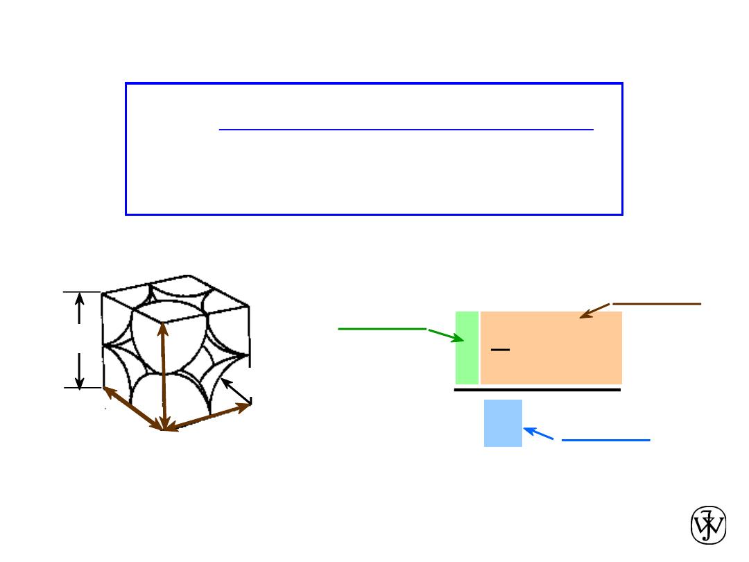
Chapter 3 - 14
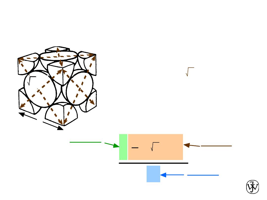
Atomic Packing Factor: BCC
a
APF =
4
3
p ( 3a/4)3
2
atoms
unit cell
atom
volume
a3
unit cell
volume
length = 4R =
Close-packed directions:
3 a
• APF for a body-centered cubic structure = 0.68
a
R
Adapted from
Fig. 3.2(a), Callister &
Rethwisch 8e.
a
2
a
3
Chapter 3 - 15
•
Coordination # = 12
Adapted from Fig. 3.1, Callister & Rethwisch 8e.
• Atoms touch each other along face diagonals.
--Note: All atoms are identical;; the face-centered atoms are shaded
differently only for ease of viewing.
Face Centered Cubic Structure (FCC)
ex: Al, Cu, Au, Pb, Ni, Pt, Ag
4 atoms/unit cell: 6 face x 1/2 + 8 corners x 1/8
Click once on image to start animation
(Courtesy P.M. Anderson)
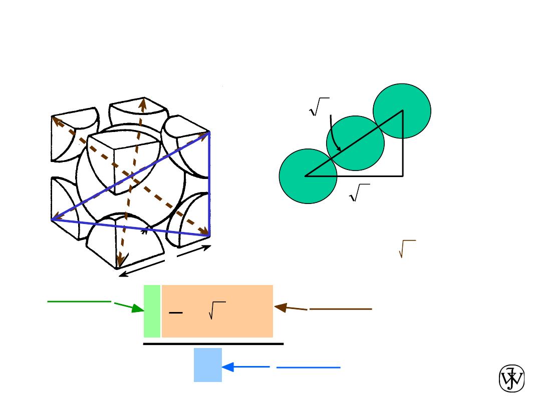
Chapter 3 - 16
• APF for a face-centered cubic structure = 0.74
Atomic Packing Factor: FCC
maximum achievable APF
APF =
4
3
p ( 2a/4)3
4
atoms
unit cell
atom
volume
a3
unit cell
volume
Close-packed directions:
length = 4R = 2 a
Unit cell contains:
6 x 1/2 + 8 x 1/8
=
4 atoms/unit cell
a
2 a
Adapted from
Fig. 3.1(a),
Callister &
Rethwisch 8e.
Chapter 3 - 17
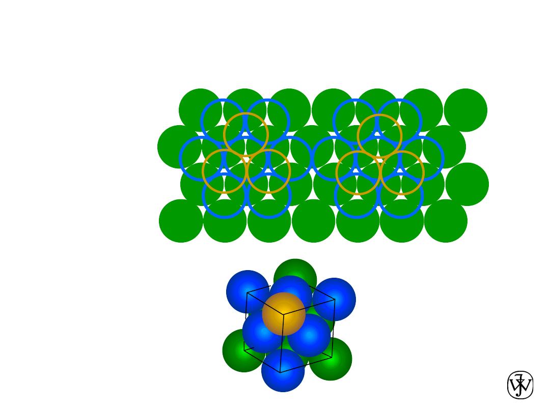
A sites
B
B
B
B
B
B
B
C sites
C
C
C
A
B
B sites
• ABCABC... Stacking Sequence
• 2D Projection
• FCC Unit Cell
FCC Stacking Sequence
B
B
B
B
B
B
B
B sites
C
C
C
A
C
C
C
A
A
B
C
Chapter 3 - 18
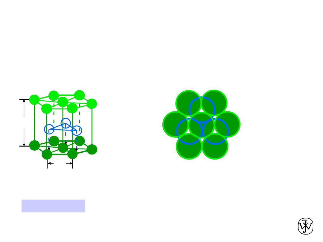
• Coordination # = 12
• ABAB... Stacking Sequence
• APF = 0.74
• 3D Projection
• 2D Projection
Adapted from Fig. 3.3(a),
Callister & Rethwisch 8e.
Hexagonal Close-Packed Structure
(HCP)
6 atoms/unit cell
ex: Cd, Mg, Ti, Zn
• c/a = 1.633
c
a
A sites
B sites
A sites
Bottom layer
Middle layer
Top layer

Chapter 3 - 19
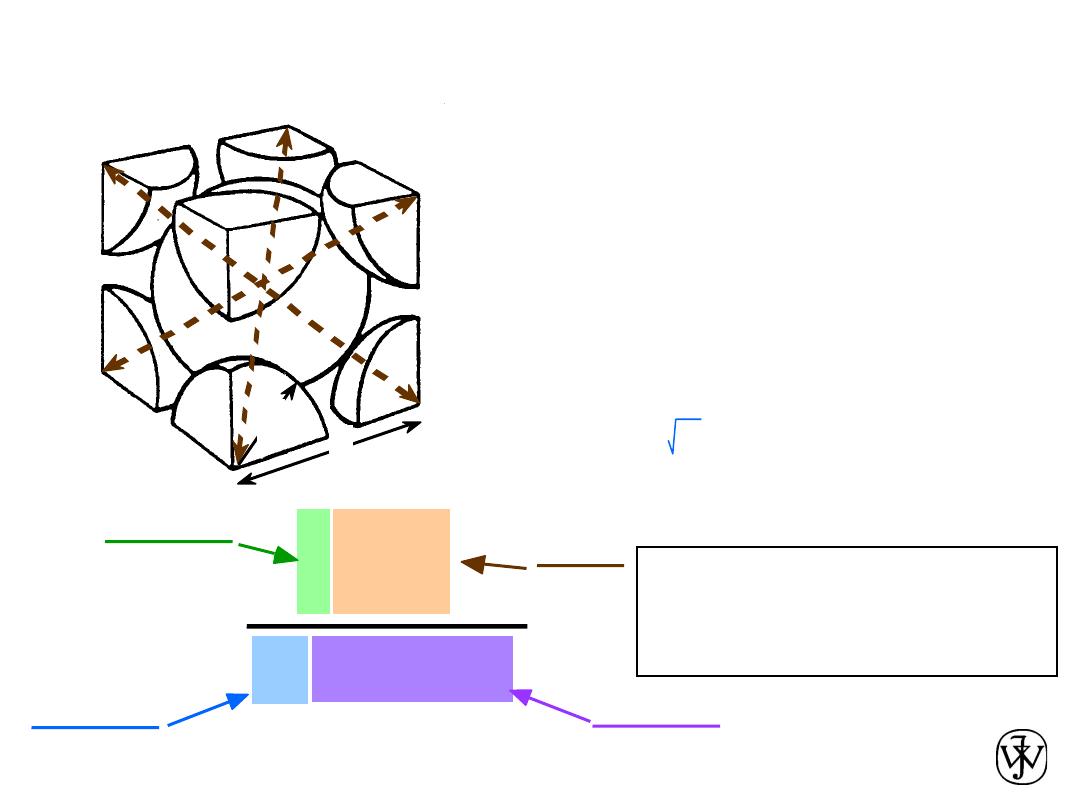
Theoretical Density,
r
where
n = number of atoms/unit cell
A = atomic weight
V
C
= Volume of unit cell = a
3
for cubic
N
A
= Avogadro’s number
= 6.022 x 10
23
atoms/mol
Density =
r =
V
C
N
A
n
A
r =
Cell
Unit
of
Volume
Total
Cell
Unit
in
Atoms
of
Mass
Chapter 3 - 20
• Ex: Cr (BCC)
A = 52.00 g/mol
R = 0.125 nm
n = 2 atoms/unit cell
r
theoretical
a = 4R/ 3 = 0.2887 nm
r
actual
a
R
r
=
a
3
52.00
2
atoms
unit cell
mol
g
unit cell
volume
atoms
mol
6.022 x 10
23
Theoretical Density,
r
= 7.18 g/cm
3
= 7.19 g/cm
3
Adapted from
Fig. 3.2(a), Callister &
Rethwisch 8e.
Chapter 3 - 21
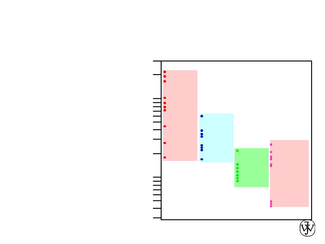
Densities of Material Classes
r
metals
>
r
ceramics
>
r
polymers
Why?
Data from Table B.1, Callister & Rethwisch, 8e.
r
(g
/cm
)
3
Graphite/
Ceramics/
Semicond
Metals/
Alloys
Composites/
fibers
Polymers
1
2
20
30
Based on data in Table B1, Callister
*GFRE, CFRE, & AFRE are Glass,
Carbon, & Aramid Fiber-Reinforced
Epoxy composites (values based on
60% volume fraction of aligned fibers
in an epoxy matrix).
10
3
4
5
0.3
0.4
0.5
Magnesium
Aluminum
Steels
Titanium
Cu,Ni
Tin, Zinc
Silver, Mo
Tantalum
Gold, W
Platinum
Graphite
Silicon
Glass -soda
Concrete
Si nitride
Diamond
Al oxide
Zirconia
HDPE, PS
PP, LDPE
PC
PTFE
PET
PVC
Silicone
Wood
AFRE*
CFRE*
GFRE*
Glass fibers
Carbon fibers
Aramid fibers
Metals
have...
• close-packing
(metallic bonding)
• often large atomic masses
Ceramics
have...
• less dense packing
• often lighter elements
Polymers
have...
• low packing density
(often amorphous)
• lighter elements (C,H,O)
Composites
have...
• intermediate values
In general
Chapter 3 - 22
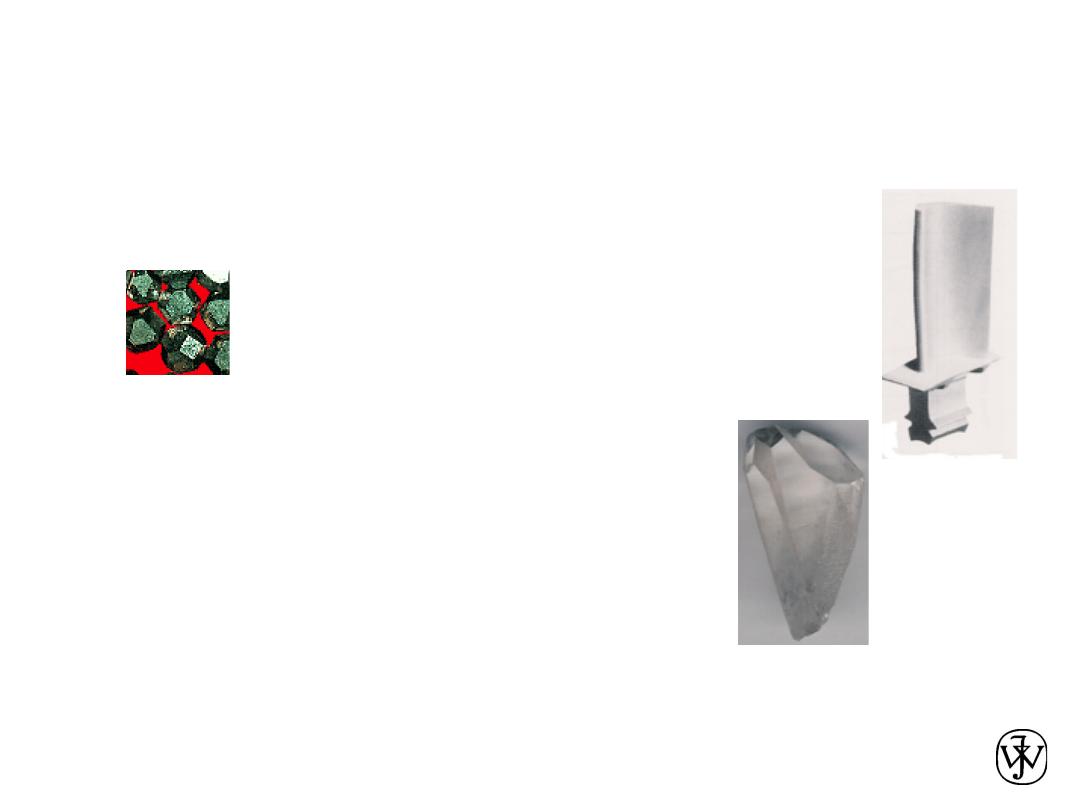
• Some engineering applications require single crystals:
• Properties of crystalline materials
often related to crystal structure.
(Courtesy P.M. Anderson)
-- Ex: Quartz fractures more easily
along some crystal planes than
others.
-- diamond single
crystals for abrasives
-- turbine blades
Fig. 8.33(c), Callister &
Rethwisch 8e. (Fig. 8.33(c)
courtesy of Pratt and
Whitney).
(Courtesy Martin Deakins,
GE Superabrasives,
Worthington, OH. Used with
permission.)
Crystals as Building Blocks
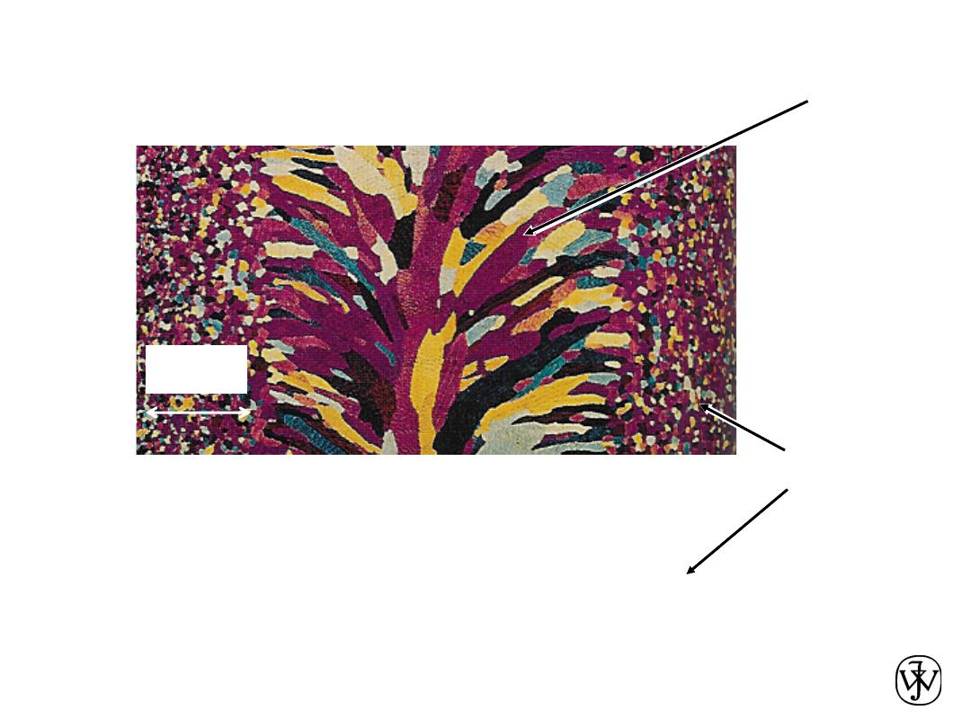
Chapter 3 - 23
• Most engineering materials are
polycrystals.
• Nb-Hf-W plate with an electron beam weld.
• Each "grain" is a single crystal.
• If grains are randomly oriented,
overall component properties are not directional.
• Grain sizes typically range from 1 nm to 2 cm
(i.e., from a few to millions of atomic layers).
Adapted from Fig. K,
color inset pages of
Callister 5e.
(Fig. K is courtesy of
Paul E. Danielson,
Teledyne Wah Chang
Albany)
1 mm
Polycrystals
Isotropic
Anisotropic
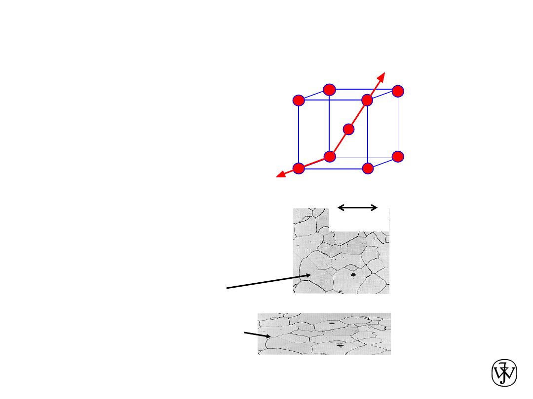
Chapter 3 - 24
• Single Crystals
-Properties vary with
direction:
anisotropic
.
-Example: the modulus
of elasticity (E) in BCC iron:
Data from Table 3.3,
Callister & Rethwisch
8e. (Source of data is
R.W. Hertzberg,
Deformation and
Fracture Mechanics of
Engineering Materials,
3rd ed., John Wiley and
Sons, 1989.)
• Polycrystals
-Properties may/may not
vary with direction.
-If grains are randomly
oriented:
isotropic
.
(E
poly iron
= 210 GPa)
-If grains are
textured
,
anisotropic.
200
µm
Adapted from Fig.
4.14(b), Callister &
Rethwisch 8e.
(Fig. 4.14(b) is courtesy
of L.C. Smith and C.
Brady, the National
Bureau of Standards,
Washington, DC [now
the National Institute of
Standards and
Technology,
Gaithersburg, MD].)
Single vs Polycrystals
E (diagonal) = 273 GPa
E (edge) = 125 GPa
Chapter 3 - 25
Polymorphism
• Two or more distinct crystal structures for the same
material (allotropy/polymorphism)
titanium
a, b-Ti
carbon
diamond, graphite
BCC
FCC
BCC
1538ºC
1394ºC
912ºC
d
-Fe
g
-Fe
a
-Fe
liquid
iron system
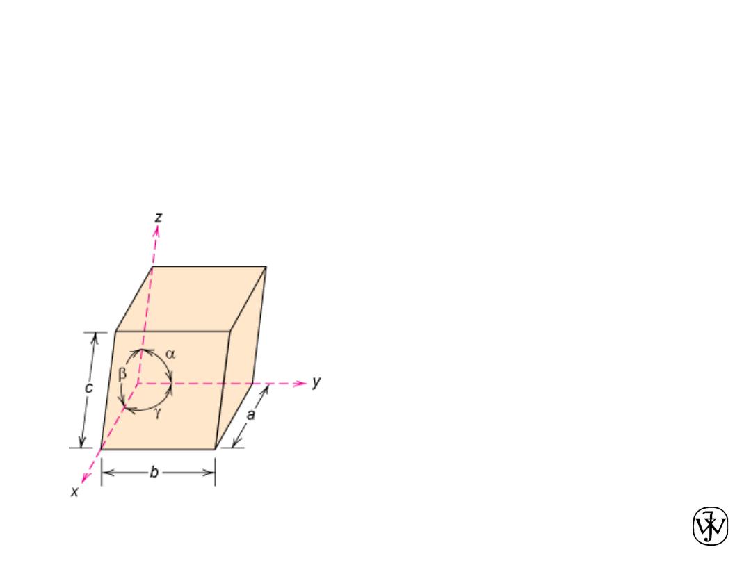
Chapter 3 - 26
Fig. 3.4, Callister & Rethwisch 8e.
Crystal Systems
7 crystal systems
14 crystal lattices
Unit cell:
smallest repetitive volume which
contains the complete lattice pattern of a crystal.
a, b, and c are the lattice constants
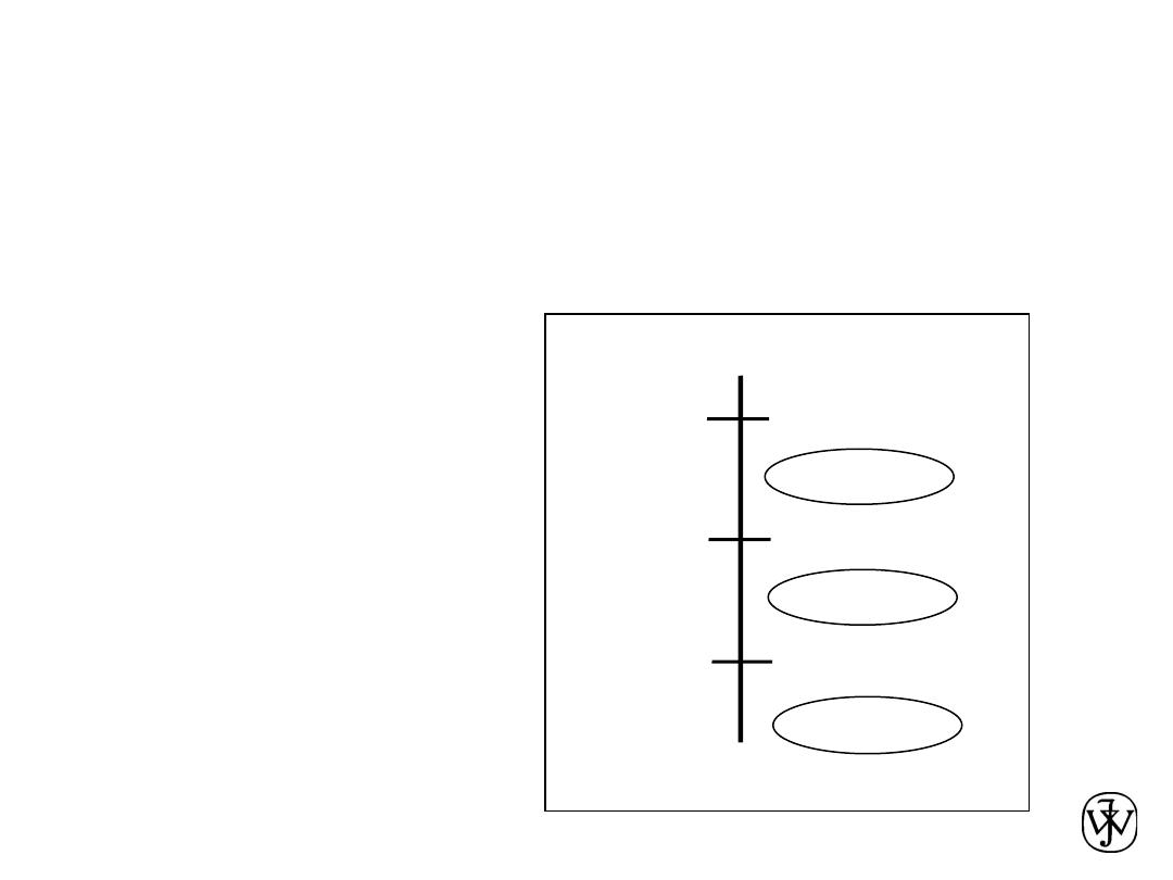
Chapter 3 - 27
Point Coordinates
Point coordinates for unit cell
center are
a/2, b/2, c/2 ½ ½ ½
Point coordinates for unit cell
corner are 111
Translation: integer multiple of
lattice constants à identical
position in another unit cell
z
x
y
a
b
c
000
111
y
z
•
2c
•
•
•
b
b
Chapter 3 - 28
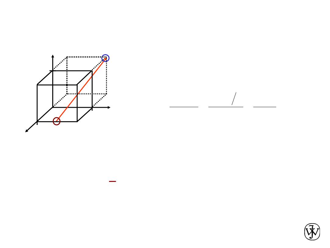
Crystallographic Directions
-4, 1, 2
families of directions <uvw>
z
x
where the overbar represents a
negative index
[ 412 ]
=>
y
Example 2:
pt. 1
x
1
=
a
, y
1
=
b
/2, z
1
= 0
pt. 2
x
2
= -
a
, y
2
=
b
, z
2
=
c
=> -2, 1/2, 1
−a − a
a
b − b 2
b
c − 0
c
pt. 2
head
pt. 1:
tail
Multiplying by 2 to eliminate the fraction
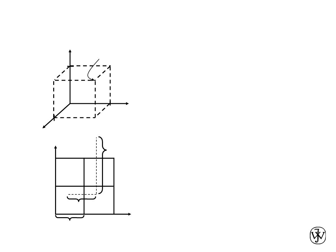
Chapter 3 - 29
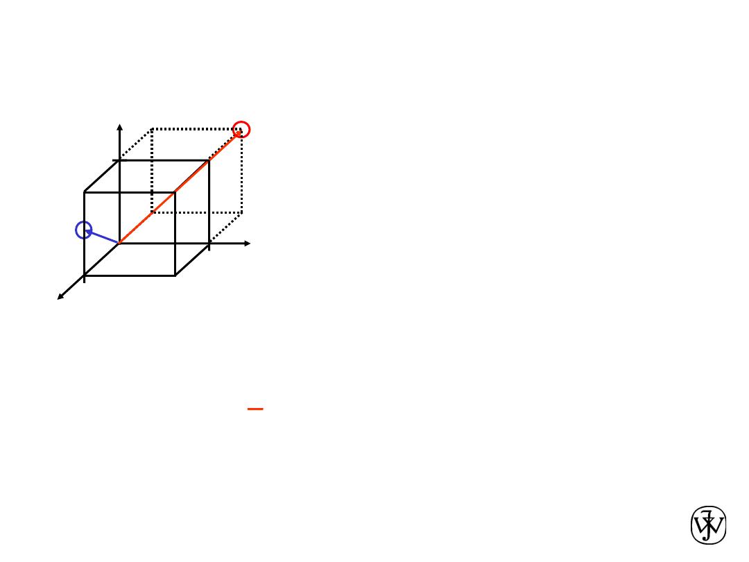
Crystallographic Directions
1. Vector repositioned (if necessary) to pass
through origin.
2. Read off projections in terms of
unit cell dimensions a, b, and c
3. Adjust to smallest integer values
4. Enclose in square brackets, no commas
[uvw]
ex:
1, 0, ½ => 2, 0, 1 => [ 201 ]
-1, 1, 1
families of directions <uvw>
z
x
Algorithm
where overbar represents a
negative index
[ 111 ]
=>
y
Chapter 3 - 30
ex: linear density of Al in [110]
direction
a = 0.405 nm
Linear Density
• Linear Density of Atoms
º LD =
a
[110]
Unit length of direction vector
Number of atoms
# atoms
length
1
3.5 nm
a
2
2
LD
-
=
=
Adapted from
Fig. 3.1(a),
Callister &
Rethwisch 8e.
Chapter 3 - 31
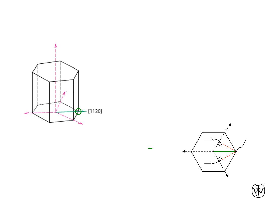
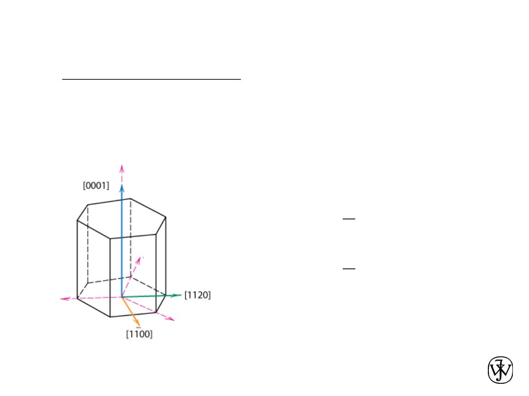
HCP Crystallographic Directions
1. Vector repositioned (if necessary) to pass
through origin.
2. Read off projections in terms of unit
cell dimensions a
1
, a
2
, a
3
, or c
3. Adjust to smallest integer values
4. Enclose in square brackets, no commas
[uvtw]
[ 1120 ]
ex:
½, ½, -1, 0 =>
Adapted from Fig. 3.8(a),
Callister & Rethwisch 8e.
dashed red lines indicate
projections onto a
1
and a
2
axes
a
1
a
2
a
3
-a
3
2
a
2
2
a
1
-
a
3
a
1
a
2
z
Algorithm
Chapter 3 - 32
HCP Crystallographic Directions
• Hexagonal Crystals
– 4 parameter Miller-Bravais lattice coordinates are
related to the direction indices (i.e., u'v'w') as
follows.
=
=
=
'
w
w
t
v
u
)
v
u
( +
-
)'
u
'
v
2
(
3
1
-
)'
v
'
u
2
(
3
1
-
=
]
uvtw
[
]
'
w
'
v
'
u
[
®
Fig. 3.8(a), Callister & Rethwisch 8e.
-
a
3
a
1
a
2
z
Chapter 3 - 33
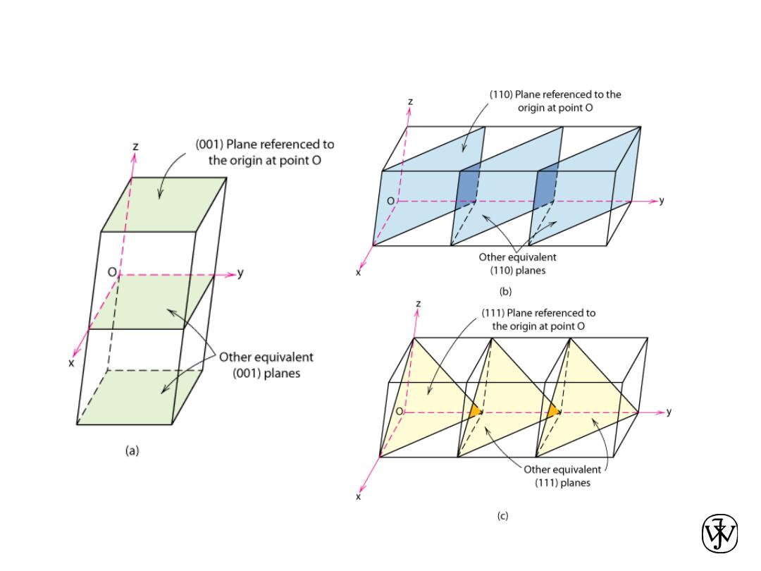
Crystallographic Planes
Adapted from Fig. 3.10,
Callister & Rethwisch 8e.

Chapter 3 - 34
Crystallographic Planes
• Miller Indices: Reciprocals of the (three) axial
intercepts for a plane, cleared of fractions &
common multiples. All parallel planes have
same Miller indices.
• Algorithm
1. Read off intercepts of plane with axes in
terms of a, b, c
2. Take reciprocals of intercepts
3. Reduce to smallest integer values
4. Enclose in parentheses, no
commas i.e.,
(hkl)
Chapter 3 - 35
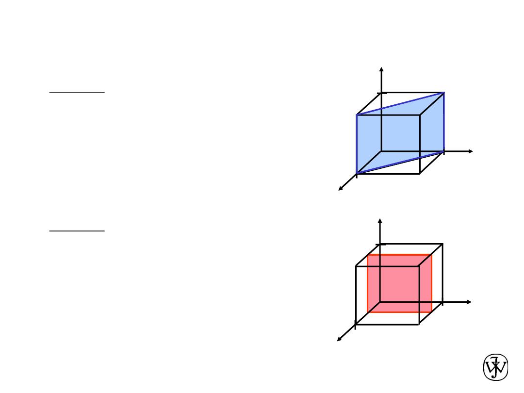
Crystallographic Planes
z
x
y
a
b
c
4. Miller Indices (110)
example
a
b
c
z
x
y
a
b
c
4. Miller Indices (100)
1. Intercepts
1 1
¥
2. Reciprocals
1/1 1/1 1/
¥
1 1 0
3. Reduction
1 1 0
1. Intercepts
1/2
¥
¥
2. Reciprocals
1/½ 1/
¥ 1/¥
2 0 0
3. Reduction
2 0 0
example
a
b
c
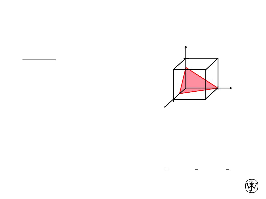
Chapter 3 - 36
Crystallographic Planes
z
x
y
a
b
c
•
•
•
4. Miller Indices (634)
example
1. Intercepts
1/2 1 3/4
a b c
2. Reciprocals
1/½ 1/1 1/¾
2
1 4/3
3. Reduction
6
3 4
(001)
(010),
Family of Planes {hkl}
(100), (010),
(001),
Ex: {100} = (100),
Chapter 3 - 37
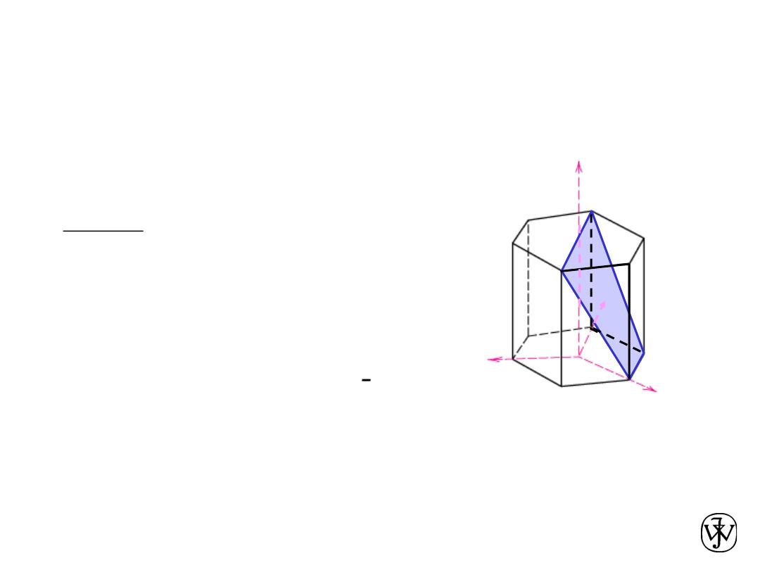
Crystallographic Planes (HCP)
• In hexagonal unit cells the same idea is used
example
a
1
a
2
a
3
c
4. Miller-Bravais Indices
(1011)
1. Intercepts
1
¥
-1
1
2. Reciprocals
1 1/
¥
1 0
-1
-1
1
1
3. Reduction
1 0
-1
1
a
2
a
3
a
1
z
Adapted from Fig. 3.8(b),
Callister & Rethwisch 8e.

Chapter 3 - 38
Crystallographic Planes
•
We want to examine the atomic packing of
crystallographic planes
•
Iron foil can be used as a catalyst. The
atomic packing of the exposed planes is
important.
a) Draw (100) and (111) crystallographic planes
for Fe.
b) Calculate the planar density for each of these
planes.
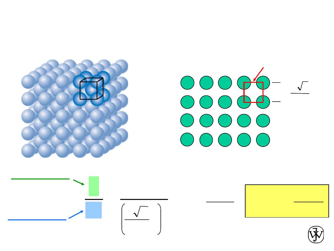
Chapter 3 - 39
Planar Density of (100) Iron
Solution: At T < 912ºC iron has the BCC structure.
(100)
Radius of iron R = 0.1241 nm
R
3
3
4
a =
Adapted from Fig. 3.2(c), Callister & Rethwisch 8e.
2D repeat unit
=
Planar Density =
a
2
1
atoms
2D repeat unit
=
nm
2
atoms
12.1
m
2
atoms
= 1.2 x 10
19
1
2
R
3
3
4
area
2D repeat unit
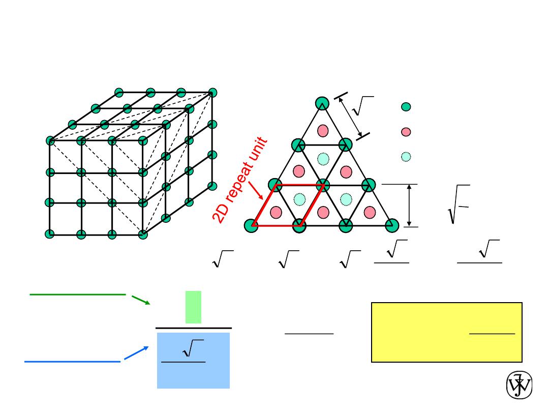
Chapter 3 - 40
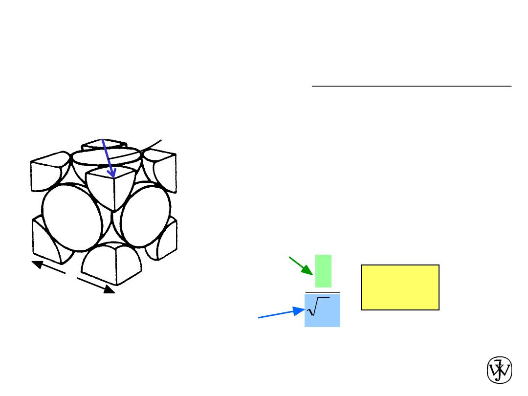
Planar Density of (111) Iron
Solution (cont): (111) plane
1 atom in plane/ unit surface cell
3
3
3
2
2
R
3
16
R
3
4
2
a
3
ah
2
area
=
÷÷
ø
ö
çç
è
æ
=
=
=
atoms in plane
atoms above plane
atoms below plane
a
h
2
3
=
a
2
1
=
=
nm
2
atoms
7.0
m
2
atoms
0.70 x 10
19
3
2
R
3
16
Planar Density =
atoms
2D repeat unit
area
2D repeat unit
Chapter 3 - 41
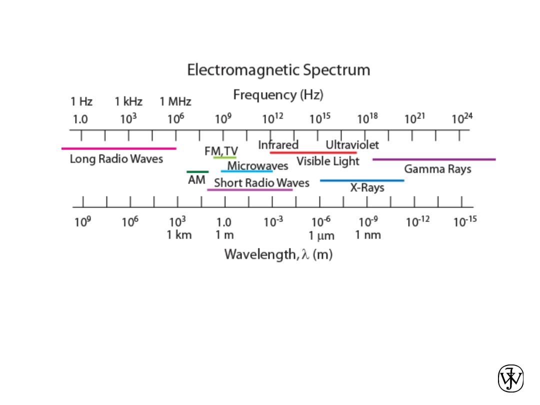
X-Ray Diffraction
• Diffraction gratings must have spacings comparable to
the wavelength of diffracted radiation.
• Can’t resolve spacings
< l
• Spacing is the distance between parallel planes of
atoms.
Chapter 3 - 42
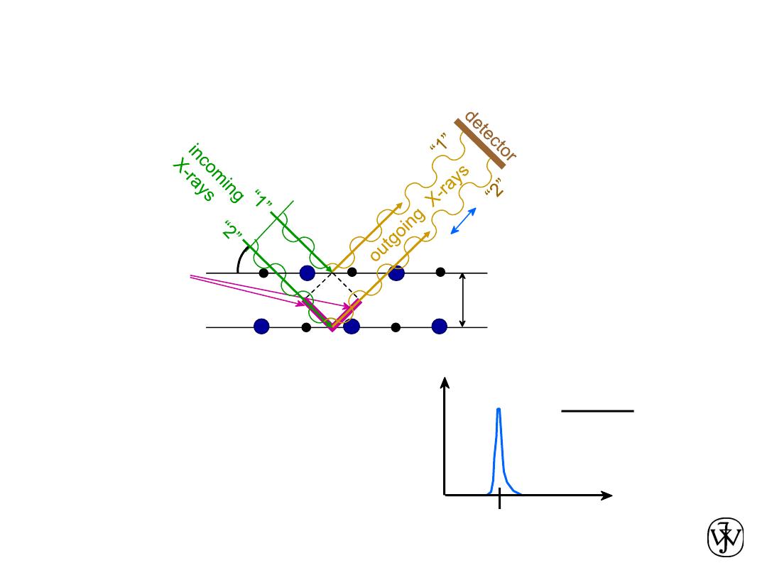
X-Rays to Determine Crystal Structure
X-ray
intensity
(from
detector)
q
qc
d
=
n
l
2 sin
qc
Measurement of
critical angle,
q
c
,
allows computation of
planar spacing, d.
• Incoming X-rays
diffract
from crystal planes.
Adapted from Fig. 3.20,
Callister & Rethwisch 8e.
reflections must
be in phase for
a detectable signal
spacing
between
planes
d
q
l
q
extra
distance
travelled
by wave “2”
Chapter 3 - 43
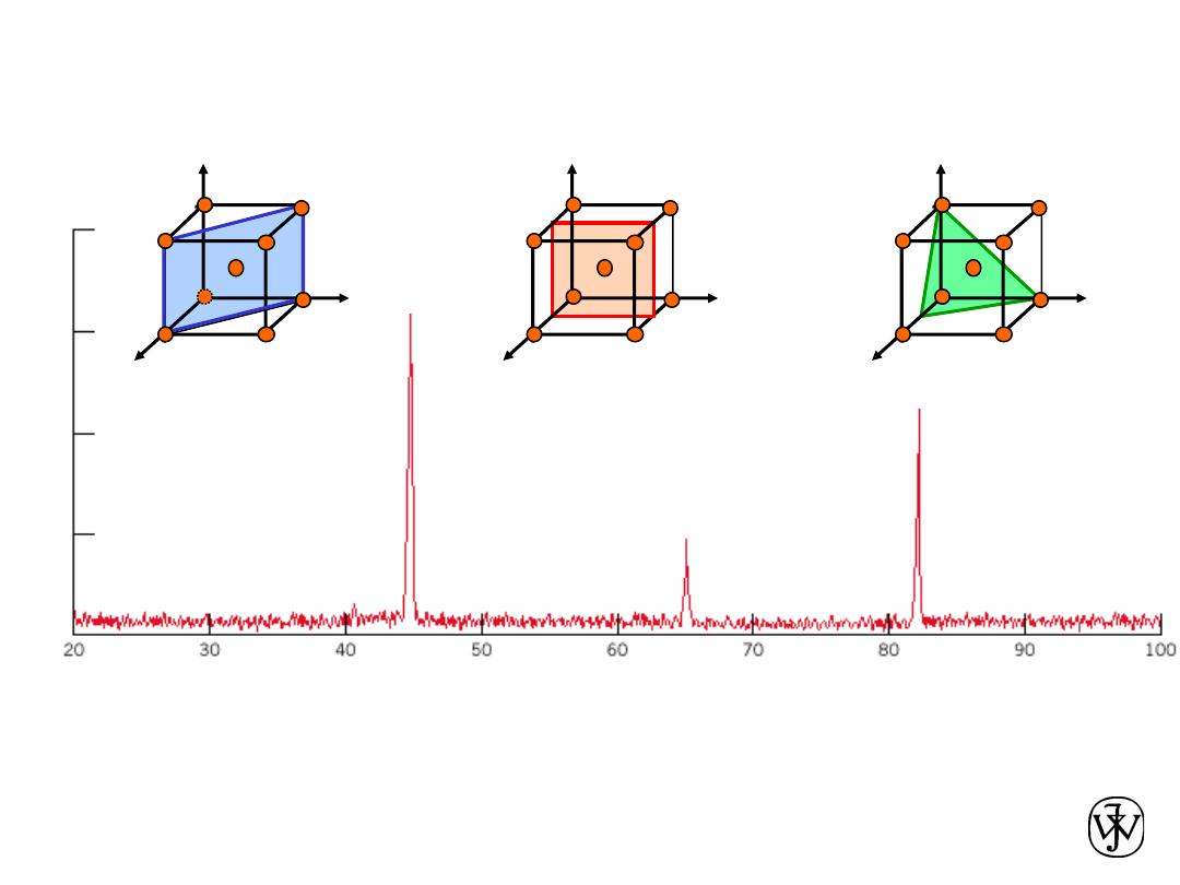
X-Ray Diffraction Pattern
Adapted from Fig. 3.22, Callister 8e.
(110)
(200)
(211)
z
x
y
a
b
c
Diffraction angle 2
q
Diffraction pattern for polycrystalline
a-iron (BCC)
In
te
nsi
ty
(r
el
at
ive
)
z
x
y
a
b
c
z
x
y
a
b
c

Chapter 3 - 44
SUMMARY
• Atoms may assemble into
crystalline
or
amorphous
structures.
• We can predict the
density
of a material, provided we
know the
atomic weight
,
atomic radius
, and
crystal
geometry
(e.g., FCC, BCC, HCP).
• Common metallic crystal structures are
FCC
,
BCC
, and
HCP
.
Coordination number
and
atomic packing factor
are the same for both FCC and HCP crystal structures.
•
Crystallographic points
,
directions
and
planes
are
specified in terms of indexing schemes.
Crystallographic directions and planes are related
to
atomic linear densities
and
planar densities
.

Chapter 3 - 45
• Some materials can have more than one crystal
structure. This is referred to as
polymorphism
(or
allotropy
).
SUMMARY
• Materials can be
single crystals
or
polycrystalline
.
Material properties generally vary with single crystal
orientation (i.e., they are
anisotropic
), but are generally
non-directional (i.e., they are
isotropic
) in polycrystals
with randomly oriented grains.
•
X-ray diffraction
is used for crystal structure and
interplanar spacing
determinations.