
INTRODUCTION TO POWER
ELECTRONICS CONVERTERS
AC to DC Converters
2016-2017
Part II

Single Phase Full Wave Bridge Controlled Rectifier
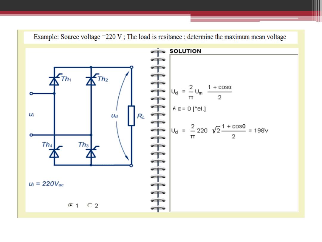
The Load is Resistive and firing angle α =0

Single Phase Full Wave Bridge Controlled Rectifier
The Load is Resistive and firing angle α = π /4
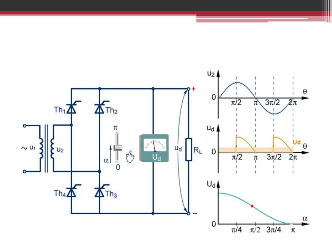
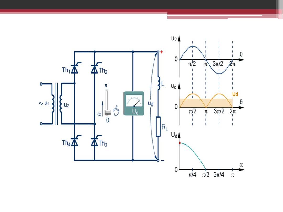
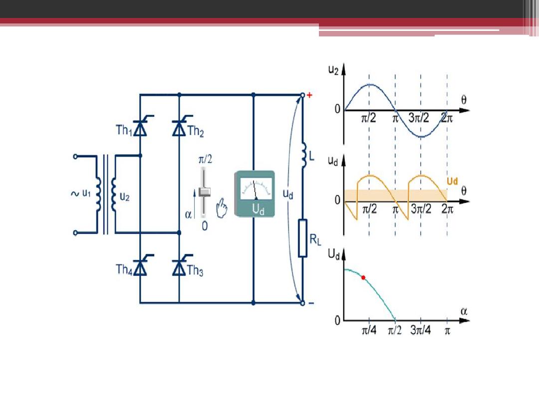
Single Phase Full Wave Bridge Controlled Rectifier
The Load is Resistive and firing angle α = π /2

Single Phase Full Wave Bridge Controlled Rectifier
The Load is Resistive and firing angle α = 3 π /4
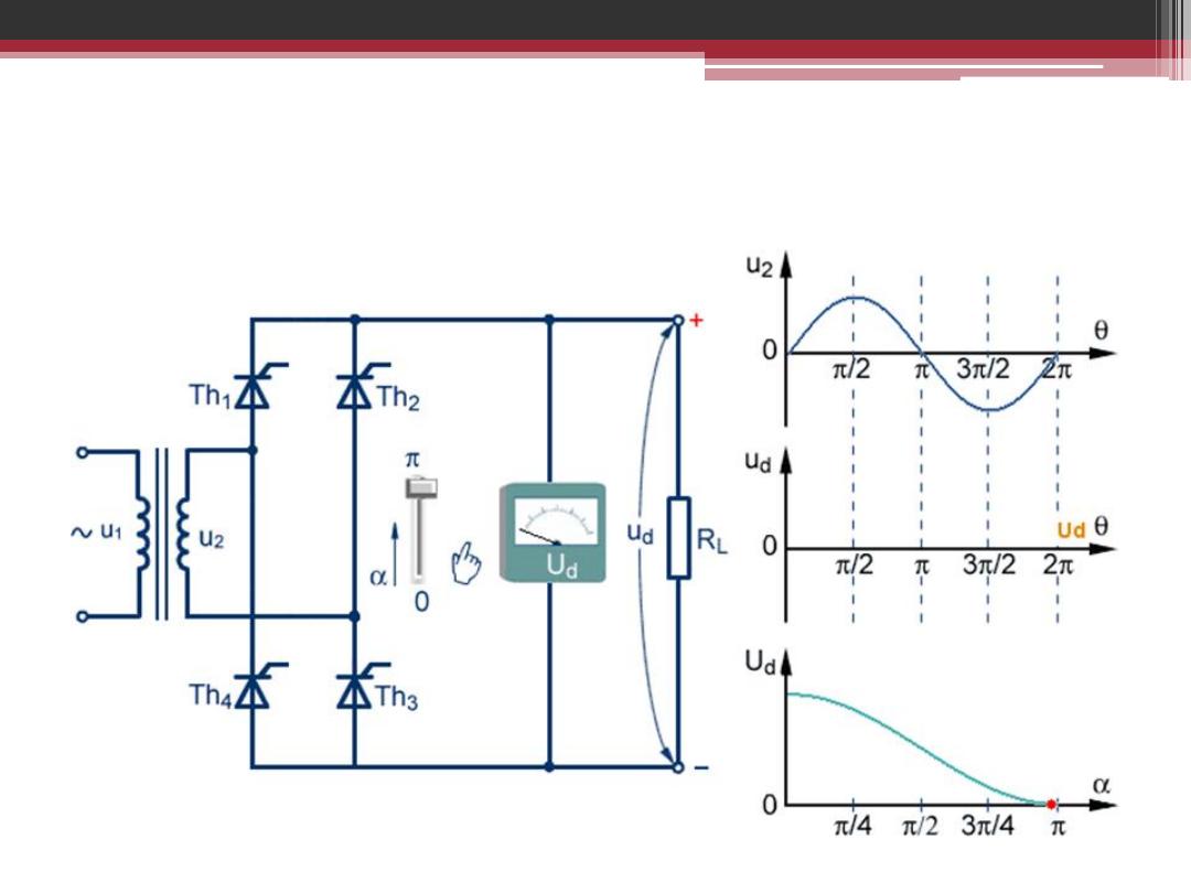
Single Phase Full Wave Bridge Controlled Rectifier
The Load is Resistive and firing angle α = π

Single Phase Full Wave Bridge Controlled Rectifier
The Load is highly inductive with no gates signals
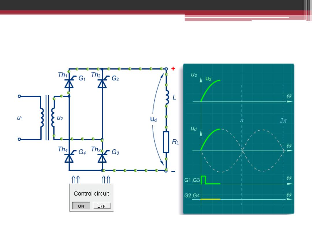
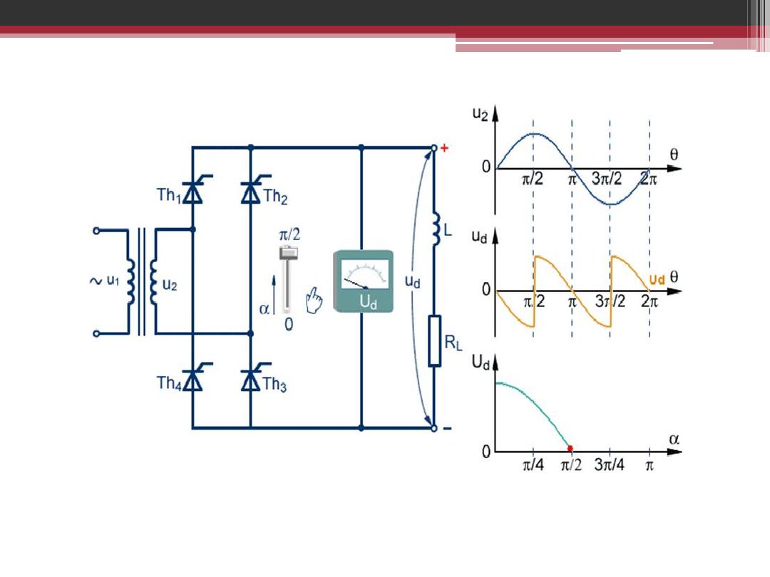
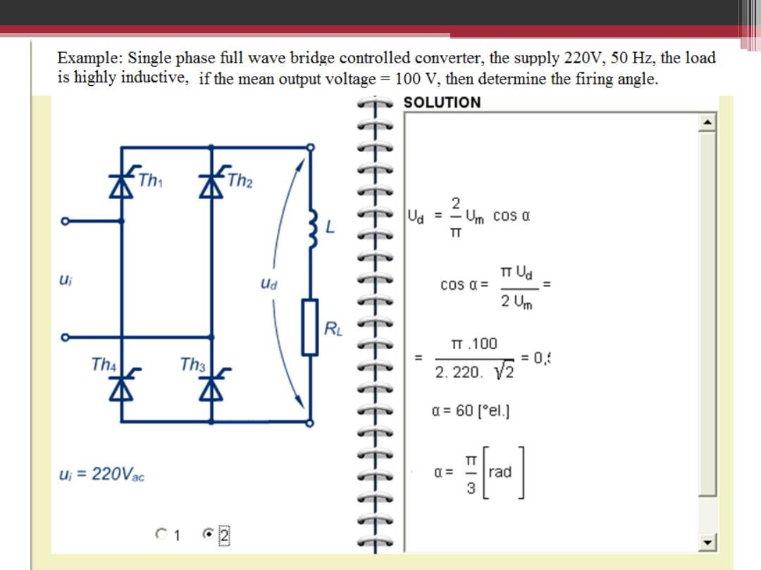
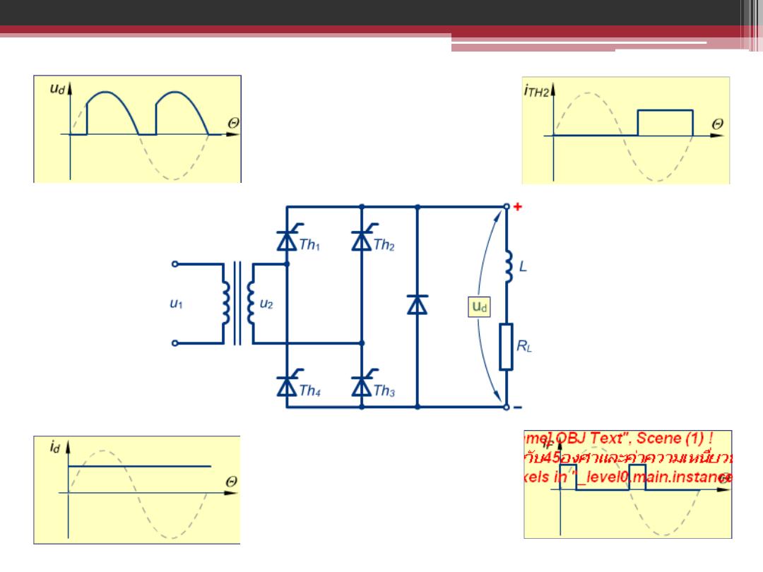
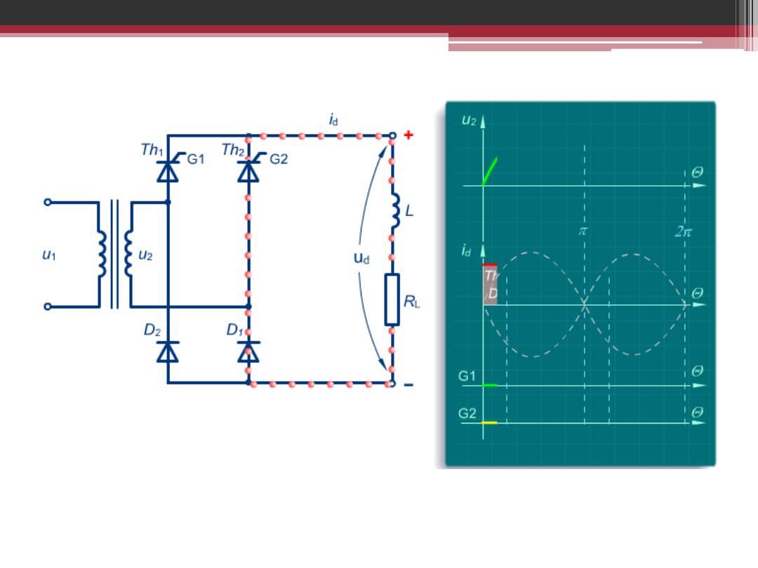
Single Phase Full Wave Bridge Controlled Rectifier
The Load is highly inductive with gates signals at α
1
=
α
3
=
0
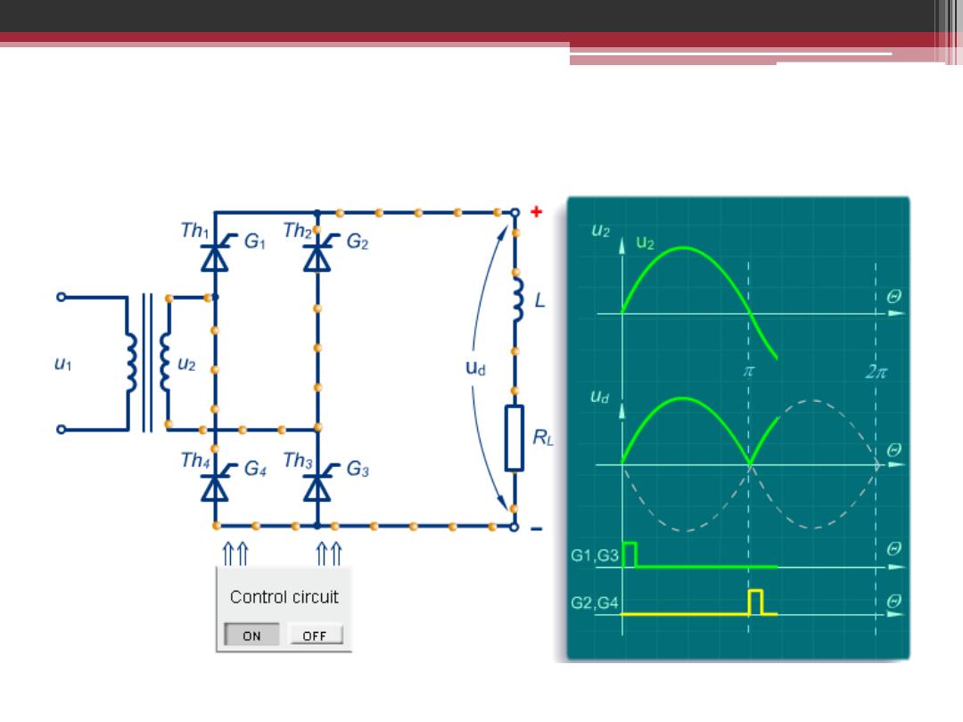
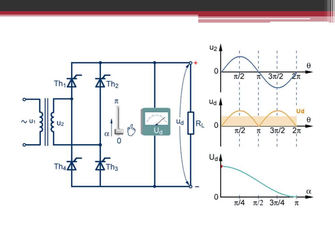
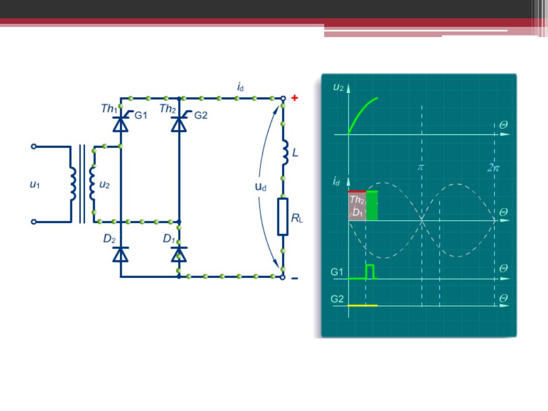
Single Phase Full Wave Bridge Controlled Rectifier
The Load is highly inductive with gates signals at α
2
=
α
4
= π

Single Phase Full Wave Bridge Controlled Rectifier
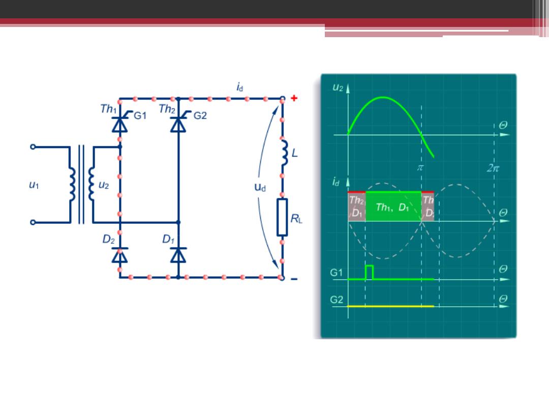
The Load is highly inductive with gates signals at α
1
= 0
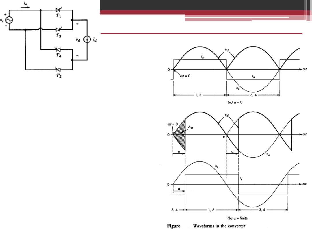
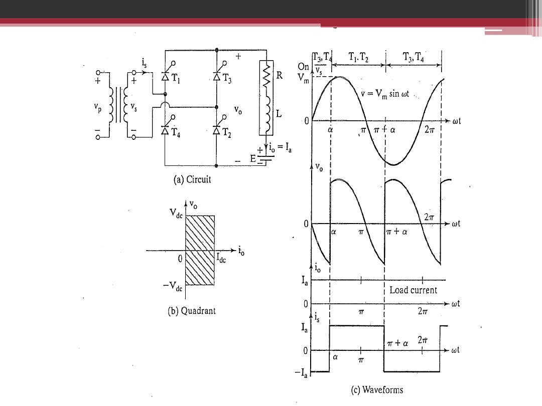
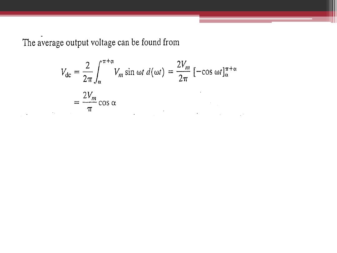
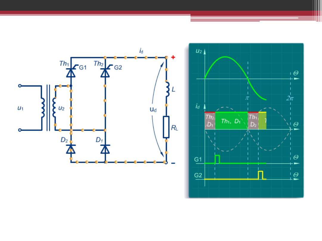
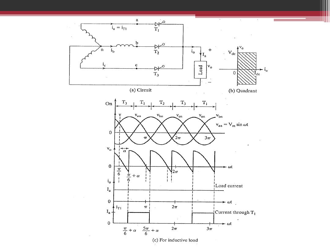
Thyristor Converter Waveforms
Single Phase
Assumptions: purely dc current I
d
a:
delay angle or firing angle
Prior to
w
t
=0, current is flowing through
3 and 4, and
v
d
= -
v
s
Beyond
w
t
=0, thyristors 1 and 2 become
forward biased,.
v
d
becomes negative between 0 and
a
as a consequence of the delay angle
At
w
t=
a
, gate pulse applied and current
commutation from thyristors 3 and 4 to 1
and 2 is instantaneous and
v
d
=
v
s
Thyristors 1 and 2 will keep conducting
until 3 and 4 are fired
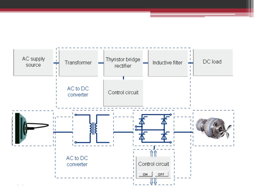
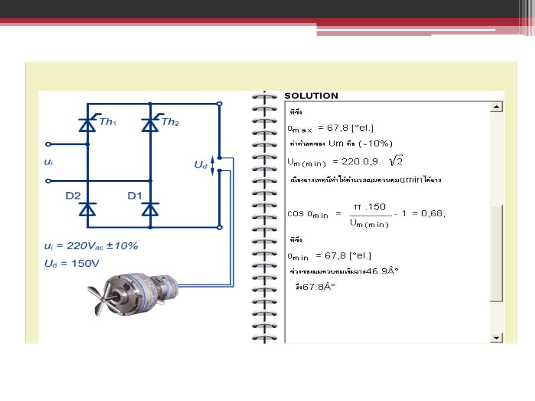
Speed Control of DC Motor Using Single Phase Full
Wave Bridge Controlled Rectifier

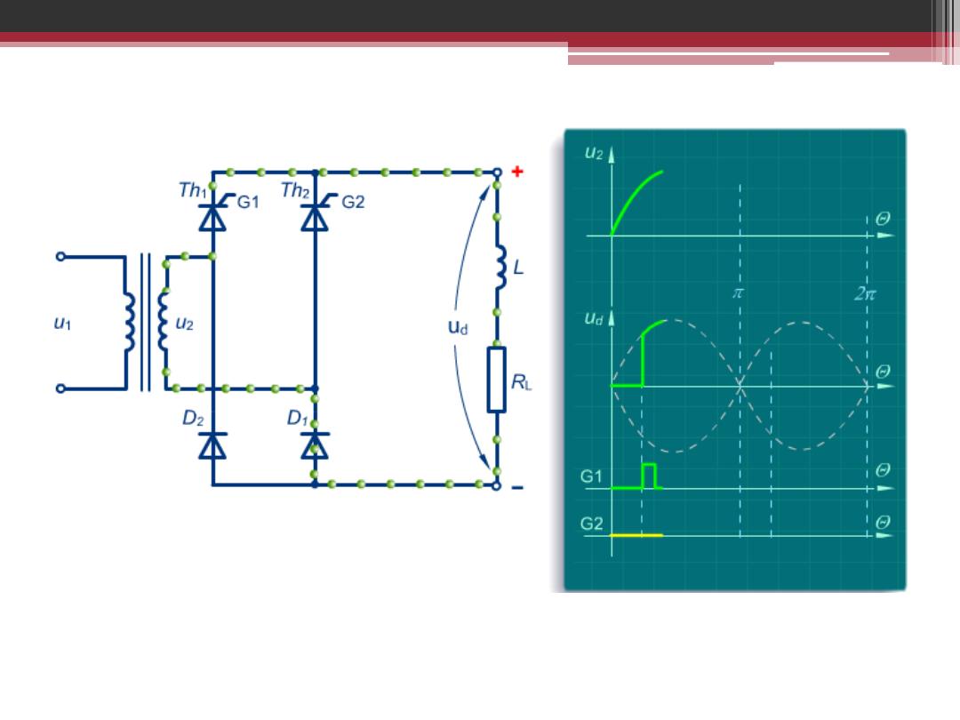
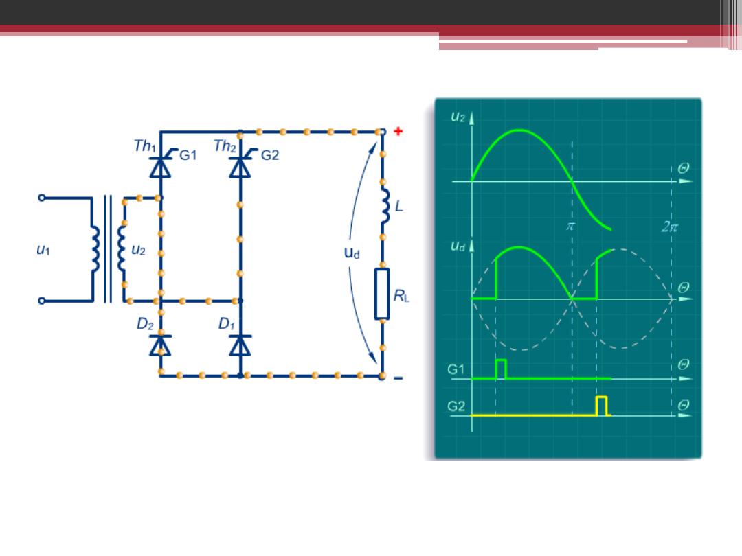
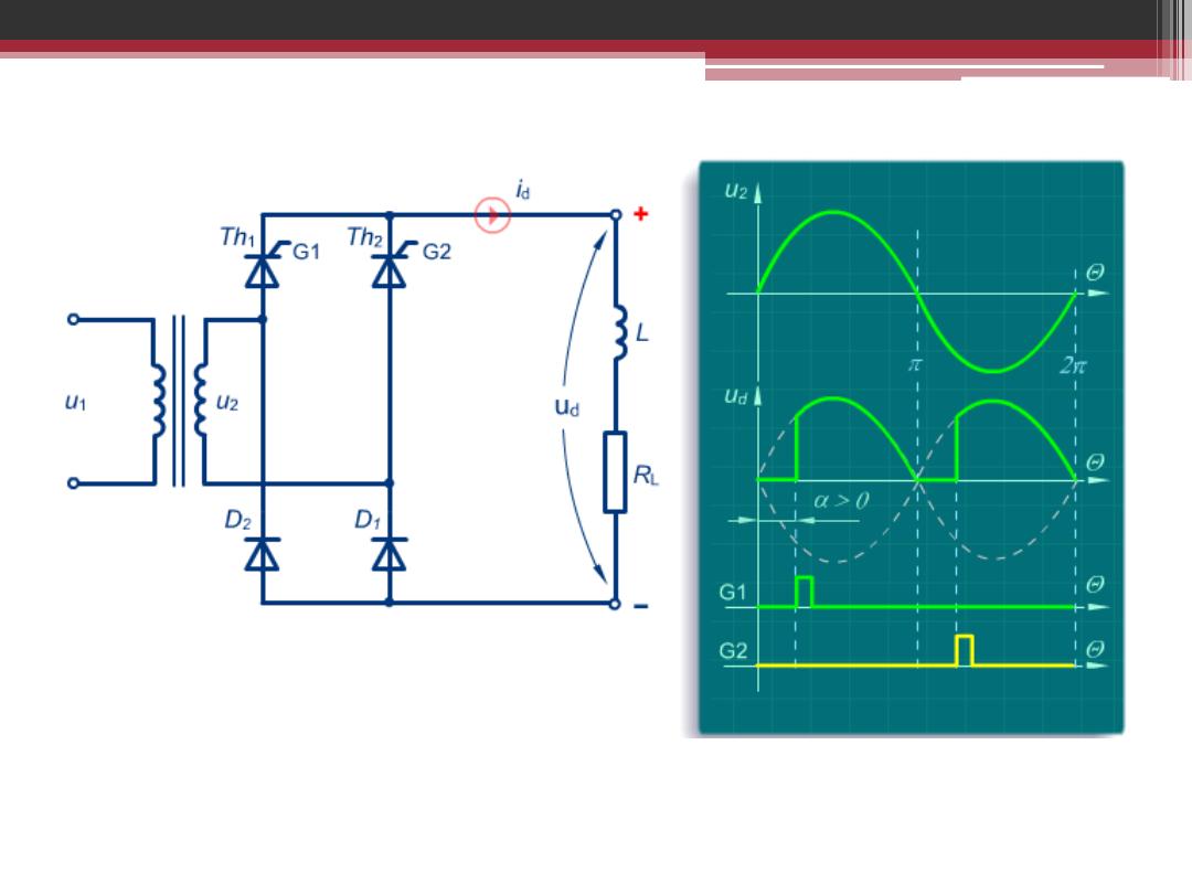
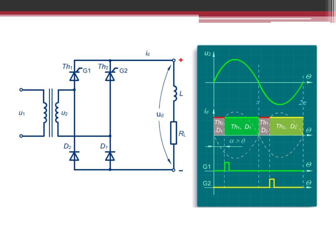
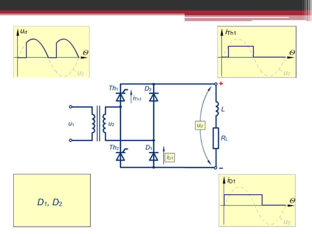
Semi-Controlled Bridge
Rectifier


Three Phase Half Controlled
Bridge Rectifier
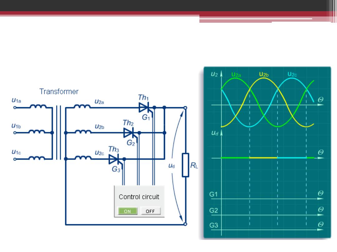
Three Phase Half Controlled Bridge Rectifier
With Resistive Load
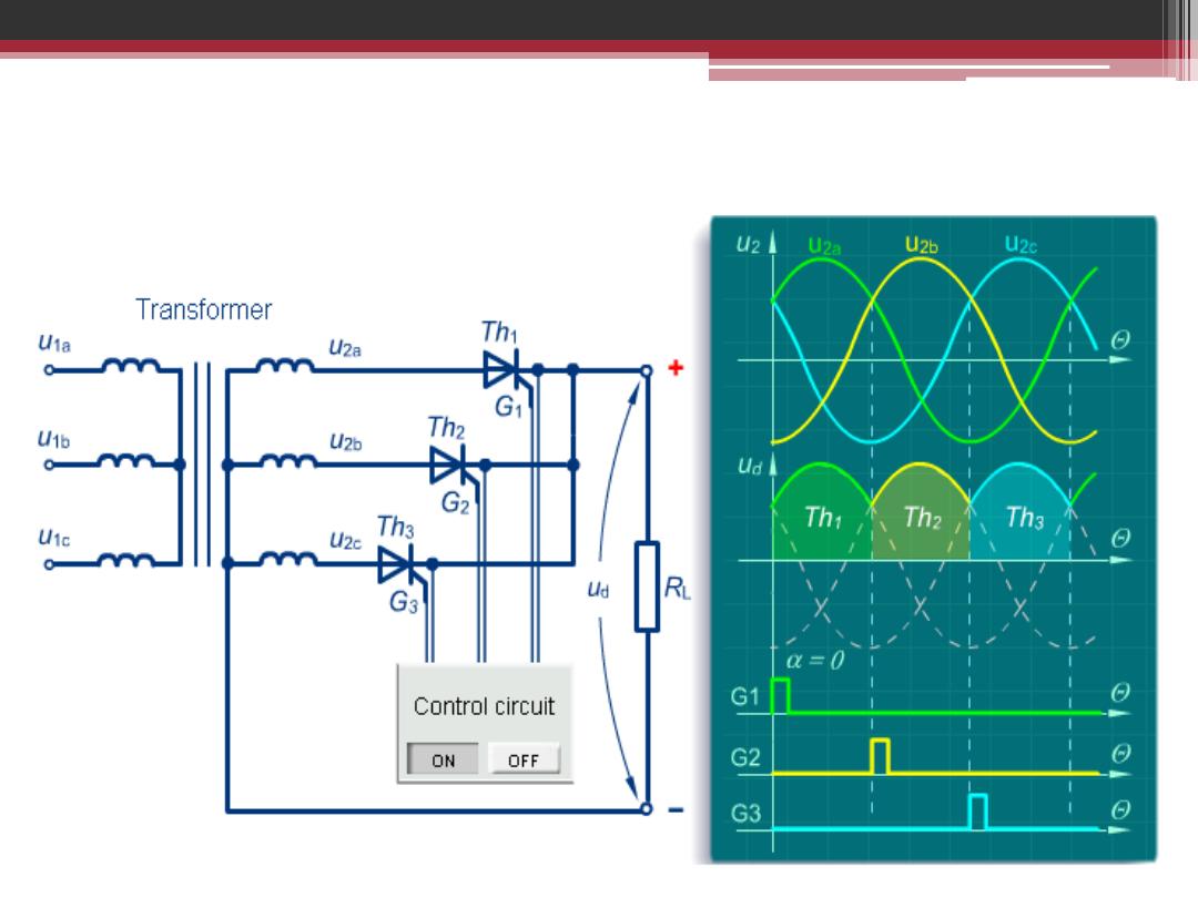
Three Phase Half Controlled Bridge Rectifier
With Resistive Load for α = 0
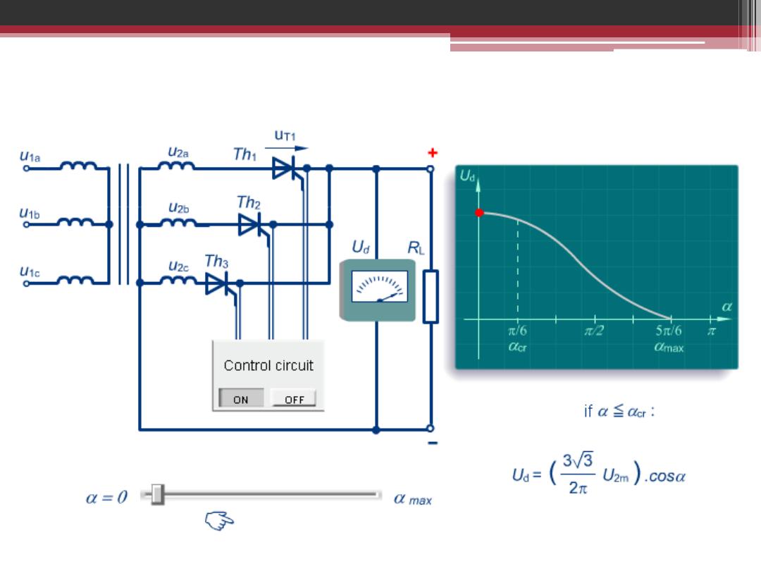
Three Phase Half Controlled Bridge Rectifier
With Resistive Load for α = 0
Three Phase Half Controlled Bridge Rectifier
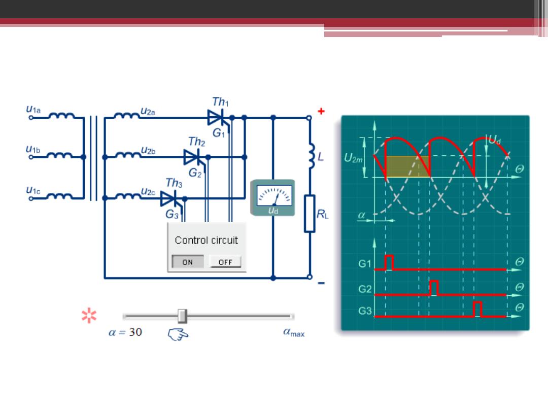
With Inductive Load for α = 30
Three Phase Half Controlled Bridge Rectifier
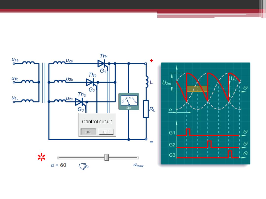
With Inductive Load for α = 60
Three Phase Half Controlled Bridge Rectifier
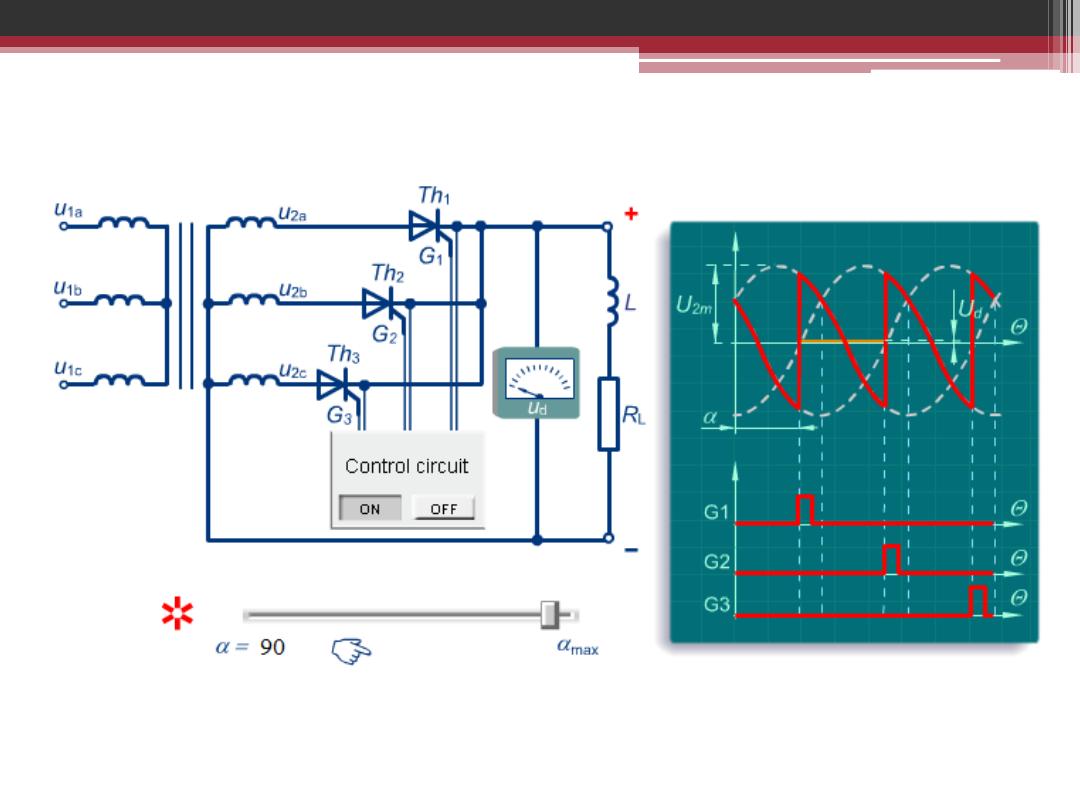
With Inductive Load for α = 90
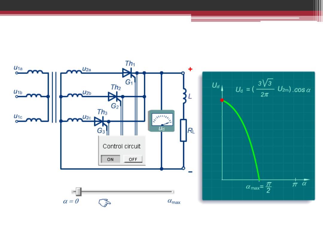
Three Phase Half Controlled Bridge Rectifier
With Inductive Load
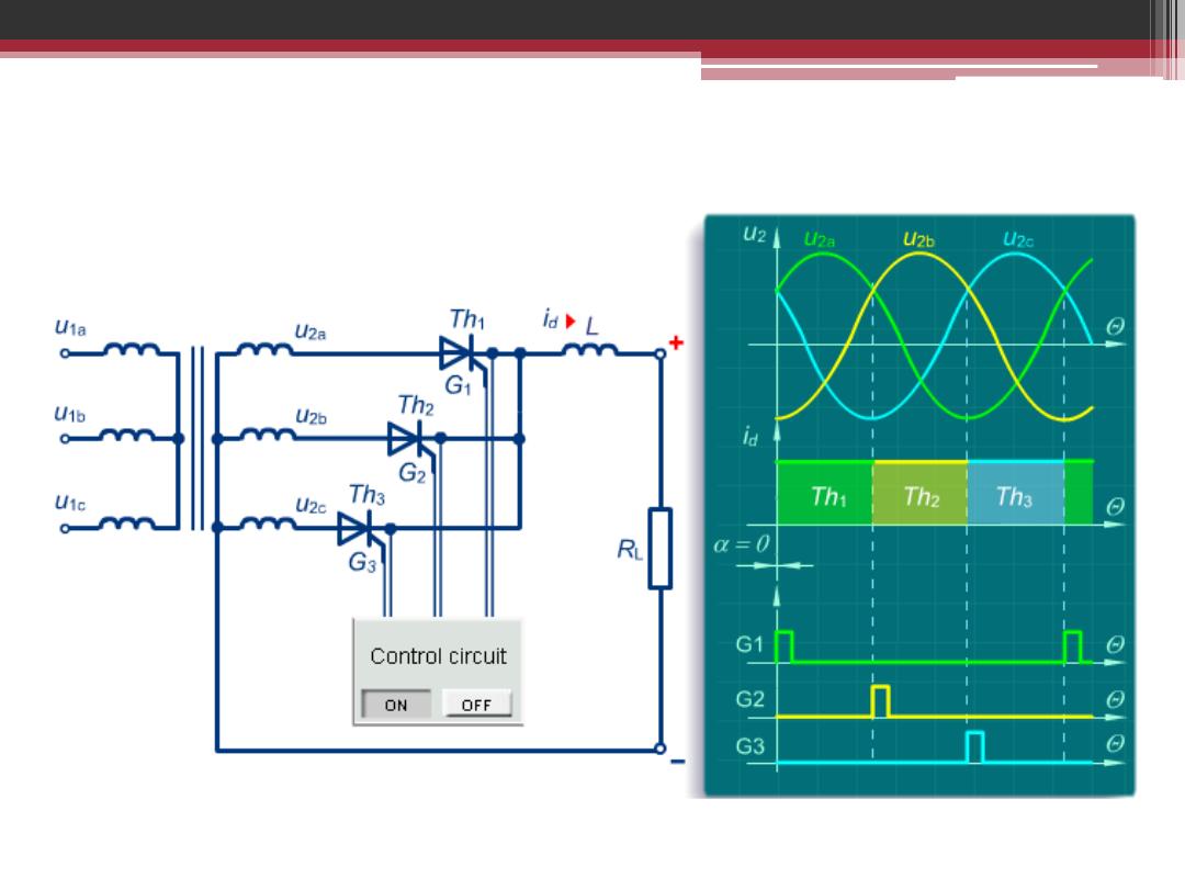
Three Phase Half Controlled Bridge Rectifier
With Inductive Load for α = 0

The End