EQUIVALENT CIRCUIT OF A SINGLE-PHASE TRANSFORMER
Aim:
The determination of electrical equivalent circuit parameters of a single phase power
transformer from open circuit and short circuit tests.
Apparatus:
MATLAB
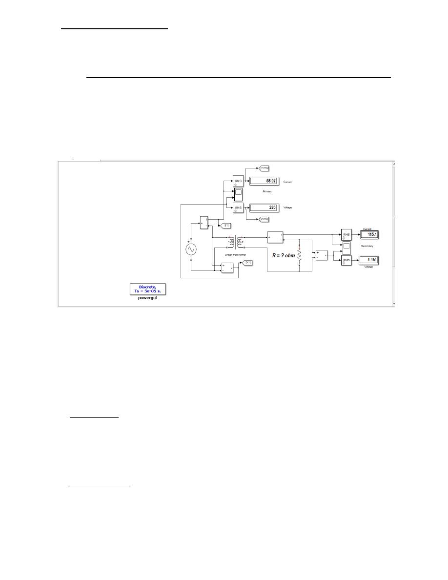
Circuit Diagram:
Procedure:
1. Open File ---> New---> Model.
2. Open Simulink Library and browse the components.
3. Select single phase linear transformer , ratings 1200 VA, 220/110 V, 50 Hz,
4. Connect the components as shown in the above circuit diagram.
5. No-Load Test:
a. Apply voltage to the LV side in steps up to 120% of the rated voltage and for each
case record primary current and power drawn from the source.
b. Increase the applied voltage by 20% and repeat the above step , record all the
readings of the instruments.
6. Short-Circuit Test:
Apply voltage to the HV side in 6 steps up to 120% of the rated current. record all the
readings of the instruments.
Date: 15-11-2016
Electrical Machines Lab
Experiment-No. One
Requirements:
1. Determine the equivalent circuit parameters from the test results.
2. Plot the relation between the voltage, current , power for the input transformer for
open circuit test, and comment on the results.
3. Plot the relation between the voltage, current , power for the input transformer for
short circuit test, and comment on the results.
4. Questions to be answered:
i- Which winding ( LV or HV) should be kept open while conducting OC test?
Justify your answer.
ii- Which winding ( LV or HV) should be kept open while conducting SC test?
Justify your answer.
Theory :
Equivalent Circuit of Transformer
φ mutual
I
1
I
2
V
1
N
1
E
1
E
2
N
2
V
2
LOAD
Fig.
Elementary Transformer
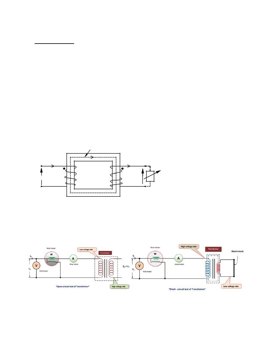
Circuit diagram for open and short circuit
tests
The Open circuit test of the transformer is one of the type test of transformer by which core losses
of the transformer are determined. In this test normal voltage is applied on the low voltage side at
rated frequency and high voltage side is open condition that means there is no load in the
transformer. At that time the reading of wattmeter connected on the low voltage side gives the no
load loss or core losses of the transformer and no load impedance of transformer.
For measuring the Open circuit test, the high voltage winding is left open .A wattmeter, a voltmeter
and an ammeter are connected in the another winding i.e low voltage winding of the transformer. The
connection of Wattmeter, voltmeter and ammeter are shown in the figure. Now normal voltage
applied to the low voltage winding and then recorded the reading of wattmeter, voltmeter & ammeter
which are connected to the low voltage winding.
1. The Wattmeter measures the iron loss (consisting of the hysteresis loss and the eddy current
loss ) of the transformer because the cu- loss is negligibly small in low voltage winding and
nil in the high voltage winding under no load condition.
2. The Ammeter measures the no load current I
0
which is very small ( 2 to 10 % of rated load
current).
3. The voltmeter measures the normal voltage which is applied in the low voltage winding.

Let W is the wattmeter reading and V
1
is the applied voltage and I
0
is the ammeter reading ,Then
W = V
1
I
0
Cos Φ
0
∴ cosΦ
0
= W/V
1
I
0
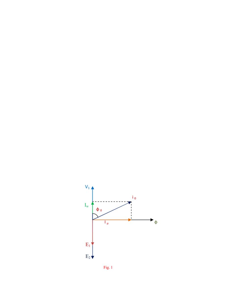
And Iµ = is the magnetizing component of no load current , Iw is the core loss component of no load
current, from the vector diagram of no-load transformer,
Iµ = I
0
sin Φ
0
, I
w
= I
0
cosΦ
0
,
∴ X
0
= V
1
/ Iµ and R
0
= V
1
/I
w
Thus, Z
0
=√(R
0
2
+ X
0
2
)
The admittance is the inverse of impedance. Therefore, Y
0
= 1/Z
0
The conductance G
0
can be calculated as, G
0
=W/V
1
2
Hence the exciting susceptance , B
0
=√(Y
0
2
- G
0
2
)
Why are copper losses neglected in open circuit test ?
Ans: As no load current is very small so the no load copper loss is very small in comparison with the
iron losses so the copper losses are neglected in open circuit test.
Why is kept open high voltage side of transformer during measuring the open circuit test?
Ans: High voltage side is kept open due to suitability of using metering arrangement in the low
voltage side rather than high voltage side
.
The short circuit test of the transformer is the one of type test by which we can measure the full
load cu- loss of the transformer. For testing the short circuit test all meters ( i.e ammeter, wattmeter
and volt meter ) are connected to the high voltage winding and the low voltage winding is short
circuited which is shown in the figure. Now the low voltage is applied at high voltage side and the
applied voltage is slowly increased with the help of variac until the ammeter gives reading equal to
the rated current of the HV side. When the current of HV side reach at rated current of the
transformer, at that time the reading of wattmeter represents the total full-load Cu-losses of the
transformer i.e both primary Cu loss and secondary Cu loss.
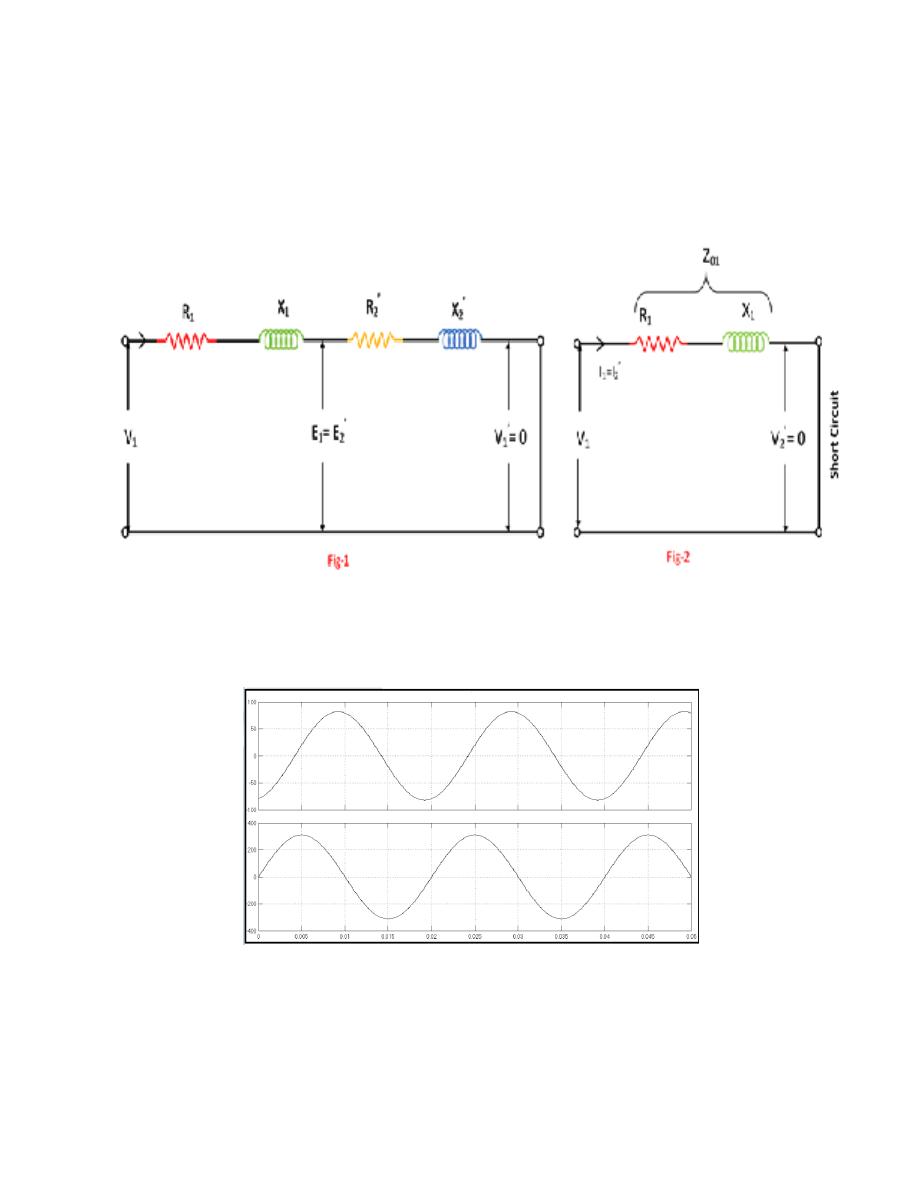
W = Full-load copper loss, V
1
= Applied voltage, I
1
= Rated current, R
01
= Resistance as viewed from
the primary, Z
01
= Total impedance as viewed from the primary, X
01
= Reactance as viewed from the
primary
W=I
1
2
R
01
∴ R
01
=W/I
1
2
Z
01
=V
1
/I
1
X
01
=√(Z
01
2
- R
01
2
)

Result:
Signature of the faculty
6