
1
Electrical Machines Lab
Experiment-No. Two Date: 22-11-2016
LOAD TEST OF A SINGLE-PHASE TRANSFORMER
Aim : To perform load test on single-phase transformer and determine the
followings:
a) Efficiency at different loads, and to plot efficiency verses load curve.
b) Regulation of the transformer and to plot regulation verses load curve.
Theory:
The transformer is a device which transfers energy from one electrical circuit
to another electrical circuit through magnetic field as coupling medium. In this
process, it does not change the frequency of voltage or current. It works on the
basic principle of electromagnetic induction (mutually induced e. m. f.). Being a
static device it has a high efficiency as compared to rotating machine of same
rating as the losses are less.
a- Power input to the transformer ( P
1
) (reading of wattmeter)
Power output of transformer P
2
= V
2
I
2
cos θ
2
watts (cos θ
2
being unity for
resistive load)
Thus, efficiency at a particular load,
b- When primary winding of transformer is energized with source of voltage
V
1
an e.m.f. E
2
is induced across the secondary winding and it is also equal
to secondary terminal voltage V
2
till there is no load across secondary
winding. As soon as load is applied across the secondary winding the
2
terminal voltage is decreased from E
2
to V
2
this phenomenon of changing
the voltage is called “voltage regulation”.
It can be defined voltage regulation in numerical term as “it is change in secondary
terminal voltage from no load to full load with respect to the secondary no load
voltage”.
Thus,
E
2
= No load voltage across secondary.
V
2
= Terminals voltage across secondary at a particular load.
The voltage regulation should be as small as possible. Transformer being highly
inductive device works on lagging power factor unless the load of highly
capacitive nature is connected across the secondary winding to make overall circuit
resistive purely or capacitive in nature.
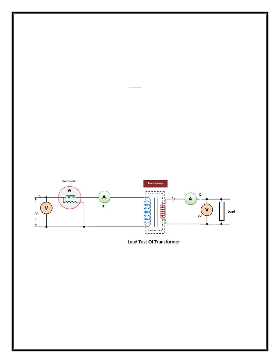
CIRCUIT DIAGRAM:
Figure (1): Circuit Diagram for Single-Phase Transformer
3
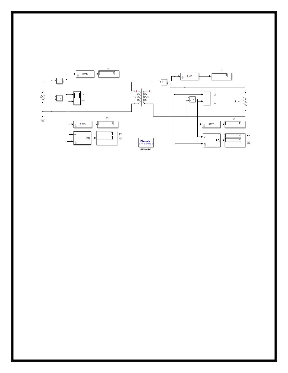
Apparatus: MATLAB
Figure (2): Simulation of Load Test of a Single-Phase Transformer
Procedure:
1- Open File ---> New---> Model.
2- Open Simulink Library and browse the components.
3- Select single phase linear transformer , ratings 1200 VA, 220/110 V, 50 Hz,
4- Connect the components as shown in the above circuit diagram.
5- At the first, ensure that there is no load on the secondary windings of the
transformer to measure no load voltage. Apply the voltage across the
primary side of transformer and record the no load voltage across the
primary & secondary winding.
6- Connect the load, while loading make sure to keep primary voltage at its
rated value, record all the readings of the instruments.
7- Repeat step 6 for various load currents (unity p.f, lag p.f , lead p.f ).
8- Make calculations and fill the table.

4
OBSERVATION TABLE:
Sl.
No.
P
1
(Watts)
E
2
(volts)
V
2
(Volts)
I
2
(Amp)
P
2
=V
2
I
2
cos θ
2
(Watt
)
Efficiency =
(P
2
/ P
1
)* 100
(
)
Requirements:
1. Plot the relation between the efficiency vs. load curve, and comment on
the results.
2. Plot the relation between the voltage regulations vs. load curve, and
comment on the results.