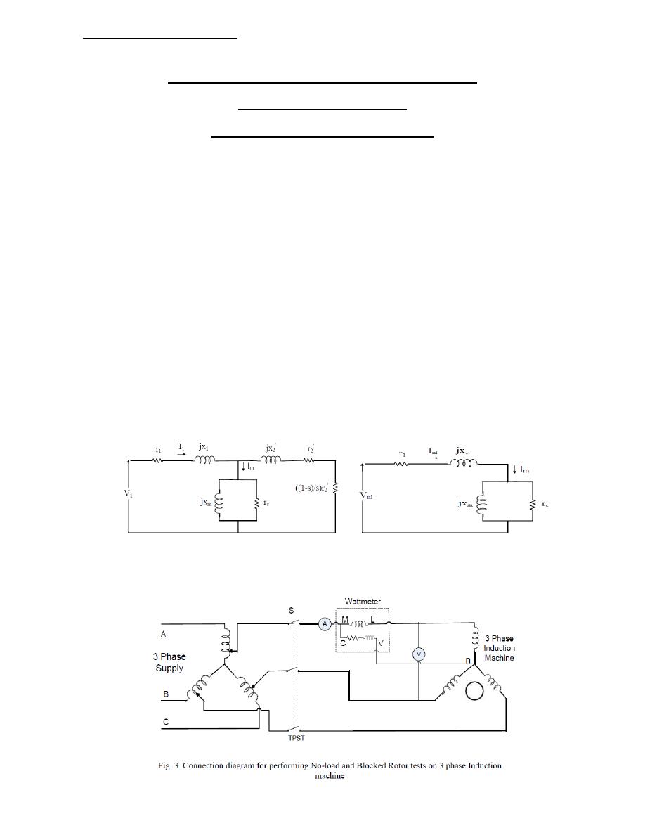
Fig. 1. Equivalent circuit for 3-phase
induction motor per phase
Fig. 2. Approximate equivalent circuit
for no-load test
THREE PHASE INDUCTION MOTOR TESTS
Part A : NO LOAD TEST
Part B: BLOCKED ROTOR TEST
The purposes of the experiment:
1-
To find the equivalent circuit parameters for three-phase induction motor.
2-
To find the iron , copper & mechanical losses for three phase induction motor.
No load test:
THEORY:
The no load test is similar to the open circuit test on a transformer. It is performed to obtain the
magnetizing branch parameters (shunt parameters) in the induction machine equivalent circuit. In
this test, the motor is allowed to run with no-load at the rated voltage of rated frequency across its
terminals. Machine will rotate at almost at synchronous speed, which makes slip nearly equal to
zero. This causes the equivalent rotor impedance to be very large (theoretically infinite
neglecting the frictional and rotational losses). Therefore, the rotor equivalent impedance can be
considered to be an open circuit which reduces the equivalent circuit diagram of the induction
machine (Fig. 1) to the circuit as shown in Fig. 2. Hence, the data obtained from this test will
give information on the stator and the magnetizing branch. The connection circuit diagram of no
load test is shown in Fig. 3. The no load parameters can be found from the voltmeter, ammeter,
and wattmeter readings obtained when the machine is run at no load as shown below:
Electrical Machines Lab
Date: 27-12-2016
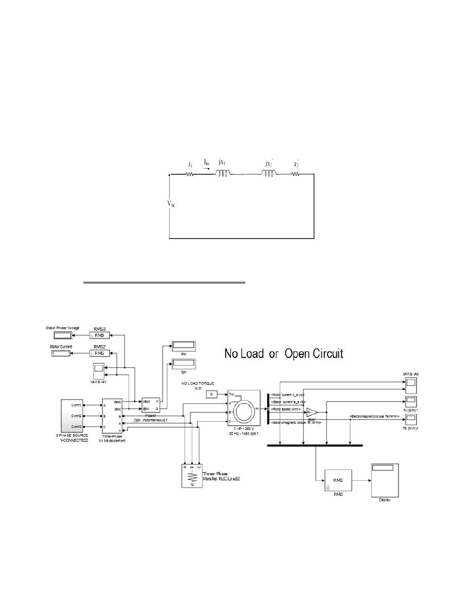
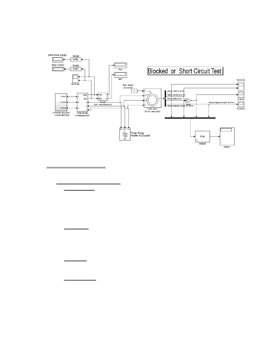
Fig. 4. Equivalent Circuit for Blocked Test
Blocked rotor test:
THEORY: Blocked rotor test is similar to the short circuit test on a transformer. It is
performed to calculate the series parameters of the induction machine i.e., its leakage
impedances. The rotor is blocked to prevent rotation and balanced voltages are applied to
the stator terminals where the rated current is achieved. Under the reduced voltage
condition and rated current, core loss and magnetizing component of the current are quite
small percent of the total current, equivalent circuit reduces to the form shown in Fig. 4.
The model used to simulate this experiment
Parameters of components
1- A synchronous machine block:
a- Configuration:
Preset model: No
Mechanical input: Torque T
m
Rotor type: squirrel-cage
Reference frame: Rotor
Mass units: SI
b- Parameters:
P
n
(VA): 2850
V
n
(Vrms L-L): 380
f(Hz): 50
Another data are remain constant
c- Advanced:
Sample time: -1
3 phase source:
This block consists of three A.C. Voltage sources, as shown below:
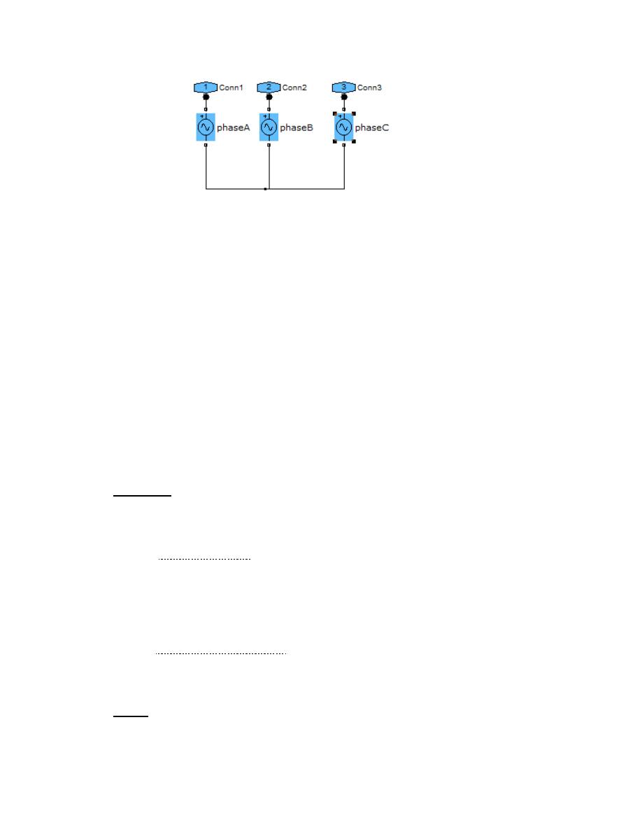
Phase A:
V= K/ (sqrt (3)*sqrt(2))
f= 50Hz
Phase= 0 degree
Sample time= -1
Phase B:
V= K/ (sqrt (3)*sqrt(2))
f= 50Hz
Phase= -120 degree
Sample time= -1
Phase C:
V= K/ (sqrt (3)*sqrt(2))
f= 50Hz
Phase= -240 degree
Sample time= -1
Procedure:
1- Make the model shown above by using matlab Simulink.
2- No load test state: By setting load torque is equal to zero . For the first model &
according to the data shown above record the reading of all meters in the model
for different values of voltage source, as shown below:
Voltage source values:
K= 50,100,150,200,250,300,350,380,400 volt for each phase.
3- A blocked rotor test state: By setting the rotor speed is equal to zero. For second
model change the values of different values of voltage source, as shown below:
K= 5,10,15,20,25,30,35,38,40 volt for each phase
Report
Answer the following:
1- Find the equivalent cct for induction motor at rated values.

2- Find the mechanical, iron and copper losses at rated values.
3- Why the mechanical losses in the blocked rotor test =0.
4- Why the stator current (no load current) in the no load test is low
5- Why the power factor is very low in the no load test.
6- Comment and discuss the results.