
1
Three-Phase Full-Wave Controlled Rectifier
with Different Load Conditions
Aim: To study and analyze the properties and the characteristics of a Three-Phase Full Wave
Controlled Rectifier with both Resistive Load and Highly Inductive Load using (Matlab/
Simulink).
Apparatus: Matlab-Simulink
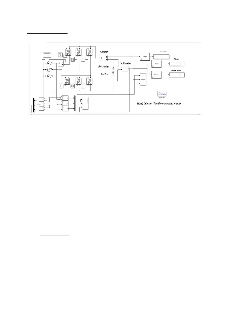
Circuit Diagram:
The Object of the This Experiment
To study and analyze the properties and the characteristics of a Three Phase Full
Wave Controlled Rectifier With resistive and with Highly Inductive Load using
(Matlab/ Simulink).
1- The Mean Value of the Load voltage
V
dc
=
3√3V
π
cos α
The conduction angle of Th1 is 60˚ or (2π/3)
Th
1
firing at α , Th
2
firing at ( α + 60˚ )
Th
3
firing at (α+120˚) , Th
4
firing at (α+180˚)
Th
5
firing at (α+240˚) , Th
6
firing at (α+300˚)
Date: 13-12-2016
Power Electronics Lab
2
The Procedures
Procedure and Requirements:
1- Open File ---> New---> Model.
2- Open Simulink Library and browse the components.
3- Connect the components as per circuit diagram.
4- Set the input supply voltage (Vrms = 380 volt & 50 Hz), the load is (R=25 Ω ) and
trigger angle (α= choose suitable value to obtain certain value of
V
dc
).
5- Simulate the circuit using
Matlab-Simulink
.
6- At steady state condition, determine the mean and rms values of the output voltage
and current using
Matlab-Simulink
.
7- Repeat Part 6, by inserting L ≈ 1.5 H in series with R= 10Ω.
8- For parts 6 or 7, change the value of (α) from (0 , 30˚, 60˚, ……) step (30 ̊ ), then record
the corresponding mean values of the output voltage (V
dc
), then plot the relation between
(V
dc
against α ).
9- Draw the spectrums for load current for both types of load at α= 60˚.
10- Plot the instantaneous waveforms for: load voltage, load current, supply voltage and
supply current , Thyristor voltage and Thyristor Current, at α= 60˚
11- Comment on the results by comparing between theoretical and simulation.
The Discussion
1- Determine the mean value of the output voltage theoretically and compare it with the
simulink results.
2- Determine the value of the ripple factor (RF) of the circuit.
3- Depending on your results determine the value of the efficiency of the rectifier.
4- Depending on your results determine the value of the input power factor (PF).
5- Depending on your results draw the relation between (V
dc
) Against (α).