1
Electrical Machines Lab
Experiment-No.
ROTOR RESISTANCE SPEED CONTROL OF WOUND ROTOR
INDUCTION MOTOR
AIM: To vary the speed of the wound rotor induction motor using rotor rheostat
control.
Theory
The main advantage of wound rotor induction motor over the squirrel cage motor is
that it offers one more degree of freedom to the Engineers for starting & speed
control. Wound rotor Induction Motor is used where the load requirements are high
starting toque & variable speed, or where the motor is to be started under heavy
load. Typical applications of these motors are crane & hoist control. Resister
controllers in the rotor circuit are used to achieve smooth start & speed control.
Resent investigations have shown that certain desired torque speed characteristics
can be achieved by insertion of relatively simple passive frequency sensitive
networks. Careful selection of network parameters leads to highly reduced starting
current & & improved torque/ current ratio. To understand the industrial systems
incorporating the wound rotor Induction Motors it is therefore necessary to study
the effect of rotor impedance on the performance of Induction Motors.
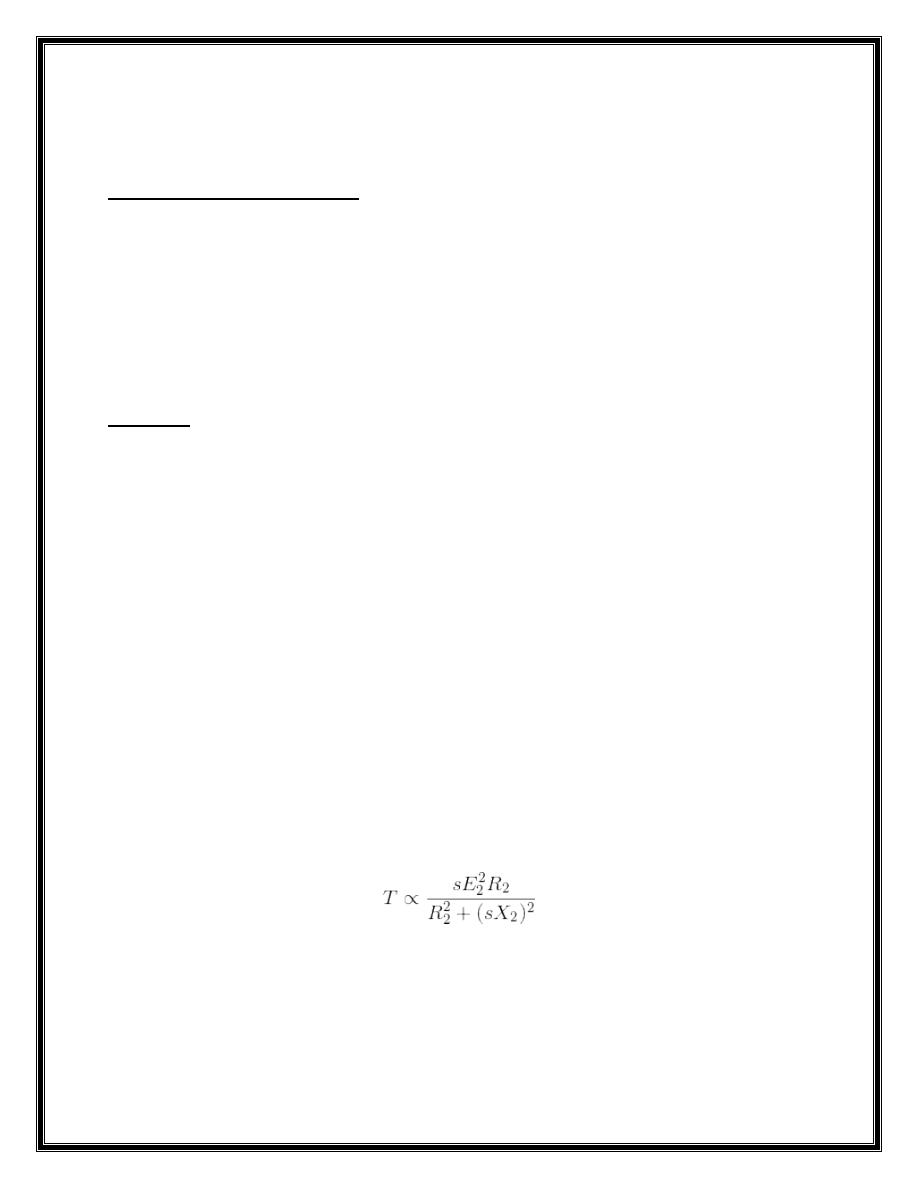
In this method of speed control of three phase induction motor external resistance
are added on rotor side. The equation of torque for three phase induction motor is
The three phase induction motor operates in low slip region. In low slip region
term (sX)2 becomes very small as compared to R2. So, it can be neglected. And
also E2 is constant. So the equation of torque after simplification becomes,
2
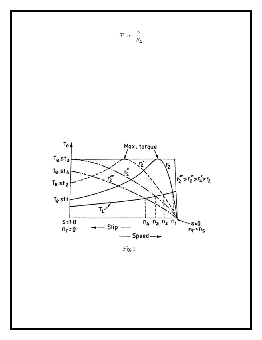
Now if we increase rotor resistance, R2 torque decreases but to supply the same
load torque must remain constant. So, we increase slip, which will further results in
decrease in rotor speed. Thus by adding additional resistance in rotor circuit we
can decrease the speed of three phase induction motor. The main advantage of this
method is that with addition of external resistance starting torque increases but this
method of speed control of three phase induction motor also suffers from some
disadvantages:
1. The speed above the normal value is not possible.
2. Large speed change requires large value of resistance and if such large value of
resistance is added in the circuit it will cause large copper loss and hence
reduction in efficiency.
3. Presence of resistance causes more losses.
4. This method cannot be used for squirrel cage induction motor.
From the
figure 1 it is clear how does the speed vary with the change of rotor
resistance.
3
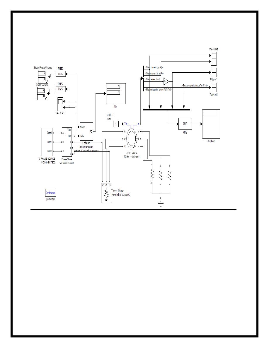
The model used to simulate this experiment
Figure 2 simulation the wound rotor induction motor
Parameters of components
1- A synchronous machine block:
a- Configuration:
Preset model: No
Mechanical input: Torque Tm
Rotor type: wound rotor
Reference frame: Rotor
Mass units: SI
b- Parameters:
4
Pn (VA): 2850
Vn (Vrms L-L): 380
f(Hz): 50
Another data are remain constant
c- Advanced:
Sample time: -1
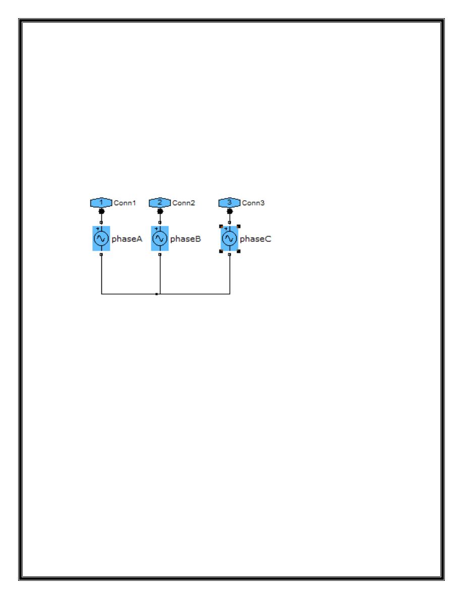
3 phase source:
This block consists of three A.C. Voltage sources, as shown below:
1- Phase A:
2- V= K/ (sqrt (3)*sqrt(2))
3- f= 50Hz
4- Phase= 0 degree
5- Sample time= -1
6- Phase B:
7- V= K/ (sqrt (3)*sqrt(2))
8- f= 50Hz
9- Phase= -120 degree
10-
Sample time= -1
11-
Phase C:
12-
V= K/ (sqrt (3)*sqrt(2))
13-
f= 50Hz
14-
Phase= -240 degree
15-
Sample time= -1

5
PROCEDURE:
1 - Open File ---> New---> Model.
2 - Open Simulink Library and browse the components.
3 - Connect the components as shown in the above circuit, figure 2.
4 - Simulate the circuit to start motor with rotor resistance starter.
5 – observe the waveforms of speed, torque, stator current and rotor current.
6 - The rotor resistance is varied and corresponding values of speed, voltage ,
currents and torque are noted down.
Rotor
Resistance
Voltage
(V)
Stator
current (A)
Rotor
current(A)
Speed
(rpm)
Torque
(N.m)
50
40
30
20
10
Report
1- Plot the relation between the rotor resistances with speed.
2- As you added resistance externally to the rotor circuit, what happened to
rotor speed? Why?
3- As rotor speed decreased, what happened to the torque output of the motor?
Why?
4- As rotor speed decreased, what happened to the current being induced into
the rotor circuit?