0
ﺎﺋﯿﺔــﺑﺮﮭﻜﻟا ﺔﺳﺪﻨﮭﻟا ﻢﺴﻗ ﻞــــﺻﻮﻤﻟا ﺔﻌﻣﺎﺟ
ﺎﻻتــﺼﺗﻻاو ﻚـــﯿﻧوﺮﺘﻜﻟﻻا عﺮـــــــــــــــﻓ
ﺎروديــﺒﻟا ﺪﻤﺤﻣ ﺪﯾﺆﻣ ناوﺮﻣ ﺐﻟﺎﻄﻟا داﺪﻋا
ﻛﻠﯿ
ـــــ
ﺔ اﻟﮭﻨﺪﺳ
ـــــــــــــــــــــــــ
ﺔ
اﻋﺪاد اﻟﻄﺎﻟﺐ ﻣﺮوان ﻣﺆﯾﺪ ﻣﺤﻤﺪ ﺳﻌﯿﺪ اﻟﺒﺎرودي
ﺎءـــــــــــــــــــــــــــــــــــﺑﺮﮭﻜﻟا ﻢــــــﺴﻗ
ﻞـــــــــــــــﺻﻮﻤﻟا ﺔــﻌﻣﺎﺟ
ﻻ
ﺎـﻧﻮﺴﻨﺗ
ﺢــﻟﺎﺻ ﻦﻣ
ﻢـــــــﻜﺋﺎﻋد

1
ﺎﺋﯿﺔــﺑﺮﮭﻜﻟا ﺔﺳﺪﻨﮭﻟا ﻢﺴﻗ ﻞــــﺻﻮﻤﻟا ﺔﻌﻣﺎﺟ
ﺎﻻتــﺼﺗﻻاو ﻚـــﯿﻧوﺮﺘﻜﻟﻻا عﺮـــــــــــــــﻓ
ﺎروديــﺒﻟا ﺪﻤﺤﻣ ﺪﯾﺆﻣ ناوﺮﻣ ﺐﻟﺎﻄﻟا داﺪﻋا
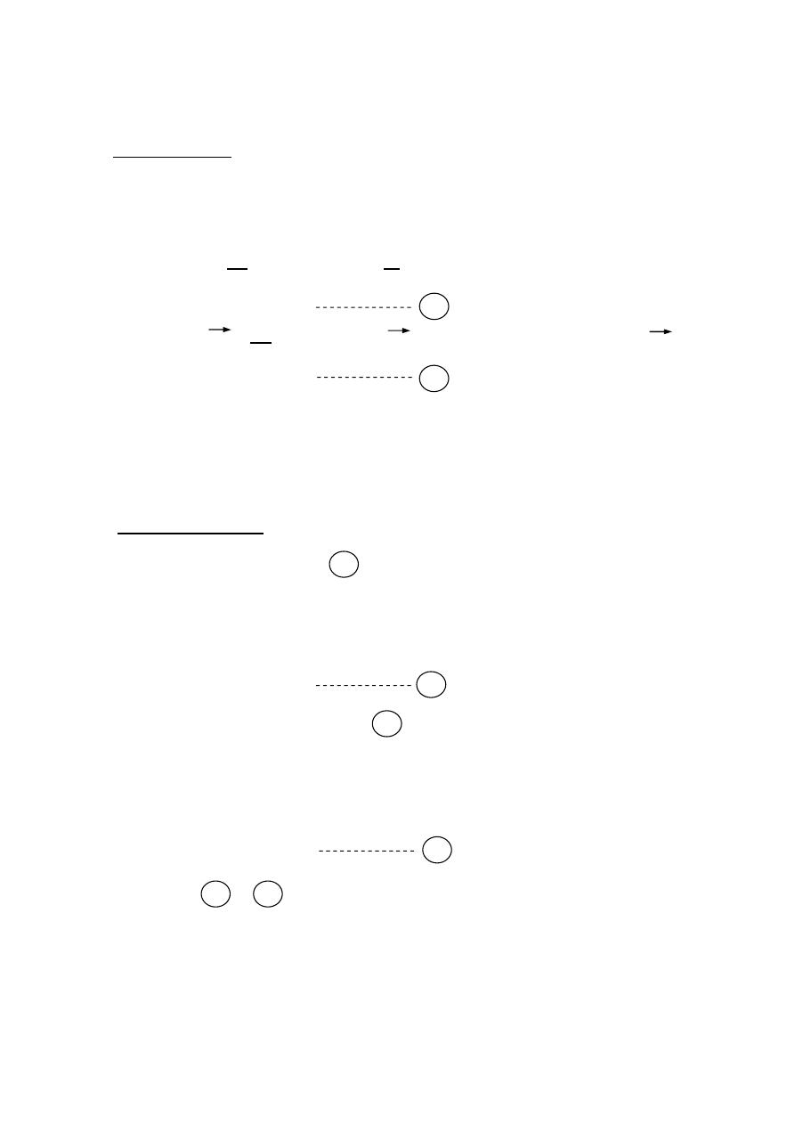
MAXWELL'S EQUATIONS
The four field quantities of interest are:
1- Electric field intensity E(
V/m ).
2- Magnetic field intensity H(
A/m ).
3- Electric flux density D(
C/m ).
4- Magnetic flux density B(
wb/m ).
The fields are related by Maxwell's equations as follows:
∇ × E⃗ = −
⃗
∇ × H⃗ = ⃗ +
⃗
where
= E⃗
∇ . D⃗ =
where
D⃗ = ε E⃗ ⟹ D⃗ = ε ε E⃗
∇ . B⃗ = 0
where
B⃗ = H⃗ ⟹ B⃗ =
H⃗
:
conductivity mho/m (s/m)
ε =
36
×
10
−9
:
resistivity ohm .s
=
4
×
10
−7
Ex
:- Given an electric field ⃗
= A
cosω
t −
Z
c
y⃗
determine the time
dependent magnetic field intensity in free space (A&c constant).
The solution:-
∇ × E⃗ = −
⃗
⃗
⃗
⃗
= −
⃗
−
⃗
−
−
⃗ +
−
⃗ = −
⃗
−
⃗ = −
⃗
⟹
A
cosω
t−
Z
c
=
= 1
ω
sinω
t −
=
= ∫
ω
sinω
t −
= −
ω
ω
cosω
t −
⃗ = −
cosω
t −
⃗ + 0 ⃗ + 0 ⃗
J
J

2
ﺎﺋﯿﺔــﺑﺮﮭﻜﻟا ﺔﺳﺪﻨﮭﻟا ﻢﺴﻗ ﻞــــﺻﻮﻤﻟا ﺔﻌﻣﺎﺟ
ﺎﻻتــﺼﺗﻻاو ﻚـــﯿﻧوﺮﺘﻜﻟﻻا عﺮـــــــــــــــﻓ
ﺎروديــﺒﻟا ﺪﻤﺤﻣ ﺪﯾﺆﻣ ناوﺮﻣ ﺐﻟﺎﻄﻟا داﺪﻋا
Ex:-
Given a magnetic field in free space where there is neither charge non
current density .
⃗
=
sin(ω −
) ⃗ +
cos (
−
) ⃗
where a,n and w are constant . determine the electric field
E⃗
The solution:-
∇ × E⃗ = −
⃗
⃗
⃗
⃗
= −
⃗
⃗
=
cos
(
ω −
) ⃗
−
(
−
)
⃗
−
⃗
−
−
⃗ = −
cos
(
ω −
) ⃗
−
(
−
)
⃗
−
⃗ = −
−
(
−
)
⃗
⃗
=
−
(
−
) ⃗
=
−
(
−
)
=
− ∫
(
−
)
=
−
∫
(
−
)
=
(
−
)
⃗ =
0
⃗
+ 0
⃗
+
(
−
) ⃗
Ex
:- Given
B⃗ = 10
1 −
2
4
sin 3 × 10 t ⃗ In cylindrical coordinate system
find ⃗.
The solution:-
∇ × ⃗ = −
⃗
= −3 1 −
3 × 10
−
= −3 1 −
2
4
3 × 10
8
= −
3 1
−
2
4
3 × 10
8
⟹
= −3
1 −
4
3 × 10
8
= −
3
3 × 10
8
∫
−
4
⟹
= −
3
2
−
16
3 × 10
8
⃗
= 0 ⃗ + −
3
−
3
3 × 10
8
⃗ + 0 ⃗
3
ﺎﺋﯿﺔــﺑﺮﮭﻜﻟا ﺔﺳﺪﻨﮭﻟا ﻢﺴﻗ ﻞــــﺻﻮﻤﻟا ﺔﻌﻣﺎﺟ
ﺎﻻتــﺼﺗﻻاو ﻚـــﯿﻧوﺮﺘﻜﻟﻻا عﺮـــــــــــــــﻓ
ﺎروديــﺒﻟا ﺪﻤﺤﻣ ﺪﯾﺆﻣ ناوﺮﻣ ﺐﻟﺎﻄﻟا داﺪﻋا
Solution of Maxwell's Equation For Free Space Condition
s:
Assumption
1-we will deal with sinusoidal time varying field
.
2-The medium is assumed to be homogeneous isotropic and source free
∇ × ⃗ = −
⃗
where
=
∇ × ⃗ = −
⃗
∇ × H⃗ = ⃗ +
⃗
where
= E⃗ = 0
free space
∴ = 0
∇ × H⃗ =
⃗
∇ . D⃗ =
where
=
0
free space
∇ . D⃗ = 0
∇ . B⃗ = 0
Wave Equations
Take Curl of both sides of
∇ × ∇ × ⃗ = −
∇ × ⃗
∇ ∇. ⃗ − ∇ ⃗ = −
⃗
∇ ⃗ = −
⃗
Also Take Curl of both sides of
∇ × ∇ × ⃗ =
∇ × ⃗
∇ ∇. ⃗ − ∇ ⃗ =
−
⃗
∇ ⃗ = −
⃗
Equations & are called wave equation.
1
J
J
J
2
1
a
b
2
b
a
4
ﺎﺋﯿﺔــﺑﺮﮭﻜﻟا ﺔﺳﺪﻨﮭﻟا ﻢﺴﻗ ﻞــــﺻﻮﻤﻟا ﺔﻌﻣﺎﺟ
ﺎﻻتــﺼﺗﻻاو ﻚـــﯿﻧوﺮﺘﻜﻟﻻا عﺮـــــــــــــــﻓ
ﺎروديــﺒﻟا ﺪﻤﺤﻣ ﺪﯾﺆﻣ ناوﺮﻣ ﺐﻟﺎﻄﻟا داﺪﻋا
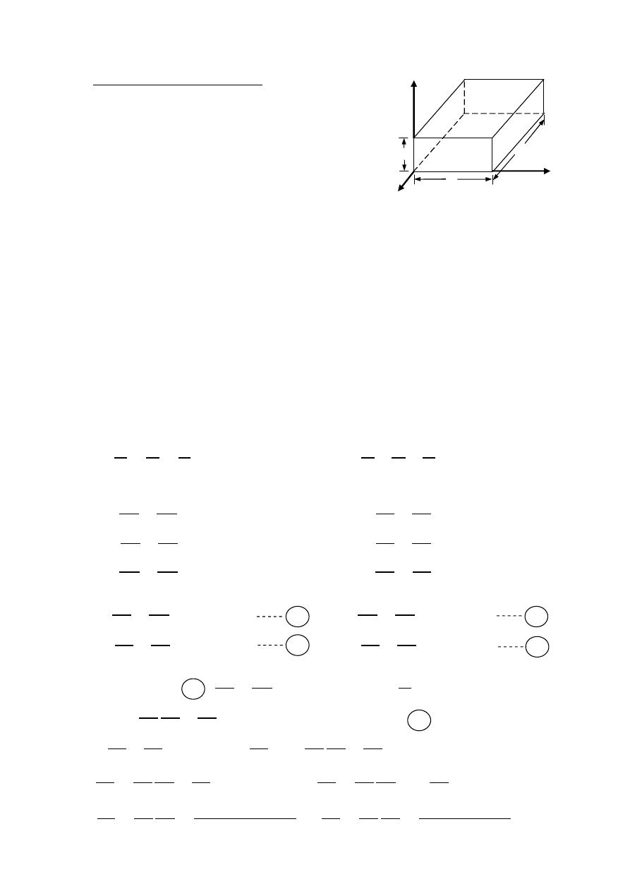
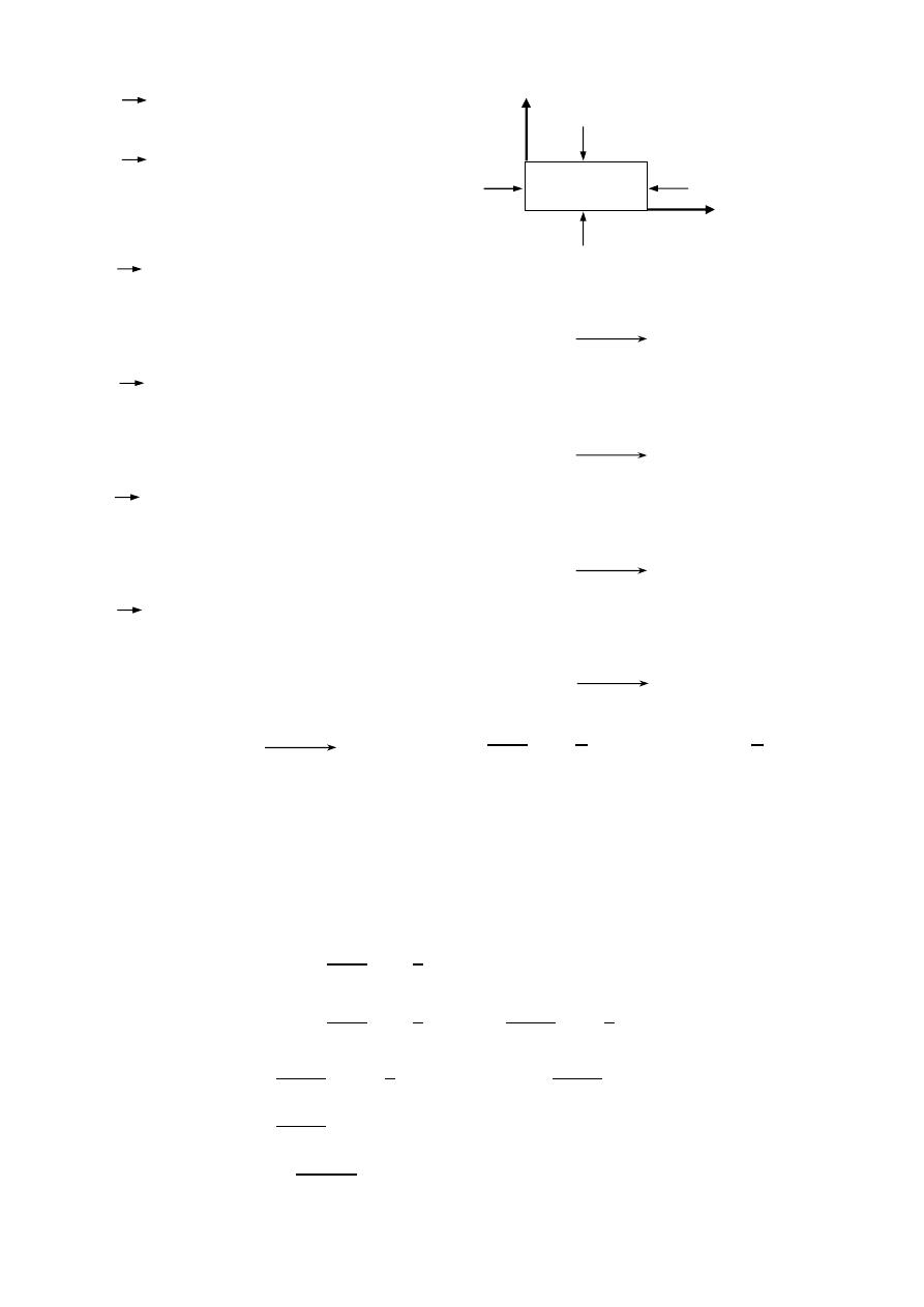
Rectangular Waveguides
Assumptions:
1-perfect conducting for the walls
of the guide (
= ∞).
2-lossless region within the guide (
= 0).
3-deal with sinusoidal time varying field
.
4-the variation in Z-direction may be expressed as
.
where
is the complex propagation constant.
=
+
: attenuation constant neper/m
: phase constant rad/m
,
,
&
are called transverse components.
&
are called lonyitudinal components.
∇ × H⃗ =
⃗ ∇ × ⃗ = −
⃗
⃗
⃗
⃗
=
⃗
⃗
⃗
⃗
= −
⃗
−
=
−
= −
−
−
=
−
−
= −
−
=
−
= −
−
=
−
= −
−
=
−
= −
from equation
−
=
where
= − , ℎ =
+
=
1
+
by substitution of equation
−
=
⟹
+
1
+
=
+
+
2
=
⟹
+
=
−
2
+
+
=
−
2
2 2
⟹
+
=
−
2
2
y
x
z
b
a
a
b
c
d
b
a
d
5
ﺎﺋﯿﺔــﺑﺮﮭﻜﻟا ﺔﺳﺪﻨﮭﻟا ﻢﺴﻗ ﻞــــﺻﻮﻤﻟا ﺔﻌﻣﺎﺟ
ﺎﻻتــﺼﺗﻻاو ﻚـــﯿﻧوﺮﺘﻜﻟﻻا عﺮـــــــــــــــﻓ
ﺎروديــﺒﻟا ﺪﻤﺤﻣ ﺪﯾﺆﻣ ناوﺮﻣ ﺐﻟﺎﻄﻟا داﺪﻋا
+
=
2
2
⟹ −
−
=
ℎ
2
= −
ℎ
2
−
ℎ
2
also from equation
−
=
⟹
1
−
1
=
=
1
+
by substitution of equation
−
=
⟹
+
1
+
=
+
+
2
=
⟹
+
= −
2
+
+
=
−
2
2 2
⟹
+
=
−
2
2
+
=
−
2
2
⟹ −
−
=
ℎ
2
= −
ℎ
2
−
ℎ
2
from equation
−
= −
⟹
= −
1
−
= −
1
−
by substitution of equation
−
= −
⟹
+
−
1
−
= −
−
−
2
= −
⟹ −
+
+
2
=
−
+
= −
2
+
⟹ −
+
=
−
2
2 2
−
+
=
−
2
2
⟹ −
+
=
−
2
2
−
=
2
2
⟹
−
=
ℎ
2
= −
ℎ
2
+
ℎ
2
Also from equation
−
= −
⟹
= −
1
−
= −
1
−
by substitution of equation
−
= −
⟹
+
−
1
−
= −
−
−
2
= −
⟹ −
+
= −
2
+
−
+
=
−
2
2
⟹
−
=
ℎ
2
= −
ℎ
2
+
ℎ
2
b
a
1
2
c
d
3
d
c
4

6
ﺎﺋﯿﺔــﺑﺮﮭﻜﻟا ﺔﺳﺪﻨﮭﻟا ﻢﺴﻗ ﻞــــﺻﻮﻤﻟا ﺔﻌﻣﺎﺟ
ﺎﻻتــﺼﺗﻻاو ﻚـــﯿﻧوﺮﺘﻜﻟﻻا عﺮـــــــــــــــﻓ
ﺎروديــﺒﻟا ﺪﻤﺤﻣ ﺪﯾﺆﻣ ناوﺮﻣ ﺐﻟﺎﻄﻟا داﺪﻋا
we obtained on transverse components equations.
= −
ℎ
2
−
ℎ
2
= −
ℎ
2
+
ℎ
2
= −
ℎ
2
+
ℎ
2
= −
ℎ
2
−
ℎ
2
(TM)
Transverse Modes
If
E & H
are both
zero , all the fields within the guide will vanish .
It is convenient to divide the possible field configuration within the guide
into two sets :
1- transverse magnetic (TM) waves for which
= 0
,
≠
0
.
2- transverse electric (TE) waves for which
≠
0
,
= 0
.
1- transverse magnetic (TM) waves for which
= 0
,
≠
0
.
∇ ⃗ = −
⃗
∇ ⃗ = −
+
+
+
= 0
+
+
+
= 0
+
+ (
+
)
= 0
( , , ) =
( , )
Let
= XY
Where
X is a function of x only & Y is a function of y only
+
+ (
+
)XY = 0
Y
+ X
+ ℎ XY = 0 ÷ XY
+
+ ℎ = 0
+ ℎ =
&
= −
The complement of the solution is not required in the subject of radiation & propagation.
1
2
3
4

7
ﺎﺋﯿﺔــﺑﺮﮭﻜﻟا ﺔﺳﺪﻨﮭﻟا ﻢﺴﻗ ﻞــــﺻﻮﻤﻟا ﺔﻌﻣﺎﺟ
ﺎﻻتــﺼﺗﻻاو ﻚـــﯿﻧوﺮﺘﻜﻟﻻا عﺮـــــــــــــــﻓ
ﺎروديــﺒﻟا ﺪﻤﺤﻣ ﺪﯾﺆﻣ ناوﺮﻣ ﺐﻟﺎﻄﻟا داﺪﻋا
= (C cos Bx + C sinBx)(C cos Ay + C sinAy)
=
C C cos Bx cosAy
+
C C cos Bx sinAy
+
C C sinBx cos Ay
+
C C sinBx sinAy
Boundary condition:
=
= 0 = 0
=
= 0 = 0
=
= 0 =
=
= 0 =
∎
= 0 = 0
C C cos Ay + C C sinAy = 0
∴ C = 0
∴
= C C sinBx cos Ay
+
C C sinBx sinAy
∎
= 0 y = 0
C C sinBx = 0
∴ C = 0
= C C sinBx sinAy let C C = C
∴
= C sinBx sinAy
∎
= 0 =
∴ C sin (B ) sin(Ay) = 0
sin (B ) = 0 ⟹ B = 0 , , 2 ⟹
=
where
= 0, 1 , 2 , 3 , ….
∴
=
∎
= 0 =
C sin
sin(Ab) = 0
sin(Ab) = 0 ⟹ Ab = 0 , , 2 ,…. ⟹ Ab =
where = 0 ,1 , 2 , 3 , ....
∴
=
= C sin
sin
y
= C sin
sin
y
=
+
⟹ = 0 ⟹ =
8
ﺎﺋﯿﺔــﺑﺮﮭﻜﻟا ﺔﺳﺪﻨﮭﻟا ﻢﺴﻗ ﻞــــﺻﻮﻤﻟا ﺔﻌﻣﺎﺟ
ﺎﻻتــﺼﺗﻻاو ﻚـــﯿﻧوﺮﺘﻜﻟﻻا عﺮـــــــــــــــﻓ
ﺎروديــﺒﻟا ﺪﻤﺤﻣ ﺪﯾﺆﻣ ناوﺮﻣ ﺐﻟﺎﻄﻟا داﺪﻋا
The transverse component become
=
cos
(
Bx
)
sin
(Ay)
=
sin
(
Bx
)
cos(Ay)
=
sin
(
Bx
)
cos(
Ay
)
=
cos
(
Bx
)
sin(Ay)
Note : since
=
+
& for propagation
=
only where
= 0
∴ replaced by
.
Ex:-
starting with expression
= (C cos Bx + C sinBx)(C cos Ay + C sinAy)
Prove that the final expression of
for transverse magnetic waves in
Rectangular wave guide is given by
= C sinBx
sinAy.
2- transverse electric (TE) waves for which
≠
0
,
= 0
.
∇ ⃗ = −
⃗
∇ ⃗ = −
+
+
+
= 0
+
+
+
= 0
+
+ (
+
)
= 0
( , , ) =
( , )
Let
= XY
Where
X is a function of x only & Y is a function of y only
+
+ (
+
)XY = 0
Y
2
X
2
+ X
2
Y
2
+ ℎ XY = 0 ÷ XY
2
X
2
+
2
Y
2
+ ℎ = 0
2
X
2
+ ℎ =
&
2
Y
2
= −
The complement of the solution is not required in the subject of radiation & propagation.

9
ﺎﺋﯿﺔــﺑﺮﮭﻜﻟا ﺔﺳﺪﻨﮭﻟا ﻢﺴﻗ ﻞــــﺻﻮﻤﻟا ﺔﻌﻣﺎﺟ
ﺎﻻتــﺼﺗﻻاو ﻚـــﯿﻧوﺮﺘﻜﻟﻻا عﺮـــــــــــــــﻓ
ﺎروديــﺒﻟا ﺪﻤﺤﻣ ﺪﯾﺆﻣ ناوﺮﻣ ﺐﻟﺎﻄﻟا داﺪﻋا
H = (C cos Bx + C sinBx)(C cos Ay + C sinAy)
H
=
C C cos Bx cosAy
+
C C cos Bx sinAy
+
C C
sinBx
cos Ay
+
C C sinBx sinAy
= −
ℎ
2
−
ℎ
2
⟹
=
−
ℎ
2
= −
ℎ
2
+
ℎ
2
⟹
=
ℎ
2
Boundary condition
∎
=
= 0 & = 0
=
ℎ
2
⟹ 0 =
ℎ
2
⟹
=
0
=
−C
1
C
3
B sin Bx cosAy
−
C
1
C
4
Bsin Bx sinAy
+
C
2
C
3
BcosBx
cos Ay
+
C
2
C
4
Bcos
Bx sinAy
∎
= 0
&
=
0
0
= C
2
C
3
B cos Ay
+
C
2
C
4
B sinAy
∴ C = 0
H
=
C C cos Bx cosAy
+
C C cos Bx sinAy
∎
=
= 0 & = 0
=
−
ℎ
2
⟹ 0 =
−
ℎ
2
⟹
=
0
= −C
1
C
3
A cos Bx sinAy
+
C
1
C
4
A cos Bx cosAy
∎
= 0
&
=
0
0
= C
1
C
4
A cos Bx
C ≠ 0 , C = 0
H
=
C C cos Bx cosAy
let
C C = C
H
=
C cos Bx cosAy
Ex:-
starting with expression
H = (C cos Bx + C sinBx)(C cos Ay + C sinAy)
Prove that the final expression of
H for transverse magnetic waves in
Rectangular wave guide is given by
H = C cosBx
cosAy.

10
ﺎﺋﯿﺔــﺑﺮﮭﻜﻟا ﺔﺳﺪﻨﮭﻟا ﻢﺴﻗ ﻞــــﺻﻮﻤﻟا ﺔﻌﻣﺎﺟ
ﺎﻻتــﺼﺗﻻاو ﻚـــﯿﻧوﺮﺘﻜﻟﻻا عﺮـــــــــــــــﻓ
ﺎروديــﺒﻟا ﺪﻤﺤﻣ ﺪﯾﺆﻣ ناوﺮﻣ ﺐﻟﺎﻄﻟا داﺪﻋا
Propagation constant
=
+
h = A + B & h =
+ ω
A + B =
+ ω
=
A + B − ω
where A =
&
B =
There are three cases :
F = Fc where Fc : cutoff frequency
= 0 ⟹ no propagation
0 =
A + B − w
0 =
+
− ω
Fc
=
1
2
+
cutoff frequency
Fc
=
C
2
in case n = 0
Fc
=
C
2
in case m = 0
=
C
Fc
=
2
2
+
2
cutoff wave length
= 2 in case n = 0
F < Fc
= 2 in case m = 0
is real
⟹ no propagation
= only = 0 ∴ no propagation
=
=
+
− w
F > Fc There is propagation
=
only
= 0
=
=
ω
−
−
or
=
ω
−
−
=
=
C
1−
Fc
F
2
=
F
=
2
: is the wave length within the guide .
a
b
c
11
ﺎﺋﯿﺔــﺑﺮﮭﻜﻟا ﺔﺳﺪﻨﮭﻟا ﻢﺴﻗ ﻞــــﺻﻮﻤﻟا ﺔﻌﻣﺎﺟ
ﺎﻻتــﺼﺗﻻاو ﻚـــﯿﻧوﺮﺘﻜﻟﻻا عﺮـــــــــــــــﻓ
ﺎروديــﺒﻟا ﺪﻤﺤﻣ ﺪﯾﺆﻣ ناوﺮﻣ ﺐﻟﺎﻄﻟا داﺪﻋا
Ex
:- Prove that
=
C
1−
Fc
F
2
The solution:-
=
=
2
ω
2
−
2
−
2
=
2
ω
2
−
2
+
2
Fc
=
1
2
+
2 Fc √ =
+
square both sides
(
2 )
=
+
Equation in
=
2
ω
2
−
(
2
)
2
2
=
2
(
2
)
2
2
−
(
2
)
2
2
=
2
(
2
)
2
2
−
2
=
2
2
2
−
2
=
2
−
2
÷
=
2
2
−
2
2
⟹
=
1−
2
2
⟹
=
1−
2
Ex
:- Prove that
=
+
The solution:-
=
F
=
1−
2
F
=
F
1−
2
=
1−
2
where
=
=
1−
2
⟹
=
2
1−
2
⟹
=
2
1−
2
2
2
2
=
2
1−
2
2
÷
2
2
=
2
2
1
2
−
2
2 2
⟹
=
1
1
2
−
1
2
⟹
1
2
−
1
2
=
1
2
⟹
1
2
=
1
2
+
1
2
1
2
2
1
12
ﺎﺋﯿﺔــﺑﺮﮭﻜﻟا ﺔﺳﺪﻨﮭﻟا ﻢﺴﻗ ﻞــــﺻﻮﻤﻟا ﺔﻌﻣﺎﺟ
ﺎﻻتــﺼﺗﻻاو ﻚـــﯿﻧوﺮﺘﻜﻟﻻا عﺮـــــــــــــــﻓ
ﺎروديــﺒﻟا ﺪﻤﺤﻣ ﺪﯾﺆﻣ ناوﺮﻣ ﺐﻟﺎﻄﻟا داﺪﻋا
Notes:-
For (TE) it is possible to make either m or n (but not both) equal to zero.
=
c
cos
(
B
)
cos
(
Ay
)
or
=
c
cos
(
B
)
cos
(
Ay
)
−
=
ℎ
2
sin
(
B
)
cos
(
Ay
)
or
=
ℎ
2
sin
(
B
)
cos
(
Ay
)
−
=
ℎ
2
cos(B ) sin(Ay) or
=
ℎ
2
cos(B ) sin(Ay)
−
=
ℎ
2
cos
(
B
)
sin
(
Ay
)
or
=
ℎ
2
cos
(
B
)
sin
(
Ay
)
−
=
−
ℎ
2
sin
(
B
)
cos
(
Ay
)
or
=
−
ℎ
2
sin
(
B
)
cos
(
Ay
)
−
For (TM) it is not possible to make m or n equal to zero.
= C sin
(
B
)
sin
(
Ay
)
or
= C sin
(
B
)
sin
(
Ay
)
−
=
ℎ
2
cos
(
B
)
sin(Ay) or
=
ℎ
2
cos
(
B
)
sin(Ay)
−
=
ℎ
2
sin
(
B
)
cos(Ay) or
=
ℎ
2
sin
(
B
)
cos(Ay)
−
=
ℎ
2
sin
(
B
)
cos(Ay) or
=
ℎ
2
sin
(
B
)
cos(Ay)
−
=
ℎ
2
cos
(
B
)
sin(Ay) or
=
ℎ
2
cos
(
B
)
sin(Ay)
−
The mode
TE (m = 1 , n = 0) is called the dominant mode it has the lowest
Cutoff frequency .
Fc
=
2
2
+
2
TE
dominant mode
TE
TM
TE
TM

13
ﺎﺋﯿﺔــﺑﺮﮭﻜﻟا ﺔﺳﺪﻨﮭﻟا ﻢﺴﻗ ﻞــــﺻﻮﻤﻟا ﺔﻌﻣﺎﺟ
ﺎﻻتــﺼﺗﻻاو ﻚـــﯿﻧوﺮﺘﻜﻟﻻا عﺮـــــــــــــــﻓ
ﺎروديــﺒﻟا ﺪﻤﺤﻣ ﺪﯾﺆﻣ ناوﺮﻣ ﺐﻟﺎﻄﻟا داﺪﻋا
For
TM write the expressions for the transverse components.
TM
⟹ m = 1 , n = 1
=
0
= C sin
sin
=
ℎ
2
cos
sin
=
ℎ
2
sin
cos
=
ω
−
−
=
ℎ
2
sin
cos
Fc
=
1
2
+
=
ℎ
2
cos
sin
=
2
2
+
2
For
TE write the expressions for the transverse components.
TE
⟹ m = 1 , n = 0
= 0 ,
= 0 ,
= 0
=
c
cos
=
ω
−
=
sin
Fc =
2
=
−
sin
=
2
For
TE write the expressions for the transverse components.
TE
⟹ m = 0 , n = 1
= 0 ,
= 0 ,
= 0
=
c
cos
=
ω
−
=
sin
Fc =
2
=
sin
=
2

14
ﺎﺋﯿﺔــﺑﺮﮭﻜﻟا ﺔﺳﺪﻨﮭﻟا ﻢﺴﻗ ﻞــــﺻﻮﻤﻟا ﺔﻌﻣﺎﺟ
ﺎﻻتــﺼﺗﻻاو ﻚـــﯿﻧوﺮﺘﻜﻟﻻا عﺮـــــــــــــــﻓ
ﺎروديــﺒﻟا ﺪﻤﺤﻣ ﺪﯾﺆﻣ ناوﺮﻣ ﺐﻟﺎﻄﻟا داﺪﻋا
Wave Impedance
Wave impedance is defined by the following radios of electric & magnetic field
strengths.
=
,
=
−
=
,
=
−
=
,
=
−
The wave impedance taking in the Z-direction
1-for TM
(
)
=
(
)
=
2
+
2
2
+
2
=
or
(
)
=
1
−
2
2-for TE
(
)
=
=
2
+
2
2
+
2
=
(
)
=
2
+
2
2
+
2
=
or
(
)
=
1−
2
where
η =
η : is the intrinsic impedance of the medium within the wave guide
for free space
η = 120
15
ﺎﺋﯿﺔــﺑﺮﮭﻜﻟا ﺔﺳﺪﻨﮭﻟا ﻢﺴﻗ ﻞــــﺻﻮﻤﻟا ﺔﻌﻣﺎﺟ
ﺎﻻتــﺼﺗﻻاو ﻚـــﯿﻧوﺮﺘﻜﻟﻻا عﺮـــــــــــــــﻓ
ﺎروديــﺒﻟا ﺪﻤﺤﻣ ﺪﯾﺆﻣ ناوﺮﻣ ﺐﻟﺎﻄﻟا داﺪﻋا
Characteristic impedance
A quantity of great usefulness in connection with ordinary two conductor
Transmission lines in the characteristic impedance
.
can be defined in terms of voltage , current ratio or in terms of the power
Transmitted for a given voltage or a given current.
=
V
I
,
=
2W
II
∗
,
=
VV
∗
2W
For
TE
10
mode
=
c
cos
(
B
)
=
0 ,
=
0 ,
=
0
=
−
sin
=
sin
V = −
⃗ . ⃗
V = −
−
sin
⃗ . (
⃗ +
⃗ +
⃗ )
V =
sin
⃗
⃗ ⟹ V =
sin
V =
sin
at =
2
⟹ V =
sin
2
V
=
For
TE
01
mode
= 0 ,
= 0 ,
= 0
=
sin
,
=
c
cos
,
=
sin
V = −
⃗ . ⃗
V = −
sin
⃗ . (
⃗ +
⃗ +
⃗ )
V = −
sin
⃗
⃗ ⟹ V = −
sin
V = −
sin
at
=
2
⟹ V =
−
sin
2
V
= −
b
a
y
x
16
ﺎﺋﯿﺔــﺑﺮﮭﻜﻟا ﺔﺳﺪﻨﮭﻟا ﻢﺴﻗ ﻞــــﺻﻮﻤﻟا ﺔﻌﻣﺎﺟ
ﺎﻻتــﺼﺗﻻاو ﻚـــﯿﻧوﺮﺘﻜﻟﻻا عﺮـــــــــــــــﻓ
ﺎروديــﺒﻟا ﺪﻤﺤﻣ ﺪﯾﺆﻣ ناوﺮﻣ ﺐﻟﺎﻄﻟا داﺪﻋا
= ⃗ × ⃗
=
⃗
⃗
⃗
=
⃗
⃗
⃗
1
0
0 ⟹ −
⃗ +
⃗ = ⃗ + ⃗ + ⃗
⃗ = ⃗ ⟹ =
left wall
=
⃗
⃗
⃗
−1
0
0 ⟹
⃗ −
⃗ = ⃗ + ⃗ + ⃗
−
⃗ = ⃗ ⟹ = −
right wall
=
⃗
⃗
⃗
0
1
0 ⟹
⃗ −
⃗ = ⃗ + ⃗ + ⃗
−
⃗ = ⃗ ⟹ = −
lower wall
=
⃗
⃗
⃗
0
−1
0 ⟹ −
⃗ +
⃗ = ⃗ + ⃗ + ⃗
⃗ = ⃗ ⟹ =
upper wall
For
TE mode
= 0 ,
=
sin
,
=
c
cos
I = ∫ ⃗ . ⃗
left wall
=
I = ∫
. ⃗ = ∫ 0 . ⃗ ⟹ I = 0
right wall
= −
I = ∫ −
. ⃗ = ∫ 0 . ⃗ ⟹ I = 0
lower wall
= −
I = ∫(−
) . ⃗
I = −
sin
⃗ +
⃗ +
⃗
I = −
sin
=
2
2
cos
I =
2
2
cos
− cos (0) =
2
2
(−1 − 1)
I =
2
2
(−2)
I = −
2
2
2
J
n⃗ = ⃗
n⃗ = ⃗
n⃗ = − ⃗
n⃗ = − ⃗
x
y
J
J
z
J
J
z
J
z
J
x
J
y
J
x
J
x
J
y
J
y
J
z
J
z
J
z
J
z
J
z
J
z
J
z
J
J
J
J
x
J
y
J
z
J
z
J
z
J
z
J
z

17
ﺎﺋﯿﺔــﺑﺮﮭﻜﻟا ﺔﺳﺪﻨﮭﻟا ﻢﺴﻗ ﻞــــﺻﻮﻤﻟا ﺔﻌﻣﺎﺟ
ﺎﻻتــﺼﺗﻻاو ﻚـــﯿﻧوﺮﺘﻜﻟﻻا عﺮـــــــــــــــﻓ
ﺎروديــﺒﻟا ﺪﻤﺤﻣ ﺪﯾﺆﻣ ناوﺮﻣ ﺐﻟﺎﻄﻟا داﺪﻋا
upper wall
=
I = ∫
. ⃗
I =
sin
⃗ +
⃗ +
⃗
I =
sin
=
−
2
2
cos
I = −
2
2
cos
− cos (0) = −
2
2
(−1 − 1)
I = −
2
2
(−2)
I =
2
2
2
For
TE mode
= 0 ,
=
sin
,
=
c
cos
I = ∫ ⃗ . ⃗
left wall
=
I = ∫
. ⃗
I =
sin
⃗ +
⃗ +
⃗
I =
sin
= −
2
2
cos
I = −
2
2
cos
− cos (0) = −
2
2
(−1 − 1)
I = −
2
2
(−2)
I =
2
2
2
right wall
= −
I = ∫ −
. ⃗
I = −
sin
⃗ +
⃗ +
⃗
I = −
sin
=
2
2
cos
I =
2
2
cos
− cos (0) =
2
2
(−1 − 1)
I =
2
2
(−2)
I = −
2
2
2
lower wall
= −
I = ∫(−
) . ⃗ = ∫ 0 . ⃗ ⟹ I = 0
upper wall
=
I = ∫
. ⃗ = ∫ 0 . ⃗ ⟹ I = 0
J
z
J
z
J
z
J
z
J
z

18
ﺎﺋﯿﺔــﺑﺮﮭﻜﻟا ﺔﺳﺪﻨﮭﻟا ﻢﺴﻗ ﻞــــﺻﻮﻤﻟا ﺔﻌﻣﺎﺟ
ﺎﻻتــﺼﺗﻻاو ﻚـــﯿﻧوﺮﺘﻜﻟﻻا عﺮـــــــــــــــﻓ
ﺎروديــﺒﻟا ﺪﻤﺤﻣ ﺪﯾﺆﻣ ناوﺮﻣ ﺐﻟﺎﻄﻟا داﺪﻋا
The currents direction
TE mode TE mode
1-The current in the left well
I = 0 I =
2
2
2
2-The current in the right well
I = 0 I = −
2
2
2
3-The current in the lower well
I = −
2
2
2
I = 0
3-The current in the upper well
I =
2
2
2
I = 0
The characteristic impedance for
TE mode
=
V
I
⟹
=
V
max
I
=
2 2
2
=
2
=
2
=
2
or
=
2
η
1−
2
where
η =
The characteristic impedance for
TE mode
=
V
I
⟹
=
V
max
I
=
−
2
2
2
=
2
=
2
=
2
or
=
2
η
1−
2
where
η =
19
ﺎﺋﯿﺔــﺑﺮﮭﻜﻟا ﺔﺳﺪﻨﮭﻟا ﻢﺴﻗ ﻞــــﺻﻮﻤﻟا ﺔﻌﻣﺎﺟ
ﺎﻻتــﺼﺗﻻاو ﻚـــﯿﻧوﺮﺘﻜﻟﻻا عﺮـــــــــــــــﻓ
ﺎروديــﺒﻟا ﺪﻤﺤﻣ ﺪﯾﺆﻣ ناوﺮﻣ ﺐﻟﺎﻄﻟا داﺪﻋا
Transmitted power
The power transmitted is obtained by integral the axial component of the pointing
Vector over the cross section of the guide.
=
1
2
|
|
⊗
|
|
,
(
)
=
=
1
2
(
)
|
|
2
(
)
=
=
1
2
(TE)
|
|
2
=
⃗ . ⃗
=
ℎ
2
sin
(
B
)
cos
(
Ay
)
⟹
=
2
+
2
sin
(
B
)
cos
(
Ay
)
For
TE
?
mode
=
2
sin
(
B
)
⟹
=
sin
=
⃗ . ⃗
=
1
2
(
)
|
|
2
.
=
1
2
(
)
|
|
2
.
=
1
2
sin
0
0
.
=
1
2
sin
0
0
.
=
1
2
2 2 2 2
2 2
1
2
1 − cos 2
0
0
.
= −
1
4
2 2
2 2
1 − cos 2
0
0
.
=
1
4
2 2
2 2
−
sin 2
0
0
=
1
4
2 2
3
2
watt in general
For
TE mode
=
1
4
2
3
2
watt

20
ﺎﺋﯿﺔــﺑﺮﮭﻜﻟا ﺔﺳﺪﻨﮭﻟا ﻢﺴﻗ ﻞــــﺻﻮﻤﻟا ﺔﻌﻣﺎﺟ
ﺎﻻتــﺼﺗﻻاو ﻚـــﯿﻧوﺮﺘﻜﻟﻻا عﺮـــــــــــــــﻓ
ﺎروديــﺒﻟا ﺪﻤﺤﻣ ﺪﯾﺆﻣ ناوﺮﻣ ﺐﻟﺎﻄﻟا داﺪﻋا
=
ℎ
2
cos
(
B
)
sin
(
Ay
)
⟹
=
2
+
2
cos
(
B
)
sin
(
Ay
)
For
TE
?
mode
=
2
sin
(
Ay
)
⟹
=
sin
=
⃗ . ⃗
=
1
2
(
)
|
|
2
.
=
1
2
(
)
2
.
=
1
2
sin
0
0
.
=
1
2
sin
0
0
.
=
1
2
2 2 2 2
2 2
1
2
1 − cos 2
0
0
.
= −
1
4
2 2
2 2
1 − cos 2
0
0
.
=
−
sin 2
0
=
1
4
2 2
3
2
watt in general
For
TE mode
=
1
4
2
3
2
watt
Factor
Attenuation
The attenuation factor in the range of propagation is given by
=
2×transmitted
⟹
=
2×
=
1
+
neper/m where
=
120
or
= 8.7 … …
/
=
2
where
=
,
:
conductivity of metal
=
1
−

21
ﺎﺋﯿﺔــﺑﺮﮭﻜﻟا ﺔﺳﺪﻨﮭﻟا ﻢﺴﻗ ﻞــــﺻﻮﻤﻟا ﺔﻌﻣﺎﺟ
ﺎﻻتــﺼﺗﻻاو ﻚـــﯿﻧوﺮﺘﻜﻟﻻا عﺮـــــــــــــــﻓ
ﺎروديــﺒﻟا ﺪﻤﺤﻣ ﺪﯾﺆﻣ ناوﺮﻣ ﺐﻟﺎﻄﻟا داﺪﻋا
Ex:-
An air filled rectangular waveguide (a =2b) carries a positive Z-traveling
TE mode . if the electric field inside the guide is given by:
⃗
= 1000 sin(25
)
30
⃗ .
Determine:
1-Phase current , wavelength , and intrinsic wave impedance .
2-The magnetic field.
3-Current in the lower wall.
4-Characteristic impedance.
5-Transmitted power.
The solution:-
=
25
⟹
=
0.04 ,
=
0.02
1-
=
30 rad/m
=
ω
−
⟹
+
=
ω
,
=
=
1
(
30 ) +
0.04
=
ω (4 × 10 )
10
−9
36
⟹ ω
=
3.68 × 10 rad
F
=
ω
2
=
3.68×10
10
2
=
5.85 GHz
=
2
=
2
30
=
1
15
m
(
)
=
=
3.68×10
10
×4 ×10
−7
30
=
490.6
Ω
2-
=
1000 sin(25
) ⟺
=
−
sin
.
=
1000 ⟹
=
1000
=
1000
3.68×10
10
×4 ×10
−7
×0.04
=
1.7
⃗ =
⃗ +
⃗ +
⃗
⃗ =
sin
−
+ 0 + c
cos
−
⃗ =
30 ×0.04×1.7
sin
(
25
)
−
+
1.7 cos
(
25
)
−
⃗ =
2 sin
(
25
)
−
+
1.7 cos
(
25
)
−
A/m
3-
I
=
−
2
2
2
=
−
2 0.04
2
×30 ×1.7
2
=
− 52
m A
4-
=
2
=
0.02
2 0.04
3.68×10
10
×4 ×10
−7
30
=
385.4
Ω
5-
=
1
4
2
3
2
=
1
4
2
3.68 × 10
10
× 4 × 10
−7
× 30
(
0.04
)
3
(
0.02
)(
1.7
)
2
=
408m W

22
ﺎﺋﯿﺔــﺑﺮﮭﻜﻟا ﺔﺳﺪﻨﮭﻟا ﻢﺴﻗ ﻞــــﺻﻮﻤﻟا ﺔﻌﻣﺎﺟ
ﺎﻻتــﺼﺗﻻاو ﻚـــﯿﻧوﺮﺘﻜﻟﻻا عﺮـــــــــــــــﻓ
ﺎروديــﺒﻟا ﺪﻤﺤﻣ ﺪﯾﺆﻣ ناوﺮﻣ ﺐﻟﺎﻄﻟا داﺪﻋا
Ex:-
An air filled rectangular waveguide (a =2b) carries a positive Z-traveling
If the magnetic field in the direction of x is given by:
H
=
j2sin (25
)
30
, let
=
58MS/m
Determine:
=
1 ,
=
1
1-The operating frequency.
2-The total electric and magnetic fields in the guide.
3-Current in the lower wall.
4-Characteristic impedance.
5-The power lost per unit length.
The solution:-
=
25
⟹
=
0.04m ,
=
0.02m ,
=
30 rad/m
1-
=
ω
−
⟹
+
=
ω
(
30 ) +
0.04
=
ω (4 × 10 )
10
−9
36
⟹ ω
=
3.68 × 10
F
=
ω
2
=
3.68×10
10
2
=
5.85 GHz
2-
=
j2 sin
(
25
)
−
⟺
=
sin
−
=
2 ⟹
=
2
=
2
30 ×0.04
=
1.667
=
3.68×10
10
×4 ×10
−7
(
0.04
)
(1.667)
=
981.53
⃗ =
⃗ +
⃗ +
⃗
⟹
⃗ = 0
−
sin
−
+ 0
⃗
= 0 −
981.53 sin
(
25
)
−
⃗
+ 0 V/m
⃗
=
⃗ +
⃗ +
⃗
⃗ =
sin
−
+ 0 + c
cos
−
⃗ =
30 ×0.04×1.667
sin
(
25
)
−
+
1.667 cos
(
25
)
−
⃗
=
2 sin
(
25
)
−
+
1.667 cos
(
25
)
−
A/m
3-
I
=
−
2
2
2
=
−
2 0.04
2
×30 ×1.667
2
=
− 51
m A
4-
=
2
=
0.02
2 0.04
3.68×10
10
×4 ×10
−7
30
=
385.4
Ω
or Fc
=
2
=
3×10
8
2(0.04)
=
3.75 GHz
=
2
η
1−
2
=
(0.02)
2(0.04)
120
1−
3.75
5.85
2
=
385.4
Ω

23
ﺎﺋﯿﺔــﺑﺮﮭﻜﻟا ﺔﺳﺪﻨﮭﻟا ﻢﺴﻗ ﻞــــﺻﻮﻤﻟا ﺔﻌﻣﺎﺟ
ﺎﻻتــﺼﺗﻻاو ﻚـــﯿﻧوﺮﺘﻜﻟﻻا عﺮـــــــــــــــﻓ
ﺎروديــﺒﻟا ﺪﻤﺤﻣ ﺪﯾﺆﻣ ناوﺮﻣ ﺐﻟﺎﻄﻟا داﺪﻋا
5-
=
2
=
3.68×10
10
×4 ×10
−7
2×58×10
6
= 19.96
m Ω
Fc
=
2
=
3×10
10
2(0.04)
=
3.75 GHz
=
1
−
3.75
5.85
2
=
767.5m
=
1
+
=
19.96m
(
0.02
)
120
(
767.5m)
1
+
2
(
0.02)
0.04
3.75
5.85
=
4
.
866
neper/m
=
1
4
2
3
2
=
1
4
2
3.68 × 10
10
× 4 × 10
−7
× 30
(
0.04
)
3
(
0.02
)(
1.667
)
2
=
392.7m W
=
2×
=
2
= 2
× 392.7m × 4
.
866
m =
3821.75 W
Ex:-
Compute the power transmitted and the peak electric field across the height
of a waveguide that has a width of 0.07m and height of 0.035m. operating
is at the
TE at a frequency of 3G Hz with a peak magnetic field intensity
of 10A/m at the guide center.
The solution:-
= 0.07 , = 0.035 ,
= 3G Hz
=
ω
−
=
(2 × 3 × 10 ) × 4 × 10
×
10
−9
36
−
0.07
=
44 rad/m
=
sin
,
= 0 ,
= c
cos
at the guide center
=
2
,
= c
cos
⟹
= c
cos
= 0
at the guide center
=
2
,
=
sin
⟹
=
sin
=
=
10 ⟹
=
10
=
10
× .
=
10.2
=
1
4
2
3
2
=
1
4
2
2 × 3 × 10
9
× 4 × 10
−7
× 44
(
0.07
)
3
(
0.035
)(
10.2
)
2
=
33
W
=
=
2 ×3×10
9
×4 ×10
−7
(
0.07
)
(10.2)
=
5383.4
V/m

24
ﺎﺋﯿﺔــﺑﺮﮭﻜﻟا ﺔﺳﺪﻨﮭﻟا ﻢﺴﻗ ﻞــــﺻﻮﻤﻟا ﺔﻌﻣﺎﺟ
ﺎﻻتــﺼﺗﻻاو ﻚـــﯿﻧوﺮﺘﻜﻟﻻا عﺮـــــــــــــــﻓ
ﺎروديــﺒﻟا ﺪﻤﺤﻣ ﺪﯾﺆﻣ ناوﺮﻣ ﺐﻟﺎﻄﻟا داﺪﻋا
Ex:-
An air filled rectangular waveguide (
6.28 × 3.14 cm) carries a positive
Z-traveling mode .if the electric field in the z-direction is given by:
=
sin(50 ) sin(100 )
−
Determine:
1-The operating frequency , velocity in the guide , and wave impedance.
2-Repeat (1) if the waveguide is filled by a dielectric material of
= 9 .
3-If the operating frequency in (1) is changed to
F /2 , find the propagation
Constant.
The solution:-
=
60 , = 0.0628 , = 0.0314
1-
=
ω
−
−
⟹
+
+
=
ω
(
60) +
0.0628
+
0.0314
=
ω (4 × 10 )
10
−9
36
⟹ ω
=
3.8 × 10
F
=
ω
2
=
3.8×10
10
2
=
6.06 GHz
=
ω
=
3.8×10
10
60
=
633.333 × 10
6
mps
(
)
=
=
60
3.8×10
10
×
=
178.5
Ω
2-
=
ω
−
−
⟹
+
+
=
ω
(
60) +
0.0628
+
0.0314
=
ω (4 × 10 )
10
−9
36
× 9 ⟹ ω
=
1.27 × 10
F
=
ω
2
=
1.27×10
10
2
=
2.02 GHz
=
ω
=
1.27×10
10
60
=
211.666 × 10
6
m/s
(
)
=
=
60
1.27×10
10
×
×9
=
59.4
Ω
3- no propagation because of
F < F
= α =
ω
−
−
= 0
= 0
(
)
= 0

25
ﺎﺋﯿﺔــﺑﺮﮭﻜﻟا ﺔﺳﺪﻨﮭﻟا ﻢﺴﻗ ﻞــــﺻﻮﻤﻟا ﺔﻌﻣﺎﺟ
ﺎﻻتــﺼﺗﻻاو ﻚـــﯿﻧوﺮﺘﻜﻟﻻا عﺮـــــــــــــــﻓ
ﺎروديــﺒﻟا ﺪﻤﺤﻣ ﺪﯾﺆﻣ ناوﺮﻣ ﺐﻟﺎﻄﻟا داﺪﻋا
Ex:-
An air filled rectangular waveguide with dimensions of 3cm
× 1cm operates
in the
TE mode at 10 GHz . the maximum electric field in the guide is 1KV/m
Determine :
1-The total magnetic field.
2-The characteristic impedance.
3-The transmitted power.
The solution:-
= 0 ,
=
−
sin
,
= 0
sin
=
sin
2
=
sin
2
=
−
sin
(
90
)
1000
=
sin(90) ⟹
=
1000 ⟹
=
1000
=
1000
=
1000
2 ×10×10
9
×4 ×10
−7
×0.03
=
1.327
=
ω
−
=
(2 × 10 × 10 ) × 4 × 10
×
10
−9
36
−
0.03
=
181
rad/m
1-
⃗ =
⃗ +
⃗ +
⃗
⃗ =
sin
.
−
+ 0 + c
cos
.
−
⃗ =
181×0.03×1.327
sin
.
−
+
1.327 cos
.
−
⃗
=
2.3 sin
.
−
+
1.327 cos
.
−
A/m
2- Fc
=
2
=
3×10
8
2(0.03)
=
5 GHz
=
2
η
1−
2
=
(0.01)
2(0.03)
120
1−
5
10
2
=
228
Ω
3-
=
1
4
2
3
2
=
1
4
2
2 × 10 × 10
9
× 4 × 10
−7
× 181
(
0.03
)
3
(
0.01
)(
1.327
)
2
=
172
mW

26
ﺎﺋﯿﺔــﺑﺮﮭﻜﻟا ﺔﺳﺪﻨﮭﻟا ﻢﺴﻗ ﻞــــﺻﻮﻤﻟا ﺔﻌﻣﺎﺟ
ﺎﻻتــﺼﺗﻻاو ﻚـــﯿﻧوﺮﺘﻜﻟﻻا عﺮـــــــــــــــﻓ
ﺎروديــﺒﻟا ﺪﻤﺤﻣ ﺪﯾﺆﻣ ناوﺮﻣ ﺐﻟﺎﻄﻟا داﺪﻋا
Ex:-
An air filled rectangular waveguide with transverse dimensions(0.07m
× 0.035m)
Carries a Z-traveling
TE mode at 3 GHz .if the peak magnetic field intensity
at the guide center equals 10 A/m . let
=
58MS/m
Determine:
=
1 ,
=
1
1-Phase constant , velocity in the guide , and intrinsic wave impedance .
2-The electric and magnetic fields in the guide.
3-Current in the lower wall.
4-Characteristic impedance.
5-The power lost per unit length.
The solution:
1-
=
ω
−
=
(2 × 3 × 10 ) × 4 × 10
×
10
−9
36
−
0.07
=
44 rad/m
=
ω
=
2 ×3×10
9
44
=
428.4 × 10
6
mps
2-
=
sin
,
= 0 ,
= c
cos
at the guide center
=
2
,
= c
cos
⟹
= c
cos
= 0
at the guide center
=
2
,
=
sin
⟹
=
sin
=
10 ⟹
=
10
=
10
× .
=
10.2
=
44 0.07 2
=
2
=
2 sin
,
= 0 ,
=
10.2 cos
⃗ =
⃗ +
⃗ +
⃗
⃗ =
2 sin
.
−
+ 0 +
10.2 cos
.
−
A/m
=
−
sin
=
−
2 ×3×10
9
×4 ×10
−7
(
0.07
)
(10.2)
sin
.
= −
5383.4 sin
.
−
⃗
⃗ =
⃗ +
⃗ +
⃗
⃗ = 0
−
5383.4 sin
.
−
⃗ + 0
V/m
3-
I
=
−
2
2
2
=
−
2 0.07
2
×44×10.2
2
=
− 446
m A
4-
=
2
=
0.035
2 0.07
2 ×3×10
9
×4 ×10
−7
44
=
423
Ω

27
ﺎﺋﯿﺔــﺑﺮﮭﻜﻟا ﺔﺳﺪﻨﮭﻟا ﻢﺴﻗ ﻞــــﺻﻮﻤﻟا ﺔﻌﻣﺎﺟ
ﺎﻻتــﺼﺗﻻاو ﻚـــﯿﻧوﺮﺘﻜﻟﻻا عﺮـــــــــــــــﻓ
ﺎروديــﺒﻟا ﺪﻤﺤﻣ ﺪﯾﺆﻣ ناوﺮﻣ ﺐﻟﺎﻄﻟا داﺪﻋا
or Fc
=
2
=
3×10
8
2(0.07)
=
2.143 GHz
=
2
η
1−
2
=
(0.035)
2(0.07)
120
1−
2.143G
3G
2
=
423
Ω
5-
=
2
=
2 ×3×10
9
×4 ×10
−7
2×58×10
6
= 14.3
m Ω
Fc
=
2
=
3×10
8
2(0.07)
=
2.143 GHz
=
1
−
2.143G
3G
2
=
700m
=
1
+
=
14.3m
(
0.035
)
120
(
700m)
1
+
2
(
0.035)
0.07
2.143
3
=
2
.
34
m
neper/m
=
1
4
2
3
2
=
1
4
2
2 × 3 × 10
9
× 4 × 10
−7
× 44
(
0.07
)
3
(
0.035
)(
10.2
)
2
=
33 W
=
2×
=
2
= 2
× 33 × 2
.
34
m
⟹
=
154.44
m
W
Ex:-
An air filled rectangular waveguide with cross section (
2 × 1cm) transmits
Power in the
TE mode at a rate of 373W.the impressed frequency is 30GHz .
1-Determine the total magnetic field inside the guide.
2-What is the peak value of the electric field occurring in the guide.
The solution:-
=
ω
−
=
(2 × 30 × 10 ) × 4 × 10
×
10
−9
36
−
0.02
=
608rad/m
=
1
4
2
3
2
373
=
1
4
2
2 × 30 × 10 × 4 × 10
× 608(0.02) (0.01)
⟹
=
35.75
1-
=
608
×
0
.
02
×
35
.
75
=
138.4
⃗ =
⃗ +
⃗ +
⃗
⃗ =
138.4 sin
.
−
+ 0 +
35.75 cos
.
−
A/m
2-
=
=
2 ×30×10
9
×4 ×10
−7
(
0.02
)
(35.75)
=
53910
V/m

28
ﺎﺋﯿﺔــﺑﺮﮭﻜﻟا ﺔﺳﺪﻨﮭﻟا ﻢﺴﻗ ﻞــــﺻﻮﻤﻟا ﺔﻌﻣﺎﺟ
ﺎﻻتــﺼﺗﻻاو ﻚـــﯿﻧوﺮﺘﻜﻟﻻا عﺮـــــــــــــــﻓ
ﺎروديــﺒﻟا ﺪﻤﺤﻣ ﺪﯾﺆﻣ ناوﺮﻣ ﺐﻟﺎﻄﻟا داﺪﻋا
Ex:-
an air filled , X-band rectangular waveguide (2.29cm
×1.02cm) carries
a positive Z-traveling
TE mode at F = 9 GHz .
1-Find the phase constant ,wave length in the waveguide , phase velocity in
Waveguide and intrinsic wave impedance associated with this mode at
The given frequency.
2-If
has the amplitude
10 V/m .
a-The expressions for the other field components.
b-The total current in the lower face of the waveguide.
The solution:-
=
ω
−
1-
=
(2 × 9 × 10 ) × 4 × 10
×
10
−9
36
−
0.0229
=
129 rad/m
=
2
=
2
129
=
0.0487 m ,
=
ω
=
2 ×9×10
9
129
=
438.4 × 10
6
mps
(
)
=
=
2 ×9×10
9
×4 ×10
−7
129
=
551
Ω
(
a
)
=
⟹
=
=
2 ×9×10
9
×4 ×10
−7
×0.0229
=
19.3
2-
=
−
sin
0.0229
,
= 0 ,
= 0
⃗ =
⃗ +
⃗ +
⃗
⃗
= 0
−
10000 sin
0.0229
−
⃗ + 0
V/m
(b)
I
=
−
2
2
2
=
−
2 0.0229
2
×129×19.3
2
=
− 264.6
m A
Ex
:- An air filled rectangular waveguide with dimensions of 3
×1cm operates in
the
TE mode at 12 GHz. The maximum electric field in the guide is 1KV/m.
Determine the transmitted power.
The solution:-
=
ω
−
=
(2 × 12 × 10 ) × 4 × 10
×
10
−9
36
−
2
0.03
=
139 rad/m
=
0,
= 0 ,
= 0
= c
cos
,
=
2
sin
,
=
−
2
sin
2
=
10
3
⟹ =
2
(
)
=
2
(
)
2 ×12×10
9
×4 ×10
−7
×0.03
=
2.2
=
1
4
2 2
3
2
=
1
4(2)
2 2
2 × 12 × 10
9
× 4 × 10
−7
× 139
(
0.03
)
3
(
0.01
)(
2.2
)
2
= 109 W

29
ﺎﺋﯿﺔــﺑﺮﮭﻜﻟا ﺔﺳﺪﻨﮭﻟا ﻢﺴﻗ ﻞــــﺻﻮﻤﻟا ﺔﻌﻣﺎﺟ
ﺎﻻتــﺼﺗﻻاو ﻚـــﯿﻧوﺮﺘﻜﻟﻻا عﺮـــــــــــــــﻓ
ﺎروديــﺒﻟا ﺪﻤﺤﻣ ﺪﯾﺆﻣ ناوﺮﻣ ﺐﻟﺎﻄﻟا داﺪﻋا
Ex:-
An air filled rectangular waveguide (0.07m
×0.035m) carries a positive
Z-traveling mode. If the magnetic field in the Z-direction is given by:
=
10cos
− 30
A/m
Determine:
1-The operating frequency , velocity in the guide , and wave impedance.
2-The electric and magnetic field inside the guide.
3-The current in the left wall.
4-The characteristic impedance.
The solution:-
1-
=
30
rad/m , C
=
10
=
ω
−
⟹
+
=
ω
(
30 ) +
0.035
=
ω (4 × 10 )
10
−9
36
⟹ ω
=
3.9 × 10
F
=
ω
2
=
3.9×10
10
2
=
6.2 GHz
=
ω
=
3.9×10
10
30
=
413.8 × 10
6
mps
(
)
=
=
3.9×10
10
×4 ×10
−7
30
=
520
Ω
2-
=
0 ,
= 0 ,
= 0
= c
cos
,
=
sin
,
=
sin
=
30
×
0
.
035
×
10
=
10.5
=
3.9×10
10
×4 ×10
−7
×0.035×10
=
5460
⃗ =
⃗ +
⃗ +
⃗
⃗
=
5460 sin
0
.
035
− 30
+ 0 + 0
V/m
⃗ =
⃗ +
⃗ +
⃗
⃗ = 0 +
10.5 sin
0
.
035
−
+
10 cos
0
.
035
−
A/m
3-
I
=
2
2
2
=
2(0
.
035)
2
×
30
×
10
2
=
234 mA
4- Fc
=
2
=
3×10
8
2(0.035)
=
4.285 GHz
=
2
η
1−
2
=
(0.07)
2(0.035)
120
1−
4.285G
6.2G
2
=
1639
Ω

30
ﺎﺋﯿﺔــﺑﺮﮭﻜﻟا ﺔﺳﺪﻨﮭﻟا ﻢﺴﻗ ﻞــــﺻﻮﻤﻟا ﺔﻌﻣﺎﺟ
ﺎﻻتــﺼﺗﻻاو ﻚـــﯿﻧوﺮﺘﻜﻟﻻا عﺮـــــــــــــــﻓ
ﺎروديــﺒﻟا ﺪﻤﺤﻣ ﺪﯾﺆﻣ ناوﺮﻣ ﺐﻟﺎﻄﻟا داﺪﻋا
Ex:-
An air rectangular waveguide (0.07m
×0.035m) carries a positive Z-traveling
TE mode at 5 GHz. If the peak magnetic field intensity at y = b/2 equals
10 A/m , determine :
1-Phase constant , velocity in the guide ,wavelength , and wave impedance .
2-The electric and magnetic field inside the guide.
3-The current in the left wall.
4-the characteristic impedance.
The solution:-
=
ω
−
1-
=
(2 × 5 × 10 ) × 4 × 10
×
10
−9
36
−
0.035
=
54 rad/m
=
2
=
2
54
=
0.116 m
=
ω
=
2 ×5×10
9
54
=
582 × 10
6
mps
(
)
=
=
2 ×5×10
9
×4 ×10
−7
54
=
731
Ω
2-
= c
cos
⟹
= c
cos
=
0
=
sin
⟹
=
sin
=
=
10 ⟹
c =
10
=
10
54(0.035)
=
16.6
=
2 ×5×10
9
×4 ×10
−7
×0.035×10
=
4398
⃗
=
⃗ +
⃗ +
⃗
⃗
=
sin
−
+ 0 + 0
⃗
=
4398 sin
0
.
035
− 30
+ 0 + 0
V/m
⃗ =
⃗ +
⃗ +
⃗
⃗ = 0 +
sin
−
+ c
cos
−
A/m
⃗ = 0 +
10.5 sin
0
.
035
−
+
10 cos
0
.
035
−
A/m
3-
I
=
2
2
2
=
2(0
.
035)
2
×
54
×
10
2
=
134 mA
4- Fc
=
2
=
3×10
8
2(0.035)
=
4.285 GHz
=
2
η
1−
2
=
(0.07)
2(0.035)
120
1−
4.285G
5G
2
=
2298
Ω

31
ﺎﺋﯿﺔــﺑﺮﮭﻜﻟا ﺔﺳﺪﻨﮭﻟا ﻢﺴﻗ ﻞــــﺻﻮﻤﻟا ﺔﻌﻣﺎﺟ
ﺎﻻتــﺼﺗﻻاو ﻚـــﯿﻧوﺮﺘﻜﻟﻻا عﺮـــــــــــــــﻓ
ﺎروديــﺒﻟا ﺪﻤﺤﻣ ﺪﯾﺆﻣ ناوﺮﻣ ﺐﻟﺎﻄﻟا داﺪﻋا
Ex:-
An air filled rectangular waveguide (a = 2b) carries a positive Z-traveling
TE mode. If the magnetic field inside the guide is given by:
⃗ = [
2sin
(
25
) ⃗
+ 1.7cos
(
25
) ⃗ ]
− 30
A/m
Determine:
1-The electric field.
2-The operating frequency.
3-The current in the lower wall.
4-The characteristic impedance.
The solution:-
=
30
= c
cos
⟹
=
1.7cos
(
25
)
⟹ ∴
c =
1.7
=
25
⟹
=
25
=
0.04 ⟹
= 2
⟹
=
0.02
1-
∇ × H⃗ =
⃗
⃗
⃗
⃗
=
⃗
−
⃗
−
−
⃗ +
−
⃗ =
⃗
−
⃗ =
⃗
=
1.7cos
(
25
)
,
= −
42.5 sin
(
25
)
− −
42.5 sin
(
25
) ⃗ =
⃗
⃗ =
42.5
ω
sin
(
25
) ⃗
2-
=
ω
−
⟹
+
=
ω
(
30 ) +
0.04
=
ω (4 × 10 )
10
−9
36
⟹ ω
=
3.68 × 10
F
=
ω
2
=
3.68×10
10
2
=
5.857 GHz
3-
I
=
−
2
2
2
=
−
2 0.04
2
×30 ×1.7
2
=
− 52
m A
4- Fc
=
2
=
3×10
8
2(0.04)
=
3.75 GHz
=
2
η
1−
2
=
(0.04)
2(0.02)
120
1−
3.75G
5.857G
2
=
1542
Ω

32
ﺎﺋﯿﺔــﺑﺮﮭﻜﻟا ﺔﺳﺪﻨﮭﻟا ﻢﺴﻗ ﻞــــﺻﻮﻤﻟا ﺔﻌﻣﺎﺟ
ﺎﻻتــﺼﺗﻻاو ﻚـــﯿﻧوﺮﺘﻜﻟﻻا عﺮـــــــــــــــﻓ
ﺎروديــﺒﻟا ﺪﻤﺤﻣ ﺪﯾﺆﻣ ناوﺮﻣ ﺐﻟﺎﻄﻟا داﺪﻋا
Ex
:- An air filled rectangular waveguide has dimensions of a = 6.28cm , b =3.14cm.
The magnetic field intensity inside the guide is given by:-
⃗ =
2sin
(
50
)
cos
(
100
) ⃗
+ cos
(
50
)
sin
(
100
) ⃗
− 60
A/m
Determine:
1-The electric field.
2-The operating frequency
3-velocity in the guide , and intrinsic wave impedance.
The solution:-
=
30
1-
∇ × H⃗ =
⃗
⃗
⃗
⃗
=
⃗
−
⃗
−
−
⃗ +
−
⃗ =
⃗
−
⃗
=
⃗
=
2sin
(
50
)
cos
(
100
)
,
= −
200sin
(
50
)
sin
(
100
)
=
cos
(
50
)
sin
(
100
)
,
= −
50sin
(
50
)
sin
(
100
)
−
50sin
(
50
)
sin
(
100
) − −
200sin
(
50
)
sin
(
100
)
⃗ =
⃗
−
50sin
(
50
)
sin
(
100
) +
200sin
(
50
)
sin
(
100
) ⃗ =
⃗
⃗ =
1
ω
−
50sin
(
50
)
sin
(
100
) +
200sin
(
50
)
sin
(
100
) ⃗
V/m
2-
=
ω
−
−
⟹
+
+
=
ω
(
60) +
0.0628
+
0.0314
=
ω (4 × 10 )
10
−9
36
⟹ w
=
3.8 × 10
F
=
ω
2
=
3.68×10
10
2
=
6.06 GHz
3-
=
ω
=
3.8×10
10
60
=
633.333 × 10
6
mps
(
)
=
=
60
3.8×10
10 10
−9
36
(
)
=
178.5
Ω
33
ﺎﺋﯿﺔــﺑﺮﮭﻜﻟا ﺔﺳﺪﻨﮭﻟا ﻢﺴﻗ ﻞــــﺻﻮﻤﻟا ﺔﻌﻣﺎﺟ
ﺎﻻتــﺼﺗﻻاو ﻚـــﯿﻧوﺮﺘﻜﻟﻻا عﺮـــــــــــــــﻓ
ﺎروديــﺒﻟا ﺪﻤﺤﻣ ﺪﯾﺆﻣ ناوﺮﻣ ﺐﻟﺎﻄﻟا داﺪﻋا
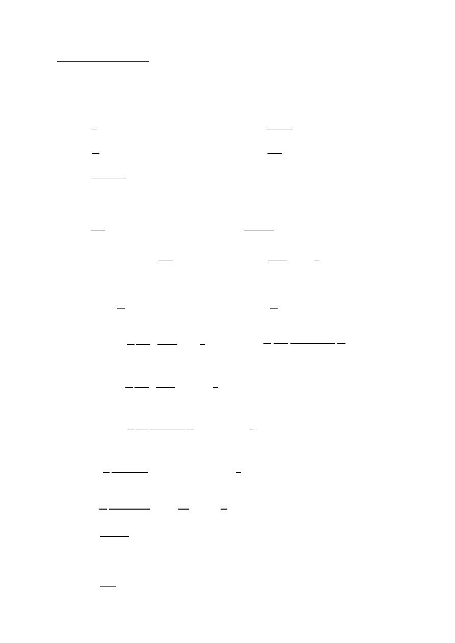
Fundamental parameters of antennas
Radiation pattern:- A graphical representation of the radiation properties of
of the antenna a function of space coordinates.
∝ | |
∝ | |
Power pattern:- A graph of the received power of a constant radius.
( , ) ∝ | ( , )|
Field pattern:- A graph of the received electric or magnetic field along a constant
radius.
(
, ) normalized field pattern =
,
,
Isotropic radiator :- A hypothetical antenna having equal radiation in all direction
(point source).
Directional antenna:- An antenna having the property of radiating or receiving
electromagnetic waves more effectively in some directions
than others.
Omni directional antenna:- An antenna having a non directional pattern in azimuth
and a directional in elevation.
Azimuth plane ( ( ) ,
= constant )
=
2
elevation plane ( ( ) ,
= constant )
= 0
=
2
Radiation pattern lopes
Radiating lobes:- A portion of the radiation pattern bounded by the regions of
relatively weak direction intensity.
xz plane
yz plane
xy plane
x
y
z
First null beam width
( FNBW )
Half-power beam width
( HPBW )
Major lobe
Side lobe
Back lobe
Minor lobes
Minor lobes
y
x
z
34
ﺎﺋﯿﺔــﺑﺮﮭﻜﻟا ﺔﺳﺪﻨﮭﻟا ﻢﺴﻗ ﻞــــﺻﻮﻤﻟا ﺔﻌﻣﺎﺟ
ﺎﻻتــﺼﺗﻻاو ﻚـــﯿﻧوﺮﺘﻜﻟﻻا عﺮـــــــــــــــﻓ
ﺎروديــﺒﻟا ﺪﻤﺤﻣ ﺪﯾﺆﻣ ناوﺮﻣ ﺐﻟﺎﻄﻟا داﺪﻋا
Side lobes:- A radiating lobe in any direction other than the intended lobe
( usually side lobes is adjacent to the main lobe).
Back lobe:- A minor lobe that occupies the hemisphere in the direction apposite
to that of the major lobe.
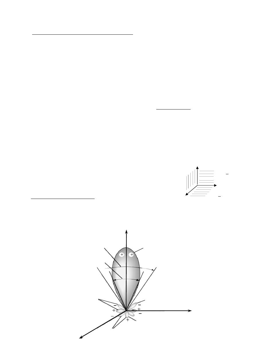
Field region
< 0.62
3
reactive near field region .
>
≥ 0.62
radiating near
>
2
2
for field region .
D: The largest dimension of the antenna .
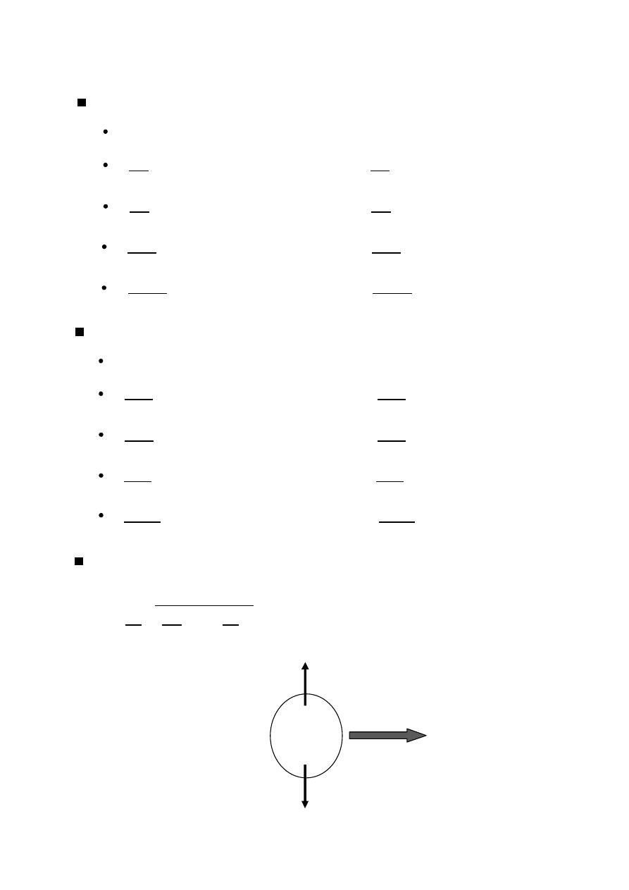
Radiation power density
W⃗
=
1
2
⃗
⊗
⃗
=
W⃗
.
⃗ where
⃗ =
⃗
=
1
2
⃗
⊗
⃗
.
⃗
W⃗ : The time average poynting vector
or average power density.
:The radiated power (watt)
defined as the power radiated from
Radiation intensity is
-
:
Radiation intensity
an antenna per unit solid angle .
(
, )
=
W
The radiation intensity is also related to the far-zone electric field of an antenna
by
U ∝ | | .
(
, )
=
W
(
, )
=
1
2
⃗
⊗
⃗
, =
⟹
=
( , )
=
1
2
(
, )
=
2
2
| ( , )| where = 120
=
∫ ∫ ( , )
Ω where Ω
=
=
∫ ∫ ( , )
watt
Unit solid angle
field region .
Far-field(Fraunhofer) region
Radiating near-field(Fresnel) region
Reactive
near-field region
D
R
R
2
1
*
*
*
35
ﺎﺋﯿﺔــﺑﺮﮭﻜﻟا ﺔﺳﺪﻨﮭﻟا ﻢﺴﻗ ﻞــــﺻﻮﻤﻟا ﺔﻌﻣﺎﺟ
ﺎﻻتــﺼﺗﻻاو ﻚـــﯿﻧوﺮﺘﻜﻟﻻا عﺮـــــــــــــــﻓ
ﺎروديــﺒﻟا ﺪﻤﺤﻣ ﺪﯾﺆﻣ ناوﺮﻣ ﺐﻟﺎﻄﻟا داﺪﻋا
Directivity
Directive gain in a given direction is the ratio of the radiation intensity in that
direction to the radiation intensity of a reference antenna (isotropic antenna).
( , )
=
4
,
=
( , )
=
4
,
( , )
=
4
,
,
Ω
=
4
2
2
2
2
2
2
0
2
0
( , )
=
4
2
2
2
0
=
2
2
2
0
=
2
2
( )
=
4
( , ): directive gain in a given direction.
(
, ): radiation intensity in a given direction .
(
, )|
: maximum radiation intensity
: radiation intensity of isotropic antenna .
: radiated power.
Gain:- power gain of an antenna in a given direction is defined as
4 times the ratio
of radiation intensity in that direction to the net power accepted by
the antenna from a connected transmitter.
( , )
=
4
,
Efficiency
η =
%
( , )
=
4
,
η
( , )
=
( , )
η
( , )
=
( , )
=
η
36
ﺎﺋﯿﺔــﺑﺮﮭﻜﻟا ﺔﺳﺪﻨﮭﻟا ﻢﺴﻗ ﻞــــﺻﻮﻤﻟا ﺔﻌﻣﺎﺟ
ﺎﻻتــﺼﺗﻻاو ﻚـــﯿﻧوﺮﺘﻜﻟﻻا عﺮـــــــــــــــﻓ
ﺎروديــﺒﻟا ﺪﻤﺤﻣ ﺪﯾﺆﻣ ناوﺮﻣ ﺐﻟﺎﻄﻟا داﺪﻋا
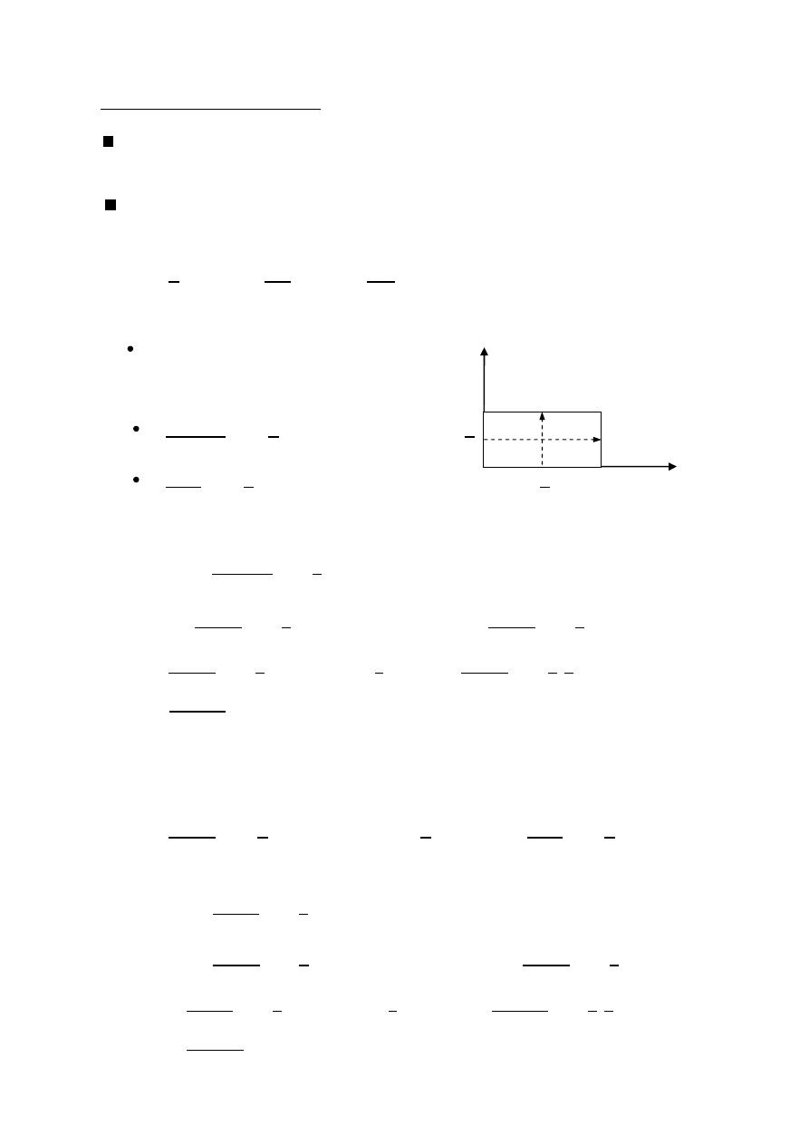
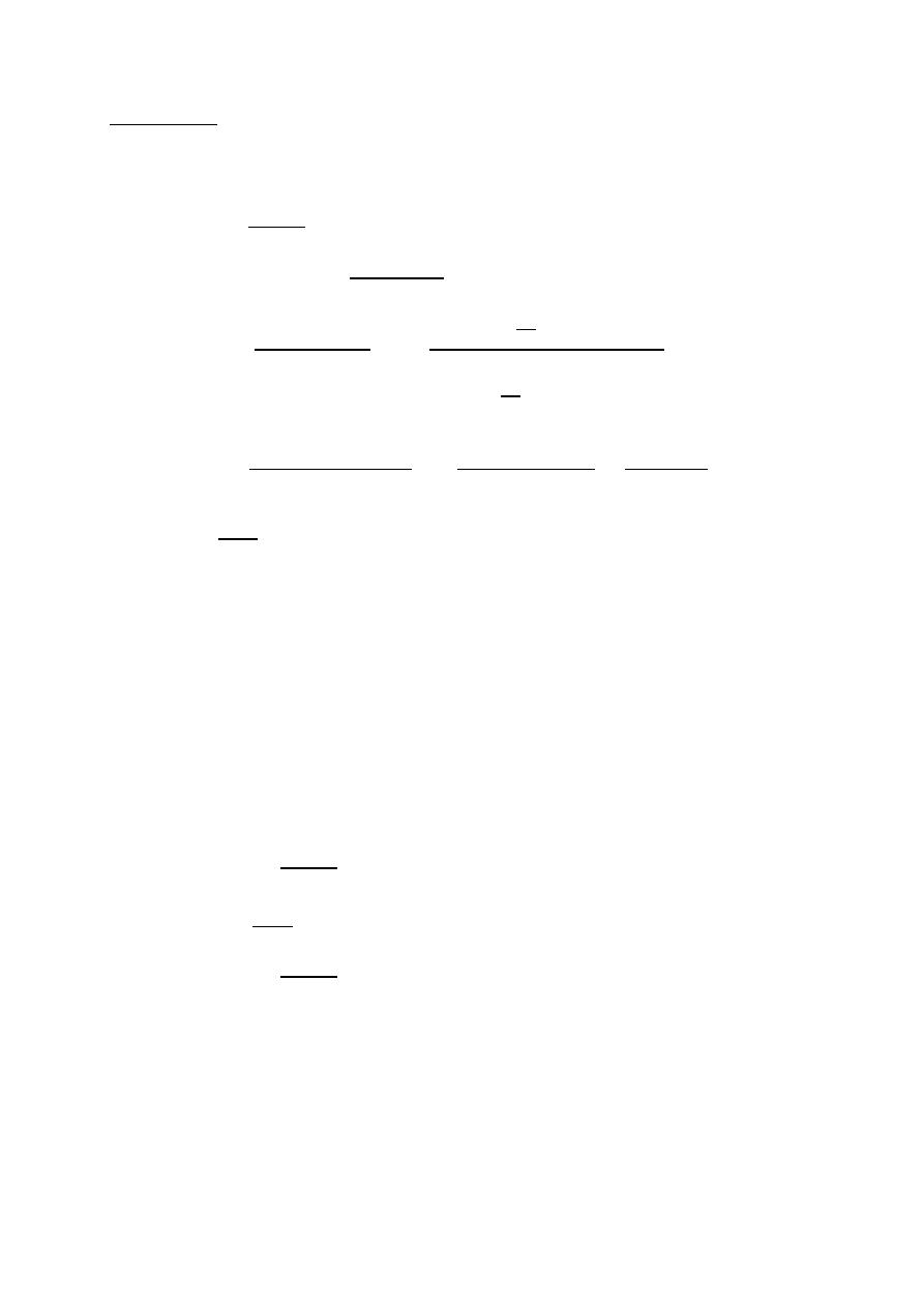
(HPBW)
Half Power Beam Width
Is the angular separation of the points where the main beam of the power pattern
equals one half the maximum value. on the field pattern these points corresponding
to the value
√
.
Field pattern Power pattern
(
, )
=
10
0.707(
)
=
( , )
0.707(10)
=
10
ℎ
=
0.707
=
0.707
=
45
HPBW
=
2(90 −
ℎ
)
HPBW
=
2(90 − 45
)
HPBW
=
90
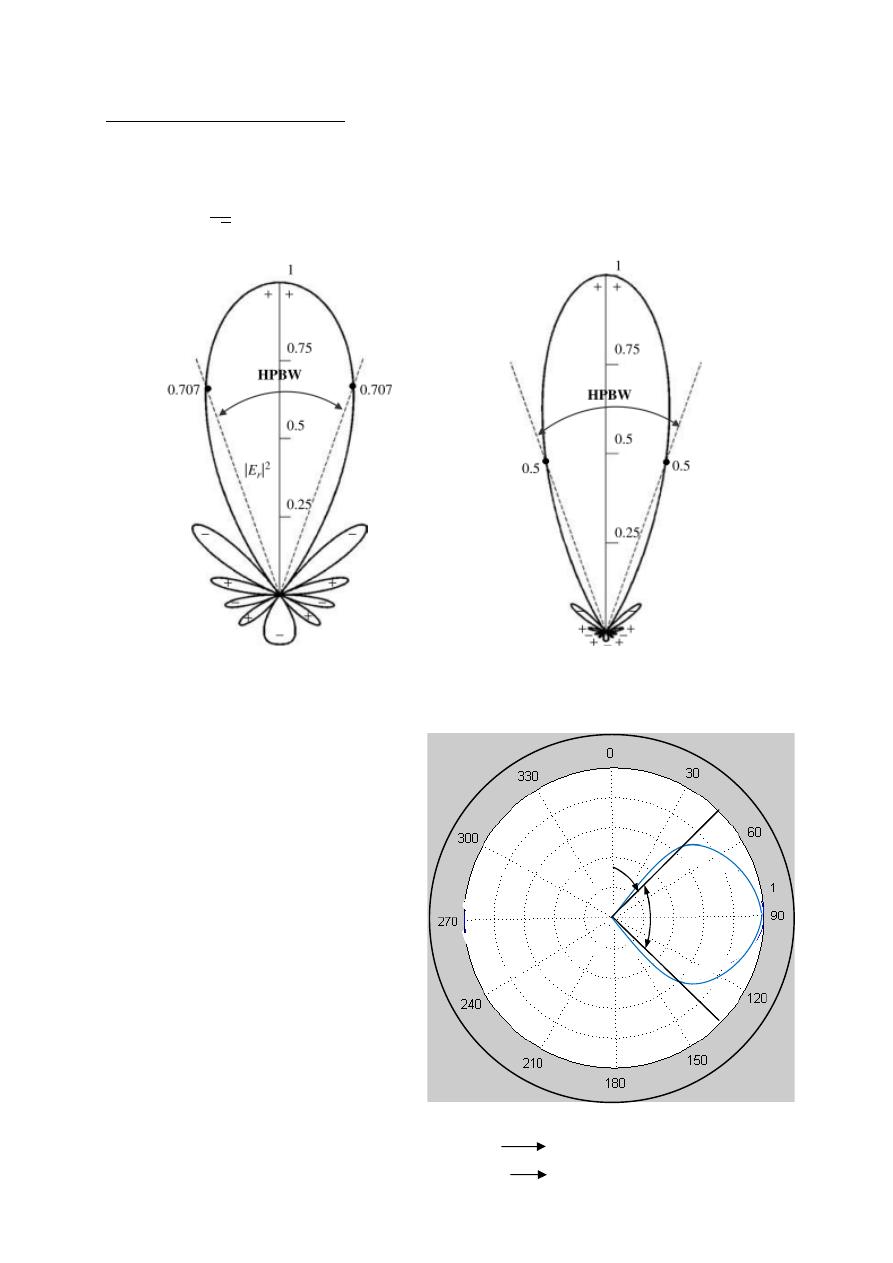
or normalization
(
, )
=
0.707(
)
=
( , )
0.707(1)
=
ℎ
=
0.707
=
0.707
=
45
HPBW
=
2(90 −
ℎ
)
HPBW
=
2(90 − 45
)
note: Field 0.5
HPBW
=
90
power 0.707
45º
37
ﺎﺋﯿﺔــﺑﺮﮭﻜﻟا ﺔﺳﺪﻨﮭﻟا ﻢﺴﻗ ﻞــــﺻﻮﻤﻟا ﺔﻌﻣﺎﺟ
ﺎﻻتــﺼﺗﻻاو ﻚـــﯿﻧوﺮﺘﻜﻟﻻا عﺮـــــــــــــــﻓ
ﺎروديــﺒﻟا ﺪﻤﺤﻣ ﺪﯾﺆﻣ ناوﺮﻣ ﺐﻟﺎﻄﻟا داﺪﻋا
(
, )
=
10
0.707(
)
=
( , )
0.707(1)
=
ℎ
=
0.707
=
0.707
=
45
HPBW
=
2|0 −
ℎ
|
HPBW
=
2|0 − 45 |
HPBW
=
90
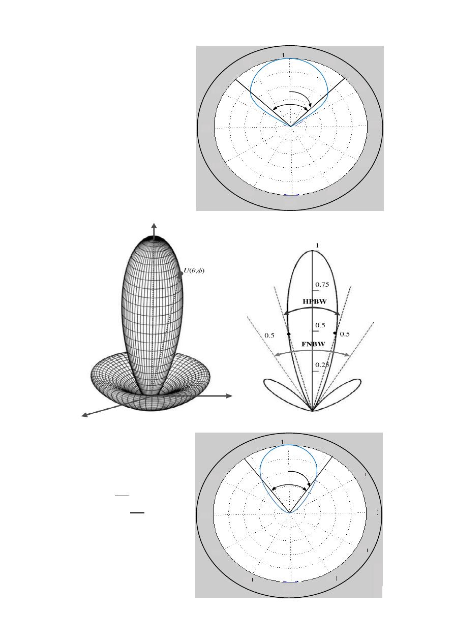
( , )
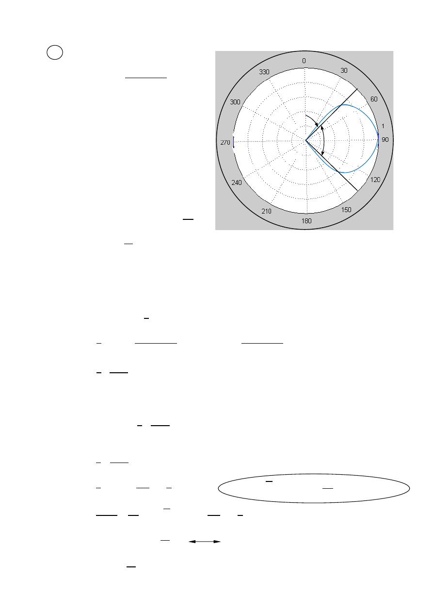
=
3
0.5(
)
=
( , )
0.5(1)
=
3
ℎ
= √
0.5
=
√
0.5
=
37.5
HPBW
=
2|0 −
ℎ
|
HPBW
=
2|0 − 37.5 |
HPBW
=
75
0
30
150
300
60
120
90
330
270
180
210
240
45º
330
270
240
210
180
150
120
90
60
30
0
300
x
y
z
37.5º
=
y
z
x
38
ﺎﺋﯿﺔــﺑﺮﮭﻜﻟا ﺔﺳﺪﻨﮭﻟا ﻢﺴﻗ ﻞــــﺻﻮﻤﻟا ﺔﻌﻣﺎﺟ
ﺎﻻتــﺼﺗﻻاو ﻚـــﯿﻧوﺮﺘﻜﻟﻻا عﺮـــــــــــــــﻓ
ﺎروديــﺒﻟا ﺪﻤﺤﻣ ﺪﯾﺆﻣ ناوﺮﻣ ﺐﻟﺎﻄﻟا داﺪﻋا
(B.W)
Band Width
The range of frequency with which the performance of the antenna with respect to
some characteristic conforms to a specified standard .
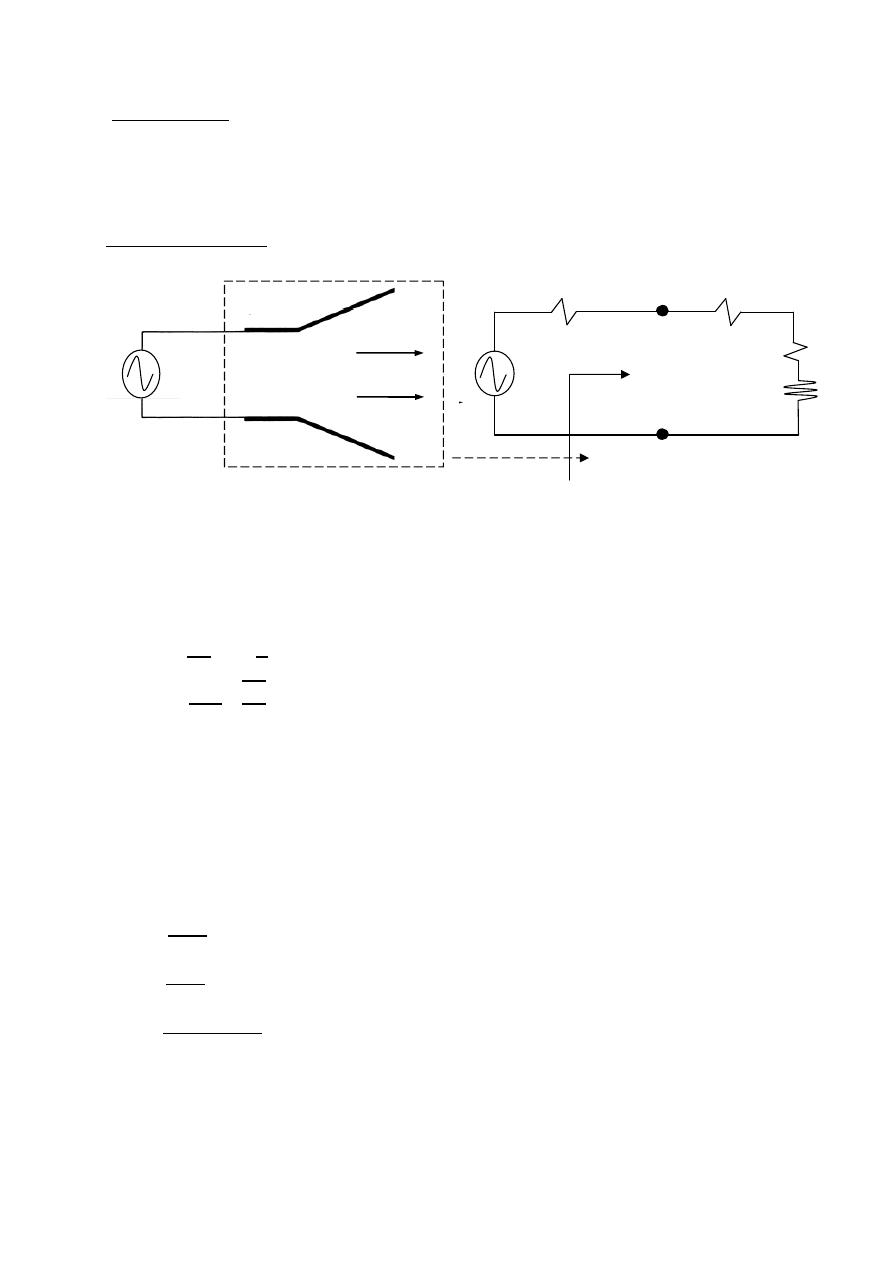
Input impedance
A: Antenna
=
+
=
+
=
=
For dc resistance
=
2
2
For high frequencies
L: length of antenna .
a: radius of the antenna .
=
2
=
:
conductivity
of the antenna
=
=
=
+
Antenna
a
a
b
Radiated
Wave
R
s
R
Loss
R
rad
x
A
V
s
V
s
Equivalent circuit
i/p impedance
A
Z
39
ﺎﺋﯿﺔــﺑﺮﮭﻜﻟا ﺔﺳﺪﻨﮭﻟا ﻢﺴﻗ ﻞــــﺻﻮﻤﻟا ﺔﻌﻣﺎﺟ
ﺎﻻتــﺼﺗﻻاو ﻚـــﯿﻧوﺮﺘﻜﻟﻻا عﺮـــــــــــــــﻓ
ﺎروديــﺒﻟا ﺪﻤﺤﻣ ﺪﯾﺆﻣ ناوﺮﻣ ﺐﻟﺎﻄﻟا داﺪﻋا
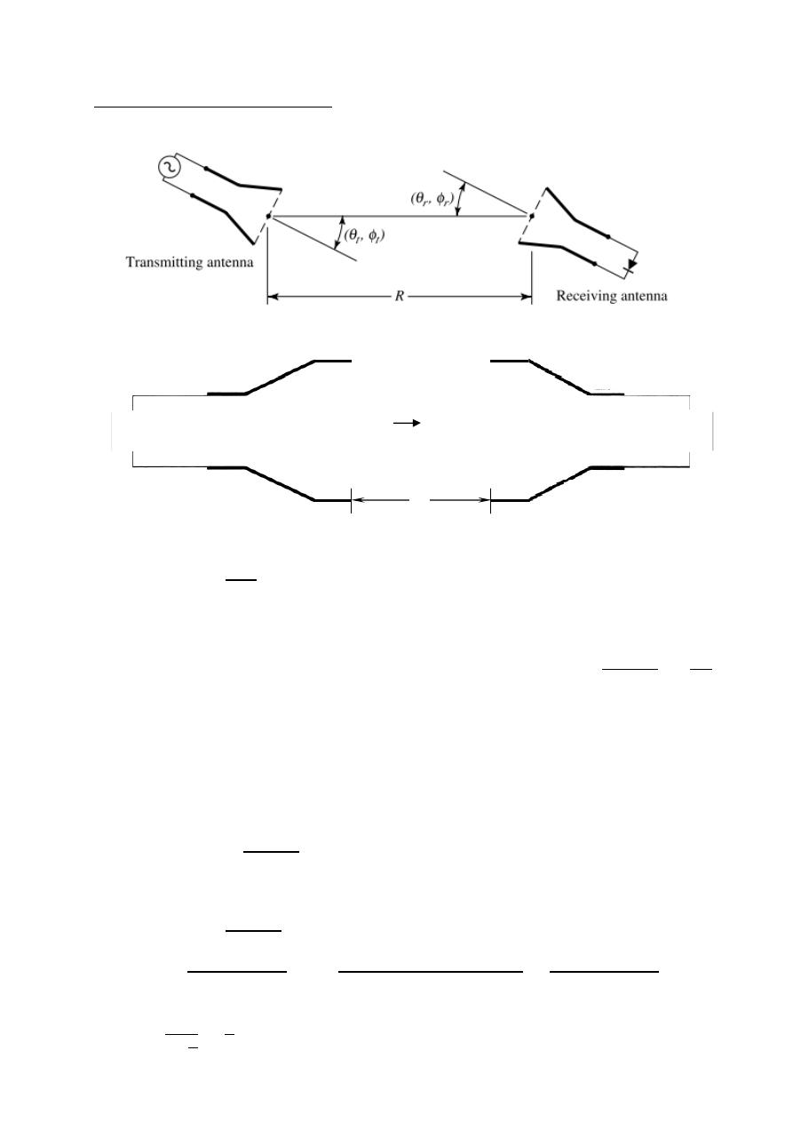
Friis Transmission equation
=
4
2
: received power
Ex:-
The radiated power density of an antenna is given by
⃗
=
2
⃗
2
Determine:
1-The total radiated power.
2-radiation intensity.
3-Directivity.
The solution:-
=
W⃗
.
⃗
⃗ =
⃗
1-
=
2
⃗
0
2
0
.
2
⃗
=
2
2
0
=
watt
2- (
, )
=
W
(
, )
=
2
=
3-
=
4
,
,
Ω
=
4
0
2
0
=
4
2
2
0
=
4
2
2
=
4
=
1.27
Transmitting antenna
Receiving antenna
T
R
G
P
P
P
G
r
x
r
t
t
x
P
in
=P
t
+ P
Loss
P
in
=P
rad
+ P
Loss
R
P
r
, G
r
, D
r
)
(
P
t
, G
t
, D
t
)
(
40
ﺎﺋﯿﺔــﺑﺮﮭﻜﻟا ﺔﺳﺪﻨﮭﻟا ﻢﺴﻗ ﻞــــﺻﻮﻤﻟا ﺔﻌﻣﺎﺟ
ﺎﻻتــﺼﺗﻻاو ﻚـــﯿﻧوﺮﺘﻜﻟﻻا عﺮـــــــــــــــﻓ
ﺎروديــﺒﻟا ﺪﻤﺤﻣ ﺪﯾﺆﻣ ناوﺮﻣ ﺐﻟﺎﻄﻟا داﺪﻋا
Ex:-
The radiated power density of an antenna is given by by
⃗
=
2
2
⃗
w
2
Determine:
1-The total radiated power.
2-radiation intensity.
3-Directivity.
The solution:-
=
W⃗
.
⃗ nete:-
∫
3
=
4
3
1-
=
2
2
⃗
0
2
0
.
2
⃗
=
2
3
0
=
8
3
watt
2- (
, )
=
W
(
, )
=
2
2
=
2
3-
=
4
,
,
Ω
=
4
2
0
2
0
=
4
2
3
0
=
4
2
4
3
=
3
2
=
1.5
Ex:-
An antenna has a field pattern given by ( )
=
2 for 0 ≤
≤ 90
Find HPBW .
The solution:-
0.707(max)
=
2 ( )
0.707(1)
=
2
=
0.707
2
=
0.707
2
=
20.5
HPBW
=
2
×
20.5
o
=
41
o
Ex:-
The radiation intensity of an antenna is represented by ( )
=
3
for
0 ≤
≤ 90 Find HPBW .
The solution:-
0.5(max)
=
3 ( )
0.5
=
3
0.707
=
3
=
0.707
3
=
0.707
2
=
14.375
HPBW
=
2
×
14.375
o
=
28.75
o
0 1
30° 0.75
45° 0.5
60° 0.25
90° 0
0 1
30° 0.75
45° 0.5
60° 0.25
90° 0
41
ﺎﺋﯿﺔــﺑﺮﮭﻜﻟا ﺔﺳﺪﻨﮭﻟا ﻢﺴﻗ ﻞــــﺻﻮﻤﻟا ﺔﻌﻣﺎﺟ
ﺎﻻتــﺼﺗﻻاو ﻚـــﯿﻧوﺮﺘﻜﻟﻻا عﺮـــــــــــــــﻓ
ﺎروديــﺒﻟا ﺪﻤﺤﻣ ﺪﯾﺆﻣ ناوﺮﻣ ﺐﻟﺎﻄﻟا داﺪﻋا
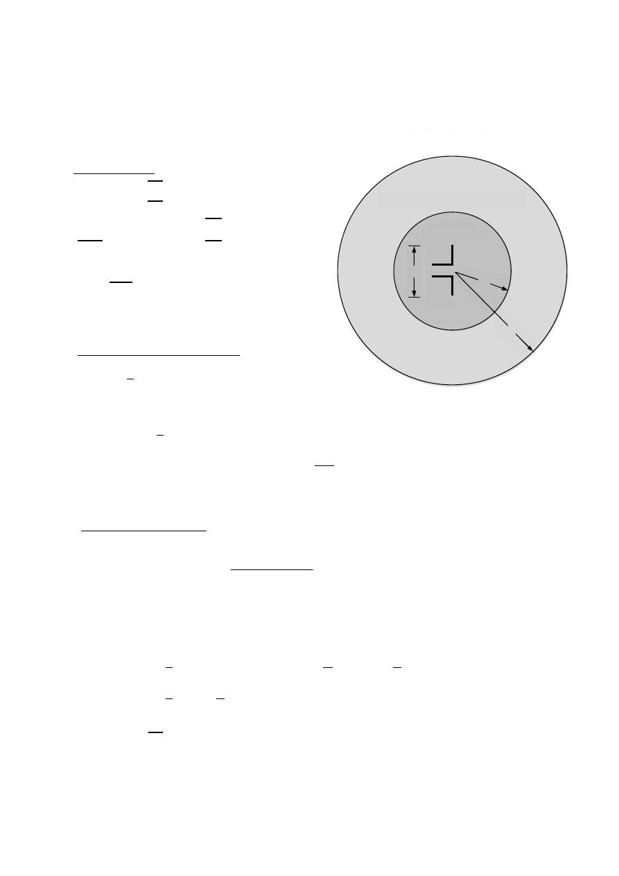
Linear Wire Antenna
Wire Antennas (Linear or Curved) are some of the oldest , simplest , cheapest ,
and in many cases the most versatile for many application.
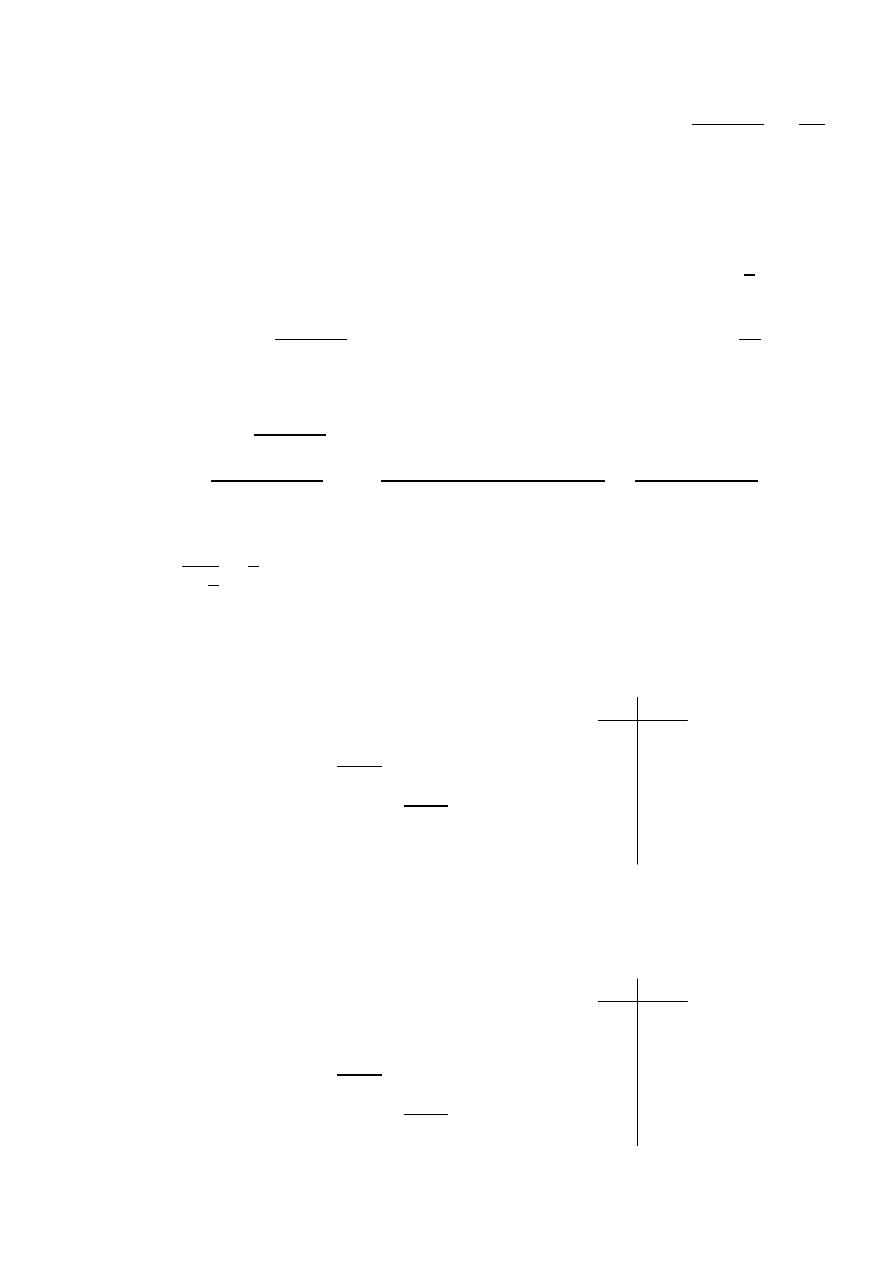
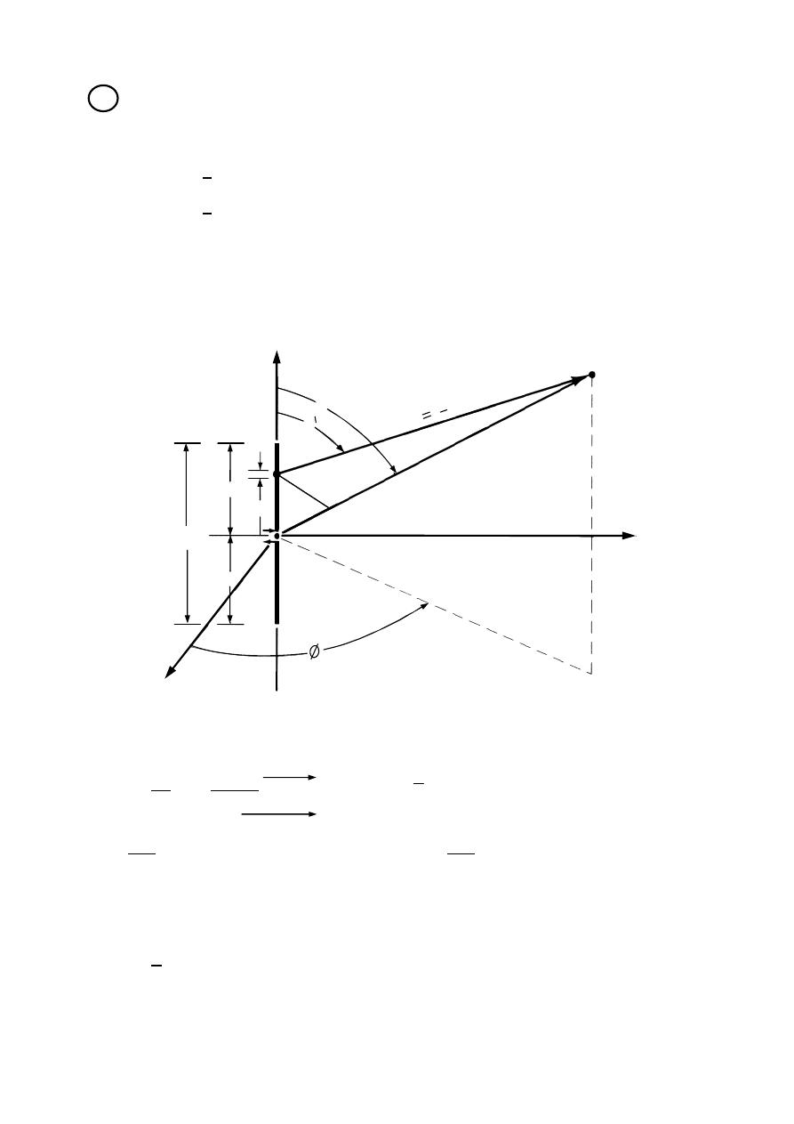
Infinitesimal dipole (
≪ )
Short dipole current element (
≤ /50)
The current is assumed to be constant and given by:
( )⃗
=
⃗ (
=
constant)
Radiated fields it will be required to determine first
A⃗ (magnetic vector potential)
And then find
E⃗ & H⃗ at P
.
⃗
=
⃗ +
⃗ +
⃗
1
Infinitesimal dipole
P
Z
x y-
plane
Z
x
y
r cos
θ
r sin
θ
O

42
ﺎﺋﯿﺔــﺑﺮﮭﻜﻟا ﺔﺳﺪﻨﮭﻟا ﻢﺴﻗ ﻞــــﺻﻮﻤﻟا ﺔﻌﻣﺎﺟ
ﺎﻻتــﺼﺗﻻاو ﻚـــﯿﻧوﺮﺘﻜﻟﻻا عﺮـــــــــــــــﻓ
ﺎروديــﺒﻟا ﺪﻤﺤﻣ ﺪﯾﺆﻣ ناوﺮﻣ ﺐﻟﺎﻄﻟا داﺪﻋا
A⃗ is given by the following relation
A⃗
=
2
=
I
A
=
The current density ( )Integrated over the cross sectional area of wire (which is placed
on xy plane) is( ) use current I
∫
I
A
=
I
A⃗
=
4
⃗
ℓ
2
ℓ
2
A⃗
=
4
ℓ
2
−
ℓ
2
⃗
A⃗
=
ℓ
−
4
⃗ ,
=
= 0
=
ℓ
−
4
∇ × A⃗
=
B⃗
The transformation between rectangular and spherical components is given by
=
−
−
0
=
=
ℓ
4
=
−
=
−
ℓ
4
=
0
∇ × A⃗
=
B⃗
∇ × A⃗
=
1
−
⃗
+
1
1
−
⃗
+
1
(
)
−
⃗
∇ × A⃗
=
1
(
)
−
⃗
H⃗
=
ℓ
4
1
+
1
⃗
= 0
= 0
=
ℓ
4
1
+
1
J
J
J
J
43
ﺎﺋﯿﺔــﺑﺮﮭﻜﻟا ﺔﺳﺪﻨﮭﻟا ﻢﺴﻗ ﻞــــﺻﻮﻤﻟا ﺔﻌﻣﺎﺟ
ﺎﻻتــﺼﺗﻻاو ﻚـــﯿﻧوﺮﺘﻜﻟﻻا عﺮـــــــــــــــﻓ
ﺎروديــﺒﻟا ﺪﻤﺤﻣ ﺪﯾﺆﻣ ناوﺮﻣ ﺐﻟﺎﻄﻟا داﺪﻋا
in the same manner
∇ × H⃗
=
+
⃗
=
E
⃗
⟹
= 0
free space
∇ × H⃗
=
⃗
∴
=
ℓ
2
2
1
+
−
,
=
120
=
ℓ
4
1
+
1
−
1
2
= 0
≪
or
≪ 1
Near Field region
For
≪ 1 ( ≪ ) the fields can be approximated by:
= −
ℓ
−
2
3
= −
ℓ
−
4
3
=
ℓ
−
4
2
=
=
= 0
Ex:-
For infinitesimal dipole (Near field region )
prove that the average power density
W⃗
= 0
.
The solution:-
W⃗
=
1
2
⃗
⊗
⃗
W⃗
=
1
2
−
ℓ
−
2
3
⃗ ⊗
ℓ
−
4
2
⃗
= 0
W⃗
=
1
2
−
ℓ
−
4
3
⃗ ⊗
ℓ
−
4
2
⃗
= 0
≫ 1
Far Field region
=
ℓ
−
4
=
ℓ
−
4
=
=
=
= 0
J
J
J
a
b
*
44
ﺎﺋﯿﺔــﺑﺮﮭﻜﻟا ﺔﺳﺪﻨﮭﻟا ﻢﺴﻗ ﻞــــﺻﻮﻤﻟا ﺔﻌﻣﺎﺟ
ﺎﻻتــﺼﺗﻻاو ﻚـــﯿﻧوﺮﺘﻜﻟﻻا عﺮـــــــــــــــﻓ
ﺎروديــﺒﻟا ﺪﻤﺤﻣ ﺪﯾﺆﻣ ناوﺮﻣ ﺐﻟﺎﻄﻟا داﺪﻋا
Parameters of infinitesimal dipole
Radiation Resistance
W⃗
=
⃗ ⊗ ⃗
W⃗
=
1
2
ℓ
−
4
⃗
⊗ −
ℓ
+
4
⃗
W⃗
=
2
ℓ
4
2
⃗
=
W
⃗ . ⃗
⃗
=
⃗
=
ℓ
4
2
⃗ .
2
⃗
=
ℓ
4
∫
3
=
2
2
ℓ
4
4
(
2
)
= √2
,
=
2
,
=
120
=
120
2
2
√2
ℓ
4
4
(
2
)
=
80
2
ℓ
2
=
=
80
2
ℓ
2
only for
≤
50
Directivity
( , )
=
4
,
,
Ω
=
4
2
2
0
2
0
( , )
=
4
2
3
0
2
0
=
4
2
2
4
3
=
4
(1)
2
2
4
3
=
1.5
i
*
ii
45
ﺎﺋﯿﺔــﺑﺮﮭﻜﻟا ﺔﺳﺪﻨﮭﻟا ﻢﺴﻗ ﻞــــﺻﻮﻤﻟا ﺔﻌﻣﺎﺟ
ﺎﻻتــﺼﺗﻻاو ﻚـــﯿﻧوﺮﺘﻜﻟﻻا عﺮـــــــــــــــﻓ
ﺎروديــﺒﻟا ﺪﻤﺤﻣ ﺪﯾﺆﻣ ناوﺮﻣ ﺐﻟﺎﻄﻟا داﺪﻋا
HPBW
(
, )
=
ℓ
−
4
(
, )
=
0.707(
)
=
( , )
0.707(1)
=
ℎ
=
0.707
=
0.707
=
45
HPBW
=
2(90 −
ℎ
)
HPBW
=
2(90 − 45
)
HPBW
=
90
For Infinitesimal dipole
≤
50
=
80
2
ℓ
2
=
1.5
HPBW
=
90
Ex:-
Derive an expression for the radiation resistance of a short dipole antenna.
The solution:-
W⃗
=
⃗ ⊗ ⃗
W⃗
=
1
2
ℓ
−
4
⃗
⊗ −
ℓ
+
4
⃗
W⃗
=
2
ℓ
4
2
⃗
=
W
⃗ . ⃗
⃗
=
⃗
=
ℓ
4
2
⃗ .
2
⃗
=
ℓ
4
∫
3
=
2
2
ℓ
4
4
(
2
)
= √2
,
=
2
,
=
120
=
120
2
2
√2
ℓ
4
4
(
2
)
=
80
2
ℓ
2
=
=
80
2
ℓ
2
iii
45º
*
46
ﺎﺋﯿﺔــﺑﺮﮭﻜﻟا ﺔﺳﺪﻨﮭﻟا ﻢﺴﻗ ﻞــــﺻﻮﻤﻟا ﺔﻌﻣﺎﺟ
ﺎﻻتــﺼﺗﻻاو ﻚـــﯿﻧوﺮﺘﻜﻟﻻا عﺮـــــــــــــــﻓ
ﺎروديــﺒﻟا ﺪﻤﺤﻣ ﺪﯾﺆﻣ ناوﺮﻣ ﺐﻟﺎﻄﻟا داﺪﻋا
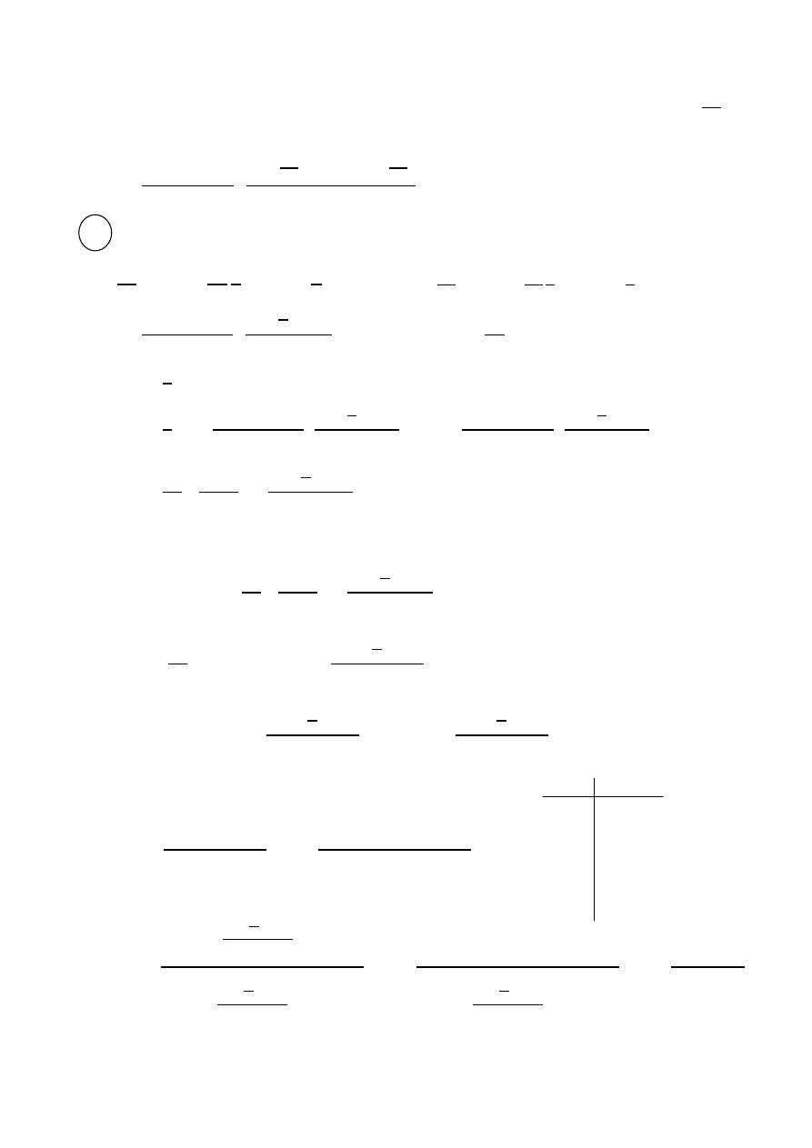
Finite Length dipole (
> /10)
Assume sinusoidal current distribution
=
2
−
> 0
=
2
+
< 0
The current is zero at the ends of the dipole since the current in the z-direction
The magnetic vector potential
A⃗ is also in the z-direction
=
4
−
=
∫
0
−
(
+
)
− ( −
)
+
∫
0
( − )
− ( −
)
Where L : dipole length
H : Half dipole length
= H
2
r
θ
θ
x
Z
y
H
H
dz
z
P
Finite Length dipole
R = ( r z cosθ) for phase
R = r for amplitude
L
R
r
c
θ
o
s
θ
o
c
o
z
s
47
ﺎﺋﯿﺔــﺑﺮﮭﻜﻟا ﺔﺳﺪﻨﮭﻟا ﻢﺴﻗ ﻞــــﺻﻮﻤﻟا ﺔﻌﻣﺎﺟ
ﺎﻻتــﺼﺗﻻاو ﻚـــﯿﻧوﺮﺘﻜﻟﻻا عﺮـــــــــــــــﻓ
ﺎروديــﺒﻟا ﺪﻤﺤﻣ ﺪﯾﺆﻣ ناوﺮﻣ ﺐﻟﺎﻄﻟا داﺪﻋا
The general expression for the distance electric field for a dipole antenna
( >
λ
10
)
Is given by:
=
60
−
2
−
2
1
=
/2 dipole :
=
=
,
(
2
)
=
cos(
2
2 2
)
=
(
2
)
= 0
⃗
=
60
−
2
⃗
,
=
W⃗
=
1
2
⃗
⊗
⃗
W⃗
=
1
2
60
−
2
⃗
⊗
− 60
2
⃗
W⃗
=
1
2
60
2
2
2
⃗
=
W
⃗ . ⃗
⃗
=
⃗
=
1
2
60
2
2
2
⃗
0
⃗
2
0
=
1
2
(60
)
2
(
2
)
2
2
=
60
2
2
,
2
2
=
1.218
=
73
⟹
=
73 Ω ( , )
=
4
,
,
Ω
=
4
2
2
0
2
0
=
4
2
2
2
2
2
0
=
4
(1)
2
2
2
2
0
=
4
1
2
(1.218)
=
1.64
*
0 0
30° 0.417
45° 0.627
60° 0.816
90° 1
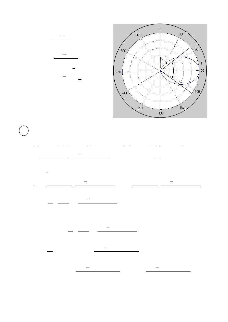
48
ﺎﺋﯿﺔــﺑﺮﮭﻜﻟا ﺔﺳﺪﻨﮭﻟا ﻢﺴﻗ ﻞــــﺻﻮﻤﻟا ﺔﻌﻣﺎﺟ
ﺎﻻتــﺼﺗﻻاو ﻚـــﯿﻧوﺮﺘﻜﻟﻻا عﺮـــــــــــــــﻓ
ﺎروديــﺒﻟا ﺪﻤﺤﻣ ﺪﯾﺆﻣ ناوﺮﻣ ﺐﻟﺎﻄﻟا داﺪﻋا
HPBW
(
, )
=
2
0.707(
)
=
( , )
0.707(1)
=
2
0.707
ℎ
=
2
=
√
2
=
51
HPBW
=
2(90 −
ℎ
)
HPBW
=
2(90 − 51
)
HPBW
=
78
2
=
/4 dipole :
=
=
,
(
2
)
=
cos(
2
2 4
)
=
(
4
)
=
0.707
⃗
=
60
−
4
−0.707
⃗
,
=
W⃗
=
1
2
⃗
⊗
⃗
W⃗
=
1
2
60
−
4
−0.707
⃗
⊗
− 60
4
−0.707
⃗
W⃗
=
1
2
60
2
4
−0.707
2
⃗
=
W
⃗ . ⃗
⃗
=
⃗
=
1
2
60
2
4
−0.707
2
⃗
0
⃗
2
0
=
1
2
(60
)
2
(
2
)
4
−0.707
2
=
60
4
−0.707
2
,
4
−0.707
2
=
0.114
=
6.84
⟹
=
6.84 Ω
45º
51º
*
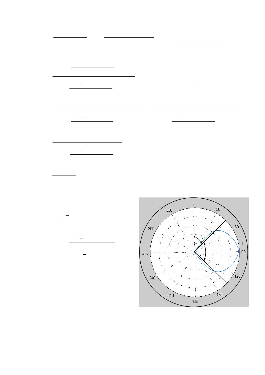
49
ﺎﺋﯿﺔــﺑﺮﮭﻜﻟا ﺔﺳﺪﻨﮭﻟا ﻢﺴﻗ ﻞــــﺻﻮﻤﻟا ﺔﻌﻣﺎﺟ
ﺎﻻتــﺼﺗﻻاو ﻚـــﯿﻧوﺮﺘﻜﻟﻻا عﺮـــــــــــــــﻓ
ﺎروديــﺒﻟا ﺪﻤﺤﻣ ﺪﯾﺆﻣ ناوﺮﻣ ﺐﻟﺎﻄﻟا داﺪﻋا
=
4
,
,
Ω
=
4
2
2
0
2
0
| ( , )|
=
4
4
−0.707
2
2
4
−0.707
2
0
=
4
(0.293)
2
2
4
−0.707
2
0
=
4
(0.293)
2
2
4
−0.707
2
2
0
=
4
(0.293)
2
2
4
−0.707
2
0
=
4
(0.293)
2
2
(0.114)
=
1.506
HPBW
(
, )
=
4
−0.707
0.707(
)
=
( , )
0.707(0.293)
=
4
−0.707
0.207
ℎ
=
4
− 0.707
=
1
0.207
− 0.707
=
46.5
HPBW
=
2(90 −
ℎ
)
HPBW
=
2(90 − 46.5
)
HPBW
=
87
45º
46.5º
0 0
30° 0.14
45° 0.2018
60° 0.25
90° 0.293
50
ﺎﺋﯿﺔــﺑﺮﮭﻜﻟا ﺔﺳﺪﻨﮭﻟا ﻢﺴﻗ ﻞــــﺻﻮﻤﻟا ﺔﻌﻣﺎﺟ
ﺎﻻتــﺼﺗﻻاو ﻚـــﯿﻧوﺮﺘﻜﻟﻻا عﺮـــــــــــــــﻓ
ﺎروديــﺒﻟا ﺪﻤﺤﻣ ﺪﯾﺆﻣ ناوﺮﻣ ﺐﻟﺎﻄﻟا داﺪﻋا
3
=
3 /4 dipole :
=
=
,
2
=
cos
2
2
3
4
=
3
4
= −
0.707
⃗
=
60
−
3
4
−(−0.707)
⃗
,
=
W⃗
=
1
2
⃗
⊗
⃗
W⃗
=
1
2
60
−
3
4
+0.707
⃗
⊗
− 60
3
4
+0.707
⃗
W⃗
=
1
2
60
2
3
4
+0.707
2
⃗
=
W
⃗ . ⃗
⃗
=
⃗
=
1
2
60
2
3
4
+0.707
2
⃗
0
⃗
2
0
=
1
2
(60
)
2
(
2
)
3
4
+0.707
2
=
60
3
4
+0.707
2
,
3
4
+0.707
2
=
3.0968
=
185.8
⟹
=
185.8 Ω
=
4
,
,
Ω
=
4
2
2
0
2
0
| ( , )|
=
4
3
4
+0.707
2
2
3
4
+0.707
2
0
=
4
(1.707)
2
2
3
4
+0.707
2
0
=
4
(1.707)
2
2
3
4
+0.707
2
0
=
4
(1.707)
2
2
(
3.0968
)
=
1.88
*
0 0
30° 0.318
45° 0.5599
60° 0.875
90° 1.707
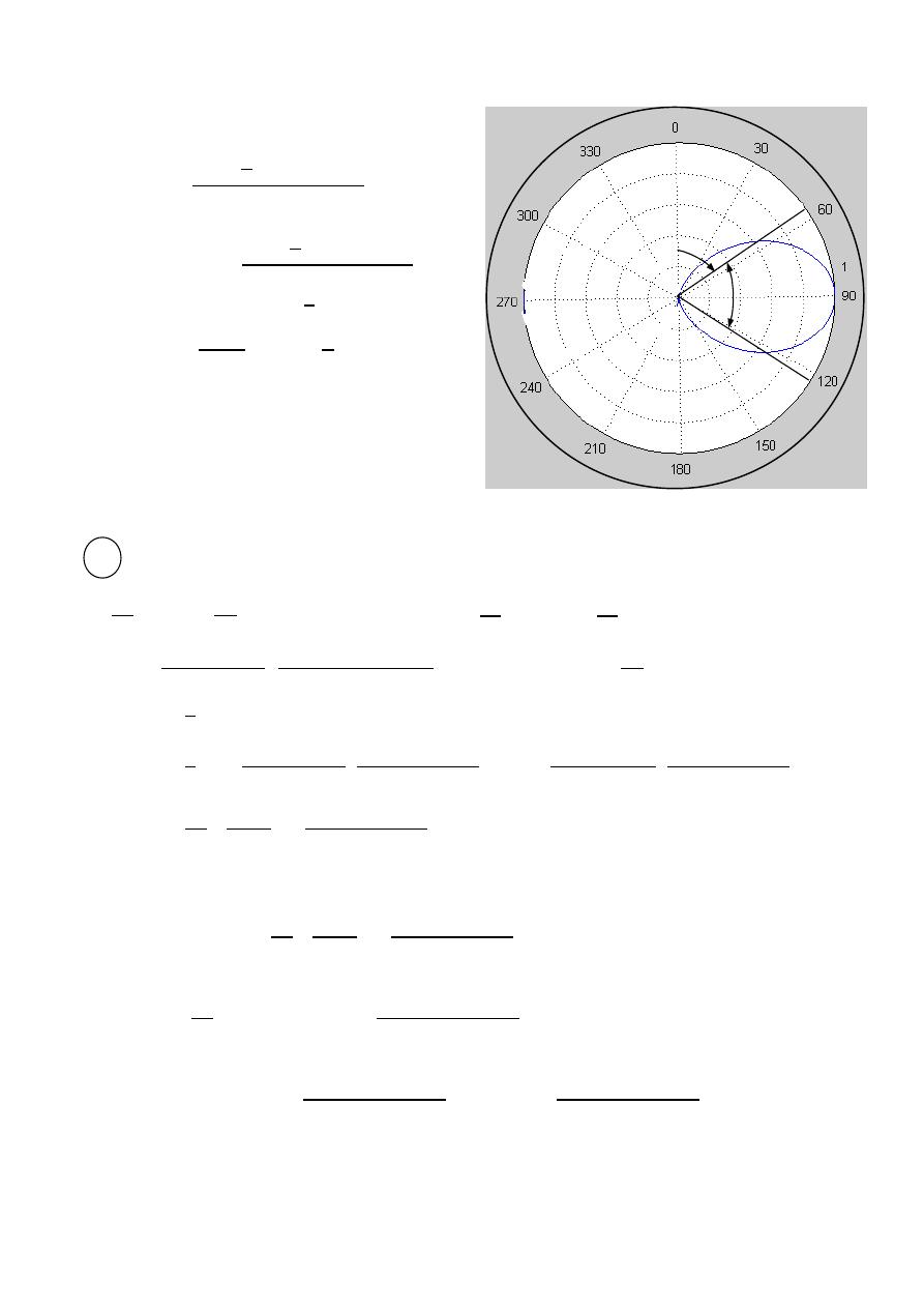
51
ﺎﺋﯿﺔــﺑﺮﮭﻜﻟا ﺔﺳﺪﻨﮭﻟا ﻢﺴﻗ ﻞــــﺻﻮﻤﻟا ﺔﻌﻣﺎﺟ
ﺎﻻتــﺼﺗﻻاو ﻚـــﯿﻧوﺮﺘﻜﻟﻻا عﺮـــــــــــــــﻓ
ﺎروديــﺒﻟا ﺪﻤﺤﻣ ﺪﯾﺆﻣ ناوﺮﻣ ﺐﻟﺎﻄﻟا داﺪﻋا
HPBW
(
, )
=
3
4
+0.707
0.707(
)
=
( , )
0.707(1.707)
=
3
4
+0.707
1.2068
ℎ
=
3
4
+ 0.707
=
−1
1
1.2068
3
+ 0.707
=
57.99
HPBW
=
2(90 −
ℎ
)
HPBW
=
2(90 − 57.99
)
HPBW
=
64
4
=
dipole :
=
=
,
2
=
cos
2
2
=
( )
= −
1
⃗
=
60
−
(
)
−(−1)
⃗
,
=
W⃗
=
1
2
⃗
⊗
⃗
W⃗
=
1
2
60
−
+1
⃗
⊗
− 60
+1
⃗
W⃗
=
1
2
60
2
+1 2
⃗
=
W
⃗ . ⃗
⃗
=
⃗
=
1
2
60
2
+1 2
⃗
0
⃗
2
0
=
1
2
(60
)
2
(
2
)
+1
2
=
60
+1
2
,
+1
2
=
3.31
=
198. 6
⟹
=
198.6 Ω
45º
57.99º
*
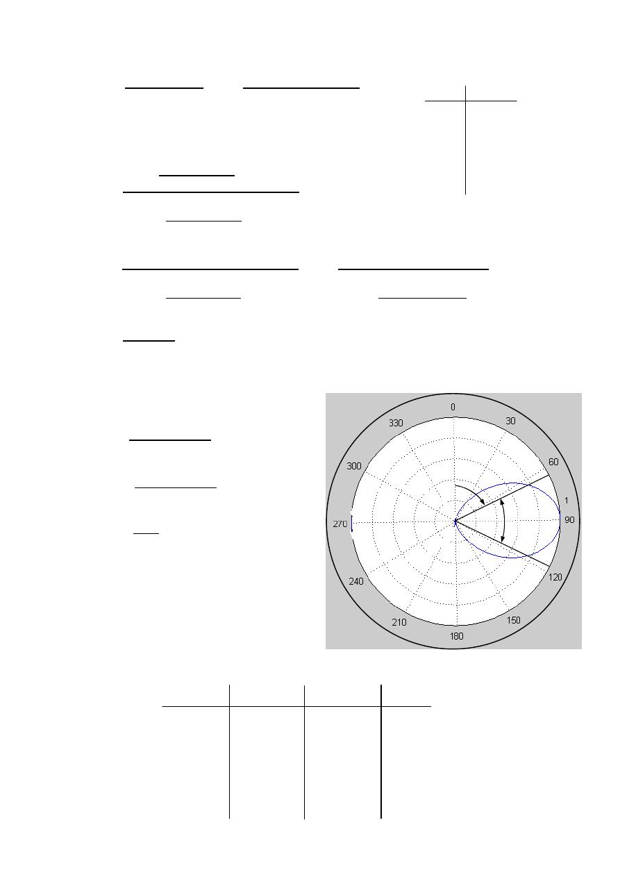
52
ﺎﺋﯿﺔــﺑﺮﮭﻜﻟا ﺔﺳﺪﻨﮭﻟا ﻢﺴﻗ ﻞــــﺻﻮﻤﻟا ﺔﻌﻣﺎﺟ
ﺎﻻتــﺼﺗﻻاو ﻚـــﯿﻧوﺮﺘﻜﻟﻻا عﺮـــــــــــــــﻓ
ﺎروديــﺒﻟا ﺪﻤﺤﻣ ﺪﯾﺆﻣ ناوﺮﻣ ﺐﻟﺎﻄﻟا داﺪﻋا
=
4
,
,
Ω
=
4
2
2
0
2
0
| ( , )|
=
4
+1
2
2
+1
2
0
=
4
(2)
2
2
+1
2
0
=
4
(2)
2
2
+1
2
0
=
4
4
2
(
3.3
1)
=
2.41
HPBW
(
, )
=
+1
0.707(
)
=
( , )
0.707(2)
=
+1
1.414
ℎ
=
(
) + 1
=
−1
1
1.414
[
(
)
+ 1
]
=
66.08
HPBW
=
2(90 −
ℎ
)
HPBW
=
2(90 − 66
)
HPBW
=
48
Length HPBW
D
L = /50 90° very small 1.5
L = /4 87° 6.84 1.52
L = /2 78° 73 1.64
L =3 /4 64° 185.8 1.88
L =
48° 198 2.41
45º
66º
0 0
30° 0.174
45° 0.5572
60° 1.1547
90° 2

53
ﺎﺋﯿﺔــﺑﺮﮭﻜﻟا ﺔﺳﺪﻨﮭﻟا ﻢﺴﻗ ﻞــــﺻﻮﻤﻟا ﺔﻌﻣﺎﺟ
ﺎﻻتــﺼﺗﻻاو ﻚـــﯿﻧوﺮﺘﻜﻟﻻا عﺮـــــــــــــــﻓ
ﺎروديــﺒﻟا ﺪﻤﺤﻣ ﺪﯾﺆﻣ ناوﺮﻣ ﺐﻟﺎﻄﻟا داﺪﻋا
Ex:-
A
λ/4 transmitting dipole antenna of 4mm radius situated with its at origin
radiates a power of 200W at a frequency of 100 MHz . determine:
1-The current fed to the dipole.
2-Directivity
3-HPBW
4-The electric field at (2 Km , 30° , 60°). Assume
=
58
MS/m
If a second λ/4 dipole is placed at 1 Km away from the transmitting antenna in
the direction of maximum radiation, find the received power at the terminal of
the second (receiving) dipole.
The solution:-
=
60
−
2
−
2
1
-
=
=
,
(
2
)
=
cos(
2
2 4
)
=
(
4
)
=
0.707
⃗
=
60
−
4
−0.707
⃗
,
=
W⃗
=
1
2
⃗
⊗
⃗
W⃗
=
1
2
60
−
4
−0.707
⃗
⊗
− 60
4
−0.707
⃗
W⃗
=
1
2
60
2
4
−0.707
2
⃗
=
W
⃗ . ⃗
⃗
=
⃗
=
1
2
60
2
4
−0.707
2
⃗
0
⃗
2
0
=
1
2
(60
)
2
(
2
)
4
−0.707
2
=
60
4
−0.707
2
,
4
−0.707
2
=
0.114
200
=
6.84
⟹
=
200
6.84
=
5.4
A
| ( , )|
2-
=
4
,
,
Ω
=
4
2
2
0
2
0
*
0 0
30° 0.14
45° 0.2018
60° 0.25
90° 0.293
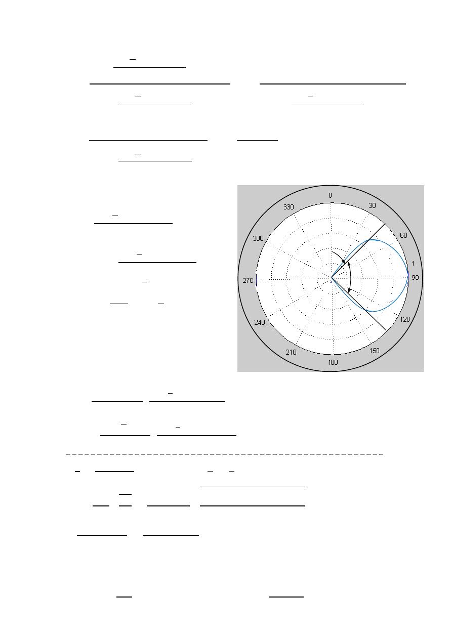
54
ﺎﺋﯿﺔــﺑﺮﮭﻜﻟا ﺔﺳﺪﻨﮭﻟا ﻢﺴﻗ ﻞــــﺻﻮﻤﻟا ﺔﻌﻣﺎﺟ
ﺎﻻتــﺼﺗﻻاو ﻚـــﯿﻧوﺮﺘﻜﻟﻻا عﺮـــــــــــــــﻓ
ﺎروديــﺒﻟا ﺪﻤﺤﻣ ﺪﯾﺆﻣ ناوﺮﻣ ﺐﻟﺎﻄﻟا داﺪﻋا
=
4
4
−0.707
2
2
4
−0.707
2
0
=
4
(0.293)
2
2
4
−0.707
2
0
=
4
(0.293)
2
2
4
−0.707
2
0
=
4
(0.293)
2
2
(0.114)
=
1.506
3- HPBW
(
, )
=
4
−0.707
0.707(
)
=
( , )
0.707(0.293)
=
4
−0.707
0.207
ℎ
=
4
− 0.707
=
1
0.207
− 0.707
=
46.5
HPBW
=
2(90 −
ℎ
)
HPBW
=
2(90 − 46.5
)
HPBW
=
87
4-
=
60
−
4
.
|
| =
60(
√
2×5.4)
2000
4
.
=
32.3m V/m
=
c
F
=
3×10
8
100×10
6
=
3m
,
=
4
=
3
4
=
0.75m
=
2
2
=
0.75
2 (0.004)
2 ×100×10
6
×4 ×10
−7
2×58×10
6
=
0.0778
=
+
=
6.84
6.84
+
0.0778
=
98.87%
=
=
0.9887 × 1.506
=
1.488
=
=
1.488 the same dipole
=
4
2
=
200 × 1.488 × 1.488 ×
3
4
×
1000
2
=
25.23
W
45º
46.5º
55
ﺎﺋﯿﺔــﺑﺮﮭﻜﻟا ﺔﺳﺪﻨﮭﻟا ﻢﺴﻗ ﻞــــﺻﻮﻤﻟا ﺔﻌﻣﺎﺟ
ﺎﻻتــﺼﺗﻻاو ﻚـــﯿﻧوﺮﺘﻜﻟﻻا عﺮـــــــــــــــﻓ
ﺎروديــﺒﻟا ﺪﻤﺤﻣ ﺪﯾﺆﻣ ناوﺮﻣ ﺐﻟﺎﻄﻟا داﺪﻋا
Ex
:- A half wave dipole is radiating into free space. The coordinate system
is defined so that the origin is at the center of the dipole and the z-axis
is aligned with the dipole. input power to the dipole is 100W. assuming
an overall efficiency of 50%, find the power density at (500 m , 60° , 0°).
The solution:-
=
60
−
2
−
2
half wave dipole(
H)
=
⟹
=
=
,
(
2
)
=
cos(
2
2 2
)
=
(
2
)
=
0
⃗ =
60
−
2
⃗
,
=
W⃗
=
1
2
⃗
⊗
⃗
W⃗
=
1
2
60
−
2
⃗
⊗
− 60
2
⃗
W⃗
=
1
2
60
2
2
2
⃗
=
W
⃗ . ⃗
⃗
=
⃗
=
1
2
60
2
2
2
⃗
0
⃗
2
0
=
1
2
(60
)
2
(
2
)
2
2
=
60
2
2
,
2
2
=
1.218
=
73
⟹
=
73
=
+
⟹
=
⟹
=
=
73
0.5
=
146
=
⟹
=
100
146
=
0.83
A
W⃗
=
1
2
60
2
2
2
⃗
W⃗
=
1
2(120 )
60×0.83 2
500
2
2
60
60
2
⃗
W⃗
=
17.5
w
m
2
⃗
*
56
ﺎﺋﯿﺔــﺑﺮﮭﻜﻟا ﺔﺳﺪﻨﮭﻟا ﻢﺴﻗ ﻞــــﺻﻮﻤﻟا ﺔﻌﻣﺎﺟ
ﺎﻻتــﺼﺗﻻاو ﻚـــﯿﻧوﺮﺘﻜﻟﻻا عﺮـــــــــــــــﻓ
ﺎروديــﺒﻟا ﺪﻤﺤﻣ ﺪﯾﺆﻣ ناوﺮﻣ ﺐﻟﺎﻄﻟا داﺪﻋا
Ex:-
A 0.75m transmitting dipole antenna of 4mm radius situated with its at origin
radiates a power of 200W at a frequency of 100 MHz , if the directivity of
the antenna is 1.52 , determine. Assume
=
58
MS/m
1-The current fed to the dipole.
2-The electric field at (2 Km , 30° , 60°).
3-HPBW of the antenna.
4-The power gain.
The solution:-
=
60
−
2
−
2
=
c
F
=
3×10
8
100×10
6
=
3m
,
=
0.75
⟹
=
0.25 ⟹
=
4
1-
(
2
)
=
cos(
2
2 4
)
=
(
4
)
=
0.707
⃗ =
60
−
4
−0.707
⃗
,
=
W⃗
=
1
2
⃗
⊗
⃗
W⃗
=
1
2
60
−
4
−0.707
⃗
⊗
− 60
4
−0.707
⃗
W⃗
=
1
2
60
2
4
−0.707
2
⃗
| ( , )|
=
4
4
−0.707
2
2
4
−0.707
2
0
4
−0.707
2
=
4
(0.293)
2
2 (
1.52
)
⟹
4
−0.707
2
=
0.1129
=
W
⃗ . ⃗
⃗
=
⃗
=
1
2
60
2
4
−0.707
2
⃗
0
⃗
2
0
=
60
4
−0.707
2
200
=
6.774
⟹
=
200
6.774
=
5.4
A
*
0 0
30° 0.14
45° 0.2018
60° 0.25
90° 0.293
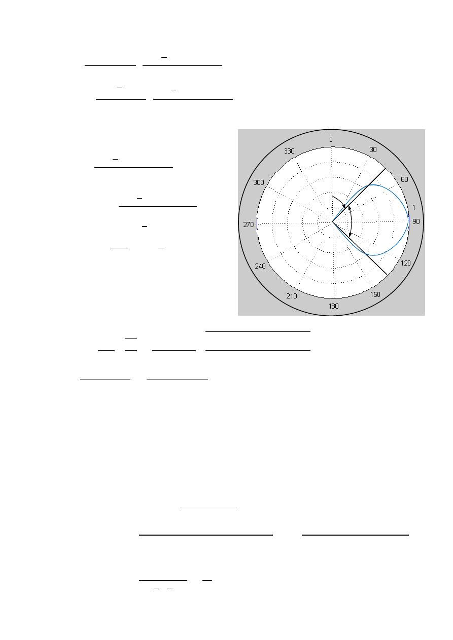
57
ﺎﺋﯿﺔــﺑﺮﮭﻜﻟا ﺔﺳﺪﻨﮭﻟا ﻢﺴﻗ ﻞــــﺻﻮﻤﻟا ﺔﻌﻣﺎﺟ
ﺎﻻتــﺼﺗﻻاو ﻚـــﯿﻧوﺮﺘﻜﻟﻻا عﺮـــــــــــــــﻓ
ﺎروديــﺒﻟا ﺪﻤﺤﻣ ﺪﯾﺆﻣ ناوﺮﻣ ﺐﻟﺎﻄﻟا داﺪﻋا
2-
⃗
=
60
−
4
−0.707
⃗
|
| =
60(
√
2×5.4)
2000
4
.
=
32.3m V/m
3- HPBW
(
, )
=
4
−0.707
0.707(
)
=
( , )
0.707(0.293)
=
4
−0.707
0.207
ℎ
=
4
− 0.707
=
1
0.207
− 0.707
=
46.5
HPBW
=
2(90 −
ℎ
)
HPBW
=
2(90 − 46.5
)
HPBW
=
87
4-
=
2
2
=
0.75
2 (0.004)
2 ×100×10
6
×4 ×10
−7
2×58×10
6
=
0.0778
=
+
=
6.774
6.774
+
0.0778
=
98.86%
=
=
0.9886 × 1.52
=
1.502
Ex:-
The radiation intensity of an antenna is given by:
(
, )
=
B
o
2
0≤ ≤ 0≤ ≤
0
Determine the directivity of the antenna.
The solution:-
( , )
=
4
,
,
Ω
( , )
=
4
B
o
2
B
o
2
0
0
=
4
2
2
2
0
0
( , )
=
4
2
2 2
=
16
45º
46.5º
elsewhere

58
ﺎﺋﯿﺔــﺑﺮﮭﻜﻟا ﺔﺳﺪﻨﮭﻟا ﻢﺴﻗ ﻞــــﺻﻮﻤﻟا ﺔﻌﻣﺎﺟ
ﺎﻻتــﺼﺗﻻاو ﻚـــﯿﻧوﺮﺘﻜﻟﻻا عﺮـــــــــــــــﻓ
ﺎروديــﺒﻟا ﺪﻤﺤﻣ ﺪﯾﺆﻣ ناوﺮﻣ ﺐﻟﺎﻄﻟا داﺪﻋا
Ex:-
For a dipole of length 2.5m operating at 120 MHz .Determine
1-Radiation resistance.
2-Directivity.
3-HPBW.
4-Radiation efficiency (assume the antenna to be made of a copper wire
of 4mm radius).
5-Gain.
6-The electric field intensity at a distance of 13 Km in the direction
of maximum radiation (assume
I = 1A ). Assume
=
58
MS/m
The solution:-
=
60
−
2
−
2
=
c
F
=
3×10
8
120×10
6
=
2.5m
,
=
.
.
⟹
=
1-
2
=
cos
2
2
=
( )
=
−1
⃗ =
60
−
(
)
+1
⃗
,
=
W⃗
=
1
2
⃗
⊗
⃗
W⃗
=
1
2
60
−
+1
⃗
⊗
− 60
+1
⃗
W⃗
=
1
2
60
2
+1 2
⃗
=
W
⃗ . ⃗
⃗
=
⃗
=
1
2
60
2
+1 2
⃗
0
⃗
2
0
=
60
+1
2
,
+1
2
=
3.316
=
198.96
⟹
=
198.96 Ω | ( , )|
2-
=
4
,
,
Ω
=
4
2
2
0
2
0
=
4
+1
2
2
+1
2
0
=
4
(2)
2
2 (
3.316
)
=
2.41
*
0 0
30° 0.174
45° 0.5572
60° 1.1547
90° 2
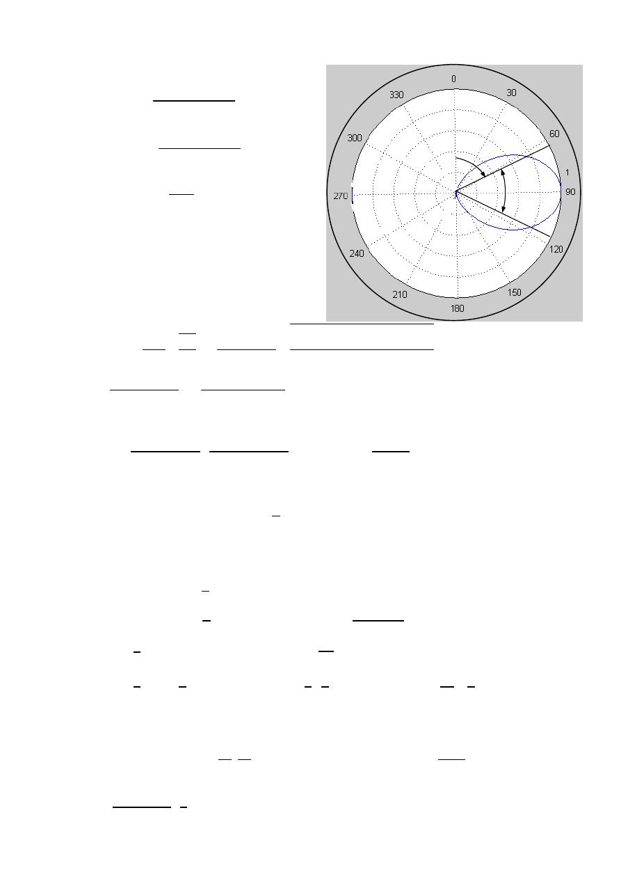
59
ﺎﺋﯿﺔــﺑﺮﮭﻜﻟا ﺔﺳﺪﻨﮭﻟا ﻢﺴﻗ ﻞــــﺻﻮﻤﻟا ﺔﻌﻣﺎﺟ
ﺎﻻتــﺼﺗﻻاو ﻚـــﯿﻧوﺮﺘﻜﻟﻻا عﺮـــــــــــــــﻓ
ﺎروديــﺒﻟا ﺪﻤﺤﻣ ﺪﯾﺆﻣ ناوﺮﻣ ﺐﻟﺎﻄﻟا داﺪﻋا
3- HPBW
(
, )
=
+1
0.707(
)
=
( , )
0.707(2)
=
+1
1.414
ℎ
=
(
) + 1
=
−1
1
1.414
[
(
)
+ 1
]
=
66.08
HPBW
=
2(90 −
ℎ
)
HPBW
=
2(90 − 66
)
HPBW
=
48
4-
=
2
2
=
2.5
2 (0.004)
2 ×120×10
6
×4 ×10
−7
2×58×10
6
=
0.285
=
+
=
198.96
198.96
+
0.285
=
99.8%
5-
=
=
0.998 × 2.41
=
2.405
6-
=
60
−
(
)
⟹
|
| =
60×1
13000
(2) =
9.23m V/m
Ex:-
A transmitting antenna located at origin has the far-electric field:
⃗ =
−
⃗
For good reception at 125 Km the amplitude of the electric field is greater
Than or equal to 100 V/m. find the minimum power needed for reception.
The solution:-
⃗
=
A
⃗
|
| =
⟹
100 × 10
−6
=
125
×
⟹
A
=
12.5
W⃗
=
1
2
⃗
⊗
⃗
,
=
W⃗
=
1
2
A
⃗
⊗
1 A
⃗
=
1
2
A
⃗
=
W
⃗ . ⃗
⃗
=
⃗
=
=
1
2
A
2
2
⃗
0
⃗
2
0
=
2 A
2
2
∫
0
=
2 (12.5)
2
2(120 )
4
3
=
1.736W
*
45º
66º
60
ﺎﺋﯿﺔــﺑﺮﮭﻜﻟا ﺔﺳﺪﻨﮭﻟا ﻢﺴﻗ ﻞــــﺻﻮﻤﻟا ﺔﻌﻣﺎﺟ
ﺎﻻتــﺼﺗﻻاو ﻚـــﯿﻧوﺮﺘﻜﻟﻻا عﺮـــــــــــــــﻓ
ﺎروديــﺒﻟا ﺪﻤﺤﻣ ﺪﯾﺆﻣ ناوﺮﻣ ﺐﻟﺎﻄﻟا داﺪﻋا
Ex:-
A
λ/2 dipole radiates a total power 10 watts at 152 MHz . calculate the electric
and magnetic field at (1500m , 60° , 45°).
The solution:-
=
60
−
2
−
2
=
=
,
(
2
)
=
cos(
2
2 2
)
=
(
2
)
=
0
⃗
=
60
−
2
⃗
,
=
W⃗
=
1
2
⃗
⊗
⃗
W⃗
=
1
2
60
−
2
⃗
⊗
− 60
2
⃗
W⃗
=
1
2
60
2
2
2
⃗
=
W
⃗ . ⃗
⃗
=
⃗
=
1
2
60
2
2
2
⃗
0
⃗
2
0
=
1
2
(60
)
2
(
2
)
2
2
=
60
2
2
,
2
2
=
1.218
=
73
10
=
73
⟹
=
10
73
=
0.37
A
⃗
=
60
−
2
⃗
|
| =
60(
√
2×0.37)
1500
2
60
60
=
17m V/m
⃗
=
60
−
2
⃗
=
60(
√
2×0.37)
120
(
1500
)
2
60
60
=
45 V/m
*
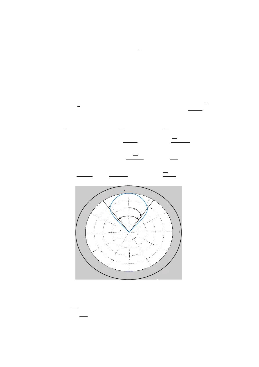
61
ﺎﺋﯿﺔــﺑﺮﮭﻜﻟا ﺔﺳﺪﻨﮭﻟا ﻢﺴﻗ ﻞــــﺻﻮﻤﻟا ﺔﻌﻣﺎﺟ
ﺎﻻتــﺼﺗﻻاو ﻚـــﯿﻧوﺮﺘﻜﻟﻻا عﺮـــــــــــــــﻓ
ﺎروديــﺒﻟا ﺪﻤﺤﻣ ﺪﯾﺆﻣ ناوﺮﻣ ﺐﻟﺎﻄﻟا داﺪﻋا
Ex:-
The power radiated by a lossless antenna is 10 watts. The radiation intensity
of the antenna is given by:
(
, ) =
0 ≤
≤
2
0 ≤
≤ 2
1-Find the maximum power density at a distance of 1000m.
2-Find the directive gain.
3-Plot the field pattern.
4-Find the HPBW.
The solution:-
=
∫ ∫ ( , )
Ω Ω
=
1-
10
=
∫
2
0
2
0
⟹
10
=
−
(2 )
4
4
0
2
10
=
−
2
(0 − 1)
⟹
=
20
⟹
( , ) =
20
(
, ) =
⟹
=
(
,
)
2
⟹
=
20
3
(1000)
2
maximum power density
=
20
(1000)
2
=
6.37
w
m
2
2- (
, )
=
4
,
=
4
3
10
⟹
=
4
20
(1)
10
= 8
3-
( , )
=
3
4-
0.5(
)
=
( , )
0.5(1)
=
3
ℎ
= √
0.5
=
√
0.5
=
37.5
HPBW
=
2|0 −
ℎ
|
HPBW
=
2|0 − 37.5 |
HPBW
=
75
0
0
0
30
150
60
120
90
180
210
240
270
330
300
37.5º
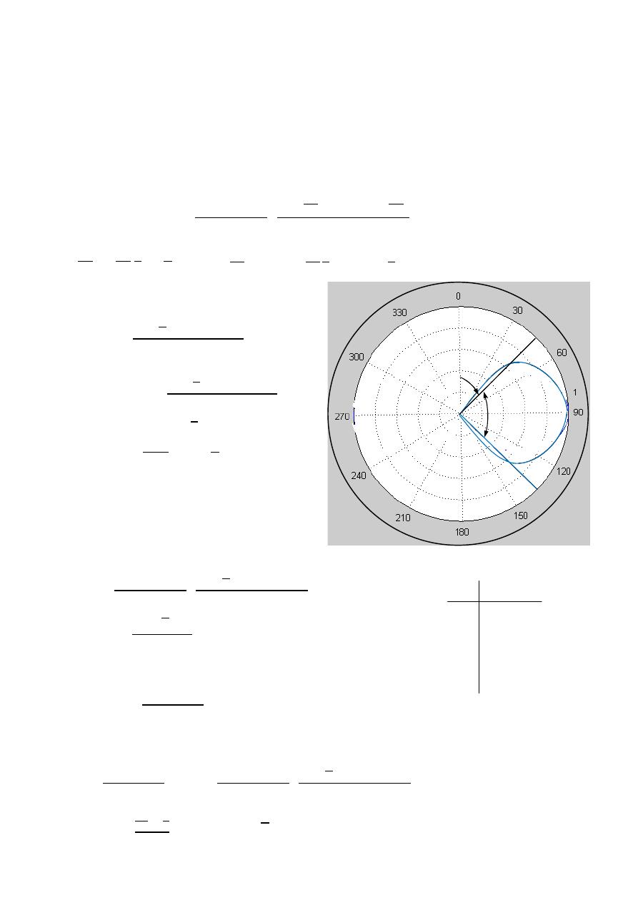
62
ﺎﺋﯿﺔــﺑﺮﮭﻜﻟا ﺔﺳﺪﻨﮭﻟا ﻢﺴﻗ ﻞــــﺻﻮﻤﻟا ﺔﻌﻣﺎﺟ
ﺎﻻتــﺼﺗﻻاو ﻚـــﯿﻧوﺮﺘﻜﻟﻻا عﺮـــــــــــــــﻓ
ﺎروديــﺒﻟا ﺪﻤﺤﻣ ﺪﯾﺆﻣ ناوﺮﻣ ﺐﻟﺎﻄﻟا داﺪﻋا
Ex:-
A
λ/4 dipole is fed with a current of 2A (rms).
1-Plot the field pattern of the dipole , and the estimate the HPBW.
2-Calculate the electric field strength at a distance of 800 Km in the plane
of maximum radiation.
3-If a dipole of length 0.075
λ is to produce the same electric field as that of
The
λ/4 dipole , find the current fed to this dipole.(assume maximum radiation)
The solution:-
=
60
−
2
−
2
=
=
,
(
2
)
=
cos(
2
2 4
)
=
(
4
)
=
0.707
1- HPBW
(
, )
=
4
−0.707
0.707(
)
=
( , )
0.707(0.293)
=
4
−0.707
0.207
ℎ
=
4
− 0.707
=
1
0.207
− 0.707
=
46.5
HPBW
=
2(90 −
ℎ
)
HPBW
=
2(90 − 46.5
)
HPBW
=
87
2-
⃗
=
60
−
4
−0.707
⃗
| ( , )|
|
| =
60
√
2×2
800000
(0.293)
=
62 V/m
3-
Infinitesimal (
≤ /50) ⟹ 0.075 λ
=
ℓ
−
4
Finite Length dipole (
> /10) ⟹ λ/4
=
ℓ
−
4
=
60
−
4
−0.707
(
120
)
2
4
4
(
1
) =
60 2
√
2
(
0.293
)
⟹
=
1.055
A
0 0
30° 0.14
45° 0.2018
60° 0.25
90° 0.293
45º
46.5º

63
ﺎﺋﯿﺔــﺑﺮﮭﻜﻟا ﺔﺳﺪﻨﮭﻟا ﻢﺴﻗ ﻞــــﺻﻮﻤﻟا ﺔﻌﻣﺎﺟ
ﺎﻻتــﺼﺗﻻاو ﻚـــﯿﻧوﺮﺘﻜﻟﻻا عﺮـــــــــــــــﻓ
ﺎروديــﺒﻟا ﺪﻤﺤﻣ ﺪﯾﺆﻣ ناوﺮﻣ ﺐﻟﺎﻄﻟا داﺪﻋا
Ex:-
For a dipole of 2.5m long (placed along the z-axis)operating at 120MHz
the amplitude of the electric field at 10 Km in the direction of maximum
radiation is 10 mV/m. if the directivity of the antenna is 1.7 , determine:
1- The transmitted power needed for reception.
2- The amplitude of the electric field at (2 Km , 30° , 90°).
3- HPBW.
The solution:-
=
60
−
2
−
2
| ( , )|
=
c
F
=
3×10
8
120×10
6
=
2.5m
,
=
.
.
⟹
=
1-
2
=
cos
2
2
=
( )
=
−1
⃗ =
60
−
(
)
+1
⃗
|
| =
60
10×10
3
(
2
)
⟹
10 × 10
−3
=
120
10×10
3
⟹
= 0.833A
W⃗
=
1
2
⃗
⊗
⃗
,
=
W⃗
=
1
2
60
−
+1
⃗
⊗
− 60
+1
⃗
W⃗
=
1
2
60
2
+1 2
⃗
=
4
+1 2
2
+1 2
0
[
(
)
+1
]
2
=
4
(2)
2
2 (
1.7
)
⟹
[
(
)
+1
]
2
=
4.7
=
W
⃗ . ⃗
⃗
=
⃗
=
1
2
60
2
+1 2
⃗
0
⃗
2
0
=
60
+1
2
=
60
0.833
√
2
4.7
=
200
6.774
=
166 W
2-
|
| =
60(0.833)
2000
(
30
)
+1
30
=
4.36m V/m
*
0 0
30° 0.174
45° 0.5572
60° 1.1547
90° 2
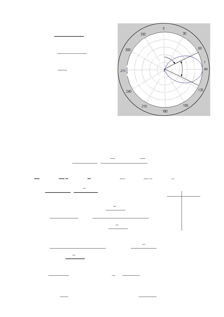
64
ﺎﺋﯿﺔــﺑﺮﮭﻜﻟا ﺔﺳﺪﻨﮭﻟا ﻢﺴﻗ ﻞــــﺻﻮﻤﻟا ﺔﻌﻣﺎﺟ
ﺎﻻتــﺼﺗﻻاو ﻚـــﯿﻧوﺮﺘﻜﻟﻻا عﺮـــــــــــــــﻓ
ﺎروديــﺒﻟا ﺪﻤﺤﻣ ﺪﯾﺆﻣ ناوﺮﻣ ﺐﻟﺎﻄﻟا داﺪﻋا
3- HPBW
(
, )
=
+1
0.707(
)
=
( , )
0.707(2)
=
+1
1.414
ℎ
=
(
) + 1
=
−1
1
1.414
[
(
)
+ 1
]
=
66.08
HPBW
=
2(90 −
ℎ
)
HPBW
=
2(90 − 66
)
HPBW
=
48
Ex:-
A
λ/2 dipole
situated with its center at the origin radiates a power of 600W
at a frequency of 300 MHz. a second
λ/2 dipole is placed at 1Km away from
the transmitting antenna in the direction of maximum radiation. assuming
the efficiency of the dipole is 90% , find the received power at the terminal
of the second (receiving) dipole.
The solution:-
=
60
−
2
−
2
=
=
,
(
2
)
=
cos(
2
2 2
)
=
(
2
)
= 0
⃗ =
60
−
2
⃗
( , )
=
4
,
,
Ω
=
4
2
2
2
2
2
0
=
4
(1)
2
2
2
2
0
,
2
2
=
1.218
=
4
1
2
(1.218)
=
1.642 ,
= =
3×10
8
300×10
6
=
1m
=
=
0.90 × 1.64
=
1.477 ,
=
=
1.476 the same dipole
=
=
600 × 1.477 × 1.477 ×
×
=
8.3
W
0 0
30° 0.417
45° 0.627
60° 0.816
90° 1
45º
66º
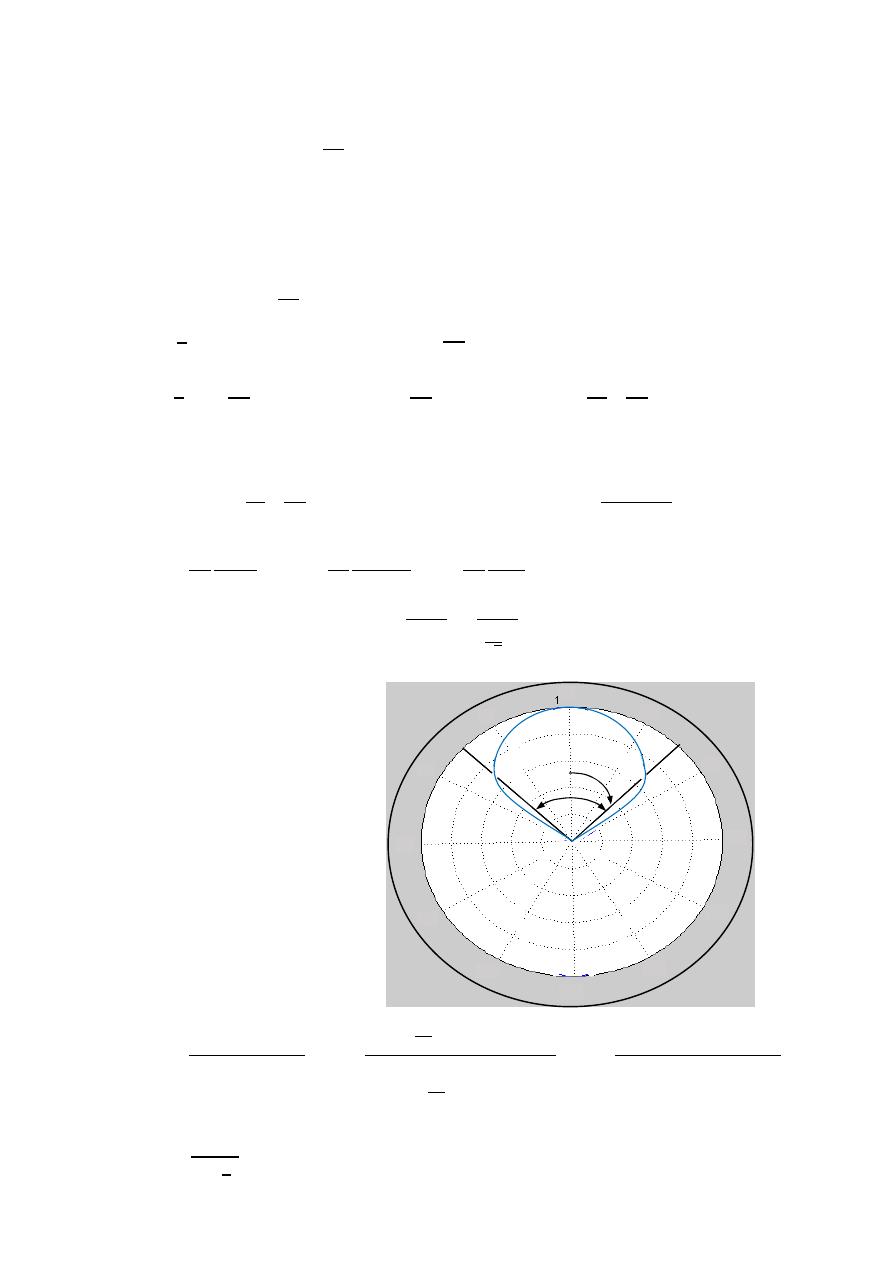
65
ﺎﺋﯿﺔــﺑﺮﮭﻜﻟا ﺔﺳﺪﻨﮭﻟا ﻢﺴﻗ ﻞــــﺻﻮﻤﻟا ﺔﻌﻣﺎﺟ
ﺎﻻتــﺼﺗﻻاو ﻚـــﯿﻧوﺮﺘﻜﻟﻻا عﺮـــــــــــــــﻓ
ﺎروديــﺒﻟا ﺪﻤﺤﻣ ﺪﯾﺆﻣ ناوﺮﻣ ﺐﻟﺎﻄﻟا داﺪﻋا
Ex:-
A transmitting antenna located at the origin has the far-electric field
⃗
=
10
−
⃗
V/m
If
= 1A , determine :
1- The radiated power .
2- The radiation resistance of the antenna.
3- HPBW, and directivity of the antenna.
The solution:-
⃗ =
10
−
⃗
1-
W⃗
=
1
2
⃗
⊗
⃗
,
=
W⃗
=
1
2
10
⃗
⊗
10
⃗
=
1
2
10 2
⃗
=
W
⃗ . ⃗
⃗
=
⃗
=
1
2
10 2
⃗
0
⃗
2
0
=
100(2 )
2(120 )
∫
0
= −
10
12
3
3
0
= −
10
12
(−1−1)
3
= −
10
12
(−2)
3
=
0.555W
2-
=
⟹
=
2
=
0.555
1
2
2
=
1.11Ω
3-
(
, )
=
0.707(
)
=
( , )
0.707(1)
=
ℎ
=
0.707
=
0.707
=
45
HPBW
=
2|0 −
ℎ
|
HPBW
=
2|0 − 45 |
HPBW
=
90
4-
=
4
(
,
)|
∫ ∫ (
,
)
Ω
=
4
2
2
|
|
2
2
2
|
|
2
0
2
0
=
4
(1)
2
2
2
0
=
4
(1)
2
2
2
3
= 3
*
0
30
150
300
60
120
90
330
270
180
210
240
45º

66
ﺎﺋﯿﺔــﺑﺮﮭﻜﻟا ﺔﺳﺪﻨﮭﻟا ﻢﺴﻗ ﻞــــﺻﻮﻤﻟا ﺔﻌﻣﺎﺟ
ﺎﻻتــﺼﺗﻻاو ﻚـــﯿﻧوﺮﺘﻜﻟﻻا عﺮـــــــــــــــﻓ
ﺎروديــﺒﻟا ﺪﻤﺤﻣ ﺪﯾﺆﻣ ناوﺮﻣ ﺐﻟﺎﻄﻟا داﺪﻋا
Ex:-
The electric field intensity in the far region of an antenna is given by:
⃗ =
100
.
⃗
2
1/2
0
0≤ ≤ 0≤ ≤ /2
If
= 1A , determine :
1- The radiation resistance.
2- Directivity.
3- HPBW in the x-y
(θ = 90) plane.
4- HPBW in the x-z
(ϕ = 90) plane.
If a dipole of 2.5m length is to produce the same electric field as that of
The above antenna, find the current fed to this dipole(assume maximum radiation)
The solution:-
⃗ =
100
.
(
2
)
1/2
⃗
1-
W⃗
=
1
2
⃗
⊗
⃗
,
=
W⃗
=
1
2
100
− 0.2
(
2
)
/
⃗
⊗
100
0.2
(
2
)
/
⃗
W⃗
=
1
2
100
2
(
) ⃗
=
W
⃗ . ⃗
⃗
=
⃗
=
1
2
100
2
(
) ⃗
0
⃗
2
0
=
100
2
2
0
2
0
=
100
2
2
∫
0
2
0
=
100 × 2
2
2×120
4
2
=
32.7
2
=
32.7Ω
2-
=
4
,
,
Ω
=
4
2
2
2
0
0
=
4
1
2
4
2
=
32
=
10.186
3-
= (
2
)
1/2
at
=
90°
= (
90
2
)
1/2
⟹
= (
2
)
1/2
=
0.707(1)
=
⟹
=
(0.707)
⟹
=
45°
HPBW
=
2|0 −
ℎ
|
HPBW
=
2|0 − 45°|
=
90°
everywhere
*

67
ﺎﺋﯿﺔــﺑﺮﮭﻜﻟا ﺔﺳﺪﻨﮭﻟا ﻢﺴﻗ ﻞــــﺻﻮﻤﻟا ﺔﻌﻣﺎﺟ
ﺎﻻتــﺼﺗﻻاو ﻚـــﯿﻧوﺮﺘﻜﻟﻻا عﺮـــــــــــــــﻓ
ﺎروديــﺒﻟا ﺪﻤﺤﻣ ﺪﯾﺆﻣ ناوﺮﻣ ﺐﻟﺎﻄﻟا داﺪﻋا
4-
= (
2
)
at
=
0°
= (
2
0
)
⟹
=
(
1/2
)
=
⟹
0.707
(
1
) =
=
0.5
⟹
=
(0.5)
⟹
=
30°
HPBW
=
2|90° −
ℎ
|
HPBW
=
2|90° − 30°|
=
120°
=
60
−
2
−
2
| ( , )|
.
⟺
=
0.2
=
0.2
⟹
=
.
=
10m
⟹
=
2.5
10
⟹
=
1
4
=
=
,
(
2
)
=
cos(
2
2 4
)
=
(
4
)
=
0.707
⃗ =
60
−
4
−0.707
⃗
=
− 0.2
(
2
)
1/2
=
−
4
.
100
(1)
/
=
60
(
0.293
)
100 × 1
=
17.58
(
0.293
)
=
100
17.58
=
5.688A
Ex:-
Transmitting and receiving antenna operating at 1GHz with gains 20 and
15 dB respectively are separated by a distance of 1Km . find the maximum
Power delivered to the load when the total power is 150W.
The solution:-
=
20
=
10
20
20
=
10
,
=
15
=
10
15
20
=
5.6
=
=
×
=
0.3m
=
=
150 × 10 × 5.6 ×
.
×
=
4.8
W
0 0
30° 0.14
45° 0.2018
60° 0.25
90° 0.293
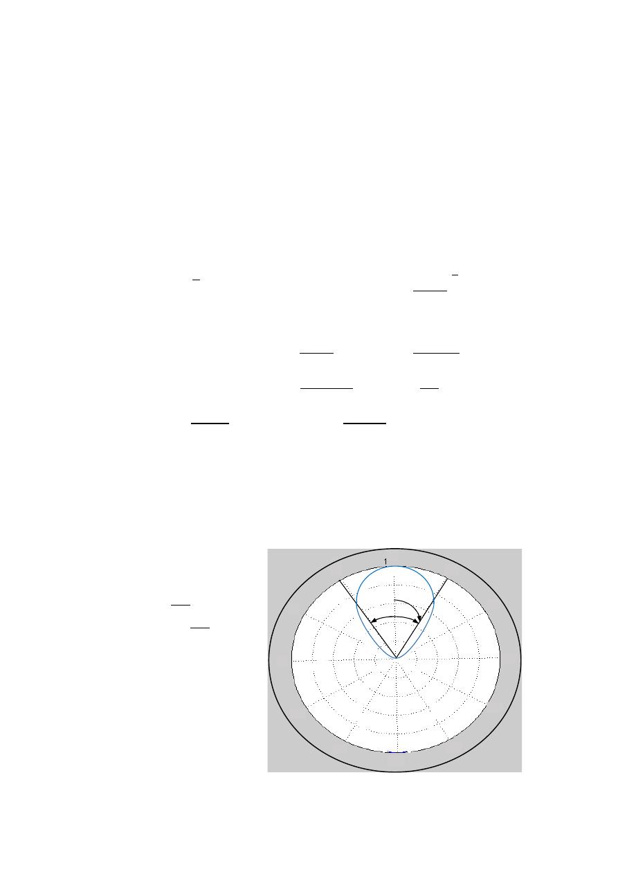
68
ﺎﺋﯿﺔــﺑﺮﮭﻜﻟا ﺔﺳﺪﻨﮭﻟا ﻢﺴﻗ ﻞــــﺻﻮﻤﻟا ﺔﻌﻣﺎﺟ
ﺎﻻتــﺼﺗﻻاو ﻚـــﯿﻧوﺮﺘﻜﻟﻻا عﺮـــــــــــــــﻓ
ﺎروديــﺒﻟا ﺪﻤﺤﻣ ﺪﯾﺆﻣ ناوﺮﻣ ﺐﻟﺎﻄﻟا داﺪﻋا
Ex:-
The radiation intensity of a lossless antenna is given by:
(
, )
=
10
4
0
0≤ ≤90
90 ≤ ≤180
Determine:
1- The radiated power.
2- The average power density at (1Km , 30° , 60°).
3- Directivity.
4- Gain at (30° , 60°).
5- HPBW.
The solution:-
=
∫ ∫ ( , )
Ω Ω
=
1-
=
∫ 10
2
0
0
=
−10(2 )
5
5
0
2
= −
4 (0 − 1
=
4
watt
2- (
, ) =
⟹
=
(
,
)
2
⟹
=
10
4
(1000)
2
maximum power density
=
10
4
30
(1000)
2
=
5.66
w
m
2
3- (
, )
=
4
,
⟹
( , )
=
4
10
4
4
(
, )
=
10
⟹
=
10(1)
=
10
4- ( , )
=
( , )
lossless
=
100%
(
, )
=
( , )
⟹
( , )
=
10
( , )
=
10
30
=
5.66m
5-
( , )
=
4
0.5(
)
=
( , )
0.5(1)
=
4
ℎ
= √
0.5
=
√
0.5
=
32.76
HPBW
=
2|0 −
ℎ
|
HPBW
=
2|0 − 32.76 |
HPBW
=
65.5
0
0
0
30
150
60
120
90
180
210
240
270
330
300
32.7º
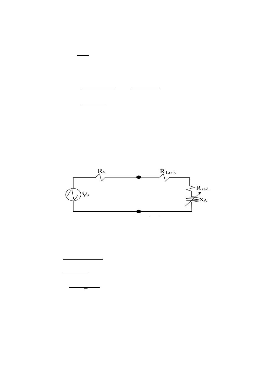
69
ﺎﺋﯿﺔــﺑﺮﮭﻜﻟا ﺔﺳﺪﻨﮭﻟا ﻢﺴﻗ ﻞــــﺻﻮﻤﻟا ﺔﻌﻣﺎﺟ
ﺎﻻتــﺼﺗﻻاو ﻚـــﯿﻧوﺮﺘﻜﻟﻻا عﺮـــــــــــــــﻓ
ﺎروديــﺒﻟا ﺪﻤﺤﻣ ﺪﯾﺆﻣ ناوﺮﻣ ﺐﻟﺎﻄﻟا داﺪﻋا
Ex:-
A) The maximum radiation intensity of a 90% efficiency antenna is 200mW/unit
solid angle. find the directivity and gain when the point power is 40 mW.
The solution:-
=
=
×
=
0.90 × 40 × 10
=
113
m
=
4
,
,
Ω
=
4
,
=
4
200×10
−3
113×10
−3
=
22.22
=
=
0.90 × 22.22
=
20
B) A
λ/2 dipole with loss resistance of 1Ω is connected to a generator whose
internal resistance is 50
Ω. assuming that the peak voltage of the generator
is 2V. find the power radiated by the antenna.
The solution:-
=
73Ω for λ/2
=
1Ω
=
=
50Ω
=
2V
=
+
+
=
2
50+73+1
=
16.13 mA
=
16.13×10
−3
2
=
11.4 mA
=
=
(11.4 × 10 ) × 73
=
9.48 mW
neglect
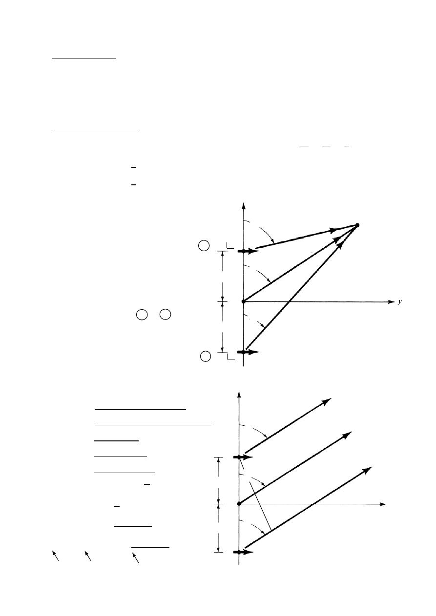
70
ﺎﺋﯿﺔــﺑﺮﮭﻜﻟا ﺔﺳﺪﻨﮭﻟا ﻢﺴﻗ ﻞــــﺻﻮﻤﻟا ﺔﻌﻣﺎﺟ
ﺎﻻتــﺼﺗﻻاو ﻚـــﯿﻧوﺮﺘﻜﻟﻻا عﺮـــــــــــــــﻓ
ﺎروديــﺒﻟا ﺪﻤﺤﻣ ﺪﯾﺆﻣ ناوﺮﻣ ﺐﻟﺎﻄﻟا داﺪﻋا
Theory
Array
In many application it is necessary to design antennas with very direction
Characteristic (very high gain) to meet the demand of long distance communication.
Antenna array is used when greater directivity is required.
Two element array
Assume P is remote from the antenna system for amplitude
1
1
=
1
2
=
1
For phase
1
=
−
2
2
=
+
2
1
&
2
≫
The phase difference between
radiation from the two elements
will be .
=
+
: is the path difference.
:
is the phase angle between
& .
assume the element & are
isotropic .
they have constant electric field and
equal to
.
⃗ = ⃗ + ⃗
=
+
=
(1 +
+
)
| | =
(1 +
) +
| | =
1
+
2
+
+
| | =
2
+
2
| | =
2(1
+
)
| | =
2 × 2
2
| | = 2
2
| | = 2
+
2
| | = (
) 2
+
2
Two element array
Far-field observations
z
y
d/2
d/2
d/2
d/2
I =I
1
0
I =I
2
∝
d
r
r
2
r
r
2
c
o
s
θ
1
2
2
1
2
Total for
electric field
Element
Factor
Array
Factor (AF)
r
1
1
1
r
z
P
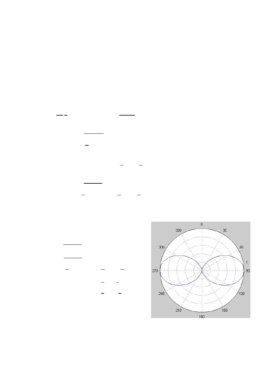
71
ﺎﺋﯿﺔــﺑﺮﮭﻜﻟا ﺔﺳﺪﻨﮭﻟا ﻢﺴﻗ ﻞــــﺻﻮﻤﻟا ﺔﻌﻣﺎﺟ
ﺎﻻتــﺼﺗﻻاو ﻚـــﯿﻧوﺮﺘﻜﻟﻻا عﺮـــــــــــــــﻓ
ﺎروديــﺒﻟا ﺪﻤﺤﻣ ﺪﯾﺆﻣ ناوﺮﻣ ﺐﻟﺎﻄﻟا داﺪﻋا
Ex:-
Plot the normalized radiation pattern of two element isotropic array for
The following cases:
1-
= /2 , = 0
2-
= /2 , =
3-
= /4 , = /2
4-
= , = 0
1-
= /2 , = 0
=
2
2
=
,
=
2
A- max value
2
=
1
=
0 , ± , ± 2 , …
=
0 , ± 2 , ± 4
=
±
2
, ± 3
2
B- nulls
2
=
0
=
± , ± 3 , …
=
±1 , ± 3 ,
=
0 , ±
C- HPBW
ℎ
2
=
0.707(max)
ℎ
2
=
0.707(1)
ℎ
=
± , ± 3 , …
=
±
1
2
, ±
3
2
=
±
3
, ±2
3
HPBW
=
2|90 − 60 |
HPBW
=
120
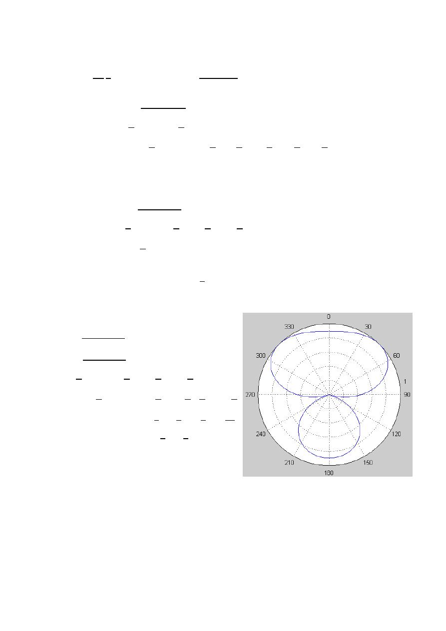
72
ﺎﺋﯿﺔــﺑﺮﮭﻜﻟا ﺔﺳﺪﻨﮭﻟا ﻢﺴﻗ ﻞــــﺻﻮﻤﻟا ﺔﻌﻣﺎﺟ
ﺎﻻتــﺼﺗﻻاو ﻚـــﯿﻧوﺮﺘﻜﻟﻻا عﺮـــــــــــــــﻓ
ﺎروديــﺒﻟا ﺪﻤﺤﻣ ﺪﯾﺆﻣ ناوﺮﻣ ﺐﻟﺎﻄﻟا داﺪﻋا
2-
= /2 , =
=
2
2
=
,
=
+
2
A- max value
+
2
=
1
+ =
0 , ± , ± 2 , …
=
− , + , −3 , +3 , −5
=
−1 , + 1, −3, +3, −5
=
0, ±
B- nulls
+
2
=
0
+ =
± , ± 3 , …
=
0 , − , + , −2
=
0 , −2 , +2 , −4
=
±
2
C- HPBW
ℎ
+
2
=
0.707(max)
ℎ
+
2
=
0.707(1)
ℎ
+ =
± , ± 3 , …
ℎ
=
− , −3 ,
, −
5
=
−
1
2
, −
6
4
, +
1
2
, −
10
4
=
±2
3
,
±
3
HPBW
=
2 × 60
HPBW
=
120
or
HPBW
=
2|180 − 120 |
HPBW
=
120
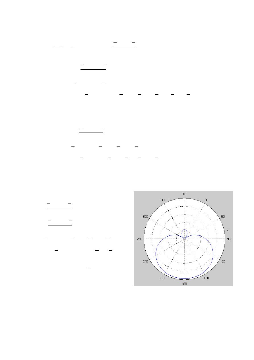
73
ﺎﺋﯿﺔــﺑﺮﮭﻜﻟا ﺔﺳﺪﻨﮭﻟا ﻢﺴﻗ ﻞــــﺻﻮﻤﻟا ﺔﻌﻣﺎﺟ
ﺎﻻتــﺼﺗﻻاو ﻚـــﯿﻧوﺮﺘﻜﻟﻻا عﺮـــــــــــــــﻓ
ﺎروديــﺒﻟا ﺪﻤﺤﻣ ﺪﯾﺆﻣ ناوﺮﻣ ﺐﻟﺎﻄﻟا داﺪﻋا
3-
= /4 , = /2
=
2
4
=
2
,
=
2
+
2
2
A- max value
2
+
2
2
=
1
+ =
0 , ± , ± 2 , …
=
− , +3 , −5 , +7 , −9
=
−1 , + 3, −5, +7, −9
=
±
B- nulls
2
+
2
2
=
0
+ =
± , ± 3 , …
=
, −3 , 5 , −7
=
+1 , −3 , + 5, −7
=
0
C- HPBW
2
ℎ
+
2
2
=
0.707(max)
2
ℎ
+
2
2
=
0.707(1)
ℎ
+ =
± , ± 3 , …
ℎ
=
0 , − , +
, −
=
0 , −2 , + 2
, −
4
=
±
2
HPBW
=
2|180 − 90 |
HPBW
=
180
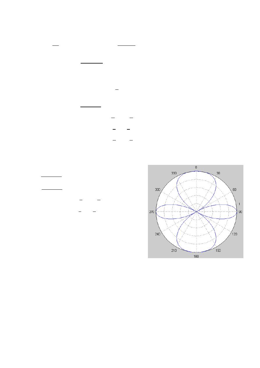
74
ﺎﺋﯿﺔــﺑﺮﮭﻜﻟا ﺔﺳﺪﻨﮭﻟا ﻢﺴﻗ ﻞــــﺻﻮﻤﻟا ﺔﻌﻣﺎﺟ
ﺎﻻتــﺼﺗﻻاو ﻚـــﯿﻧوﺮﺘﻜﻟﻻا عﺮـــــــــــــــﻓ
ﺎروديــﺒﻟا ﺪﻤﺤﻣ ﺪﯾﺆﻣ ناوﺮﻣ ﺐﻟﺎﻄﻟا داﺪﻋا
4-
= , = 0
=
2
=
2 ,
=
2
2
A- max value
2
2
=
1
=
0 , ± , ± 2 , …
=
0 , ± 1, ± 2
=
±
2
, 0,
B- nulls
2
2
=
0
=
±
2
, ± 3
2
, …
=
±
1
2
, ±
3
2
,
=
±
3
, ±2
3
C- HPBW
2
ℎ
2
=
0.707(max)
2
ℎ
2
=
0.707(1)
=
±
4
, ± 3
4
, …
=
±
1
4
, ±
3
4
=
75.5 , 104.5 , 41.4 , 138.59
HPBW
=
2|90 − 75.5 |
HPBW
=
29
or
HPBW
=
2|90 − 104.5 |
HPBW
=
29
or
HPBW
=
2|0 − 41.4 |
HPBW
=
82.8
or
HPBW
=
2|180 − 138.59 |
HPBW
=
82.8
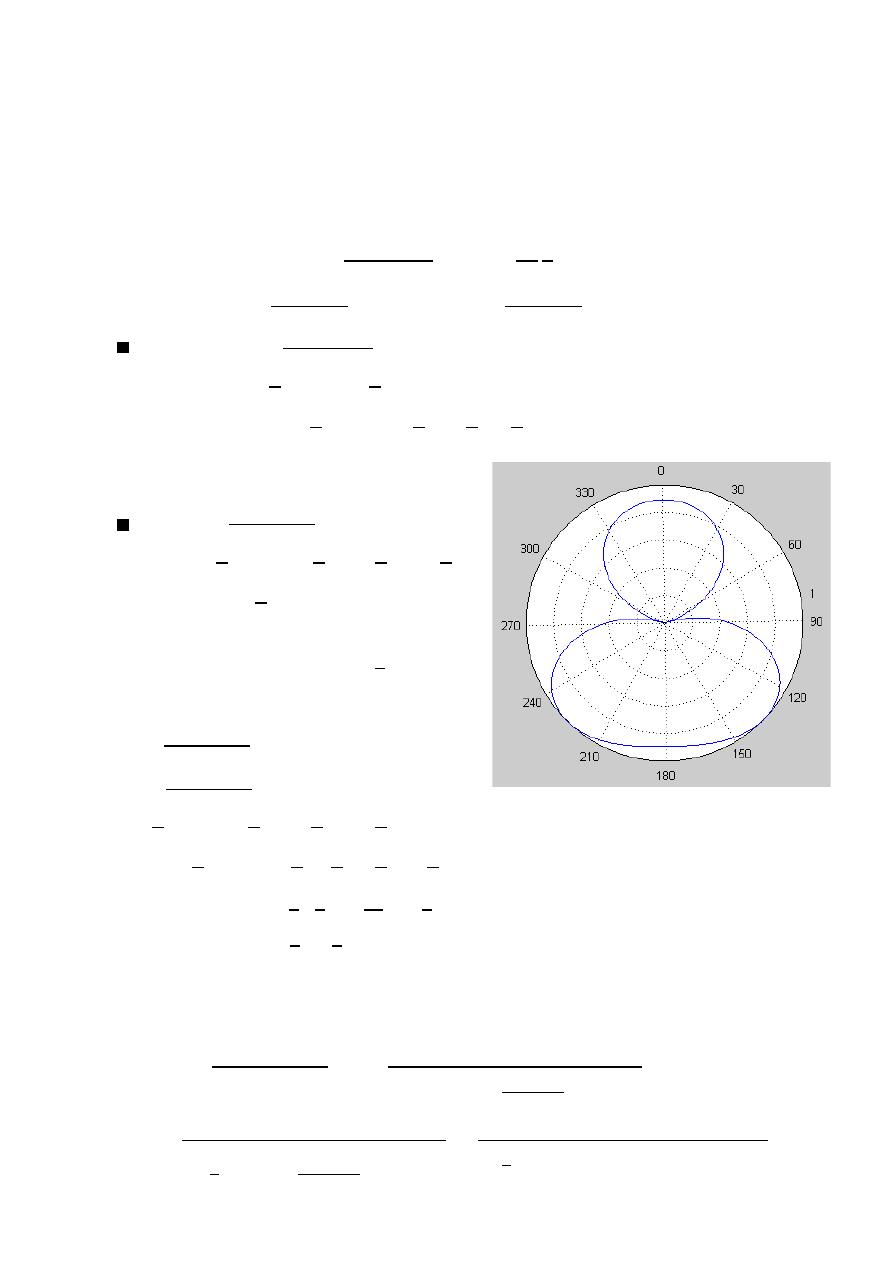
75
ﺎﺋﯿﺔــﺑﺮﮭﻜﻟا ﺔﺳﺪﻨﮭﻟا ﻢﺴﻗ ﻞــــﺻﻮﻤﻟا ﺔﻌﻣﺎﺟ
ﺎﻻتــﺼﺗﻻاو ﻚـــﯿﻧوﺮﺘﻜﻟﻻا عﺮـــــــــــــــﻓ
ﺎروديــﺒﻟا ﺪﻤﺤﻣ ﺪﯾﺆﻣ ناوﺮﻣ ﺐﻟﺎﻄﻟا داﺪﻋا
Ex
:- Two element isotropic array placed along the z-axis spacing is
= /2 ,
= − .
1- Find & plot the array factor.
2- Determine the half power beam width.
3-
Explain how to find directivity.
The solution:-
=
2
+
2
,
=
2
2
=
1-
=
2
−
2
⟹
=
−
2
max value
−
2
=
1
− =
0 , ± , …
=
, − , 3
=
1 , − 1
=
0 ,
nulls
−
2
=
0
− =
± , ± 3 , …
=
0 , , − , 2
=
0 , +2 , −2 , −4
=
±
2
2- HPBW
ℎ
−
2
=
0.707(max)
ℎ
−
2
=
0.707(1)
ℎ
− =
± , ± 3 , …
ℎ
=
,3 , 5
, −
=
1
2
,
6
4
, +
10
4
, −
1
2
=
3
, 2
3
HPBW
=
2 × 60 or HPBW
=
2|180 − 120 |
HPBW
=
120 HPBW
=
120
3-
=
4
(
,
)|
∫ ∫ (
,
)
Ω
=
4
(1)
2
(2 )
−
2
0
=
2
1
2
−
2
0
=
2
1
2
(
+
(
)
)
0
= 2
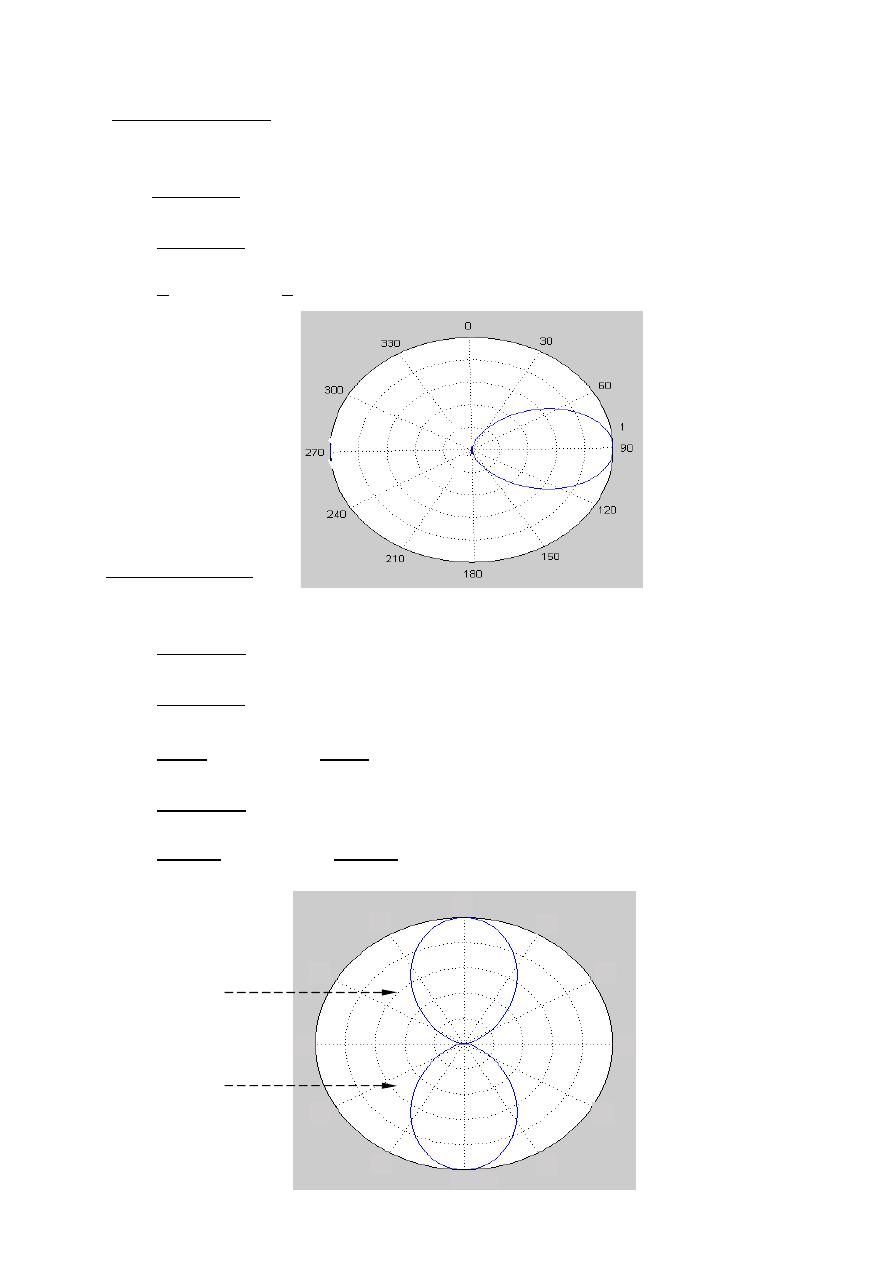
76
ﺎﺋﯿﺔــﺑﺮﮭﻜﻟا ﺔﺳﺪﻨﮭﻟا ﻢﺴﻗ ﻞــــﺻﻮﻤﻟا ﺔﻌﻣﺎﺟ
ﺎﻻتــﺼﺗﻻاو ﻚـــﯿﻧوﺮﺘﻜﻟﻻا عﺮـــــــــــــــﻓ
ﺎروديــﺒﻟا ﺪﻤﺤﻣ ﺪﯾﺆﻣ ناوﺮﻣ ﺐﻟﺎﻄﻟا داﺪﻋا
side Array
Broad
In this case the maximum radiation is directed normal to this axis of the array.
+
2
=
1
⟹
at
=
90
+
2
=
1
2
=
1
⟹
2
=
0
⟹
=
0
Fire Array
-
End
In this case the maximum radiation is along the axis of the elements.
+
2
=
1
⟹
at (
=
0 ,
=
180 )
+
2
=
1
+
2
=
1
⟹
+
2
=
0
⟹
+
=
0
⟹
=
−
+
2
=
1
−
+
2
=
1
⟹
−
+
2
=
0
⟹ −
+
=
0
⟹
=
+
=
±
=
−
=
+
0
30
60
90
120
150
180
240
210
270
330
300
or

77
ﺎﺋﯿﺔــﺑﺮﮭﻜﻟا ﺔﺳﺪﻨﮭﻟا ﻢﺴﻗ ﻞــــﺻﻮﻤﻟا ﺔﻌﻣﺎﺟ
ﺎﻻتــﺼﺗﻻاو ﻚـــﯿﻧوﺮﺘﻜﻟﻻا عﺮـــــــــــــــﻓ
ﺎروديــﺒﻟا ﺪﻤﺤﻣ ﺪﯾﺆﻣ ناوﺮﻣ ﺐﻟﺎﻄﻟا داﺪﻋا
Ex:-
Using the array factor for a two element broadside array with equal amplitude
Point source element, show that the directivity expression is:
=
2
1+
If
=
2 , plot the array factor , and then determine the HBPW.
The solution:-
=
+
2
,
broadside
∴
=
0
=
2
=
4
(
,
)|
∫ ∫ (
,
)
Ω
=
4
(1)
2
2
0
2
0
=
4
(1)
2
2
1
2
(
1+
2
2
)
0
=
2
1
2
(
1+
(
)
)
0
=
2
1
2
∫
0
+
∫
(
)
0
=
4
−
|
+ −
1
(
)
|
=
4
−
(
−
0
)
−
1
(
)
−
(
0
)
=
4
−
(
−1−1
)
−
1
(
−
)
−
(
)
=
4
−(−2)−
1
−
(
)
−
(
)
=
4
2−
1
−2
(
)
=
4
2+
2
(
)
=
4
2 1+
1
(
)
=
2
1+
=
2
1+
⟹
2 =
2
1+
2 =
2
+
⟹
2 =
2
+
⟹
+
=
2
2
+
=
=
−
=
0
=
where ≠ 0
=
2
=
=
2
, = 0
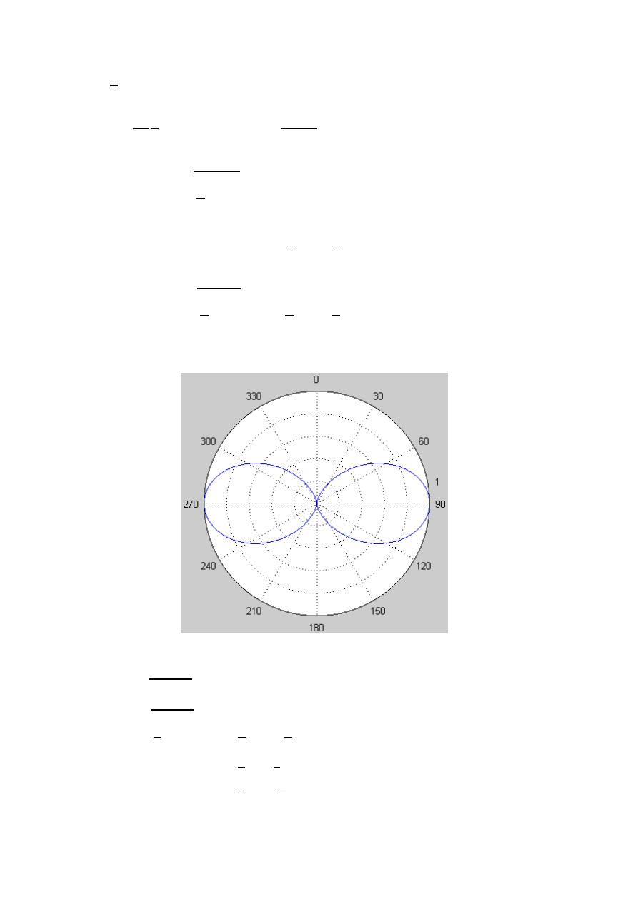
78
ﺎﺋﯿﺔــﺑﺮﮭﻜﻟا ﺔﺳﺪﻨﮭﻟا ﻢﺴﻗ ﻞــــﺻﻮﻤﻟا ﺔﻌﻣﺎﺟ
ﺎﻻتــﺼﺗﻻاو ﻚـــﯿﻧوﺮﺘﻜﻟﻻا عﺮـــــــــــــــﻓ
ﺎروديــﺒﻟا ﺪﻤﺤﻣ ﺪﯾﺆﻣ ناوﺮﻣ ﺐﻟﺎﻄﻟا داﺪﻋا
=
2
, = 0
=
2
2
=
,
=
2
max value
2
=
1
=
0 , ± , ± 2 , …
=
0 , ± 2 , ± 4
=
±
2
, ± 3
2
nulls
2
=
0
=
± , ± 3 , …
=
±1 , ± 3 ,
=
0 , ±
HPBW
ℎ
2
=
0.707(max)
ℎ
2
=
0.707(1)
ℎ
=
± , ± 3 , …
=
±
1
2
, ±
3
2
=
±
3
, ±2
3
HPBW
=
2|90 − 60 |
HPBW
=
120

79
ﺎﺋﯿﺔــﺑﺮﮭﻜﻟا ﺔﺳﺪﻨﮭﻟا ﻢﺴﻗ ﻞــــﺻﻮﻤﻟا ﺔﻌﻣﺎﺟ
ﺎﻻتــﺼﺗﻻاو ﻚـــﯿﻧوﺮﺘﻜﻟﻻا عﺮـــــــــــــــﻓ
ﺎروديــﺒﻟا ﺪﻤﺤﻣ ﺪﯾﺆﻣ ناوﺮﻣ ﺐﻟﺎﻄﻟا داﺪﻋا
Ex:-
show that the directivity expression for end-fire array is:
=
4
2+
2
The solution:-
=
+
2
,
end-fire
∴
=
−
or
=
+
=
+
2
=
4
(
,
)|
∫ ∫ (
,
)
Ω
=
4
(1)
2
+
2
0
2
0
=
4
(1)
2
2
1
2
(
1+
2
+
2
)
0
=
2
1
2
(
1+
(
+
)
)
0
=
2
1
2
∫
0
+
∫
(
+
)
0
=
4
−
|
+ −
1
(
+
)
|
=
4
−
(
−
0
)
−
1
(
+
)
−
(
0+
)
=
4
−
(
−1−1
)
−
1
(
−
+
)
−
(
+
)
=
4
−(−2)−
1
(
0
)
−
(
2
)
=
4
−(−2)−
1
0−
(
2
)
=
4
2+
1
(
2
)
=
4
2+
1
(
2
)
=
4
2+
2
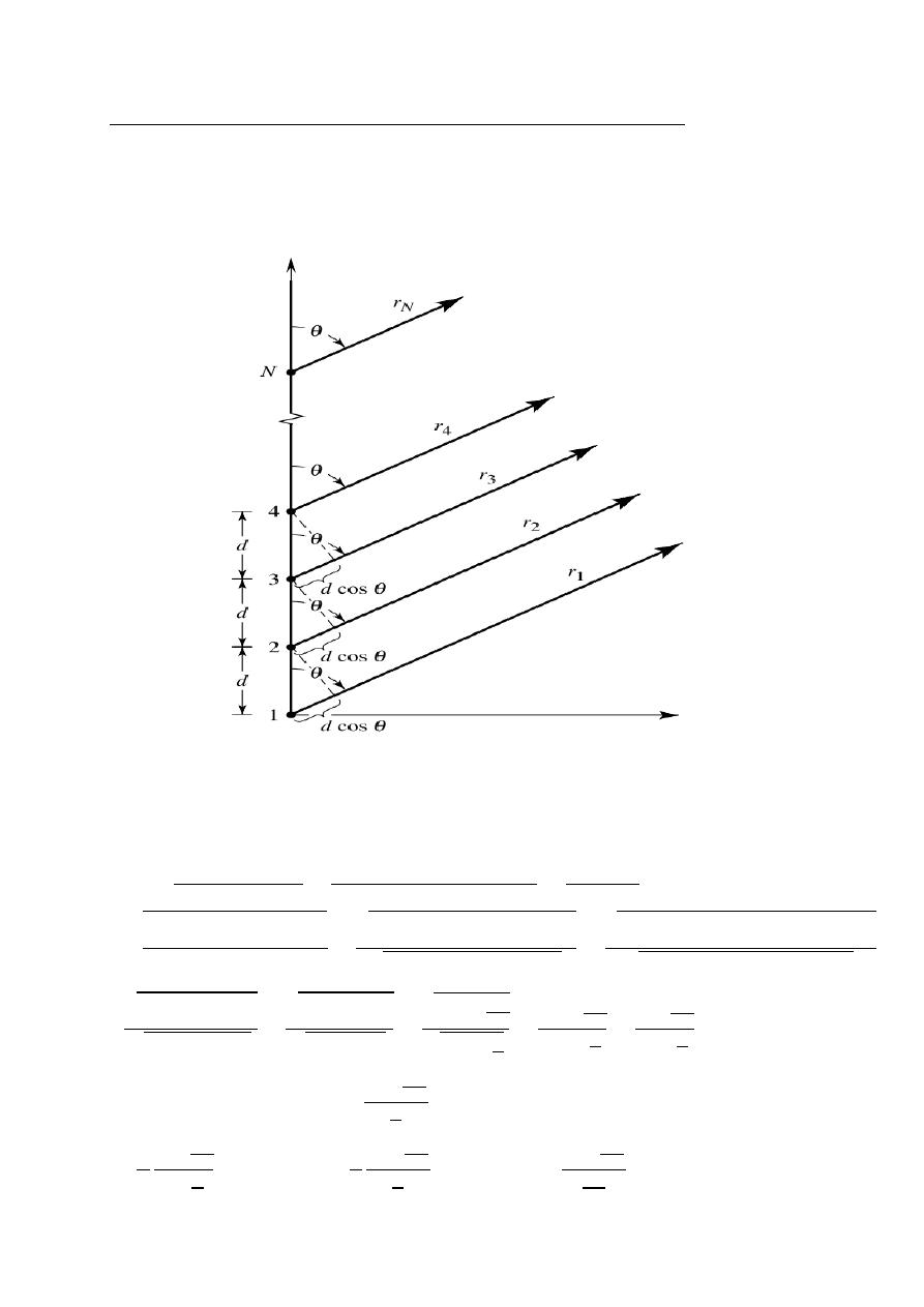
80
ﺎﺋﯿﺔــﺑﺮﮭﻜﻟا ﺔﺳﺪﻨﮭﻟا ﻢﺴﻗ ﻞــــﺻﻮﻤﻟا ﺔﻌﻣﺎﺟ
ﺎﻻتــﺼﺗﻻاو ﻚـــﯿﻧوﺮﺘﻜﻟﻻا عﺮـــــــــــــــﻓ
ﺎروديــﺒﻟا ﺪﻤﺤﻣ ﺪﯾﺆﻣ ناوﺮﻣ ﺐﻟﺎﻄﻟا داﺪﻋا
Uniform Amplitude And Spacing
Array
linear
Element
-
N
Assume all the element have identical Amplitude.
The progressive phase is
.
Assume all the elements are isotropic.
AF = 1 +
+
+ ∙∙∙∙∙∙ +
(
)
where
=
+
AF =
(
)
=
=
AF =
−
( +1)
1−
=
−
−
−
1−
=
1−
1−
AF =
(1−
)
2
+(
)
2
(1−
)
2
+(
)
2
=
(1−
)
2
+(
)
2
(1−
)
2
+(
)
2
=
1−2
+
2
+
2
1−2
+
2
+
2
AF =
1−2
+1
1−2
+1
=
2−2
2−2
=
4
2
2
4
2
2
=
2
2
2
2
=
2
2
For small value of
⟹
|
AF| =
2
2
AF =
1
2
2
⟹
AF ≃
1
2
2
⟹
AF =
2
2
Z
y
N
n
n=1
n=1
n=1
N
N

81
ﺎﺋﯿﺔــﺑﺮﮭﻜﻟا ﺔﺳﺪﻨﮭﻟا ﻢﺴﻗ ﻞــــﺻﻮﻤﻟا ﺔﻌﻣﺎﺟ
ﺎﻻتــﺼﺗﻻاو ﻚـــﯿﻧوﺮﺘﻜﻟﻻا عﺮـــــــــــــــﻓ
ﺎروديــﺒﻟا ﺪﻤﺤﻣ ﺪﯾﺆﻣ ناوﺮﻣ ﺐﻟﺎﻄﻟا داﺪﻋا
1- Principal maximum :
A principal maximum occurs when
= 0.
AF =
2
2
=
0
0
un defined
AF =
2
2
1
2
2
=
2
0
1
2
0
=
2
1
2
=
⟹
AF
= N
=
+
⟹
+
= 0
⟹
= −
2
= −
⟹
=
2
⟹
=
2
2- nulls :
AF =
2
2
⟹
2
2
= 0
⟹
2
= 0
= ±
where
≠ 0 ,
= 1 , 2 , 3 , 4 , …..
(
+
)
= ±
⟹
= − ±
2
=
2
− ±
⟹
=
−1
− ±
2
3- Secondary maximum :
2
= ±1
2
= ±
2 +1
2
where
≠ 0 , = 1 , 2 , 3 , 4 , …..
=
2
− ±
2 +1
The maximum of the first secondary lobe (miner lobe) occur when
= 1
= ±
AF =
2
2
=
±
1
3
2
=
±
2
3
AF =
2
3
AF =
2
3
=
2
3
=
0.212
AF = 20 log (0.212) = −13.47

82
ﺎﺋﯿﺔــﺑﺮﮭﻜﻟا ﺔﺳﺪﻨﮭﻟا ﻢﺴﻗ ﻞــــﺻﻮﻤﻟا ﺔﻌﻣﺎﺟ
ﺎﻻتــﺼﺗﻻاو ﻚـــﯿﻧوﺮﺘﻜﻟﻻا عﺮـــــــــــــــﻓ
ﺎروديــﺒﻟا ﺪﻤﺤﻣ ﺪﯾﺆﻣ ناوﺮﻣ ﺐﻟﺎﻄﻟا داﺪﻋا
4- HPBW
AF =
2
2
⟹
0.707(
) =
2
2
0.707( ) =
2
2
⟹
0.707 =
2
2
⟹
0.707 =
∴
2
= ±1.391
(
ℎ
+
)
= ±1.391
⟹
ℎ
= − ±
.
2
ℎ
= − ±
.
⟹
=
2
− ±
2.782
=
2
− ±
2.782
HPBW
= 2|
−
|
Ex:-
Derive an expression for the HPBW for the following cases:
1- broadside case.
2- end-fire case.
The solution:-
1- broadside case
⟹
= 0 ,
= 90
=
2
− ±
2.782
=
2
±
2.782
=
±
1.391
HPBW
= 2|
−
|
HPBW
= 2 90 −
±
1.391
2- end-fire case
⟹
= ±
,
= 0
=
2
− ±
2.782
=
2
±
2.782
⟹
=
2
2
±
2.782
=
1 −
1.391
HPBW
= 2|
−
|
⟹
HPBW
= 2|0 −
|
HPBW
= 2
1 −
1.391
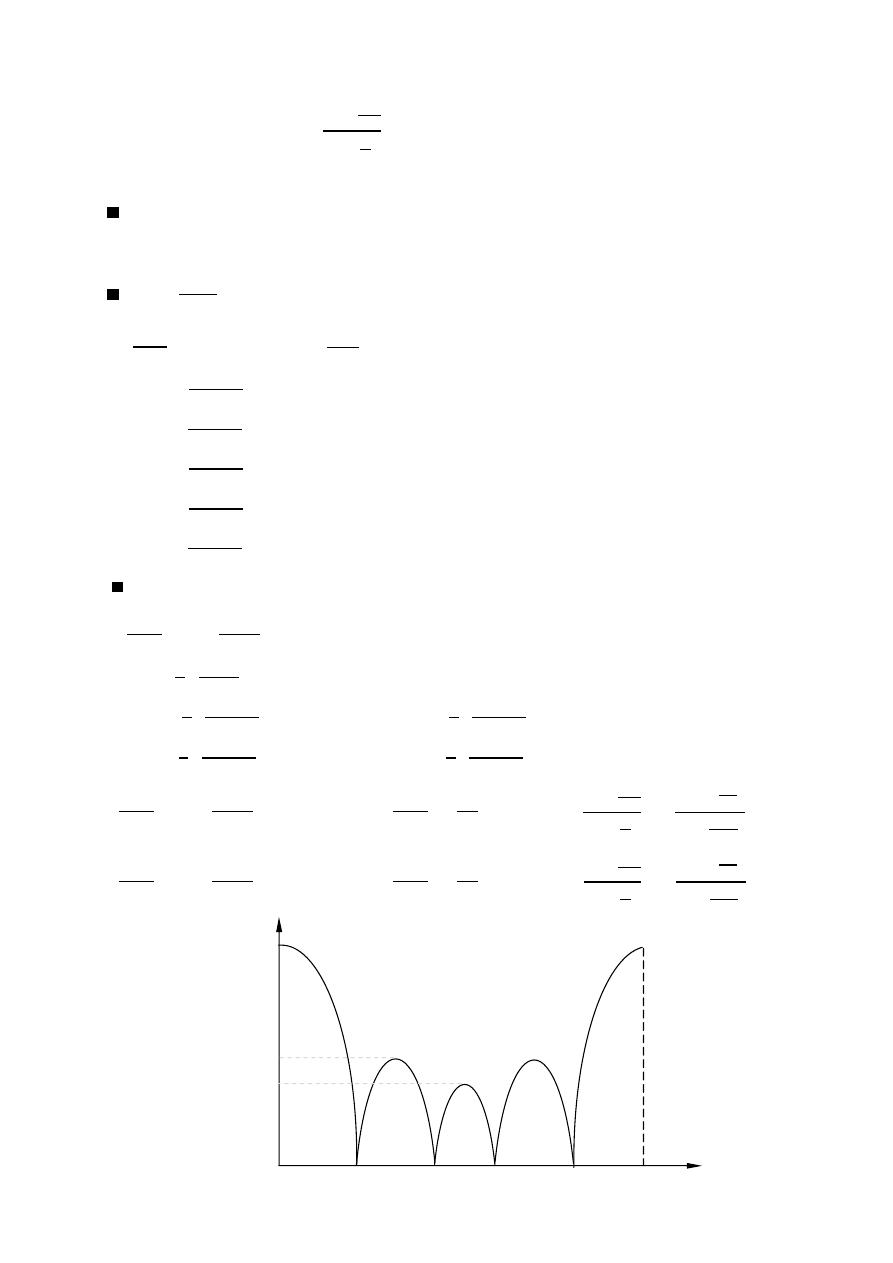
83
ﺎﺋﯿﺔــﺑﺮﮭﻜﻟا ﺔﺳﺪﻨﮭﻟا ﻢﺴﻗ ﻞــــﺻﻮﻤﻟا ﺔﻌﻣﺎﺟ
ﺎﻻتــﺼﺗﻻاو ﻚـــﯿﻧوﺮﺘﻜﻟﻻا عﺮـــــــــــــــﻓ
ﺎروديــﺒﻟا ﺪﻤﺤﻣ ﺪﯾﺆﻣ ناوﺮﻣ ﺐﻟﺎﻄﻟا داﺪﻋا
Ex:-
plot the expression
2
2
with for N = 5
The solution:- N = 5
Principal maximum N = 5 ,
= 0
AF
=
= 5
nulls
=
±
= 1 , 2 , 3 , 4 , 5
=
⟹
=
2
5
=
2×1×
5
= 72
=
2×2×
5
= 144
=
2×3×
5
= 216
=
2×4×
5
= 288
=
2×5×
5
= 360
Secondary max
= ±
where
= 1 , 2 , 3 , 4 , …..
=
2
5
2 +1
2
=
2
5
2×1+1
2
= 108 ,
=
2
5
2×2+1
2
= 108
=
2
5
2×3+1
2
= 252 ,
=
2
5
2×4+1
2
= 324
=
±
⟹
= 1 ,
=
⟹
AF =
2
2
=
3
2
3
2×5
= 1.236
=
±
⟹
= 2 ,
=
⟹
AF =
2
2
=
5
2
5
2×5
= 1
°
72
0
°
144
°
216
°
288
°
360
1
1.236
5
AF
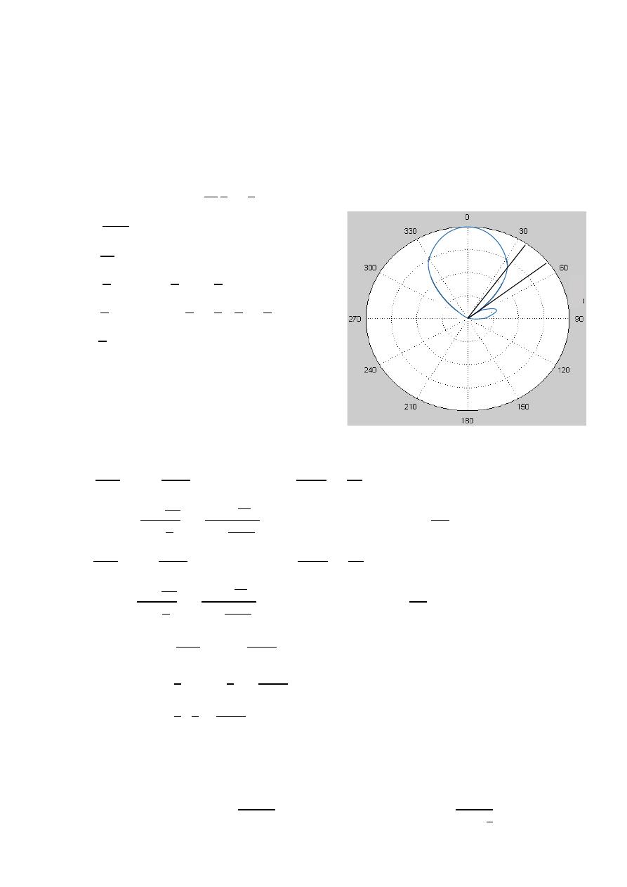
84
ﺎﺋﯿﺔــﺑﺮﮭﻜﻟا ﺔﺳﺪﻨﮭﻟا ﻢﺴﻗ ﻞــــﺻﻮﻤﻟا ﺔﻌﻣﺎﺟ
ﺎﻻتــﺼﺗﻻاو ﻚـــﯿﻧوﺮﺘﻜﻟﻻا عﺮـــــــــــــــﻓ
ﺎروديــﺒﻟا ﺪﻤﺤﻣ ﺪﯾﺆﻣ ناوﺮﻣ ﺐﻟﺎﻄﻟا داﺪﻋا
Ex:-
An array of 10 isotropic elements, are placed along the z-axis a distance
/4
Assuming uniform distribution & progressive phase
= − /2 , find:
1- Width of the principle maximum.
2- Amplitude of the first side lobe level.
3- Amplitude of the second side lobe level.
4- HPBW.
The solution:-
=
2
4
=
2
= −
∴ end fire
1-
=
±
first null
= 1
(
+
) =
±
− =
±
= − + , +
=
0.3
,
0.7
=
0.6 , 1.4
=
0.6
⟹
=
−1
(0.6)
=
53.13
Width of the principle maximum (FNBW)
=
2
|
0 − 53.13
o
| =
106.26
o
2-
=
±
⟹
= 1 ,
=
AF =
2
2
=
3
2
3
2×10
= 2.2
⟹
AF = 20 log
2.2
10
=
−
13.15
3-
=
±
⟹
= 2 ,
=
AF =
2
2
=
5
2
5
2×10
= 1.4
AF = 20 log
1.4
10
=
−
17
4-
=
2
− ±
2.782
=
2
−
−
2
±
2.782
10
=
2
2
±
2.782
10
⟹
= 34.6
HPBW
= 2|
−
|
HPBW
= 2|0 − 34.6 |
HPBW
= 69.2
or HPBW
= 2
1 −
1.391
⟹
HPBW
= 2
1 −
1.391
(
10
)
4
= 69.2
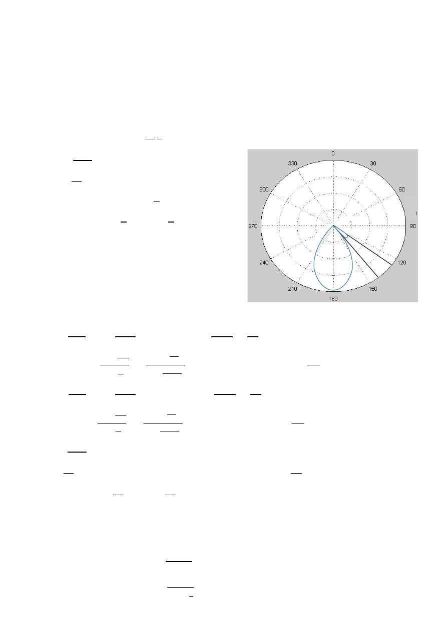
85
ﺎﺋﯿﺔــﺑﺮﮭﻜﻟا ﺔﺳﺪﻨﮭﻟا ﻢﺴﻗ ﻞــــﺻﻮﻤﻟا ﺔﻌﻣﺎﺟ
ﺎﻻتــﺼﺗﻻاو ﻚـــﯿﻧوﺮﺘﻜﻟﻻا عﺮـــــــــــــــﻓ
ﺎروديــﺒﻟا ﺪﻤﺤﻣ ﺪﯾﺆﻣ ناوﺮﻣ ﺐﻟﺎﻄﻟا داﺪﻋا
Ex:-
An array of 10 isotropic elements, are placed along the z-axis a distance
/2
A part assuming uniform amplitude & progressive phase is
180 , determine:
1- First null beam width.
2- first and second side lobe levels .
3- first side lobe beam width .
4- HPBW.
The solution:-
=
2
2
=
,
=
⟹
=
∴ end fire
1-
=
±
first null
= 1
(
+
) =
±
+
=
±
= − , − −
=
−0.8
,
−1.2
=
−0.8 , −1.2
=
−0.8
⟹
=
−1
(−0.8)
=
143.13
FNBW
=
2
|
180
o
− 143.13
o
| =
73.74
o
2-
=
±
⟹
= 1 ,
=
AF =
2
2
=
3
2
3
2×10
= 2.2
⟹
AF = 20 log
2.2
10
=
−
13.15
=
±
⟹
= 2 ,
=
AF =
2
2
=
5
2
5
2×10
= 1.4
AF = 20 log
1.4
10
=
−
17
3-
=
±
first null
2 = 1
(
+
) =
±2
⟹
+
=
±
=
− , −
−
⟹
2
=
−0.6
,
−1.4
=
−0.6 , −1.4
⟹
=
−0.6
=
−1
(−0.6)
⟹
=
126.87
FSLBW
=
143.13
o
− 126.87
o
=
16.26
o
4- HPBW
= 2
1 −
1.391
HPBW
= 2
1 −
1.391
(
10
)
2
= 48.6
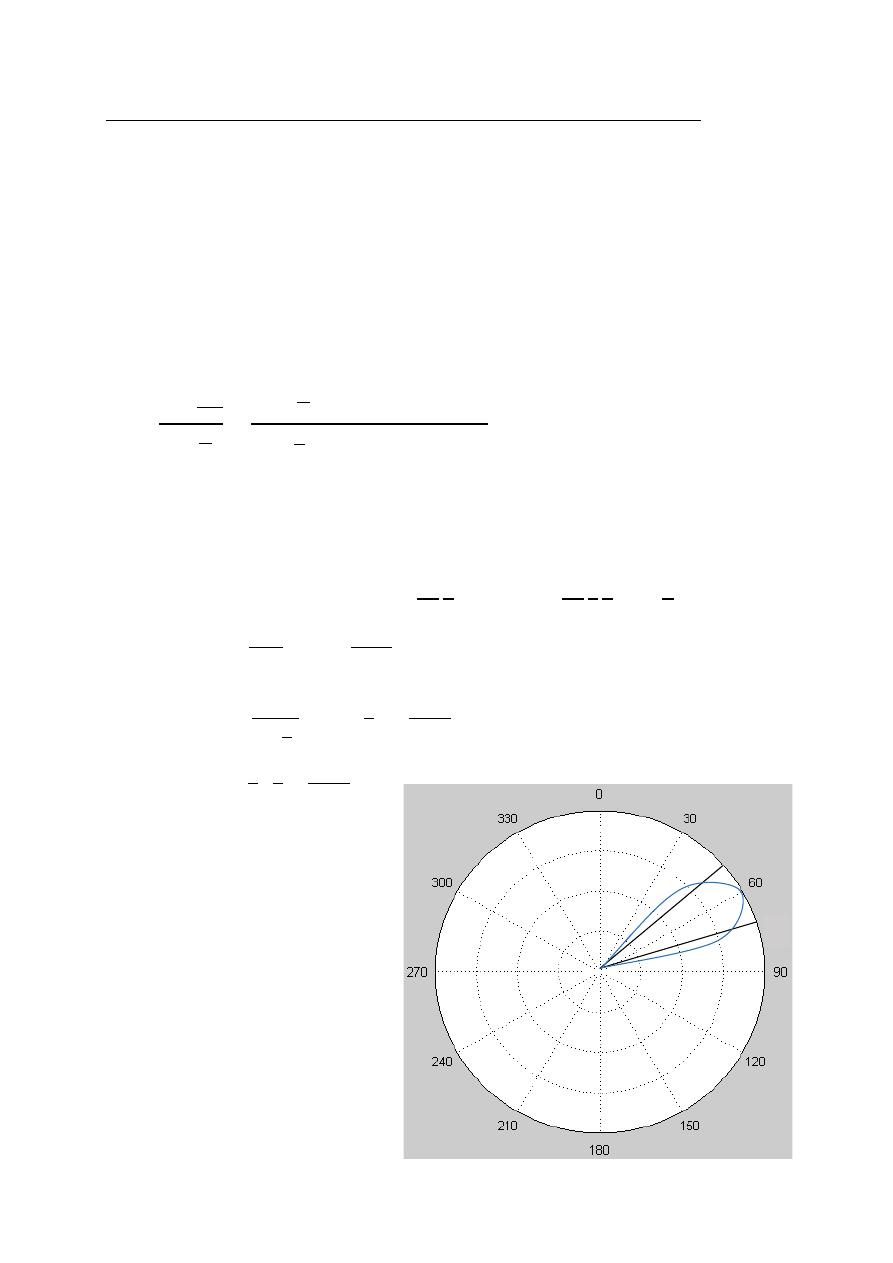
86
ﺎﺋﯿﺔــﺑﺮﮭﻜﻟا ﺔﺳﺪﻨﮭﻟا ﻢﺴﻗ ﻞــــﺻﻮﻤﻟا ﺔﻌﻣﺎﺟ
ﺎﻻتــﺼﺗﻻاو ﻚـــﯿﻧوﺮﺘﻜﻟﻻا عﺮـــــــــــــــﻓ
ﺎروديــﺒﻟا ﺪﻤﺤﻣ ﺪﯾﺆﻣ ناوﺮﻣ ﺐﻟﺎﻄﻟا داﺪﻋا
Phased array (Scanning array) Uniform Amplitude & Spacing
Assume that the maximum radiation of the array is required to be oriented at
an angle
(0 ≤
≤ 180 ).
To accomplish this , the phase excitation (
∝), between the elements most be
Adjusted so that :
=
+
Maximum radiation occur when
= 0
0 =
+
⟹
= −
=
−
AF =
2
2
=
2
−
o
1
2
−
o
Ex:-
Find the HPBW of a 10 element uniform uniform scanning array of isotropic
Sources placed along the z-axis the spacing between the elements is
/4 and
the maximum is directed at
60 from its axis.
The solution:-
= −
=
−
2
4
60 =
−
2
4 2
=
−
4
=
2
− ±
2.782
=
2
4
−
−
4
±
2.782
10
=
2
4
±
2.782
10
= 47 ,
= 71
HPBW
=
−
HPBW
= 71.16 − 47.37
HPBW
= 24
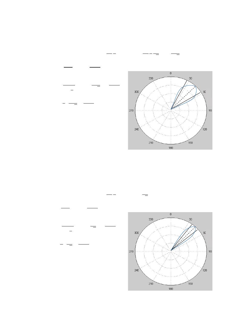
87
ﺎﺋﯿﺔــﺑﺮﮭﻜﻟا ﺔﺳﺪﻨﮭﻟا ﻢﺴﻗ ﻞــــﺻﻮﻤﻟا ﺔﻌﻣﺎﺟ
ﺎﻻتــﺼﺗﻻاو ﻚـــﯿﻧوﺮﺘﻜﻟﻻا عﺮـــــــــــــــﻓ
ﺎروديــﺒﻟا ﺪﻤﺤﻣ ﺪﯾﺆﻣ ناوﺮﻣ ﺐﻟﺎﻄﻟا داﺪﻋا
Ex:-
Find the HPBW of a 10 element uniform uniform scanning array of isotropic
Sources placed along the z-axis the spacing between the elements is
/4 and
the maximum is directed at
45 from its axis.
The solution:-
= −
=
−
2
4
45 =
−
2
4
1
2
=
−
2 2
=
2
− ±
2.782
=
2
4
−
−
2 2
±
2.782
10
=
2
2 2
±
2.782
10
= 27.84 ,
= 58
HPBW
=
−
HPBW
= 58 − 27.84
HPBW
= 30
Ex:-
Find the HPBW of a 10 element uniform uniform scanning array of isotropic
Sources placed along the z-axis the spacing between the elements is
/2 and
the maximum is directed at
45 from its axis.
The solution:-
= −
=
−
2
2
45 = −
2
=
2
− ±
2.782
=
2
2
−
−
2
±
2.782
10
=
1
2
±
2.782
10
= 37.3 ,
= 51.8
HPBW
=
−
HPBW
= 51.8 − 37.3
HPBW
= 14.5
45°
45°
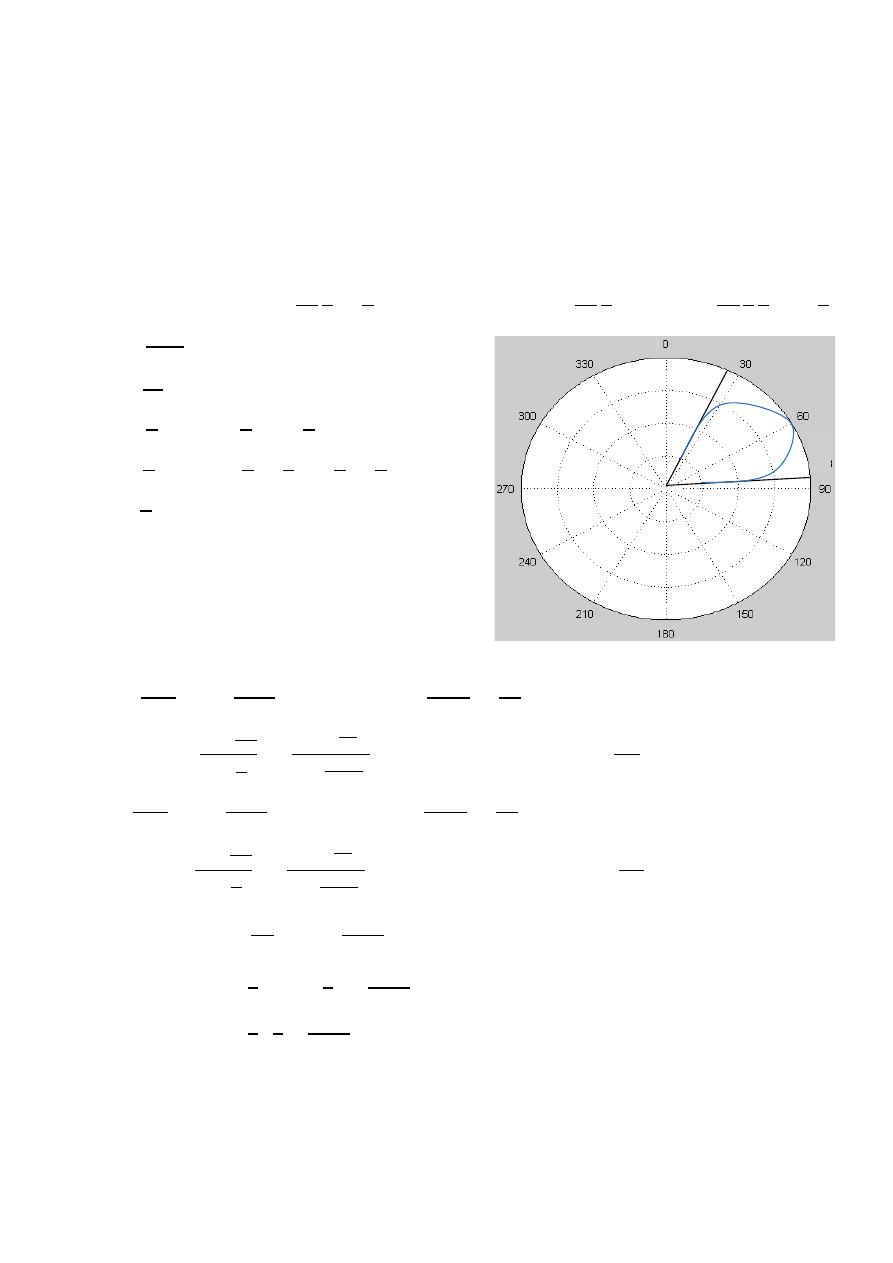
88
ﺎﺋﯿﺔــﺑﺮﮭﻜﻟا ﺔﺳﺪﻨﮭﻟا ﻢﺴﻗ ﻞــــﺻﻮﻤﻟا ﺔﻌﻣﺎﺟ
ﺎﻻتــﺼﺗﻻاو ﻚـــﯿﻧوﺮﺘﻜﻟﻻا عﺮـــــــــــــــﻓ
ﺎروديــﺒﻟا ﺪﻤﺤﻣ ﺪﯾﺆﻣ ناوﺮﻣ ﺐﻟﺎﻄﻟا داﺪﻋا
Ex:-
A 10 element uniform scanning array of isotropic sources placed along
the z-axis the spacing between the elements is
/4 and the maximum is
directed at
60 determine :
1- Width of the principle maximum.
2- The amplitude of the first side lobe.
3- The amplitude of the second side lobe.
4- HPBW.
The solution:-
=
2
4
=
2
,
=
−
= −
2
4
60 =
−
2
4
1
2
=
−
4
1-
=
±
first null
= 1
(
+
) =
±
−
=
±
= + , − +
=
0.45
,
0.05
=
0.9 , 0.1
=
−1
(0.9)
⟹
=
25.84
=
−1
(0.1)
⟹
=
84.26
FNBW
=
84.26
o
− 25.84
o
=
58.42
o
2-
=
±
⟹
= 1 ,
=
AF =
2
2
=
3
2
3
2×10
= 2.2
⟹
AF = 20 log
2.2
10
=
−
13.15
3-
=
±
⟹
= 2 ,
=
AF =
2
2
=
5
2
5
2×10
= 1.4
⟹
AF = 20 log
1.4
10
=
−
17
4-
=
1
− ±
2.782
=
2
−
−
4
±
2.782
10
=
2
4
±
2.782
10
⟹
= 71 ,
= 47.4
HPBW
=
−
HPBW
= 71 − 47.4
HPBW
= 23.6
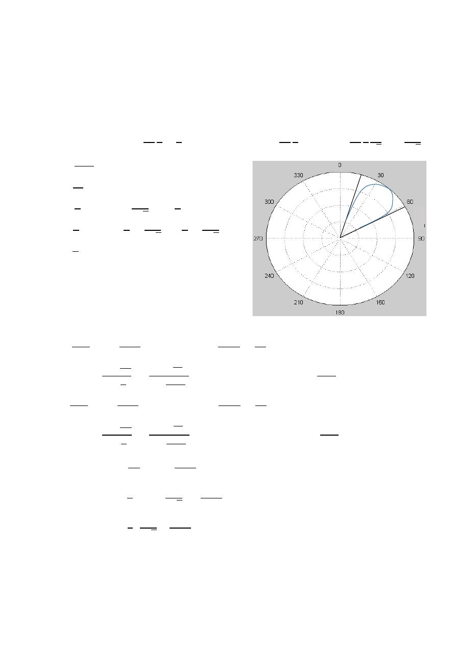
89
ﺎﺋﯿﺔــﺑﺮﮭﻜﻟا ﺔﺳﺪﻨﮭﻟا ﻢﺴﻗ ﻞــــﺻﻮﻤﻟا ﺔﻌﻣﺎﺟ
ﺎﻻتــﺼﺗﻻاو ﻚـــﯿﻧوﺮﺘﻜﻟﻻا عﺮـــــــــــــــﻓ
ﺎروديــﺒﻟا ﺪﻤﺤﻣ ﺪﯾﺆﻣ ناوﺮﻣ ﺐﻟﺎﻄﻟا داﺪﻋا
Ex:-
A uniform linear array of 16 isotropic point sources are placed along
the z-axis with a spacing of
/4 . if the maximum is directed at 45 from
its axis , determine :
1- Width of the principle maximum.
2- first and second side lobe levels.
3- HPBW.
The solution:-
=
2
4
=
2
,
=
−
=
−
2
4
45 =
−
2
4
1
2
=
−
2 2
1-
=
±
first null
= 1
(
+
) =
±
−
−
2
√
2
=
±
= +
2
√
2
,
− +
2
√
2
=
0.48
,
0.23
=
0.96 , 0.46
=
−1
(0.96)
⟹
=
16.26
=
−1
(0.46)
⟹
=
62.6
FNBW
=
62.6
o
− 16.26
o
=
46.34
o
2-
=
±
⟹
= 1 ,
=
AF =
2
2
=
3
2
3
2×16
= 3.44
⟹
AF = 20 log
3.44
16
=
−
13.35
=
±
⟹
= 2 ,
=
AF =
2
2
=
5
2
5
2×16
= 2.12
⟹
AF = 20 log
2.12
16
=
−
17.55
3-
=
1
− ±
2.782
=
2
−
−
2 2
±
2.782
16
=
2
2 2
±
2.782
16
⟹
= 53.4 ,
= 35.1
HPBW
=
−
HPBW
= 53.4 − 35.1
HPBW
= 18.3
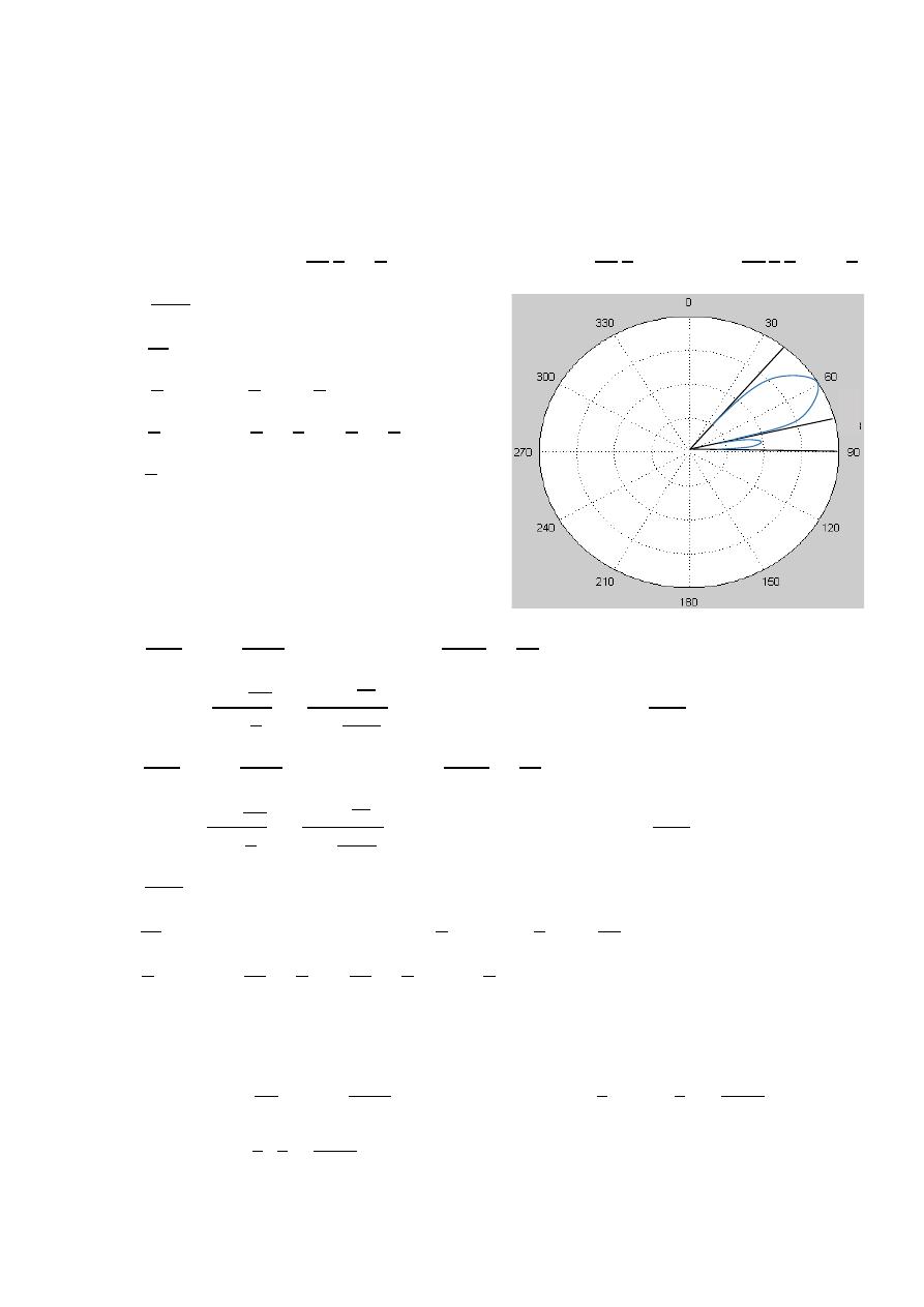
90
ﺎﺋﯿﺔــﺑﺮﮭﻜﻟا ﺔﺳﺪﻨﮭﻟا ﻢﺴﻗ ﻞــــﺻﻮﻤﻟا ﺔﻌﻣﺎﺟ
ﺎﻻتــﺼﺗﻻاو ﻚـــﯿﻧوﺮﺘﻜﻟﻻا عﺮـــــــــــــــﻓ
ﺎروديــﺒﻟا ﺪﻤﺤﻣ ﺪﯾﺆﻣ ناوﺮﻣ ﺐﻟﺎﻄﻟا داﺪﻋا
Ex:-
A uniform linear array of 16 isotropic point sources are placed along
the z-axis with a spacing of
/4 . if the maximum is directed at 60 from
its axis , determine :
1- Width of the principle maximum. 2- first and second side lobe levels.
3- first side lobe beam width. 4- HPBW.
The solution:-
=
2
4
=
2
,
=
−
= −
2
4
60 =
−
2
4
1
2
=
−
4
1-
=
±
first null
= 1
(
+
) =
±
−
=
±
= + , − +
=
0.375
,
0.125
=
0.75 , 0.25
=
−1
(0.75)
⟹
=
41.4
=
−1
(0.25)
⟹
=
75.5
FNBW
=
75.5
o
− 41.4
o
=
34.1
o
2-
=
±
⟹
= 1 ,
=
AF =
2
2
=
3
2
3
2×16
= 3.44
⟹
AF = 20 log
3.44
16
=
−
13.35
=
±
⟹
= 2 ,
=
AF =
2
2
=
5
2
5
2×16
= 2.12
⟹
AF = 20 log
2.12
16
=
−
17.55
3-
=
±
first null
= 2
(
+
) =
±2
⟹
−
=
±
=
+ , −
+
⟹
=
0.5
,
0
=
1 , 0
⟹
=
0 ,
=
90
FSLBW
=
90
o
− 75.5
o
=
14.5
4-
=
1
− ±
2.782
⟹
=
2
−
−
4
±
2.782
16
=
2
4
±
2.782
16
⟹
= 67 ,
= 52.4
HPBW
=
−
HPBW
= 67 − 52.4
⟹
HPBW = 14.6
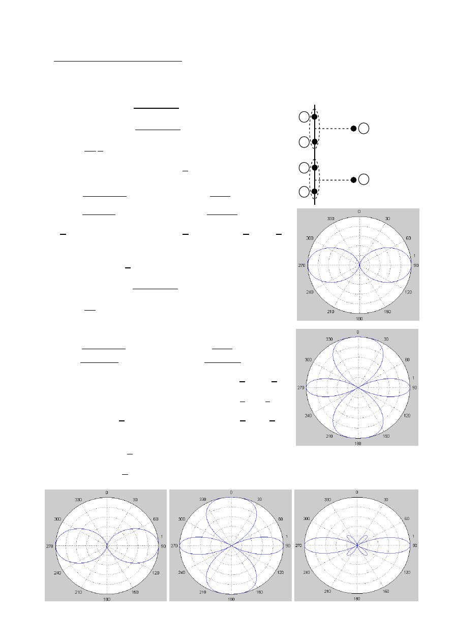
91
ﺎﺋﯿﺔــﺑﺮﮭﻜﻟا ﺔﺳﺪﻨﮭﻟا ﻢﺴﻗ ﻞــــﺻﻮﻤﻟا ﺔﻌﻣﺎﺟ
ﺎﻻتــﺼﺗﻻاو ﻚـــﯿﻧوﺮﺘﻜﻟﻻا عﺮـــــــــــــــﻓ
ﺎروديــﺒﻟا ﺪﻤﺤﻣ ﺪﯾﺆﻣ ناوﺮﻣ ﺐﻟﺎﻄﻟا داﺪﻋا
Multiplication Of Patterns
Consider a four uniform element array of isotropic sources placed along the z-axis
The spacing between the elements is
/2 and the currents are in phase ( = 0).
AF
= 2
+
2
AF
= 2
+
2
=
2
2
=
(AF ) = (AF ) =
2
nulls
max value
2
=
1
2
=
0
=
0 , ±
=
± , ± 3
=
0 , ± 2
=
±1 , ± 3
=
±
2
=
0 , ±
(AF ) =
+
2
=
2
= 2
AF
=
(
)
nulls
max value
2
2
=
1
2
2
=
0
=
0 , ±
=
±
2
, ± 3
2
=
0 , ± 1
=
±
1
2
, ±
3
2
=
±
2
, 0,
=
±
3
, ±2
3
(AF ) = [(AF ) or (AF ) ]
×
(AF )
(AF ) =
2
(
)
0.707 = cos
2
cos(
) ⟹
= 76.5 , HPBW=2(90 − 76.5 ) = 27
/2
/2
/2
4
3
2
1
=
a
b
AF
12
or AF
34
AF
t
AF
ab
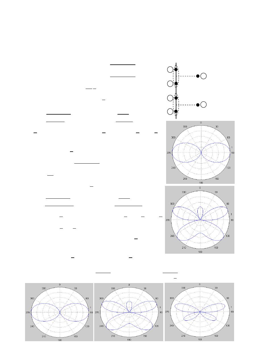
92
ﺎﺋﯿﺔــﺑﺮﮭﻜﻟا ﺔﺳﺪﻨﮭﻟا ﻢﺴﻗ ﻞــــﺻﻮﻤﻟا ﺔﻌﻣﺎﺟ
ﺎﻻتــﺼﺗﻻاو ﻚـــﯿﻧوﺮﺘﻜﻟﻻا عﺮـــــــــــــــﻓ
ﺎروديــﺒﻟا ﺪﻤﺤﻣ ﺪﯾﺆﻣ ناوﺮﻣ ﺐﻟﺎﻄﻟا داﺪﻋا
Ex:-
four isotropic sources with spacing
/2 between them are placed along
the z-axis assuming that the amplitudes of the elements 1&2 are +1 and
the amplitudes of the elements 3&4 are
−1 Use the multiplication of
patterns to find and plot the total field pattern & Find all the nulls & HPBW.
The solution:-
AF
= 2
+
2
AF
= 2
+
2
=
2
2
=
(AF ) = (AF ) =
2
nulls
max value
2
=
1
2
=
0
=
0 , ±
=
± , ± 3
=
0 , ± 2
=
±1 , ± 3
=
±
2
=
0 , ±
(AF ) =
+
2
=
2
= 2
AF
=
+
2
nulls
max value
2
+
2
=
1
2
+
2
=
0
+
2
=
0 , ±
+
2
=
±
2
, ± 3
2
=
1
2
, −
1
2
=
0, ±1
=
60 , 120
=
±
2
, 0,
(AF ) = [(AF ) or (AF ) ]
×
(AF )
(AF ) =
2
+
2
HPBW
= 2 90 −
1.391
= 2 90 −
1.391
(
4
)
2
= 25.58
/2
/2
/2
4
3
2
1
=
a
b
AF
12
or AF
34
AF
t
AF
ab
−1∠180
−1∠180
1∠0
1∠0
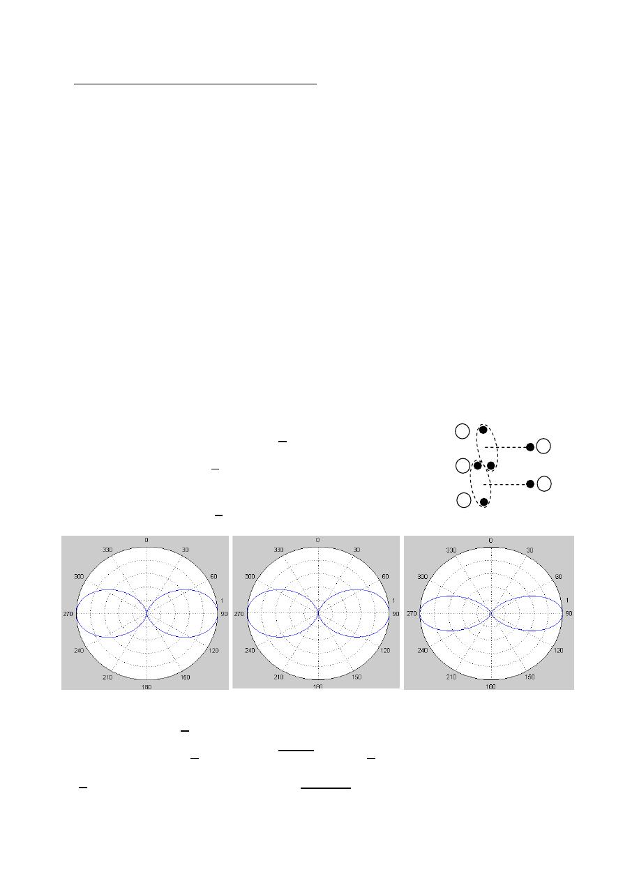
93
ﺎﺋﯿﺔــﺑﺮﮭﻜﻟا ﺔﺳﺪﻨﮭﻟا ﻢﺴﻗ ﻞــــﺻﻮﻤﻟا ﺔﻌﻣﺎﺟ
ﺎﻻتــﺼﺗﻻاو ﻚـــﯿﻧوﺮﺘﻜﻟﻻا عﺮـــــــــــــــﻓ
ﺎروديــﺒﻟا ﺪﻤﺤﻣ ﺪﯾﺆﻣ ناوﺮﻣ ﺐﻟﺎﻄﻟا داﺪﻋا
Binomial Array (non uniform array)
For some application a single narrow lobe without minor lobes in desired
It is possible to obtain a pattern with high directivity and no minor lobes.
if the amplitude of the sources in the array correspond to the coefficients of
Binomial series these coefficients are displayed by Pascal's triangle.
Ex:-
Assume
= /2 , = 0 , N = 3 ,find plot & HPBW for 3element Binomial array.
(
AF ) = (AF ) =
2
(
AF ) =
2
(
AF ) = [(AF ) or (AF ) ]
×
(AF )
(AF ) =
2
(
AF ) =
2
0.707(1) =
2
⟹
√0.707 =
2
ℎ
= 32.77
⟹
=
2×32.77
180
⟹
= 68.6
HPBW
= 2|90 − 68.6 |
HPBW
= 42.8
AF
12
or AF
23
AF
ab
AF
t
= /2
N=1
a
b
2
3
1
/2
/2
N=6
N=8
N=9
N=10
N=7
N=4
N=3
N=2
N=5
1
1
1
1
1
1
1
1
1
1
1
1
1
1
1
1
1
1
1
2
3
4
6
7
8
36
9
36
84
126
126
9
84
8
28
28
56
56
70
7
21
21
35
35
3
4
10
5
10
5
6
6
15
15
20
Pascal's triangle
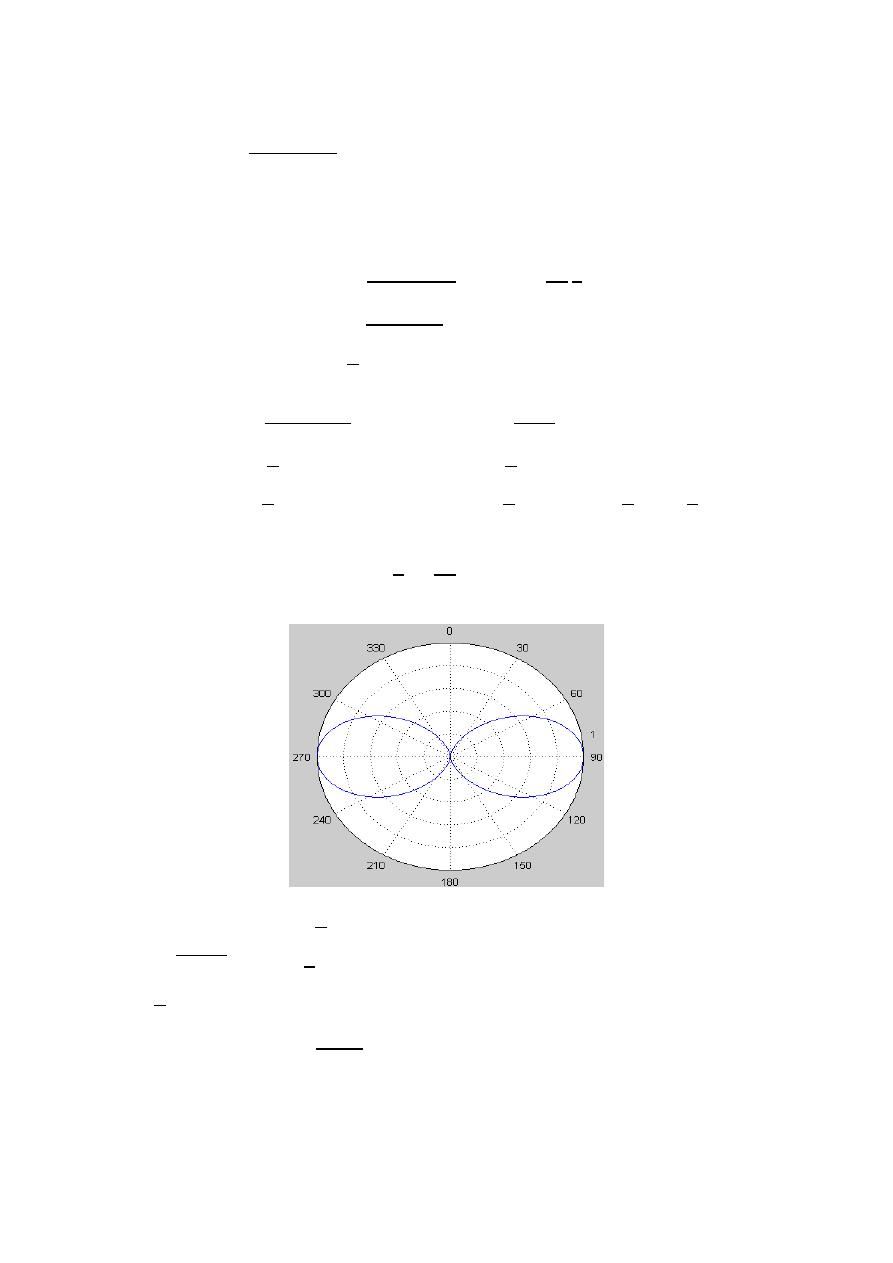
94
ﺎﺋﯿﺔــﺑﺮﮭﻜﻟا ﺔﺳﺪﻨﮭﻟا ﻢﺴﻗ ﻞــــﺻﻮﻤﻟا ﺔﻌﻣﺎﺟ
ﺎﻻتــﺼﺗﻻاو ﻚـــﯿﻧوﺮﺘﻜﻟﻻا عﺮـــــــــــــــﻓ
ﺎروديــﺒﻟا ﺪﻤﺤﻣ ﺪﯾﺆﻣ ناوﺮﻣ ﺐﻟﺎﻄﻟا داﺪﻋا
In general the expression for Binomial array is given by :
AF =
+
2
Ex:-
Determine & plot the array factor of 4- element Binomial array assume
= /2 , = 0 .
The solution:-
AF =
+
2
,
=
2
2
=
,
= 0
AF =
+0
2
AF =
2
nulls
max value
2
=
1
2
=
0
=
0 , ±
=
± , ± 3
=
0 , ± 2
=
±1 , ± 3
=
±
2
±
3
2
=
0
,
±
0.707(1) =
2
√0.707 =
2
ℎ
= 27
=
2×27
180
⟹
= 725
HPBW
= 2|
−
|
HPBW
= 2|90 − 72.5 |
HPBW
= 35
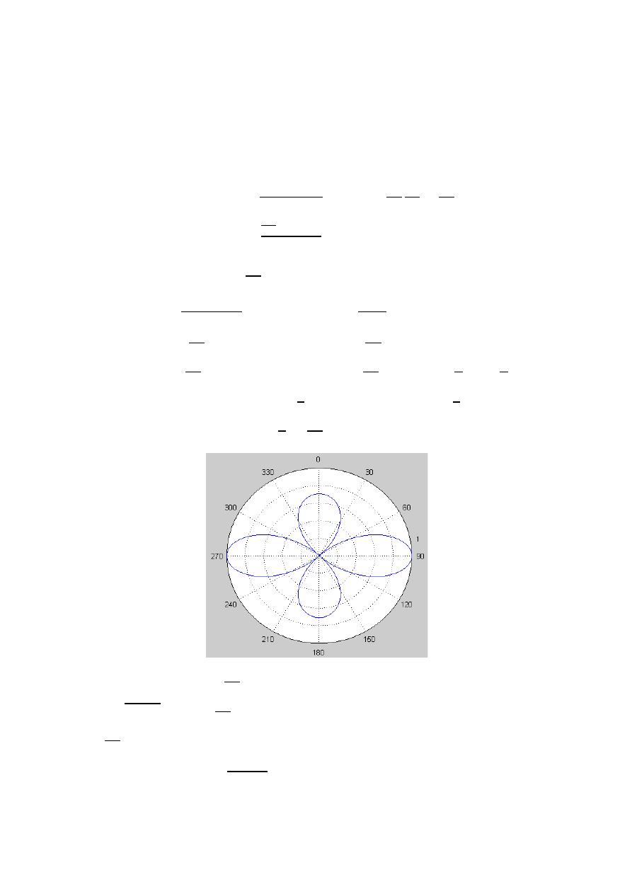
95
ﺎﺋﯿﺔــﺑﺮﮭﻜﻟا ﺔﺳﺪﻨﮭﻟا ﻢﺴﻗ ﻞــــﺻﻮﻤﻟا ﺔﻌﻣﺎﺟ
ﺎﻻتــﺼﺗﻻاو ﻚـــﯿﻧوﺮﺘﻜﻟﻻا عﺮـــــــــــــــﻓ
ﺎروديــﺒﻟا ﺪﻤﺤﻣ ﺪﯾﺆﻣ ناوﺮﻣ ﺐﻟﺎﻄﻟا داﺪﻋا
Ex:-
A four element binomial array of in phase isotropic sources, placed along
The z-axis a distance
3 /4 part.
1- Find the nulls and maxima of the array.
2- Plot the array factor.
3- Determine the HPBW of the array.
The solution:-
AF =
+
2
,
=
2 3
4
=
3
2
,
= 0
AF =
3
2
+0
2
AF =
3
4
nulls
max value
-
1
3
4
=
1
3
4
=
0
=
0 , ±
=
± , ± 3
=
0 , ±
4
3
=
±
2
3
, ± 2
=
±
2
±
3
2
=
48
,
132
2-
3-
0.707(1) =
3
4
√0.707 =
3
4
ℎ
= 27
=
4×27
3×180
⟹
= 78.5
HPBW
= 2|
−
|
HPBW
= 2|90 − 78.5 |
HPBW
= 23
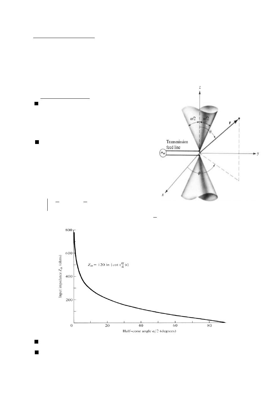
96
ﺎﺋﯿﺔــﺑﺮﮭﻜﻟا ﺔﺳﺪﻨﮭﻟا ﻢﺴﻗ ﻞــــﺻﻮﻤﻟا ﺔﻌﻣﺎﺟ
ﺎﻻتــﺼﺗﻻاو ﻚـــﯿﻧوﺮﺘﻜﻟﻻا عﺮـــــــــــــــﻓ
ﺎروديــﺒﻟا ﺪﻤﺤﻣ ﺪﯾﺆﻣ ناوﺮﻣ ﺐﻟﺎﻄﻟا داﺪﻋا
Broad Band Dipoles
The radiation characteristic (such as pattern , impedance , gain , ete) are very
sensitivity to frequency . the degree to which they change as a function of
frequency depends on antenna bandwidth.
for applications that require coverage of a broad range of frequencies such as
television reception of all channels wide band antenna as are needed.
Biconical Antenna
-
1
One simplest configuration that can be
used to achieve broad band characteristic
is the biconical antenna formed by placing
two cones of finite extent together.
The application of a voltage vi at the input
terminals will produce out going sperical
waves, which in turn produce a current I
along the surface of the cone.
And voltage V between the cones.
Input impedance.
=
4
For free space medium
= 120
4
The antenna becomes more broad band as the cone angle increase.
Wherever one of the cones is mounted on an infinite plane conductor
(the lower cone is replaced by a ground plane), it forms a unipole and its
input impedance is one half of the two cone structure.
antenna
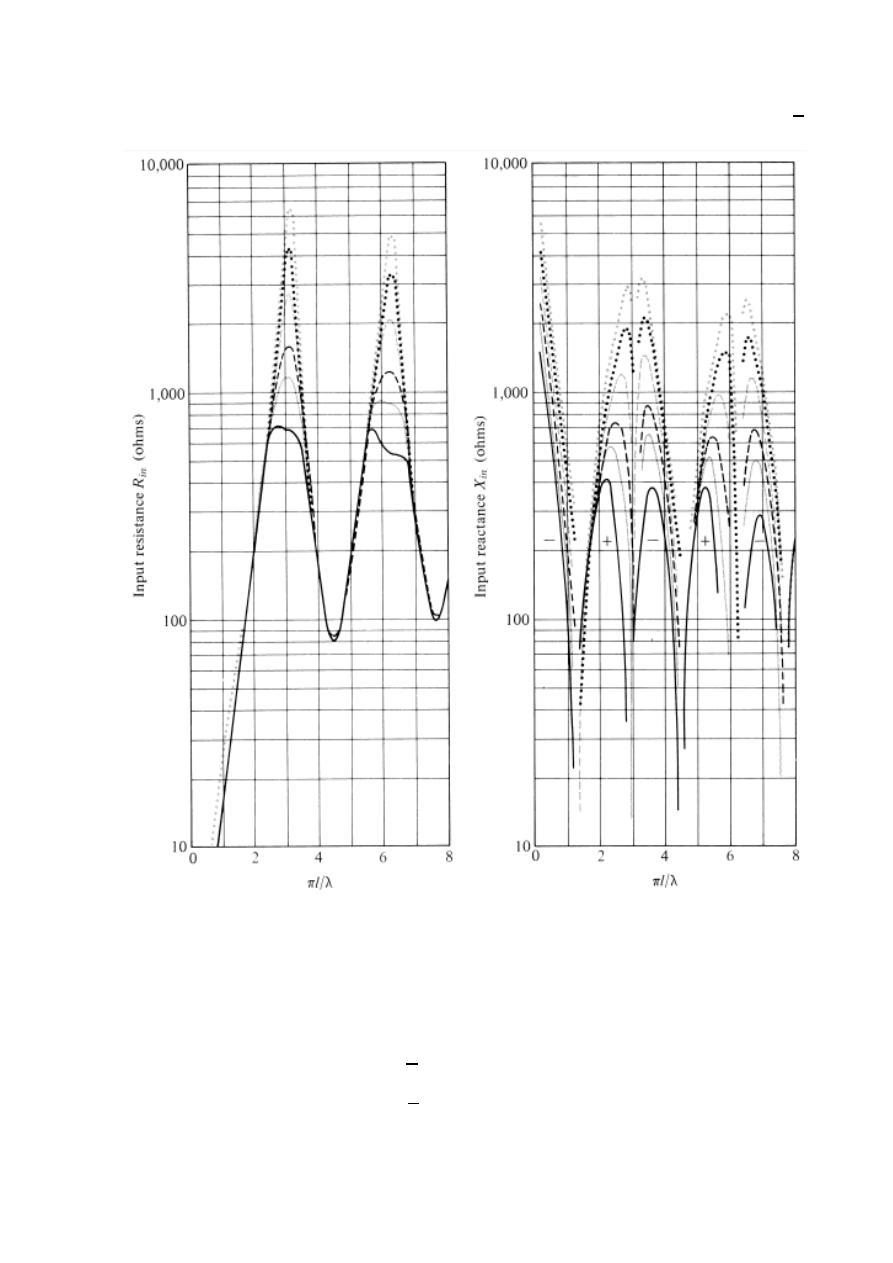
97
ﺎﺋﯿﺔــﺑﺮﮭﻜﻟا ﺔﺳﺪﻨﮭﻟا ﻢﺴﻗ ﻞــــﺻﻮﻤﻟا ﺔﻌﻣﺎﺟ
ﺎﻻتــﺼﺗﻻاو ﻚـــﯿﻧوﺮﺘﻜﻟﻻا عﺮـــــــــــــــﻓ
ﺎروديــﺒﻟا ﺪﻤﺤﻣ ﺪﯾﺆﻣ ناوﺮﻣ ﺐﻟﺎﻄﻟا داﺪﻋا
The relationship between input impedance and frequency for different values of
4
Ex:-
A
300Ω twin load T.L is attached by a biconical antenna. Determine
The cone angle , that will match the line to an infinite length biconical
antenna.
The solution:-
=
is match
= 120
4
300 = 120
4
= 18.7
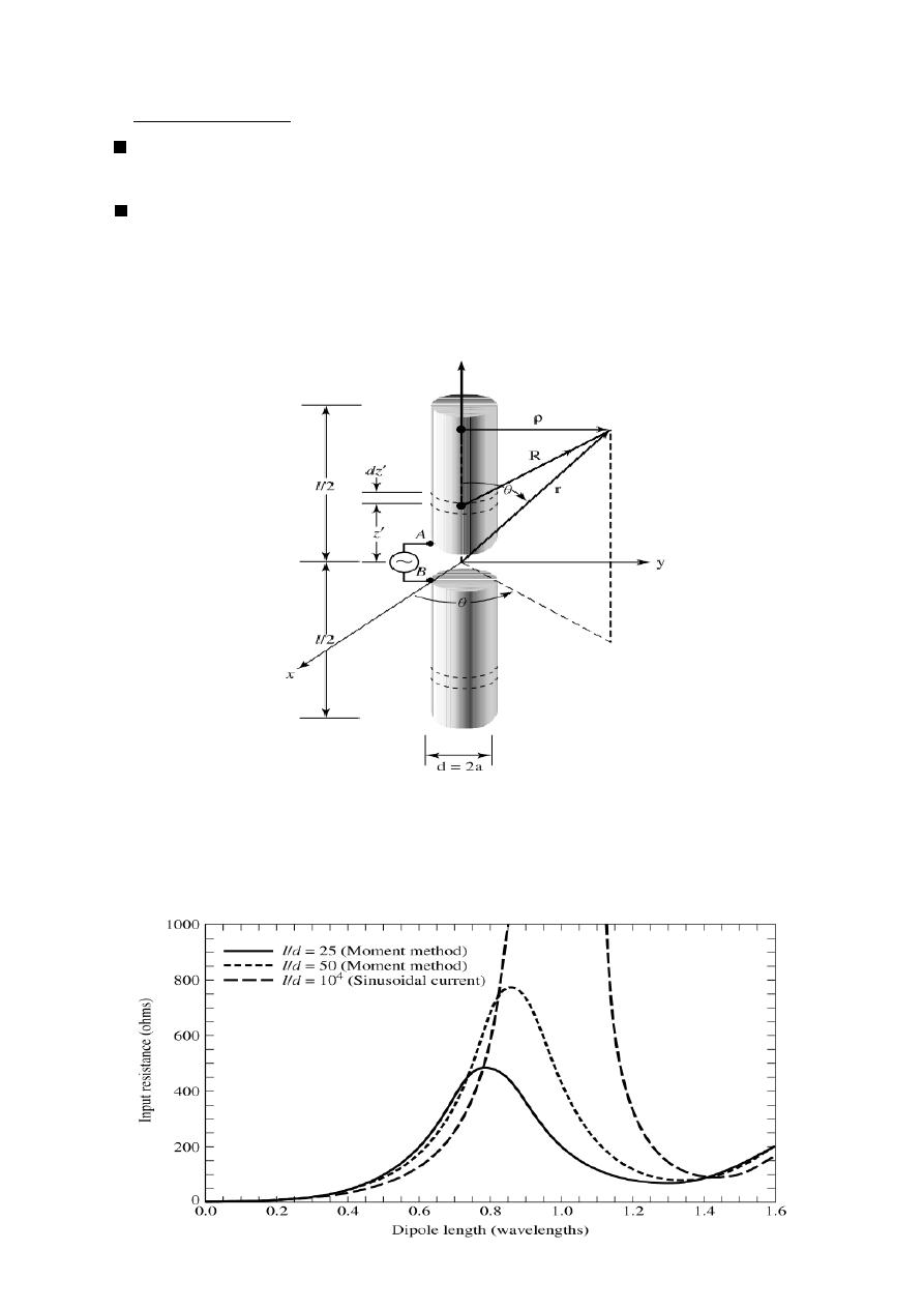
98
ﺎﺋﯿﺔــﺑﺮﮭﻜﻟا ﺔﺳﺪﻨﮭﻟا ﻢﺴﻗ ﻞــــﺻﻮﻤﻟا ﺔﻌﻣﺎﺟ
ﺎﻻتــﺼﺗﻻاو ﻚـــﯿﻧوﺮﺘﻜﻟﻻا عﺮـــــــــــــــﻓ
ﺎروديــﺒﻟا ﺪﻤﺤﻣ ﺪﯾﺆﻣ ناوﺮﻣ ﺐﻟﺎﻄﻟا داﺪﻋا
Cylindrical dipole
-
2
A simple and inexpensive antenna which has broad band frequency characteristic
is a cylindrical dipole (wire of infinite diameter and length).
A very thin linear dipole has very narrow band Radiation characteristics .
Any small change is the operating frequency will result in large change in its
Operational behavior.
one method by which its acceptable operational Band width can be enlarged
with be to decrease the L/d ratio.
For example, an antenna with a L/d=5000 has an acceptable bandwidth
of about 3%, which is a small fraction of the center frequency
an antenna of the same length but with a L/d=250
has a bandwidth of about 30% .
Cylindrical dipole
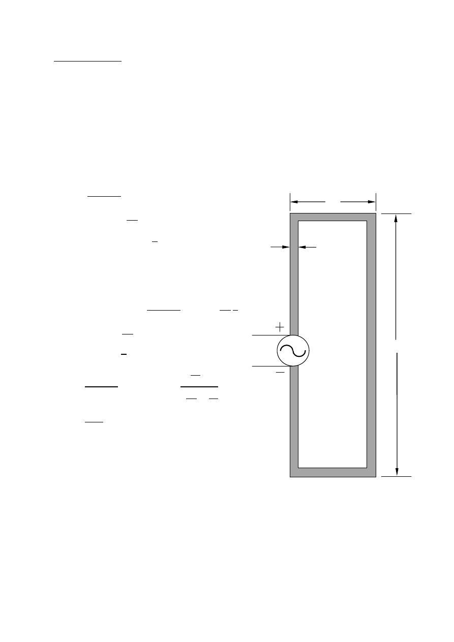
99
ﺎﺋﯿﺔــﺑﺮﮭﻜﻟا ﺔﺳﺪﻨﮭﻟا ﻢﺴﻗ ﻞــــﺻﻮﻤﻟا ﺔﻌﻣﺎﺟ
ﺎﻻتــﺼﺗﻻاو ﻚـــﯿﻧوﺮﺘﻜﻟﻻا عﺮـــــــــــــــﻓ
ﺎروديــﺒﻟا ﺪﻤﺤﻣ ﺪﯾﺆﻣ ناوﺮﻣ ﺐﻟﺎﻄﻟا داﺪﻋا
Folded dipole
To achieve good directional pattern characteristics and at the same time provide
good matching to practical lines.
/4 ≪ ℓ <
The most widely used dipole is that whose overall length is L
= /2 .
(
= 73 + 4.25 &
= 1.64)
when the spacing between the two large side is very
small (S
< ) (S < 0.05 ) it is called folded dipole.
=
4
2
+
=
ℓ
2
= 0.733
S
: dipole impedance.
Ex:-
Determine
if
ℓ
= /2 ,
= 75Ω
The solution:-
=
4
2
+
,
ℓ =
2
2
=
=
ℓ
2
=
2
= ∞
=
4
2
+
=
→∞
4
2
+
=
4
0+1
= 4
= 4 × 75 = 300Ω
S
2a
=
d
l
V
Folded dipole

100
ﺎﺋﯿﺔــﺑﺮﮭﻜﻟا ﺔﺳﺪﻨﮭﻟا ﻢﺴﻗ ﻞــــﺻﻮﻤﻟا ﺔﻌﻣﺎﺟ
ﺎﻻتــﺼﺗﻻاو ﻚـــﯿﻧوﺮﺘﻜﻟﻻا عﺮـــــــــــــــﻓ
ﺎروديــﺒﻟا ﺪﻤﺤﻣ ﺪﯾﺆﻣ ناوﺮﻣ ﺐﻟﺎﻄﻟا داﺪﻋا
Ex:-
A two element folded dipole of identical wires has an
ℓ/ = 500 and
center to center spacing of
6.13 × 10
between the wires. If the radius
of the wire is
0.479 × 10
, compute the input impedance of the folded
dipole (assume
= 65 + 10 Ω
)
The solution:-
=
4
2
+
= 0.733
S
= 0.733(120 )
6.13×10
−3
0.479×10
−3
= 306 Ω
ℓ
= 500
⟹
ℓ
= 500
⟹
ℓ
= 500(2 )
ℓ
= 500(2 × 0.479 × 10
−3
)
ℓ
= 0.479
=
ℓ
2
= 306
2 0.479
2
= 4631.5 Ω
=
4× 4631.5×(65+ 10)
2(65+ 10)+ 4631.5
=
4× 4631.5×(65+ 10)
130+ 20+ 4631.5
=
4× 4631.5×(65+ 10)
130+ 4651.5
=
4×4631.5∠90
o
×65.8∠8.75
o
4653.3∠88.7
o
=
1219010.8∠98.75
o
4653.3∠88.7
o
=
1219010.8
4653.3
∠
98.75
o
− 88.7
o
=
262∠10.05
o
Ω
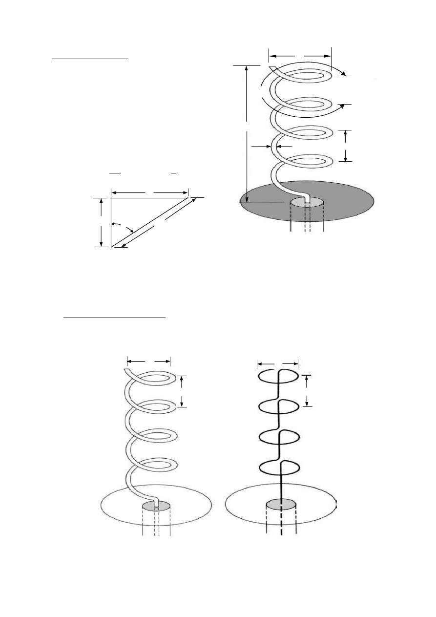
101
ﺎﺋﯿﺔــﺑﺮﮭﻜﻟا ﺔﺳﺪﻨﮭﻟا ﻢﺴﻗ ﻞــــﺻﻮﻤﻟا ﺔﻌﻣﺎﺟ
ﺎﻻتــﺼﺗﻻاو ﻚـــﯿﻧوﺮﺘﻜﻟﻻا عﺮـــــــــــــــﻓ
ﺎروديــﺒﻟا ﺪﻤﺤﻣ ﺪﯾﺆﻣ ناوﺮﻣ ﺐﻟﺎﻄﻟا داﺪﻋا
Antenna
Helical
D: Diameter.
S: spacing between each turn.
Total length of the antenna = NS
Total length of the wire = NL
o
L
o
:
length of the wire between each turn.
C = D circumference of the helix.
: pitch angle.
=
S
=
S
The radiation characteristics of the antenna can be varied by
controlling
the size of its geometrical properties compared to the wavelength mode
operation
.
1- Normal mode (
≪ )
The field radiated by the antenna is maximum in a plane normal to the helix
Axis and minimum along its axis.
The fields are obtained by superposition of the fields from the elemental
radiators (circular loop & short dipole)
Normal mode
Equivalent
S
S
D
D
D
Helical Antenna
L
2a
S
L
o
S
α
C =
π
D
L
o
102
ﺎﺋﯿﺔــﺑﺮﮭﻜﻟا ﺔﺳﺪﻨﮭﻟا ﻢﺴﻗ ﻞــــﺻﻮﻤﻟا ﺔﻌﻣﺎﺟ
ﺎﻻتــﺼﺗﻻاو ﻚـــﯿﻧوﺮﺘﻜﻟﻻا عﺮـــــــــــــــﻓ
ﺎروديــﺒﻟا ﺪﻤﺤﻣ ﺪﯾﺆﻣ ناوﺮﻣ ﺐﻟﺎﻄﻟا داﺪﻋا
1- For the short dipole.
=
ℓ
−
4
(ℓ = )
=
S
−
4
2- Small circular loop.
=
120
2
2
=
2
2
where D = 2a
=
2
⟹
=
2
=
2
2
2
−
4
⟺
=
2
−
4
&
are in the phase quadrature
Axial ratio(AR)
=
=
S
−
4
2
−
4
=
S
2
=
S
2
2
2
=
2 S
2
=
2 S
2
0 ≤
≤ ∞ depending on D & S
= 0 at
= 0 horizontal polarization (H.P)
= ∞ at
= 0 vertical polarization (V.P)
= 1
⟹
1 =
2 S
2
⟹
=
√
2 S circular polarization (C.P)
=
S
C
=
S
2 S
=
S
2
2 S
=
S
2
in terms of S
=
S
C
=
(
)
2
2
=
(
)
2
2 (
)
=
2
in terms of D
=
S
=
2
or
C = πD
S
L
o

103
ﺎﺋﯿﺔــﺑﺮﮭﻜﻟا ﺔﺳﺪﻨﮭﻟا ﻢﺴﻗ ﻞــــﺻﻮﻤﻟا ﺔﻌﻣﺎﺟ
ﺎﻻتــﺼﺗﻻاو ﻚـــﯿﻧوﺮﺘﻜﻟﻻا عﺮـــــــــــــــﻓ
ﺎروديــﺒﻟا ﺪﻤﺤﻣ ﺪﯾﺆﻣ ناوﺮﻣ ﺐﻟﺎﻄﻟا داﺪﻋا
Ex:-
Design a five turn helical antenna which operates at 400 MHz in the normal
mode. the spacing between turns is
/50. It is desired that the antenna posses
circular polarization. determine the far zone electric field intensity at 10 Km
distance in the direction of maximum radiation assume
(
= 1 ).
The solution:- N = 5 , F = 400MHz ,
S =
50
=
=
3×10
8
400×10
6
= 0.75 m
S =
0.75
50
= 0.015m
=
2
=
2
0.75
= 8.4
Circular polarization in normal mode
⟹
AR = 1
= 1
⟹
1 =
2 S
2
=
√
2 S =
√
2 × 0.75 × 0.015 = 0.15 m
=
⟹
=
=
0.15
= 0.0477m
=
2
=
0.0477
2
= 0.02385 m
=
S
C
=
0.015
0.15
= 5.7106
=
S
−
4
|
| =
8.4×120 ×1×0.015
4 ×10×1000
90
|
| = 378 V/m for one turn
|
| = 378 × 5 × 10
= 1890 V/m
=
2
−
4
=
120 × 8.4×0
.
02385
2
×1
4×10×1000
90
= 378 V/m for one turn
= 378 × 5 × 10
= 1890 V/m
|
| = |
| +
|
| = 1890 ⃗ + 1890 ⃗
V/m

104
ﺎﺋﯿﺔــﺑﺮﮭﻜﻟا ﺔﺳﺪﻨﮭﻟا ﻢﺴﻗ ﻞــــﺻﻮﻤﻟا ﺔﻌﻣﺎﺟ
ﺎﻻتــﺼﺗﻻاو ﻚـــﯿﻧوﺮﺘﻜﻟﻻا عﺮـــــــــــــــﻓ
ﺎروديــﺒﻟا ﺪﻤﺤﻣ ﺪﯾﺆﻣ ناوﺮﻣ ﺐﻟﺎﻄﻟا داﺪﻋا
Ex:-
A 5- turn helical antenna which at 400 MHz operates in the normal mode.
the spacing between turns is
/50.determine the magnitude electric field at
10 Km distance in the direction of maximum radiation for the following
cases Assume
(
= 1 ) 1- V.P case.
2- H.P case , assume D =
/10.
3- C.P case.
The solution:- N = 5 , F = 400MHz ,
S =
50
=
=
3×10
8
400×10
6
= 0.75 m
S =
0.75
50
= 0.015m , =
2
=
2
0.75
= 8.4
1-
=
S
−
4
|
| =
8.4×120 ×1×0.015
4 ×10×1000
90 = 378 V/m for one turn
|
| = 378 × 5 × 10
= 1890 V/m
2-
=
10
=
0.75
10
= 0.075
⟹
=
2
=
0.075
2
= 0.0375 m
=
2
−
4
=
120 × 8.4×0
.
0375
2
×1
4×10×1000
90 = 935 V/m for one turn
= 935 × 5 × 10
= 4675 V/m
3- Circular polarization in normal mode
⟹
AR = 1
= 1
⟹
1 =
2 S
2
⟹
=
√
2 S =
√
2 × 0.75 × 0.015 = 0.15 m
=
⟹
=
=
0.15
= 0.0477m
=
2
=
0.0477
2
= 0.02385 m
=
S
−
4
|
| =
8.4×120 ×1×0.015
4 ×10×1000
90 = 378 V/m for one turn
|
| = 378 × 5 × 10
= 1890 V/m
=
2
−
4
=
120 × 8.4×0
.
02385
2
×1
4×10×1000
90 = 378 V/m for one turn
= 378 × 5 × 10
= 1890 V/m
|
| = |
| +
|
| = 1890 ⃗ + 1890 ⃗
V/m
105
ﺎﺋﯿﺔــﺑﺮﮭﻜﻟا ﺔﺳﺪﻨﮭﻟا ﻢﺴﻗ ﻞــــﺻﻮﻤﻟا ﺔﻌﻣﺎﺟ
ﺎﻻتــﺼﺗﻻاو ﻚـــﯿﻧوﺮﺘﻜﻟﻻا عﺮـــــــــــــــﻓ
ﺎروديــﺒﻟا ﺪﻤﺤﻣ ﺪﯾﺆﻣ ناوﺮﻣ ﺐﻟﺎﻄﻟا داﺪﻋا
Ex:-
A helical antenna of 4-turn is operated in the normal mode at frequency of
880 MHz & is used as an antenna for wireless cellular phone the length of
the helical is 5.7cm and diameter of each turn is 0.5cm determine the far
electric field at ( 1Km , 90° , 60°) assuming (
= 1 ).
Hint: Design & find all dimension.
The solution:- N = 4 , F = 880MHz , L = 5.7 cm , D = 0.5 cm
=
=
3×10
8
880×10
6
= 0.34 m
Total length of the antenna L = NS
S =
=
5.7
4
= 1.425 cm = 0.01425 cm
=
2
=
2
0.34
= 18.5
=
= 0.5 cm
= √
+
=
(0.5 ) + (1.425)
= 2.12 cm
Total length of the wire = NL
o
Total length of the wire =
4 × 2.12 = 8.48 cm
=
2 S
2
=
2×0.34×0.01425
(
0.5
100
)
2
= 39.3
=
2
=
0.5
2
= 0.25 cm= 0.0025 m
=
S
C
=
1.425
0.5
= 42.2
=
S
−
4
|
| =
18.5×120 ×1×0.01425
4 ×1000
90 = 7908.75 V/m for one turn
|
| = 7908.75 × 4 × 10
= 31635 V/m
=
2
−
4
=
120 × 18.5×0
.
0025
2
×1
4×1000
90 = 201.6 V/m for one turn
= 201.6 × 4 × 10
= 806.4 V/m
|
| = |
| +
|
| = 31635 ⃗ + 806.4 ⃗
V/m
C = πD
L
o
S

106
ﺎﺋﯿﺔــﺑﺮﮭﻜﻟا ﺔﺳﺪﻨﮭﻟا ﻢﺴﻗ ﻞــــﺻﻮﻤﻟا ﺔﻌﻣﺎﺟ
ﺎﻻتــﺼﺗﻻاو ﻚـــﯿﻧوﺮﺘﻜﻟﻻا عﺮـــــــــــــــﻓ
ﺎروديــﺒﻟا ﺪﻤﺤﻣ ﺪﯾﺆﻣ ناوﺮﻣ ﺐﻟﺎﻄﻟا داﺪﻋا
Ex:-
A 5- turn helical antenna which at 400 MHz operates in the normal mode.
the spacing between turns is
/50. It is desired that the antenna posses
circular polarization.
determine the: 1- circumference of the helix. 2- length of a single turn.
3- overall length of the entire helix. 4- pitch angle
The solution:- :- N = 5 , F = 400MHz ,
S =
50
=
=
3×10
8
400×10
6
= 0.75 m
S =
0.75
50
= 0.015m
Circular polarization in normal mode
⟹
AR = 1
⟹
1 =
2 S
2
1-
=
√
2 S =
√
2 × 0.75 × 0.015 = 0.15 m
2-
= √
+
⟹
=
(0.15) + (0.015) = 0.1507m
3- overall length of the entire helix =
=
0.1507 × 5 = 0.7535 m
4-
=
S
C
⟹
=
0.015
0.15
= 5.7106
Axial mode
-
2
The main lobe along the axis of helix.
Conditions for axial mode :
D & S must be fractions of
<
< ,
S =
4
Circular polarization
= 1 optimum case
12 <
< 18 , = 14 optimum case
= 140
HPBW(degrees) =
52
3/2
1 Null Beam Width FNBW(degrees) =
115
3/2
12 <
< 18
= 15
2
3
<
<
=
2 +1
2
> 3
Normalized for field pattern
=
2
2
2
= 2
(1 −
) +
1
2
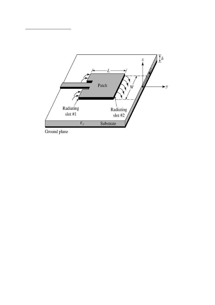
107
ﺎﺋﯿﺔــﺑﺮﮭﻜﻟا ﺔﺳﺪﻨﮭﻟا ﻢﺴﻗ ﻞــــﺻﻮﻤﻟا ﺔﻌﻣﺎﺟ
ﺎﻻتــﺼﺗﻻاو ﻚـــﯿﻧوﺮﺘﻜﻟﻻا عﺮـــــــــــــــﻓ
ﺎروديــﺒﻟا ﺪﻤﺤﻣ ﺪﯾﺆﻣ ناوﺮﻣ ﺐﻟﺎﻄﻟا داﺪﻋا
(MSA)
trip Antenna
Micros
Micro strip antenna consist of very thin ( t
≪
) metallic strip (patch) placed
a small fraction of a wavelength (
≪
) a bore a ground plane.
There are numerous substrack constants are usually in the range of
2.2 ≪
≪ 12
Advantages :-
1- light weight , low volume ,and thin profile configuration.
2- low falorieation cost.
3- the MSA support both the linear as well as the circular polarization.
4- MSA can be easily integrated with the microwave integrated circuits (MICs).
5- MSA can be mode compact for personal mobile communication.
6- capable of dual & triple frequency operations and provides flexibility to be
Constructed in any shape.
Disadvantages (Limitations):-
1- Narrow bandwidth.
2- Low gain.
3- Large ohmic loss in the feed structure of array.
4- Poor end-fine radiator.
5- Extraneous radiation from feeds and junctions.
6- Low power handling capability (
≃100 watt).
Microstrip Antenna
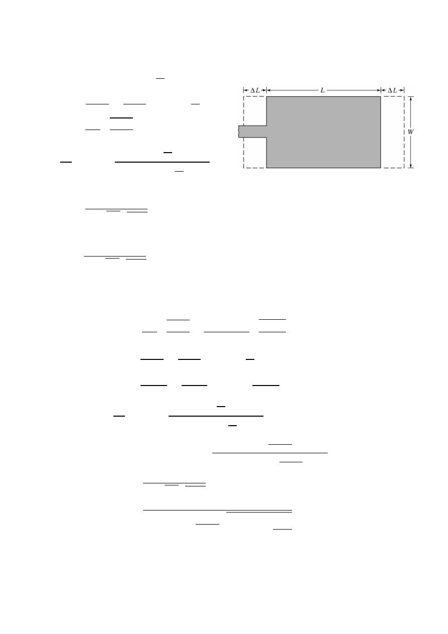
108
ﺎﺋﯿﺔــﺑﺮﮭﻜﻟا ﺔﺳﺪﻨﮭﻟا ﻢﺴﻗ ﻞــــﺻﻮﻤﻟا ﺔﻌﻣﺎﺟ
ﺎﻻتــﺼﺗﻻاو ﻚـــﯿﻧوﺮﺘﻜﻟﻻا عﺮـــــــــــــــﻓ
ﺎروديــﺒﻟا ﺪﻤﺤﻣ ﺪﯾﺆﻣ ناوﺮﻣ ﺐﻟﺎﻄﻟا داﺪﻋا
Design procedure for rectangular MSA specify
, , and
h
Determine W, L for
> 1
=
+
1
2
+
−1
2
1
+
12
/
=
2
2
+
1
∆
= 0.412
(
+
. )
+
.
(
−
.
)
+
.
=
+ 2∆
:
length effective
=
1
2
:
velocity
3 × 10 m/s
=
−
2∆
=
1
2
−
2∆
Ex:-
Design a rectangular microstrip antenna using a substrate with dielectric
constant of 2.2 , h = 0.1588 cm so as to resonate at 10 GHz.
The solution:-
=
2
2
+
1
=
3×10
8
2×10×10
9
2
2
.
2
+
1
= 0.01186 m= 1.186 cm
=
+
1
2
+
−1
2
1
+
12
/
=
2
.
2
+
1
2
+
2
.
2−1
2
1
+
12
.
.
/
= 1.972
∆
= 0.412
(
+
. )
+
.
(
−
.
)
+
.
∆
= 0.412
(
0.1588
)
(
1.972
+
0.3
)
1.186
0.1588
+
0.264
(
1.972
−
0.258
)
1.186
0.1588
+
0.8
= 0.081
=
1
2
=
1
2(10×10
9
)
√
1.972 4 ×10
−7
×
10−9
36
= 0.01068 m = 1.068 cm
=
−
2∆
= 1.068
−
2(
0.081
)
= 0.906 cm

109
ﺎﺋﯿﺔــﺑﺮﮭﻜﻟا ﺔﺳﺪﻨﮭﻟا ﻢﺴﻗ ﻞــــﺻﻮﻤﻟا ﺔﻌﻣﺎﺟ
ﺎﻻتــﺼﺗﻻاو ﻚـــﯿﻧوﺮﺘﻜﻟﻻا عﺮـــــــــــــــﻓ
ﺎروديــﺒﻟا ﺪﻤﺤﻣ ﺪﯾﺆﻣ ناوﺮﻣ ﺐﻟﺎﻄﻟا داﺪﻋا
Ex:-
Design a rectangular microstrip patch antenna whose center frequency
is dielectric 10 GHz. The dielectric constant of the substrate is 10.2 and
the height of the substrate is 0.127 cm. determine the physical dimensions
of the patch.
The solution:-
=
2
2
+
1
=
3×10
8
2×10×10
9
2
10
.
2
+
1
= 0.00634m= 0.634 cm
=
+
1
2
+
−1
2
1
+
12
/
=
10
.
2
+
1
2
+
10
.
2−1
2
1
+
12
0.127
0.634
/
= 8.635
∆
= 0.412
(
+
. )
+
.
(
−
.
)
+
.
∆
= 0.412 ℎ
(
+
0.3
)
ℎ
+
0.264
(
−
0.258
)
ℎ
+
0.8
∆
= 0.412
(
0.127
)
(
8.635
+
0.3
)
0.634
0.127
+
0.264
(
8.635
−
0.258
)
0.634
0.127
+
0.8
∆
= 0.0506
=
1
2
=
1
2 10×10
9
√
8.635 4 ×10
−7
×
10−9
36
= 0.0051 m = 0.51 cm
=
−
2∆
= 0.51
−
2(
0.0506
)
= 0.4088 cm
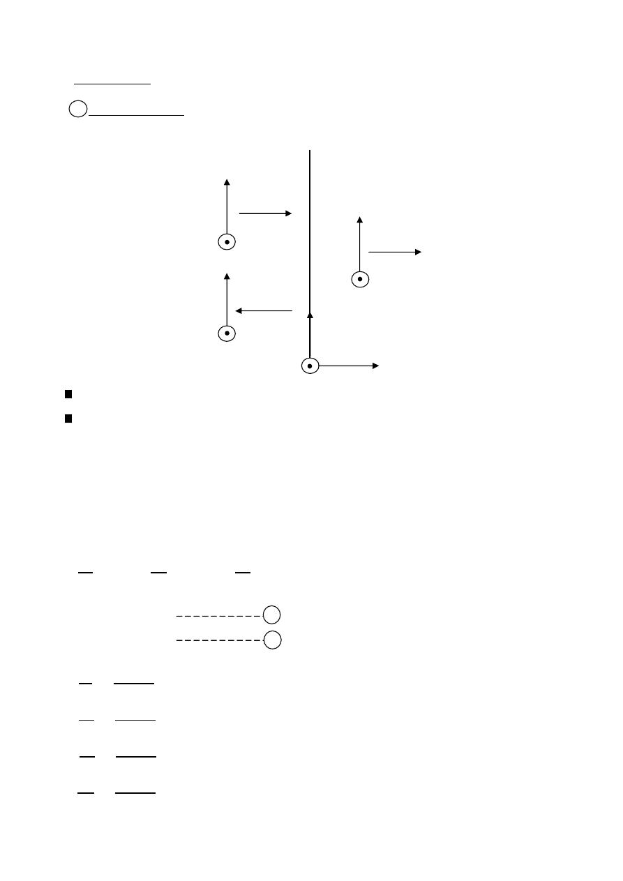
110
ﺎﺋﯿﺔــﺑﺮﮭﻜﻟا ﺔﺳﺪﻨﮭﻟا ﻢﺴﻗ ﻞــــﺻﻮﻤﻟا ﺔﻌﻣﺎﺟ
ﺎﻻتــﺼﺗﻻاو ﻚـــﯿﻧوﺮﺘﻜﻟﻻا عﺮـــــــــــــــﻓ
ﺎروديــﺒﻟا ﺪﻤﺤﻣ ﺪﯾﺆﻣ ناوﺮﻣ ﺐﻟﺎﻄﻟا داﺪﻋا
Plane wave
.
Normal incident
1
Consider a linearity polarized wave traveling in the positive X- direction.
The wave is incident normally on the boundary between two media.
E
i
: incident electric field component.
H
i
: incident magnetic field component.
E
t
: transmitted electric field component.
H
t
: transmitted magnetic field component.
E
r
: reflected electric field component.
H
r
: reflected magnetic field component.
=
1
,
= −
1
,
=
2
=
+
=
+
=
=
Transmitted coefficient
=
=
Reflection coefficient
=
=
Transmitted coefficient
=
=
Reflection coefficient
Interface
Medium 1
Medium 2
incident
reflected
wave
wave
wave
transmitted
,
,
,
,
,
,
y
Z
X
H
t
H
i
H
r
E
t
E
i
E
r
1
2

111
ﺎﺋﯿﺔــﺑﺮﮭﻜﻟا ﺔﺳﺪﻨﮭﻟا ﻢﺴﻗ ﻞــــﺻﻮﻤﻟا ﺔﻌﻣﺎﺟ
ﺎﻻتــﺼﺗﻻاو ﻚـــﯿﻧوﺮﺘﻜﻟﻻا عﺮـــــــــــــــﻓ
ﺎروديــﺒﻟا ﺪﻤﺤﻣ ﺪﯾﺆﻣ ناوﺮﻣ ﺐﻟﺎﻄﻟا داﺪﻋا
Ex:-
Prove that
1-
=
2-
=
3-
=
4-
=
The solution:-
1-
=
=
1 +
=
1 +
=
=
=
=
2-
=
=
−
1
=
−
1
=
(
)
=
=
=
3-
=
=
1 +
=
1 +
=
=
=
=
4-
=
=
−
1
=
−
1
=
(
)
=
=
=
The mediums:
1- For free space
= 0 ,
=
,
= 0 , = 120
2- For perfect dielectric
= 0 , =
,
= 0 , =
or
= 120
3- For conducting medium
≫ 1
⟹
≫
,
=
=
,
=
∠
45
4- For Partially conducting medium
=
2
1 +
2
− 1
=
2
1 +
2
+ 1
=
+

112
ﺎﺋﯿﺔــﺑﺮﮭﻜﻟا ﺔﺳﺪﻨﮭﻟا ﻢﺴﻗ ﻞــــﺻﻮﻤﻟا ﺔﻌﻣﺎﺟ
ﺎﻻتــﺼﺗﻻاو ﻚـــﯿﻧوﺮﺘﻜﻟﻻا عﺮـــــــــــــــﻓ
ﺎروديــﺒﻟا ﺪﻤﺤﻣ ﺪﯾﺆﻣ ناوﺮﻣ ﺐﻟﺎﻄﻟا داﺪﻋا
Ex:-
A plane 1 GHz traveling wave in air with peak electric field intensity of
1 V/m is incident normally on a large copper sheet. Find the average power
Absorbed by the sheet per square meter of area .
given
= 1 ,
= 1 ,
= 5.8 × 10 mho/m.
The solution:-
=
1
2
⃗
⊗
⃗
,
=
= 1 ,
=
= 120 ,
=
=
∠
45 =
2 ×10
9
×4 ×10
−7
5.8×10
7
∠
45 = 0.011667
∠
45
= (8.25 + 8.25)10 Ω
=
2
2
1
+
2
=
2×0.011667
∠
45
o
120 +8.25×10
−3
+ 8.25×10
−3
× 1 =
0.023334
∠
45
o
377+ 8.25×10
−3
=
0.023334
∠
45
o
377
∠
0.00125
o
= 61.9
∠
45
o
V/m
=
2
⟹
=
2
=
61.9
×
10
−6
∠
45
o
0.011667
∠
45
o
= 5.3 × 10 A/m
=
1
2
⃗
⊗
⃗
=
1
2
[61.9
×
10
cos (
45
)
× 5.3 × 10 ]
= 1.16 × 10
watt
/m
or
=
1
2
⃗
⊗
⃗
⟹
=
1
2
[
]
=
1
2
[8.25 × 10
× (5.3 × 10 ) ]
= 1.16 × 10
watt
/m
or
=
1
2
⃗
⊗
⃗
⟹
=
1
2
2
2
=
1
2
61.9
×
10
−6
∠
45
o 2
0.011667
∠
45
o
=
1
2
61.9
×
10
−6 2
∠
90
o
0.011667
∠
45
o
=
1
2
61.9
×
10
−6 2
0.011667
∠
(90 − 45 )
=
1
2
61.9
×
10
−6 2
0.011667
∠
45
=
1
2
61.9
×
10
−6 2
0.011667
45
= 1.16 × 10
watt
/m
*
*
*
*
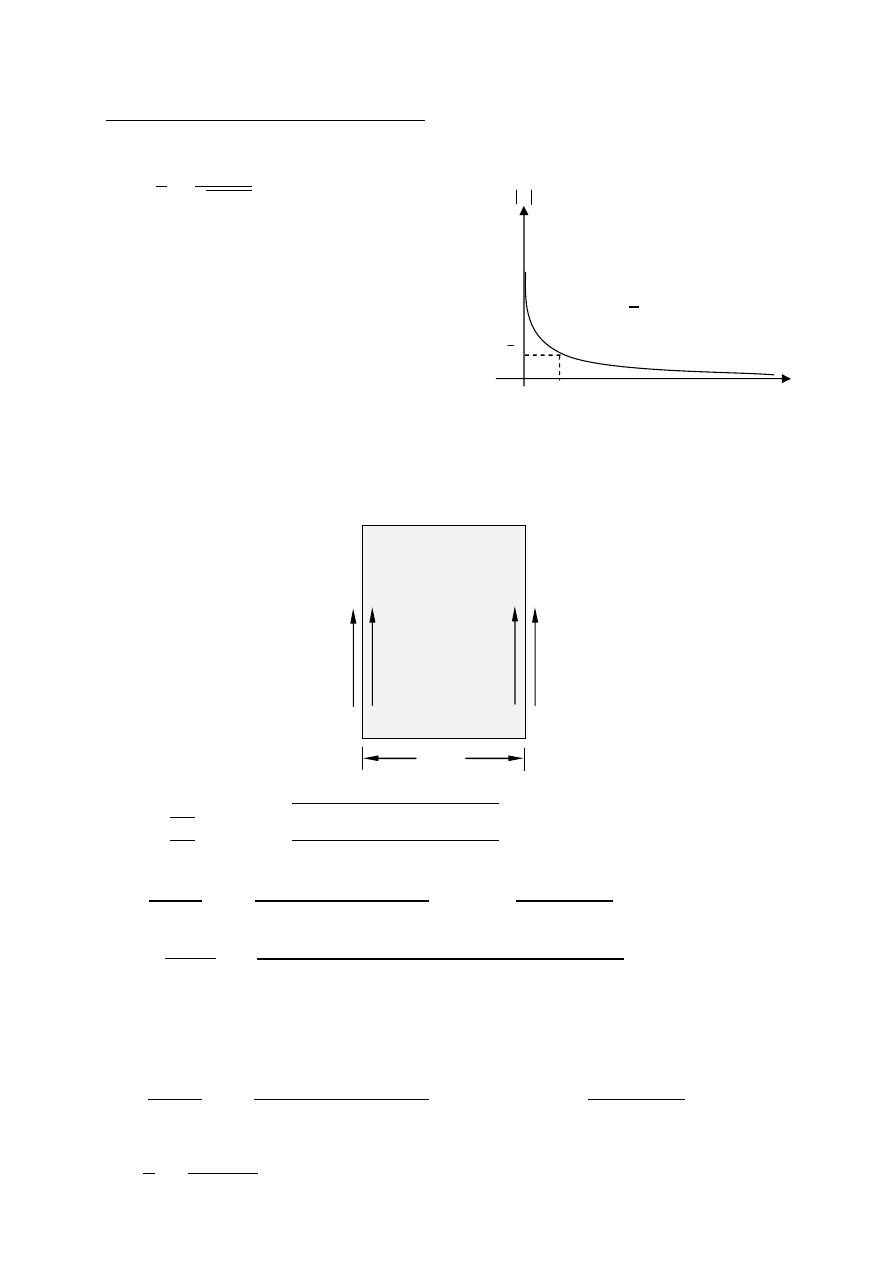
113
ﺎﺋﯿﺔــﺑﺮﮭﻜﻟا ﺔﺳﺪﻨﮭﻟا ﻢﺴﻗ ﻞــــﺻﻮﻤﻟا ﺔﻌﻣﺎﺟ
ﺎﻻتــﺼﺗﻻاو ﻚـــﯿﻧوﺮﺘﻜﻟﻻا عﺮـــــــــــــــﻓ
ﺎروديــﺒﻟا ﺪﻤﺤﻣ ﺪﯾﺆﻣ ناوﺮﻣ ﺐﻟﺎﻄﻟا داﺪﻋا
penetration)
Skin depth (depth of
The skin depth is defined to be the distance after which | | has decreased to
=
1
=
1
(m)
The E & H traveling waves in conducting
medium are attenuated by the factor
=
as they advance along a long Z.
=
this attenuation s so rapid that the waves
may be considered to be zero after only
a few millimeter of travel.
Ex:-
A traveling E-field in free space of amplitude 100 V/m strikes a sheet of
silver of thickness 5 m as shown in figure below. assuming
= 61.7 MS/m
and a frequency of 200 MHz. find the amplitude
,
,
&
.
The solution:-
= 100 ,
=
,
=
,
=
=
∠
45 =
2 ×200×10
6
×4 ×10
−7
61.7×10
6
∠
45 = 5.05 × 10
∠
45 Ω
=
2
2
1
+
2
=
2×0.00505
∠
45
o
120 +0.707+ 0.707
× 100 =
1.01
∠
45
o
377.7
∠
0.1
o
= 2.67 × 10
∠
44.9 V/m
=
= √ × 200 × 10 × 4 × 10
× 61.7 × 10 = 2.2 × 10 neper/m
=
= 2.67 × 10
(2.2×10
5
×5×10
−6
)
= 8.88 × 10 V/m
=
2
3
2
+
3
=
2×120
120 +0.707+ 0.707
× 8.88 × 10
=
0.6695
377.7
∠
0.1
o
= 1.77 × 10
∠
−0.1 V/m
=
1
=
1
2.2×10
5
= 4.5 m
1
e
medium 2
silver
E
2
E
3
medium 1
medium 3
5µm
Free space
Free space
=1
=1
=1
=1
= 0
= 0
= 0
= 0
=120
π
=120
π
E
1
E
4
Z
E

114
ﺎﺋﯿﺔــﺑﺮﮭﻜﻟا ﺔﺳﺪﻨﮭﻟا ﻢﺴﻗ ﻞــــﺻﻮﻤﻟا ﺔﻌﻣﺎﺟ
ﺎﻻتــﺼﺗﻻاو ﻚـــﯿﻧوﺮﺘﻜﻟﻻا عﺮـــــــــــــــﻓ
ﺎروديــﺒﻟا ﺪﻤﺤﻣ ﺪﯾﺆﻣ ناوﺮﻣ ﺐﻟﺎﻄﻟا داﺪﻋا
Ex:-
In a partially conducting medium
= 18.5 ,
= 800 , and
= 1 mho/m
Find , , , and the velocity for a frequency of
10 Hz
Determine ⃗
( , ) given ⃗( , ) = 50
cos (
−
) ⃗ V/m.
The solution:-
=
2
1 +
2
− 1
= 2 × 10
⎷
⃓
⃓
⃓
⃓
⃓
⃓
⃓
⃓
4 ×10
−7
×800×
10
−9
36
×18.5
2
⎝
⎜
⎛
1 +
1
2 ×10
9
×
10
−9
36
×18.5
2
− 1
⎠
⎟
⎞
= 1132.6646 neper/m
=
2
1 +
2
+ 1
= 2 × 10
⎷
⃓
⃓
⃓
⃓
⃓
⃓
⃓
⃓
4 ×10
−7
×800×
10−9
36
×18.5
2
⎝
⎜
⎛
1 +
1
2 ×10
9
×
10
−9
36
×18.5
2
+ 1
⎠
⎟
⎞
= 2788.36 rad/m
=
+
=
2 ×10
9
×4 ×10
−7
×800
1+ 2 ×10
9
×
10
−9
36
×18.5
=
6310144
1+ 1.0277
=
6310144
∠
90
o
1.434
∠
45.8
o
=
6310144
∠
90
o
−∠
45.8
o
1.434
= √4400379.358
∠
44.2 = 2098
∠
22.1 Ω
=
=
2 ×10
9
2788.36
= 2.25 Mmps
⃗(
, ) = 50
1132.6646
cos (2 × 10
− 2788.36 ) ⃗
⃗(
, ) =
⃗(
,
)
⃗(
, ) =
50
120
1132.6646
cos (2 × 10
− 2788.36 ) ⃗
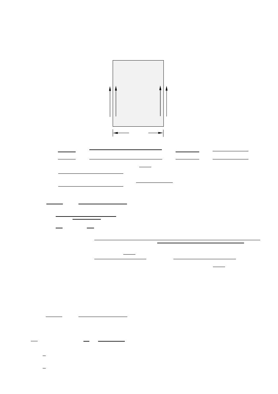
115
ﺎﺋﯿﺔــﺑﺮﮭﻜﻟا ﺔﺳﺪﻨﮭﻟا ﻢﺴﻗ ﻞــــﺻﻮﻤﻟا ﺔﻌﻣﺎﺟ
ﺎﻻتــﺼﺗﻻاو ﻚـــﯿﻧوﺮﺘﻜﻟﻻا عﺮـــــــــــــــﻓ
ﺎروديــﺒﻟا ﺪﻤﺤﻣ ﺪﯾﺆﻣ ناوﺮﻣ ﺐﻟﺎﻄﻟا داﺪﻋا
Ex:-
A traveling E-field in free space strikes a partially conducting medium
as shown in figure below, given a frequency of 500 MHz and
= 100 V/m
determine
&
& .
The solution:-
= 100 ,
=
,
=
,
=
=
+
=
2 ×500×10
6
×4 ×10
−7
1+ 2 ×500×10
6
×
10−9
36
×55
=
3943.84
1+ 1.53
=
3943.84
∠
90
o
1.83
∠
56.8
o
=
3943.84
∠
90
o
−∠
56.8
o
1.83
= √2155
∠
33.2 = 46.4
∠
16.6 Ω
=
2
2
1
+
2
=
2×46.4
∠
16.6
o
120 +46.4
∠
16.6
o
× 100 = 22
∠
14.795 V/m
=
2
1 +
2
− 1
= 2 × 500 × 10
⎷
⃓
⃓
⃓
⃓
⃓
⃓
⃓
⃓
4 ×10
−7
×
10−9
36
×55
2
⎝
⎜
⎛
1 +
1
2 ×500×10
6
×
10−9
36
×55
2
− 1
⎠
⎟
⎞
= 24.26 neper/m
=
= 22
(24.26×30×10
−3
)
= 10.6 V/m
=
2
3
2
+
3
=
2×120
120 +46.4
∠
16.6
o
× 10.6
= 19
∠
−1.8 V/m
=
3
⟹
=
3
=
19
∠
−1.8
o
120
= 0.05
∠
−1.8 A/m
=
1
2
⃗
⊗
⃗
=
1
2
[19
cos (−
1.8
)
× 0.05
cos (
−1.8
)
] = 0.47
watt
/m
medium 2
E
2
E
3
medium 1
medium 3
30mm
Free space
Free space
=1
=1
=1
=1
= 1
E
i
E
t
=1
=1
*
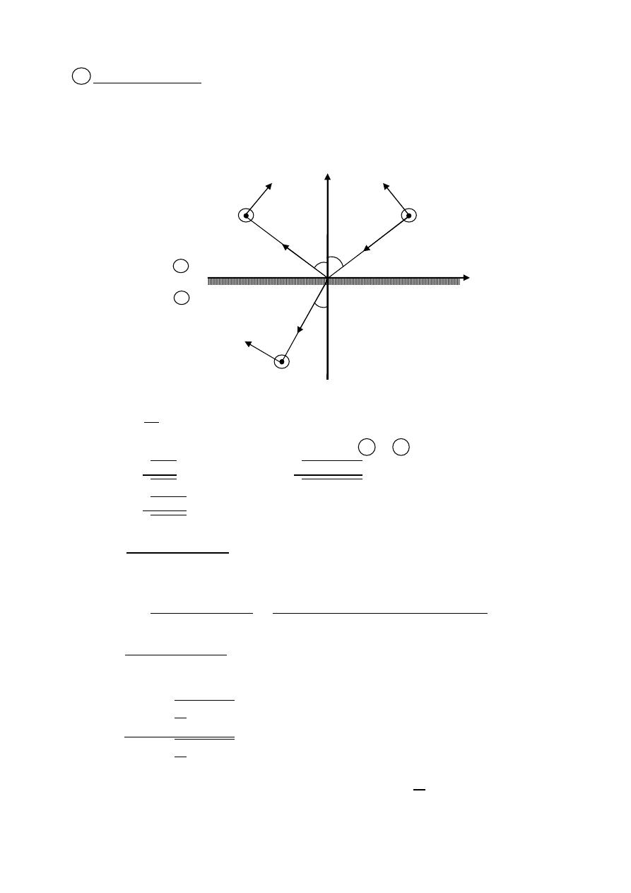
116
ﺎﺋﯿﺔــﺑﺮﮭﻜﻟا ﺔﺳﺪﻨﮭﻟا ﻢﺴﻗ ﻞــــﺻﻮﻤﻟا ﺔﻌﻣﺎﺟ
ﺎﻻتــﺼﺗﻻاو ﻚـــﯿﻧوﺮﺘﻜﻟﻻا عﺮـــــــــــــــﻓ
ﺎروديــﺒﻟا ﺪﻤﺤﻣ ﺪﯾﺆﻣ ناوﺮﻣ ﺐﻟﺎﻄﻟا داﺪﻋا
.
Oblique incidence
1- Perpendicular Polarization.
In this case the electric field is perpendicular to the plane of incidence
(xy-plane).
In this case
1-
=
2-
=
1
2
(Snell's Law).
&
are indexes of refraction of medium 1 & 2
=
1 1
2 2
⟹
=
1
1
2
2
=
1
1
2
2
=
2
−
1
2
+
1
= 1 +
= 1 +
2
−
1
2
+
1
=
2
+
1
+
2
−
1
2
+
1
=
2
2
2
+
1
if both media are lossless non magnetic dielectrics
=
−
2
1
−
2
+
2
1
−
2
if
2
>
1
⟹
will be real if
1
>
2
&
>
⟹
becomes
|
| = 1
complex &
2
x
y
E
r
E
i
H
i
H
r
θ
i
θ
r
θ
t
E
t
H
t
reflection
incident
transmitted
medium 1
,
,
,
,
,
,
,
,
medium 2
θ
i
:
angle of incidence
θ
r
:
angle of reflection
θ
t
:
angle of transmission
n
:
refraction index
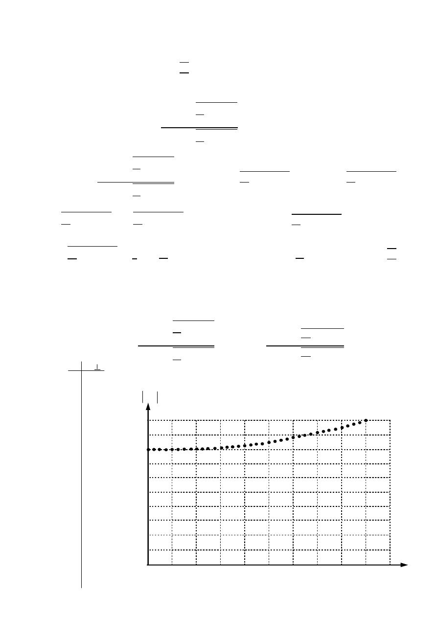
117
ﺎﺋﯿﺔــﺑﺮﮭﻜﻟا ﺔﺳﺪﻨﮭﻟا ﻢﺴﻗ ﻞــــﺻﻮﻤﻟا ﺔﻌﻣﺎﺟ
ﺎﻻتــﺼﺗﻻاو ﻚـــﯿﻧوﺮﺘﻜﻟﻻا عﺮـــــــــــــــﻓ
ﺎروديــﺒﻟا ﺪﻤﺤﻣ ﺪﯾﺆﻣ ناوﺮﻣ ﺐﻟﺎﻄﻟا داﺪﻋا
Critical angle :- is the incident angle for which
= 1∠0
=
−1
2
1
Ex:-
Drive an expression for the critical angle.
The solution:-
=
−
2
1
−
2
+
2
1
−
2
1∠0 =
−
2
1
−
2
+
2
1
−
2
⟹
+
2
1
−
=
−
2
1
−
−
2
+
−
2
=
−
⟹
2
2
1
−
= 0
−
2
=
0
2
⟹
2
1
−
2
= 0
⟹
2
=
2
1
⟹
=
−1
2
1
Ex:-
A wave is incident from air onto distilled water
= 81 , Plot the magnitude
of the reflection coefficient as a function of incident angle for perpendicular
polarization.
The solution:-
=
−
2
1
−
2
+
2
1
−
2
⟹
=
−
81
1
−
2
+
81
1
−
2
0° 10° 20° 30° 40° 50° 60° 70° 80° 90°
0
0
.0.1
0.4
0.3
0.6
0.5
0.7
0.8
0.9
1
0 0.8
5° 0.8006
10° 0.802
15° 0.806
20° 0.81
25° 0.8168
30° 0.824
35° 0.832
40° 0.842
45° 0.853
50° 0.866
55° 0.879
60° 0.894
65° 0.909
70° 0.926
75° 0.944
80° 0.961
85° 0.98
90° 1
θ
K
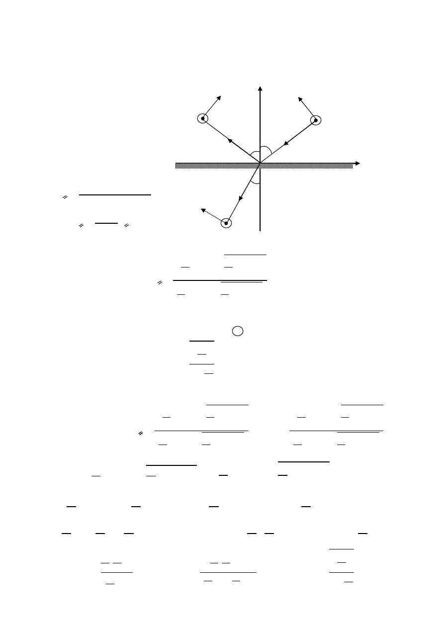
118
ﺎﺋﯿﺔــﺑﺮﮭﻜﻟا ﺔﺳﺪﻨﮭﻟا ﻢﺴﻗ ﻞــــﺻﻮﻤﻟا ﺔﻌﻣﺎﺟ
ﺎﻻتــﺼﺗﻻاو ﻚـــﯿﻧوﺮﺘﻜﻟﻻا عﺮـــــــــــــــﻓ
ﺎروديــﺒﻟا ﺪﻤﺤﻣ ﺪﯾﺆﻣ ناوﺮﻣ ﺐﻟﺎﻄﻟا داﺪﻋا
2- Parallel polarization.
In this case the electric field is parallel to the plane of incidence
(xy-plane)
=
2
−
1
2
+
1
1 + =
For lossless non-magnetic dielectrics the reflection coefficient for parallel
=
−
2
1
+
2
1
−
2
2
1
+
2
1
−
2
Brewster angle:- is the incident angle for which
= 0 and the wave is to tally
transmitted into medium 2
=
−1
2
1
1+
.
2
1
Ex:-
Drive an expression for the critical angle.
The solution:-
=
−
2
1
+
2
1
−
2
2
1
+
2
1
−
2
⟹
0 =
−
2
1
+
2
1
−
2
2
1
+
2
1
−
2
0 = −
2
1
+
2
1
−
⟹
2
1
=
2
1
−
2
2
=
−
2
⟹
(
1 −
2
)
=
−
2
−
=
2
−
2
⟹
− 1
=
2
− 1
=
2
1
2
1
−
2
1
2
⟹
=
2
1
2
1
−1
2
1
−1
2
1
+1
⟹
=
2
1
1+
.
2
1
Polarization becomes
medium 1
medium 2
θ
t
E
t
H
t
transmitted
θ
i
θ
r
H
r
H
i
E
r
E
i
y
x
incident
reflection
,
,
,
,
,
,
,
,
θ
i
:
angle of incidence
θ
r
:
angle of reflection
θ
t
:
angle of transmission
n
:
refraction index
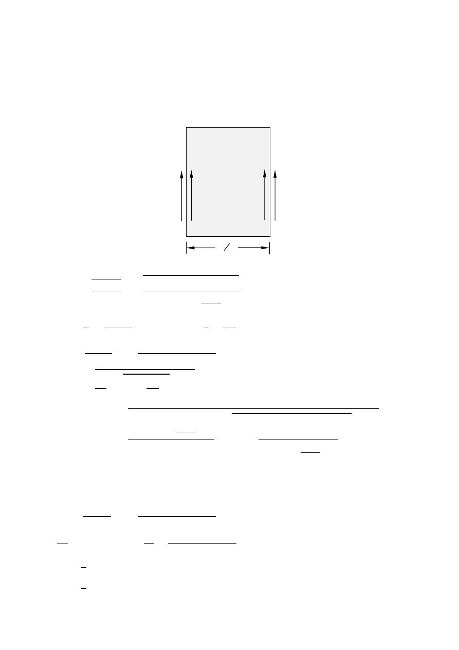
119
ﺎﺋﯿﺔــﺑﺮﮭﻜﻟا ﺔﺳﺪﻨﮭﻟا ﻢﺴﻗ ﻞــــﺻﻮﻤﻟا ﺔﻌﻣﺎﺟ
ﺎﻻتــﺼﺗﻻاو ﻚـــﯿﻧوﺮﺘﻜﻟﻻا عﺮـــــــــــــــﻓ
ﺎروديــﺒﻟا ﺪﻤﺤﻣ ﺪﯾﺆﻣ ناوﺮﻣ ﺐﻟﺎﻄﻟا داﺪﻋا
Ex:-
A plane 1 GHz traveling wave in air is incident normally ,
= 1 V/m
upon a sea water (
= 81 ,
= 1 , and = 5 mho/m) .
1- Calculate the magnitude of the electric field strength at
/4 away
from the interface.
2- Determine the average power density.
The solution:-
= 1 ,
=
,
=
,
=
1-
=
+
=
2 ×10
9
×4 ×10
−7
5+ 2 ×10
9
×
10−9
36
×81
= 34.26
∠
24 Ω
=
=
3×10
8
10
9
= 0.3m , =
4
=
0.3
4
= 0.075m
=
2
2
1
+
2
=
2×34.26
∠
24
o
120 +34.26
∠
24
o
× 1 = 0.1677
∠
22 V/m
=
2
1 +
2
− 1
= 2 × 10
⎷
⃓
⃓
⃓
⃓
⃓
⃓
⃓
⃓
4 ×10
−7
×
10−9
36
×81
2
⎝
⎜
⎛
1 +
1
2 ×10
9
×
10
−9
36
×81
2
− 1
⎠
⎟
⎞
= 20.8 neper/m
=
= 0.1677
(20.8×75×10
−3
)
= 35.24 mV/m
=
2
3
2
+
3
=
2×120
120 +34.26
∠
24
o
× 35.24 × 10
= 0.065
∠
−1.955 V/m
=
3
⟹
=
3
=
0.065
∠
−1.955
o
120
= 1.724 × 10
∠
−1.955 A/m
=
1
2
⃗
⊗
⃗
=
1
2
[0.065
cos (−
1.955
)
× 1.724 × 10
cos (
−1.955
)
]
= 5.6
watt
/m
*
medium 2
E
2
E
3
medium 1
medium 3
Free space
Free space
=1
=1
=1
=1
= 5
E
i
E
t
= 81
=1
4

120
ﺎﺋﯿﺔــﺑﺮﮭﻜﻟا ﺔﺳﺪﻨﮭﻟا ﻢﺴﻗ ﻞــــﺻﻮﻤﻟا ﺔﻌﻣﺎﺟ
ﺎﻻتــﺼﺗﻻاو ﻚـــﯿﻧوﺮﺘﻜﻟﻻا عﺮـــــــــــــــﻓ
ﺎروديــﺒﻟا ﺪﻤﺤﻣ ﺪﯾﺆﻣ ناوﺮﻣ ﺐﻟﺎﻄﻟا داﺪﻋا
Ex:-
A 500 MHz traveling wave in free space strikes a partially conducting
Medium (
= 55 ,
= 1 , and = 1 mho/m) if
= 1 V/m and the
Incident angle is
45 , Determine
1- , , , and for the partially conducting medium.
2- The average power absorbed by the medium for square meter of area.
The solution:-
= 1 , F = 500 MHz ,
= 55 ,
= 1 , and = 1 mho/m
1-
=
2
1 +
2
− 1
= 2 × 500 × 10
⎷
⃓
⃓
⃓
⃓
⃓
⃓
⃓
⃓
4 ×10
−7
×
10−9
36
×55
2
⎝
⎜
⎛
1 +
1
2 ×500×10
6
×
10−9
36
×55
2
− 1
⎠
⎟
⎞
= 24.26 neper/m
=
2
1 +
2
+ 1
= 2 × 500 × 10
⎷
⃓
⃓
⃓
⃓
⃓
⃓
⃓
⃓
4 ×10
−7
×
10−9
36
×55
2
⎝
⎜
⎛
1 +
1
2 ×500×10
6
×
10−9
36
×55
2
+ 1
⎠
⎟
⎞
= 81.36 rad/m
=
+
=
2 ×500×10
6
×4 ×10
−7
1+ 2 ×500×10
6
×
10−9
36
×55
=
3943.84
1+ 1.53
=
3943.84
∠
90
o
1.83
∠
56.8
o
=
3943.84
∠
90
o
−∠
56.8
o
1.83
= √2155
∠
33.2 = 46.4
∠
16.6 Ω
=
=
2 ×500×10
6
81.36
= 38.6 Mmps
2-
=
1
1
2
2
⟹
=
1
55
45
⟹
= 5.47
=
2
−
1
2
+
1
=
46.4
∠
16.6
o
cos 45 −120 cos (5.47)
46.4
∠
16.6
o
cos 45 +120 cos(5.47)
= 0.844∠177
= 1 +
= 1 + 0.844∠177 = 0.163∠15.7
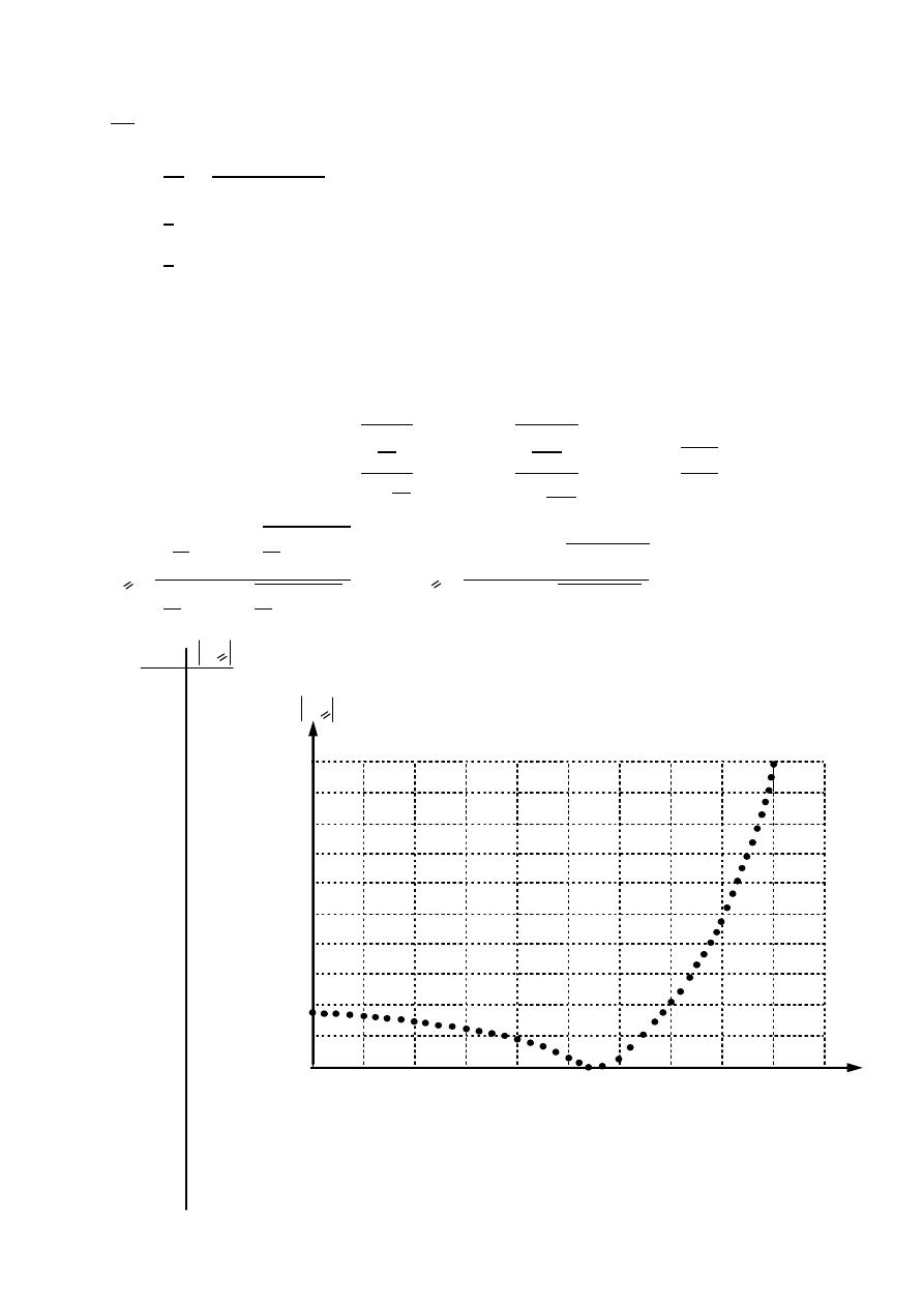
121
ﺎﺋﯿﺔــﺑﺮﮭﻜﻟا ﺔﺳﺪﻨﮭﻟا ﻢﺴﻗ ﻞــــﺻﻮﻤﻟا ﺔﻌﻣﺎﺟ
ﺎﻻتــﺼﺗﻻاو ﻚـــﯿﻧوﺮﺘﻜﻟﻻا عﺮـــــــــــــــﻓ
ﺎروديــﺒﻟا ﺪﻤﺤﻣ ﺪﯾﺆﻣ ناوﺮﻣ ﺐﻟﺎﻄﻟا داﺪﻋا
⊥
=
⊥
⟹
=
⟹
= 0.163∠15.7 × 1 = 0.163∠15.7
V/m
=
2
=
0.163∠15.7
o
46.4
∠
16.6
o
= 3.5 × 10 ∠−0.9 A/m
=
1
2
⃗
⊗
⃗
=
1
2
[0.163
cos (
15.7
)
× 3.5 × 10
cos (
−0.9
)
]
= 275
watt
/m
Ex:-
Plot the magnitude of the reflection coefficient as a function of incident
angle (assume parallel polarization and
= 2
).
The solution:-
=
−1
2
1
1+
.
2
1
=
−1
2
1
1
1+
.
2
1
1
=
−1
2
1+2
= 54.7
=
−
2
1
+
2
1
−
2
2
1
+
2
1
−
2
⟹
=
−2
+
2−
2
2
+
2−
2
*
0 0.171
5° 0.17
10° 0.167
15° 0.163
20° 0.155
25° 0.146
30° 0.133
35° 0.118
40° 0.097
45° 0.071
50° 0.039
55° 0.0024
60° 0.055
65° 0.124
70° 0.214
75° 0.332
80° 0.491
85° 0.704
90° 1
0° 10° 20° 30° 40° 50° 60° 70° 80° 90°
0
0.2
0.1
0.4
0.3
0.6
0.5
0.7
0.8
0.9
1
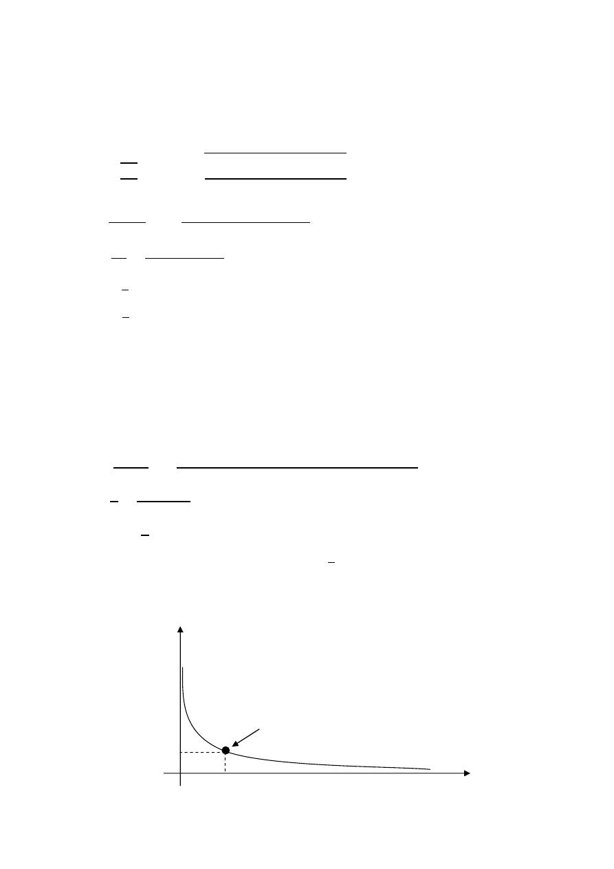
122
ﺎﺋﯿﺔــﺑﺮﮭﻜﻟا ﺔﺳﺪﻨﮭﻟا ﻢﺴﻗ ﻞــــﺻﻮﻤﻟا ﺔﻌﻣﺎﺟ
ﺎﻻتــﺼﺗﻻاو ﻚـــﯿﻧوﺮﺘﻜﻟﻻا عﺮـــــــــــــــﻓ
ﺎروديــﺒﻟا ﺪﻤﺤﻣ ﺪﯾﺆﻣ ناوﺮﻣ ﺐﻟﺎﻄﻟا داﺪﻋا
Ex:-
A 200 MHz wave in free space with peak amplitude of 100 V/m is incident
Normally on a large sheet of copper of 20 m thickness sketch the average
Power density versus copper thickness . assume
= 58 Mmho/m
The solution:- f = 200 MHz ,
= 100 V/m ,
= 120
=
∠
45 =
2 ×200×10
6
×4 ×10
−7
58×10
6
∠
45 = 5.2 × 10
∠
45 Ω
=
2
2
1
+
2
=
2×5.2×10
−3
∠
45
o
120 +5.2×10
−3
∠
45
o
× 100 = 2.75 × 10
∠
45 V/m
=
2
2
=
0.00275
∠
45
o
0.0052
∠
45
o
= 0.53 A/m
=
1
2
⃗
⊗
⃗
=
1
2
[0.00275
cos (
45
)
× 0.53]
= 515.3
watt
/m
This is max absorbed average power by the sheet & it will be attenuated by
The factor (
)
( )
=
( )
=
( ) =
=
= √ × 200 × 10 × 4 × 10
× 58 × 10 = 214 × 10 neper/m
=
1
=
1
214×10
3
= 4.67 m
=
=
1
( ) =
= 515.3 × 10
−2
1
= 515.3 × 10
−2
= 69.7 V/m
*
P
(
z
)
avg
z
4.67µm
515.3µ
69.7µ
P
e
o
-2

123
ﺎﺋﯿﺔــﺑﺮﮭﻜﻟا ﺔﺳﺪﻨﮭﻟا ﻢﺴﻗ ﻞــــﺻﻮﻤﻟا ﺔﻌﻣﺎﺟ
ﺎﻻتــﺼﺗﻻاو ﻚـــﯿﻧوﺮﺘﻜﻟﻻا عﺮـــــــــــــــﻓ
ﺎروديــﺒﻟا ﺪﻤﺤﻣ ﺪﯾﺆﻣ ناوﺮﻣ ﺐﻟﺎﻄﻟا داﺪﻋا
Ex:-
Distilled water is a dielectric having the consists
= 81 ,
= 1
If a wave is incident from water onto water-air interface , calculate
The magnitude of the electric field strength in the air at the interface
Assume the incident
= 1 V/m and the incident angle is 45°.
The solution:-
=
−
2
1
−
2
+
2
1
−
2
=
45−
1
81
−
2
45
45+
1
81
−
2
45
= 0.0125 − 0.999
= 1 +
= 1 + 0.0125 − 0.999
= 1.0125 − 0.999 = 1.0125 − 0.999 = 1.422∠ − 44.6
=
⊥
⟹
=
⊥
= 1.422 × 1
= 1.422 V/m
Ex:-
Distilled water is a dielectric having the consists
= 81 ,
= 1
If a wave is incident from air onto air-water interface , calculate
The magnitude of the magnetic field strength in the water at the interface
Assume the incident
= 1 V/m and the incident angle is 45° with parallel
polarization.
The solution:-
=
−
2
1
+
2
1
−
2
2
1
+
2
1
−
2
=
−81×
45+ 81
−
2
45
81×
45+ 81
−
2
45
= −0.729
=
1
1
2
2
=
1
81
45
⟹
= 4.5
1 + =
1 − 0.729 =
4.5
45
⟹
= 0.1922
=
⟹
=
= 0.1922 × 1 = 0.1922 V/m
=
2
=
0.1922
120
1
81
= 4.588 mA/m
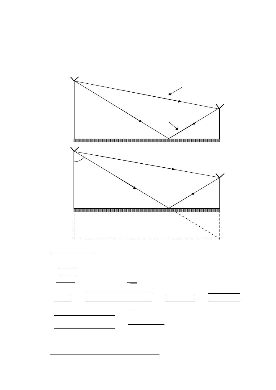
124
ﺎﺋﯿﺔــﺑﺮﮭﻜﻟا ﺔﺳﺪﻨﮭﻟا ﻢﺴﻗ ﻞــــﺻﻮﻤﻟا ﺔﻌﻣﺎﺟ
ﺎﻻتــﺼﺗﻻاو ﻚـــﯿﻧوﺮﺘﻜﻟﻻا عﺮـــــــــــــــﻓ
ﺎروديــﺒﻟا ﺪﻤﺤﻣ ﺪﯾﺆﻣ ناوﺮﻣ ﺐﻟﺎﻄﻟا داﺪﻋا
Ex:-
For the two antenna system shown in the figure , one antenna is transmitting
a 1GHz signal 30m above moist earth , the receiving antenna is 16 Km away
and 10m above moist earth (
= 12 , = 0.02 mho/m) show that the signal
is almost perfectly reflected by the earth to the receiver.
(assume perpendicular polarization).
The solution:-
=
2
−
1
2
+
1
,
=
,
=
=
16000
40
⟹
= 89.85
=
1
1
2
2
⟹
=
1
12
89.85
⟹
= 16.7
=
+
=
2 ×10
9
×4 ×10
−7
0.02+ 2 ×10
9
×
10
−9
36
×12
=
7895.7
0.02+ 0.67
=
7895.7
∠
90
o
0.67
∠
88.3
o
=
7895.7
∠
90
o
−∠
88.3
o
0.67
= √11785
∠
1.7 = 108.56
∠
0.85 Ω
= 108.55 + 1.61
=
108.56
∠
0.85
o
cos 89.85 −120 cos (16.7)
108.56
∠
0.85
o
cos 89.85 +120 cos(16.7)
= 1∠180
16000m
10m
30m
30m
10m
10m
10m
16000m
i
θ
Directed path
Reflected path
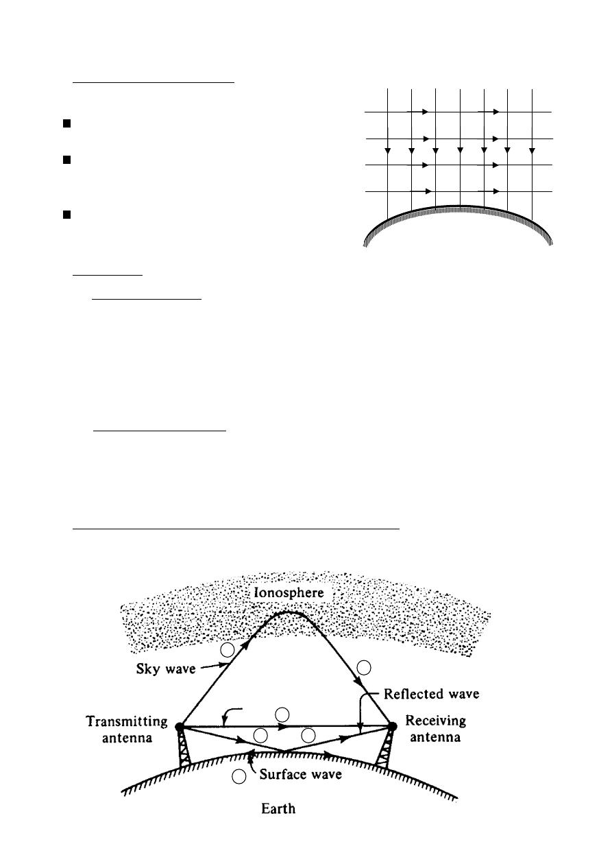
125
ﺎﺋﯿﺔــﺑﺮﮭﻜﻟا ﺔﺳﺪﻨﮭﻟا ﻢﺴﻗ ﻞــــﺻﻮﻤﻟا ﺔﻌﻣﺎﺟ
ﺎﻻتــﺼﺗﻻاو ﻚـــﯿﻧوﺮﺘﻜﻟﻻا عﺮـــــــــــــــﻓ
ﺎروديــﺒﻟا ﺪﻤﺤﻣ ﺪﯾﺆﻣ ناوﺮﻣ ﺐﻟﺎﻄﻟا داﺪﻋا
Radio wave Propagation
Characteristic of electromagnetic waves
Radio waves is composed of moving field of
electric & magnetic force.
The lines of force in the electric & magnetic
fields are at right angles and perpendicular
to the direction of travel.
The plane containing the lines of electric and
magnetic force is called wave front.
-
:
Polarization
:
Linear polarization
-
A
The polarization of an electromagnetic waves is the direction of the lines of force
in the electric field.
1- if the electric lines perpendicular to earth's surface
∴ the wave is said to be vertically polarized.
2- if the electric lines parallel to earth's surface
∴ the wave is said to be horizontally polarized.
:
inear polarization
Non l
-
B
1- if the direction of the lines of force in electric field is elliptical
∴ the wave is said to elliptically polarized.
2- circular polarization is a special case of elliptical polarization.
Propagation of radio waves at different frequency
The modes of propagation at different frequencies
earth surface
E
H
H
4
4
Direct wave
4
3
2
2
1
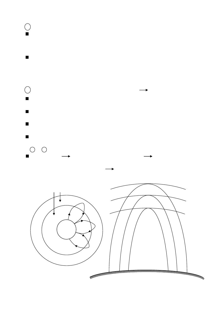
126
ﺎﺋﯿﺔــﺑﺮﮭﻜﻟا ﺔﺳﺪﻨﮭﻟا ﻢﺴﻗ ﻞــــﺻﻮﻤﻟا ﺔﻌﻣﺎﺟ
ﺎﻻتــﺼﺗﻻاو ﻚـــﯿﻧوﺮﺘﻜﻟﻻا عﺮـــــــــــــــﻓ
ﺎروديــﺒﻟا ﺪﻤﺤﻣ ﺪﯾﺆﻣ ناوﺮﻣ ﺐﻟﺎﻄﻟا داﺪﻋا
1
Ground wave propagation (up to 2 MHz).
electromagnetic waves are propagated.
a- closed to earth's surface.
b- following the curvature of the globe due to diffraction.
Problems: the wave suffers varying amount of attenuation according to its nature
Surface irregularities , permittivity , conductivity.
Earth attenuation increase with increase frequency
this mode of propagation is suitable for medium waves (MW) up to 2 MHz.
2
Sky (ion sphere or short) wave propagation (2 MHz 30 MHz).
Radio waves is reflected back to the earth from ionized in the upper at mosphere
(called ion sphere).
Beyond 30 MHz the wave is penetrate the ion sphere (not reflected)
this mode of propagation is suitable for short waves (2 MHz 30 MHz).
This mode of propagation is useful for long communication along the globe
through multiple reflections.
For single reflection radio wave can cover 4000 Km distance problem
(fading) because of different paths
3 & 4 ( directed , reflected )
in troposphere space wave propagation ( 30 MHz on ward )
space wave propagation is chief source of VHF communication
(television & radar) (VHF : 30 MHz 300 MHz).
F
3
F
2
F
1
F
3
> F
2
> F
1
ion sphere
Earth's surface
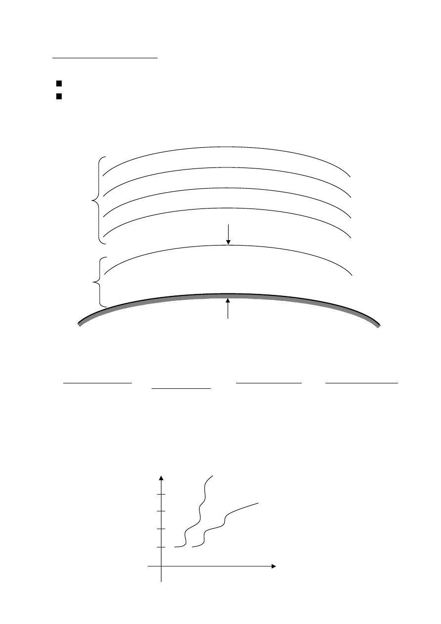
127
ﺎﺋﯿﺔــﺑﺮﮭﻜﻟا ﺔﺳﺪﻨﮭﻟا ﻢﺴﻗ ﻞــــﺻﻮﻤﻟا ﺔﻌﻣﺎﺟ
ﺎﻻتــﺼﺗﻻاو ﻚـــﯿﻧوﺮﺘﻜﻟﻻا عﺮـــــــــــــــﻓ
ﺎروديــﺒﻟا ﺪﻤﺤﻣ ﺪﯾﺆﻣ ناوﺮﻣ ﺐﻟﺎﻄﻟا داﺪﻋا
Structure of Atmosphere
1- Structure of troposphere .
Extending from the surface of earth up to a height of 10 Km.
Percentage of gas components does not vary with height.
2- structure ion sphere.
critical frequency
electron density
Ion sphere layer
D-layer
50 − 90 Km 10 − 10 /
100 KHz
110 Km 10 − 4.5 × 10 /
(3 − 5) MHz
E-layer
220 Km 2 × 10 − 4.5 × 10 /
(5 − 7) MHz
F
1
-layer
250 Km 3 × 10 − 2 × 10 /
10 MHz
F
2
-layer
250 Km
220 Km
110 Km
(59 - 90) Km
ion sphere
troposphere
10 Km
Earth's surface
height above
earth's surface
height above
earth (Km)
Electron
density
F
2
F
1
E
D
night
day
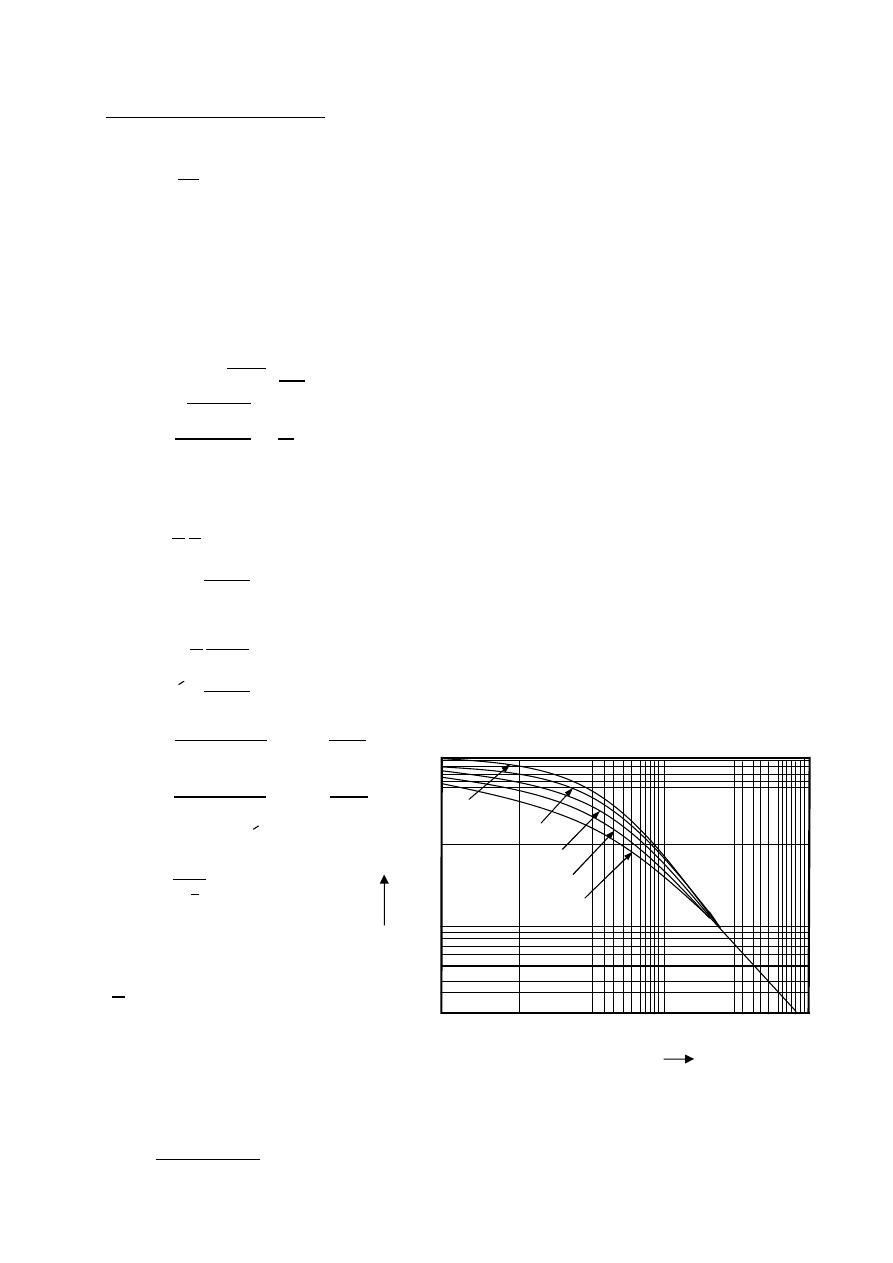
128
ﺎﺋﯿﺔــﺑﺮﮭﻜﻟا ﺔﺳﺪﻨﮭﻟا ﻢﺴﻗ ﻞــــﺻﻮﻤﻟا ﺔﻌﻣﺎﺟ
ﺎﻻتــﺼﺗﻻاو ﻚـــﯿﻧوﺮﺘﻜﻟﻻا عﺮـــــــــــــــﻓ
ﺎروديــﺒﻟا ﺪﻤﺤﻣ ﺪﯾﺆﻣ ناوﺮﻣ ﺐﻟﺎﻄﻟا داﺪﻋا
Ground wave propagation
The equation for ground wave propagation:
=
: ground wave field strength.
: field strength of wave at the surface of the earth a unit distance from
the transmitting antenna.
: is the distance from the transmitting antenna.
A: is the factor taking into account the ground losses.
A: depends on
( ,
, , ).
= 300
mv
m
in KW ,
= 1 is not given
or
=
90
v
m
in W ,
≃ 1m
1- For vertically polarization.
=
=
+
1
2- For horizontally polarization.
=
=
−
1
=
1.8×10
12
(
)
in
or
=
1.8×10
12
(
)
in
= 180 −
=
10
4
1
3
Km
: numerical distance.
: phase constant.
: distance in wave length.
: is the ground conductivity.
: is the dielectric constant
of the ground.
The attenuation factor A may be represented by the following formula
=
2+0.3
2
+ +
0.6
2
0.01
0.1
1.0
10
100
1000
0.001
0.01
0.1
1
Numerical distance a
A
b = 0°
b = 30°
b = 60°
b = 90°
b = 180°

129
ﺎﺋﯿﺔــﺑﺮﮭﻜﻟا ﺔﺳﺪﻨﮭﻟا ﻢﺴﻗ ﻞــــﺻﻮﻤﻟا ﺔﻌﻣﺎﺟ
ﺎﻻتــﺼﺗﻻاو ﻚـــﯿﻧوﺮﺘﻜﻟﻻا عﺮـــــــــــــــﻓ
ﺎروديــﺒﻟا ﺪﻤﺤﻣ ﺪﯾﺆﻣ ناوﺮﻣ ﺐﻟﺎﻄﻟا داﺪﻋا
Ex:-
A transmitter operating frequency 1.69 MHz provides strength of at least
0.5m V/m at a distance of 16 Km. transmitting antenna has 50% efficiency
and produces a radiated field that is proportional to the cosine of the angle
of elevation ( Vertical polarization ). The ground has conductivity of
5 × 10 mho/cm ,and the relative dielectric constant of 15 determine
The transmitter power required.
The solution:- F = 1.69 MHz ,
= 0.5 × 10 ,
= 15 , = 5 × 10 mho/cm
=
1.8×10
12
(
)
=
1.8×10
12
×5×10
−3
×10
−2
1.69×10
6
= 53.25
=
+
1
=
15
+
1
53.25
⟹
= 16.7
=
=
3×10
8
1.69×10
6
= 177.5 m
=
=
53.25
16000
177.5
16.7 = 5.1
=
2+0.3
2
+ +
0.6
2
=
2+0.3
(
5.1
)
2
+
5.1
+
0.6
(
5.1
)
2
= 0.15
=
⟹
0.5 × 10
= 0.15
16000
⟹
= 53.33 V/m
=
= 0.5 × 1 = 0.5
=
90
⟹
53.33 =
90 (0.5)
1
⟹
= 63.2 W
Ex:-
Find electric field strength at 10 Km distance from 1.5 MHz transmitting
having
= 2500 mV/m over ground path , = 3 m mho/cm and
= 7
assume vertical polarization.
The solution:- F = 1.5 MHz ,
= 2500 × 10 ,
= 7 , = 3 × 10 mho/cm
=
1.8×10
12
(
)
=
1.8×10
12
×3×10
−3
1.5×10
6
×100
= 36
=
+
1
=
7
+
1
36
⟹
= 12.5
=
=
3×10
8
1.5×10
6
= 200 m
=
=
35
10000
200
12.5 = 4.25
=
2+0.3
2
+ +
0.6
2
=
2+0.3
(
4.25
)
2
+
4.25
+
0.6
(
4.25
)
2
= 0.19
=
= 0.19
2500×10
−3
10000
= 47.5 V/m

130
ﺎﺋﯿﺔــﺑﺮﮭﻜﻟا ﺔﺳﺪﻨﮭﻟا ﻢﺴﻗ ﻞــــﺻﻮﻤﻟا ﺔﻌﻣﺎﺟ
ﺎﻻتــﺼﺗﻻاو ﻚـــﯿﻧوﺮﺘﻜﻟﻻا عﺮـــــــــــــــﻓ
ﺎروديــﺒﻟا ﺪﻤﺤﻣ ﺪﯾﺆﻣ ناوﺮﻣ ﺐﻟﺎﻄﻟا داﺪﻋا
Ex:-
A 50 KW transmitter employs a vertical grounded antenna with a directivity
of 2. If the transmitter frequency is 1 MHz , find the ground wave field
strength at a distance of 100 Km. assume
= 15 , = 10 mho/m
The solution:- F = 1MHz ,
= 50 KW ,
= 15 , = 10 mho/m
=
1.8×10
4
(
)
=
1.8×10
4
×10
−3
1
= 18
=
+
1
=
15
+
1
18
⟹
= 41.6
=
=
3×10
8
1×10
6
= 300 m
=
=
18
100×10
3
300
41.6 = 43.48
=
2+0.3
2
+ +
0.6
2
=
2+0.3
(
43.48
)
2
+
43.48
+
0.6
(
43.48
)
2
= 0.0127
=
= 1 × 2 = 2
=
90
=
90 ×50×10
3
×2
1
= 3000 V/m
=
= 0.0127
3000
100000
= 381 V/m
Ex:-
A 50 KW transmitter employs a vertical grounded dipole with a gain of 1.5
If the transmitter frequency is 1 MHz , find the electric field strength at
100 Km distance(neglect ground losses).
The solution:- F = 1MHz ,
= 50 KW ,
= 1.5 , = 100 × 10 mho/m
=
90
=
90 ×50×10
3
×1.5
1
= 2598 V/m
or
= 300
= 300√50 × 1.5
= 2598 V/m
neglect ground losses A=1
=
= 1
2598
100000
= 25980 V/m
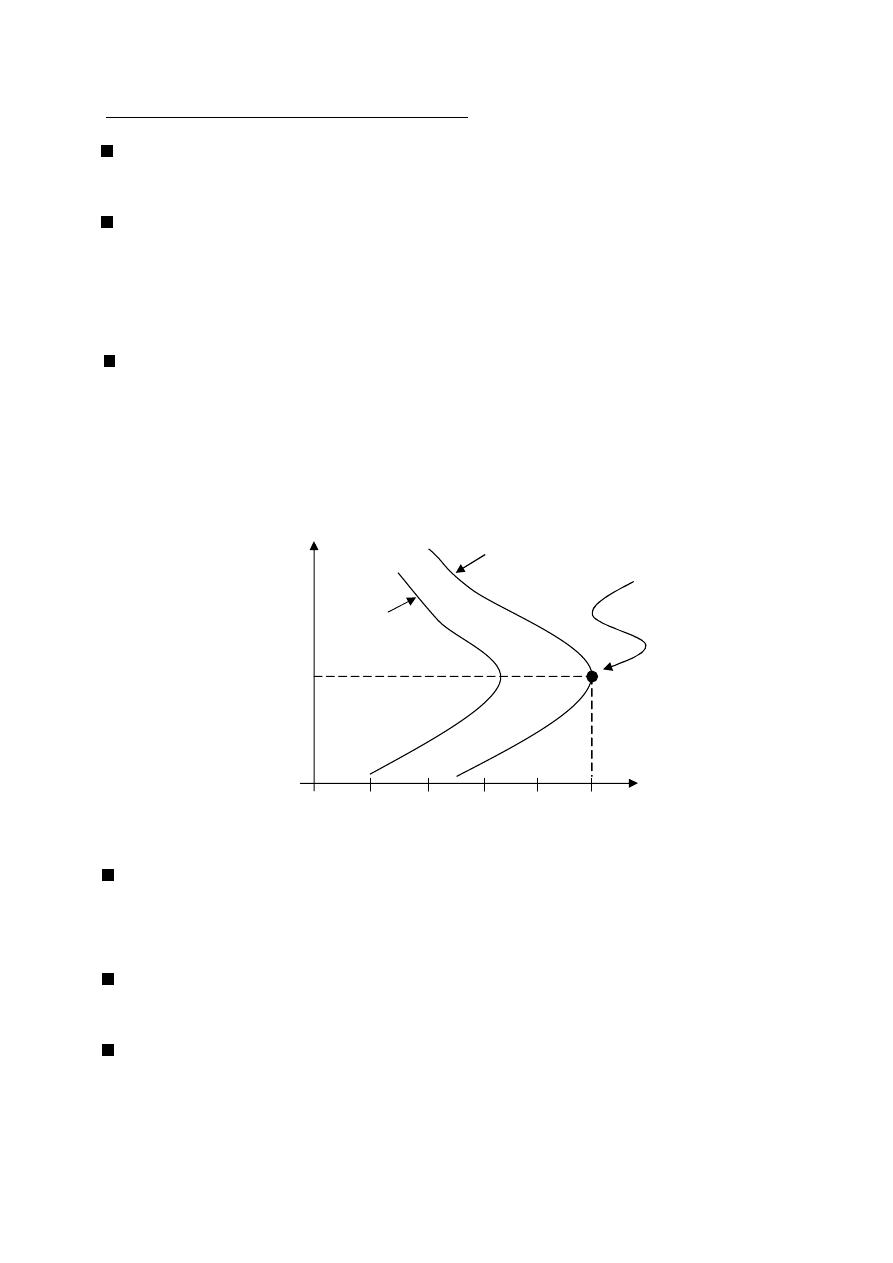
131
ﺎﺋﯿﺔــﺑﺮﮭﻜﻟا ﺔﺳﺪﻨﮭﻟا ﻢﺴﻗ ﻞــــﺻﻮﻤﻟا ﺔﻌﻣﺎﺟ
ﺎﻻتــﺼﺗﻻاو ﻚـــﯿﻧوﺮﺘﻜﻟﻻا عﺮـــــــــــــــﻓ
ﺎروديــﺒﻟا ﺪﻤﺤﻣ ﺪﯾﺆﻣ ناوﺮﻣ ﺐﻟﺎﻄﻟا داﺪﻋا
wave Propagation
(Sky)(Short)
Ion spheric
Propagation over long distance of thousand kilometer or more are almost carried
out by sky waves.
In sky wave propagation the waves are reflected from different parts of the ionized
Layers. which are always in random motion.
the received signal is the vector sum of all of those randomly varying components
(this is called fading).
The state of the ionosphere is found to vary from hour to hour , day to day,
& season to season.
Ionosphere wave propagation is less stable & depending upon frequency & upon
The condition of the ion sphere.
at great heights the ionized radiations are very intense but the atmosphere is rare
and then there are few molecules present to be ionized , therefore in this region
the ionization density (number of ions or electrons per unit volume is very low).
as the height is decreased the ionization density is increase until a height is reached
where the ionization density is maximum.
as the height is decreased more , the ionization is go to decreased minimum.
day
night
F
2
10
10
10
10
10
10
2
3
4
5
6
maximum ionization
Density = 10 / cm
6
3
(10 , 300 Km)
6
Altitude (Km)
Electron
Density/cm
3

132
ﺎﺋﯿﺔــﺑﺮﮭﻜﻟا ﺔﺳﺪﻨﮭﻟا ﻢﺴﻗ ﻞــــﺻﻮﻤﻟا ﺔﻌﻣﺎﺟ
ﺎﻻتــﺼﺗﻻاو ﻚـــﯿﻧوﺮﺘﻜﻟﻻا عﺮـــــــــــــــﻓ
ﺎروديــﺒﻟا ﺪﻤﺤﻣ ﺪﯾﺆﻣ ناوﺮﻣ ﺐﻟﺎﻄﻟا داﺪﻋا
In the ionosphere region the relative permittivity may be separated into real
& imaginary parts as follows:
=
−
= 1 −
2
m
o
(
2
+
2
)
=
o
=
2
m
(
2
+
2
)
N: electron density (number of electron per cubic meter (
/
)).
:
collision frequency.
m: electron mass =
9.1 × 10
Kg.
e : electron charge =
1.6 × 10
C.
:
depends on (gas pressure , electron thermal velocity , ion density)
Not:- maximum conductivity occurs when
ω = .
=
2
m
(
2
+
2
)
⟹
=
2
2m
2
⟹
=
2
2m
max conductivity.
Proof :
=
2
m
(
2
+
2
)
=
+
−
(2m )
(
+
)
0 =
m
2
+
2
2
−
2
(2m )
m
(
2
+
2
)
m(
+
)
−
(2m ) =
0
m
+
m
− 2m
=
0
m
− m
=
0
m
= m
=
⟹
∴
=
at great height is small (
≫ )
∴
≃ 0
⟹
=
at low height is large (
≫
)
again becomes small
∴
≃ 0
⟹
=
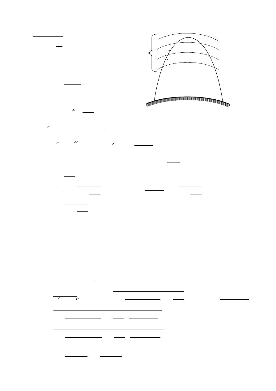
133
ﺎﺋﯿﺔــﺑﺮﮭﻜﻟا ﺔﺳﺪﻨﮭﻟا ﻢﺴﻗ ﻞــــﺻﻮﻤﻟا ﺔﻌﻣﺎﺟ
ﺎﻻتــﺼﺗﻻاو ﻚـــﯿﻧوﺮﺘﻜﻟﻻا عﺮـــــــــــــــﻓ
ﺎروديــﺒﻟا ﺪﻤﺤﻣ ﺪﯾﺆﻣ ناوﺮﻣ ﺐﻟﺎﻄﻟا داﺪﻋا
Snell's Law
=
1
2
=
=
Let
= 1 for both regions
=
(
)
at high frequencies
⟹
≫
= 0
⟹
=
o
= 0
∴
= 1 −
2
m
o
(
2
+
2
)
= 1 −
2
m
o
2
=
−
⟹
=
= 1 −
2
m
o
2
m =
9.1 × 10
Kg , e =
1.6 × 10
C ,
=
10
−9
36
= 1 −
81
2
(
: /
, F: Hz )
=
√
=
1 −
81
2
⟹
=
(
)
=
1 −
81
2
=
1 −
81
2
If
> 81
⟹
the refractive index is always less than unity.
If
< 81
⟹
the refractive index is imaginary which under such condition
the radio waves are attenuated at this frequency and ion sphere region is not
able to transmit or bend.
Ex
:- Derive an expression for the refractive index of an ionosphere layer.
Assume
ω =
The solution:-
=
√
=
√
−
⟹
=
1 −
2
m
o
(
2
+
2
)
−
o
where
=
2
m
(
2
+
2
)
=
1 −
2
m
o
(
2
+
2
)
−
1
o
2
m
(
2
+
2
)
Assume
ω =
=
1 −
2
m
o
(
2
+
2
)
−
1
o
2
m
(
2
+
2
)
=
1 −
2
2m
2
o
−
2
2m
2
o
t
θ
i
θ
ion sphere
free space
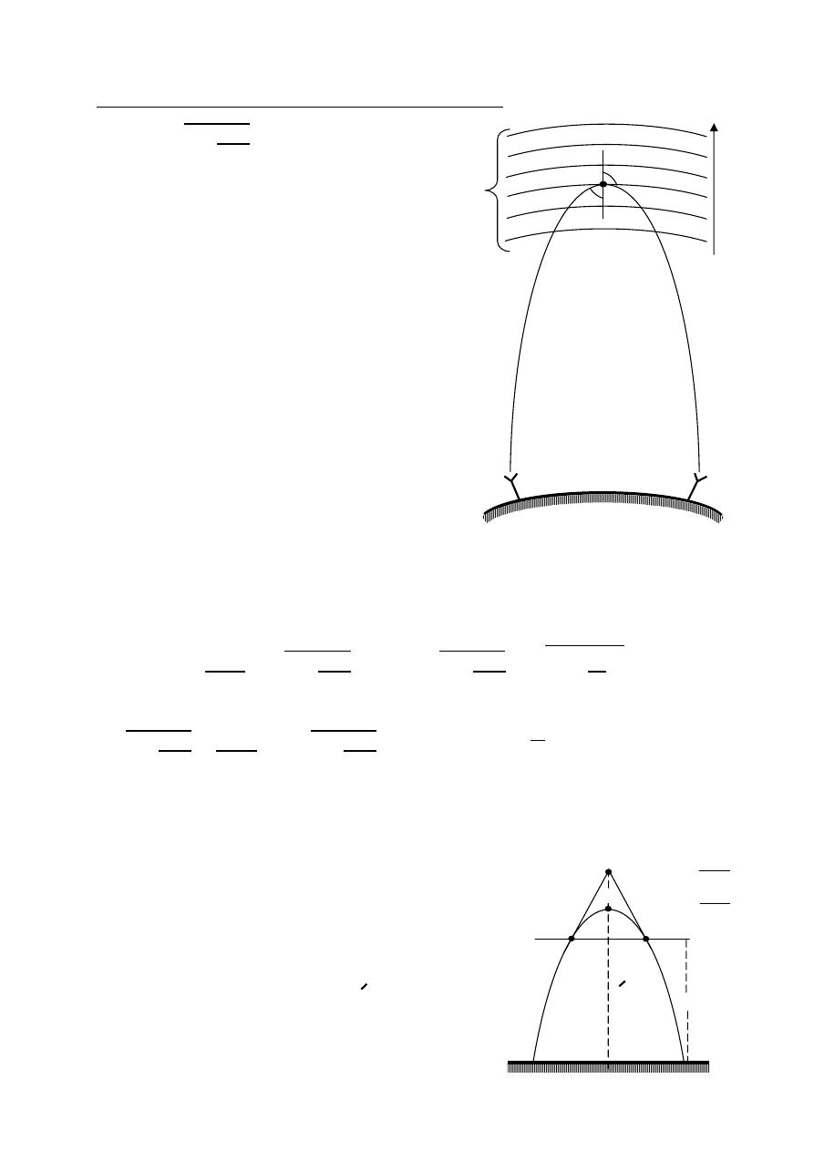
134
ﺎﺋﯿﺔــﺑﺮﮭﻜﻟا ﺔﺳﺪﻨﮭﻟا ﻢﺴﻗ ﻞــــﺻﻮﻤﻟا ﺔﻌﻣﺎﺟ
ﺎﻻتــﺼﺗﻻاو ﻚـــﯿﻧوﺮﺘﻜﻟﻻا عﺮـــــــــــــــﻓ
ﺎروديــﺒﻟا ﺪﻤﺤﻣ ﺪﯾﺆﻣ ناوﺮﻣ ﺐﻟﺎﻄﻟا داﺪﻋا
Mechanism of radio wave bending by the ionosphere
=
1 −
81
2
Since n < 1
⟹
<
i.e angle of refraction will go on deviating
from the normal as the wave raver medium
if successive layers of ion sphere are of higher
electron density
>
>
>
>
>
if means n will go in decreasing and decreasing
i.e
>
>
>
>
>
.
thus the wave will enters at say point P will be
deviating more and more at point will reach
where it travels parallel to erath at Pm.
at Pm the angle of refraction is 90° and Pm
is highest point in the ionosphere reached by
the radio wave .
=
90 = 1 and
=
Pm is also called as point of refraction.
Critical frequency :- the critical frequency of an ionized layer of the ion sphere
is define as the highest frequency which can be reflected by
a particular layer at vertical incidence.
=
=
1 −
81
2
,
=
1 −
81
2
=
1 −
2
at vertical incidence
⟹
= 0
1 −
81
2
=
0
⟹
1 −
81
2
= 0
⟹
= 9√
Virtual height :- virtual height of an ion sphere layer may be defined as a height
to which a short pulse of energy sent vertically up word and
traveling with the speed of light world reach
taking the same two ways travel time
as does the actual pulse reflected from
the layer. The virtual height is
always greater than the actual height.
or the virtual height h is that height
from which a wave sent up at an
angle appears to be reflected.
in free
space
N
6
N
5
N
4
N
3
N
2
N
1
n
decre-
asing
Pm
t
θ
i
θ
T
R
F
c
: in MHz
N: electron/m
3
A
B
C
D
h
h
t
1
=
t
2
=
d
1
v
1
v
2
d
2
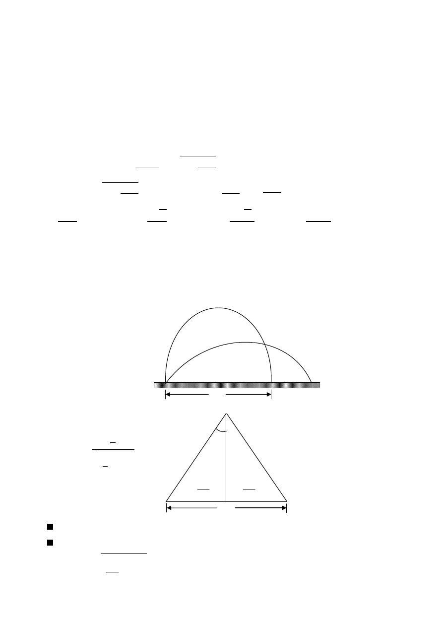
135
ﺎﺋﯿﺔــﺑﺮﮭﻜﻟا ﺔﺳﺪﻨﮭﻟا ﻢﺴﻗ ﻞــــﺻﻮﻤﻟا ﺔﻌﻣﺎﺟ
ﺎﻻتــﺼﺗﻻاو ﻚـــﯿﻧوﺮﺘﻜﻟﻻا عﺮـــــــــــــــﻓ
ﺎروديــﺒﻟا ﺪﻤﺤﻣ ﺪﯾﺆﻣ ناوﺮﻣ ﺐﻟﺎﻄﻟا داﺪﻋا
maximum usable frequency(MUF):- the maximum possible value of frequency
for which reflection take place for a given
distance of propagation is called as
the maximum usable frequency for
the distance.
=
Ex:-
Prove that
=
.
The solution:-
=
=
1 −
81
2
where
= 90
=
1 −
81
2
⟹
= 1 −
81
2
⟹
= 1 −
2
=
2
⟹
√
=
⟹
√
=
⟹
=
=
.
Skip distance(D):- the skip distance represent the minimum distance from
the transmitter at which a sky wave of a given frequency
will be returned to earth by the ion sphere.
=
2
2
2
+ℎ
2
Since the MUF Fm is for which the waves is returned
For wave return to earth , angle of refraction
= 90
⟹
=
= 2ℎ
− 1
D
ion sphere
h
o
θ
i
D
2
2
D
D

136
ﺎﺋﯿﺔــﺑﺮﮭﻜﻟا ﺔﺳﺪﻨﮭﻟا ﻢﺴﻗ ﻞــــﺻﻮﻤﻟا ﺔﻌﻣﺎﺟ
ﺎﻻتــﺼﺗﻻاو ﻚـــﯿﻧوﺮﺘﻜﻟﻻا عﺮـــــــــــــــﻓ
ﺎروديــﺒﻟا ﺪﻤﺤﻣ ﺪﯾﺆﻣ ناوﺮﻣ ﺐﻟﺎﻄﻟا داﺪﻋا
Ex:-
Explain the terms MUF and skip distance. Show that on flat earth the skip
distance for a given frequency is given by:
= 2ℎ
− 1
The solution:-
=
2
2
2
+ℎ
2
⟹
2
+ ℎ =
2
2
4
+ ℎ
=
2
4
⟹
4
+ ℎ
2
=
4
2
⟹
ℎ
2
=
4
2
−
4
ℎ =
2
4
1
2
−
1
⟹
ℎ =
2
4
1−
2
2
⟹
= 4ℎ
2
2
1−
2
= 4ℎ
2
1−
2
1− 1−
2
⟹
= 4ℎ
2
1−
2
2
= 4ℎ
2
1
2
−
1
where
=
⟹
=
⟹
=
= 4ℎ
2
1
−
1
⟹
= 4ℎ
2
2
2
−
1
⟹
= 2ℎ
o
2
− 1
Ex:-
Assume that reflection takes place at height of 400 Km, and that the maximum
density in the ionosphere corresponding to 0.9 reflection index 10 MHz.
what will be the range (assume flat earth) for which the MUF is 10 MHz.
the solution:-
=
1 −
2
0.9 =
1 −
10×10
6
2
= 4.36 MHz
= 2ℎ
− 1
= 2 × 400 × 10
10×10
6
4.36×10
6
− 1
= 1651.27 Km
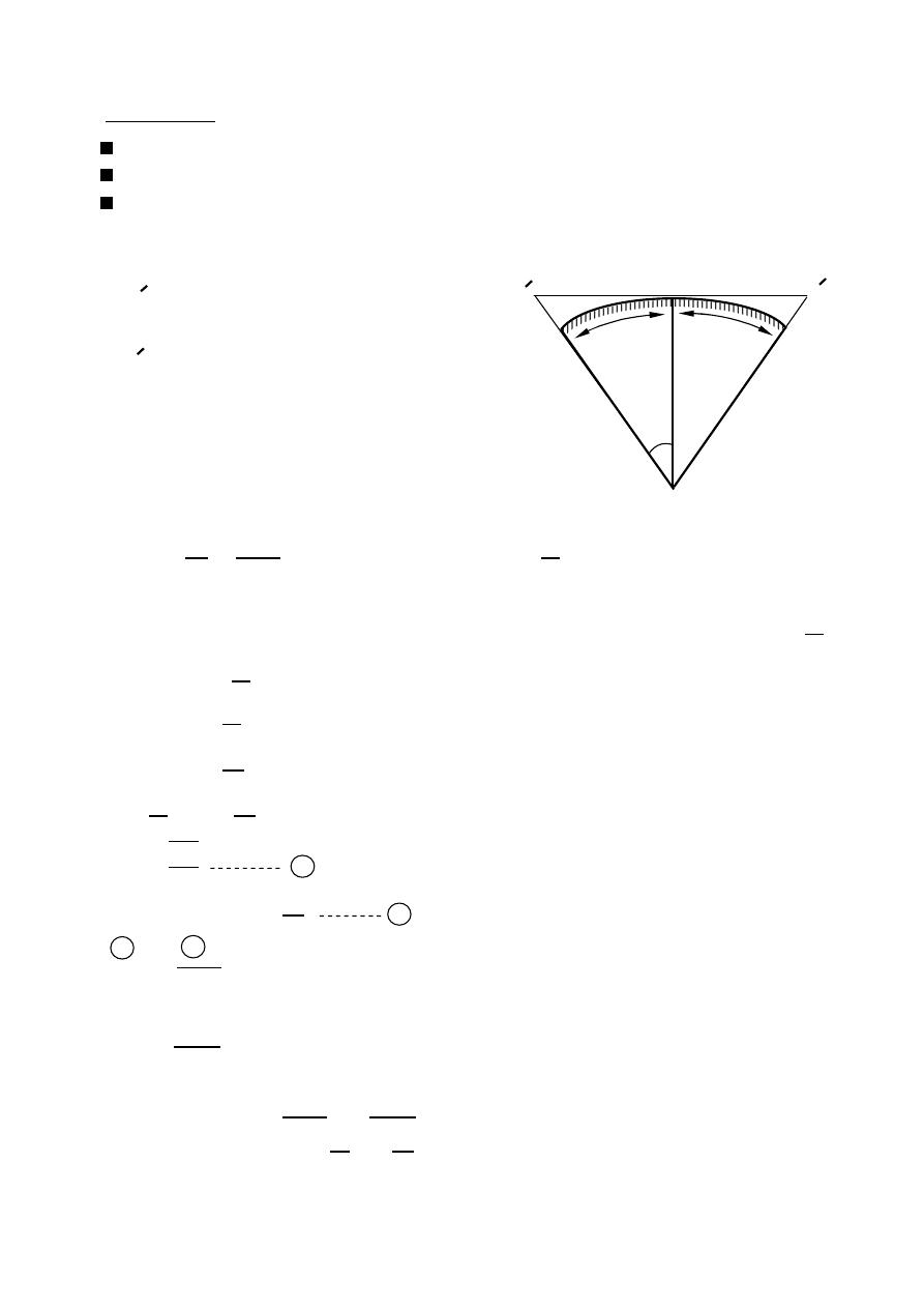
137
ﺎﺋﯿﺔــﺑﺮﮭﻜﻟا ﺔﺳﺪﻨﮭﻟا ﻢﺴﻗ ﻞــــﺻﻮﻤﻟا ﺔﻌﻣﺎﺟ
ﺎﻻتــﺼﺗﻻاو ﻚـــﯿﻧوﺮﺘﻜﻟﻻا عﺮـــــــــــــــﻓ
ﺎروديــﺒﻟا ﺪﻤﺤﻣ ﺪﯾﺆﻣ ناوﺮﻣ ﺐﻟﺎﻄﻟا داﺪﻋا
(Space wave propagation)
Troposphere
Useful for VHF and higher frequencies.
Propagation in these frequencies are limited to a few tens of kilometers.
Since space wave propagation in through troposphere
It is called troposphere propagation.
1- Range
TT(
ℎ ) height of the transmitting antenna
above the earth.
RR(
ℎ ) height of the receiving antenna
above the earth.
d: distance between transmitting & receiving
antenna.
=
+
a: radius of the earth.
=
=
+ℎ
= ( + ℎ )
=
( +
ℎ
)
Note: (
1 + )
= 1 −
+
−
….
Since the
ℎ ≪
⟹
expand by binomial theorem and neglect high power of
ℎ
= (1 −
ℎ
+neglect)
= 1 −
ℎ
= 1 −
2
2
( For small
)
1 −
ℎ
= 1 −
2
2
=
2ℎ
1
=
⟹
=
1
2
2 in 1
=
2 ℎ
In the same manner
=
2 ℎ
∴ the range =
+
=
2 ℎ + 2 ℎ where = 6.37 × 10 m
∴
= 3.57
ℎ + ℎ Km
C
T
R
R
T
a
a
a
o
d
d
1
2
α
h
h
t
r
Ex:- Derive an expression for
the range of line of sight
space wave propagation.
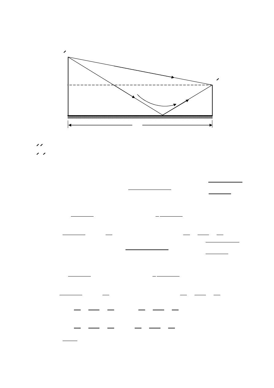
138
ﺎﺋﯿﺔــﺑﺮﮭﻜﻟا ﺔﺳﺪﻨﮭﻟا ﻢﺴﻗ ﻞــــﺻﻮﻤﻟا ﺔﻌﻣﺎﺟ
ﺎﻻتــﺼﺗﻻاو ﻚـــﯿﻧوﺮﺘﻜﻟﻻا عﺮـــــــــــــــﻓ
ﺎروديــﺒﻟا ﺪﻤﺤﻣ ﺪﯾﺆﻣ ناوﺮﻣ ﺐﻟﺎﻄﻟا داﺪﻋا
2- Field Strength
Neglecting the earth's curvature
⃗
= ⃗ + ⃗
TR : is the direct path.
ToR: is the ground reflected wave.
Let
is the field strength due to the direct wave.
assume the reflection at the earth is perfect.
= (ℎ − ℎ ) +
⟹
=
(ℎ − ℎ ) +
⟹
=
ℎ −ℎ
2
2
+ 1
=
1 +
ℎ −ℎ
2
2
0.5
⟹
=
1 +
1
2
ℎ −ℎ
2
2
+ ⋯
=
+
ℎ −ℎ
2
2
=
+
1
2
(ℎ − 2ℎ ℎ + ℎ ) =
+
ℎ
2
2
−
ℎ ℎ
+
ℎ
2
2
= (ℎ + ℎ ) +
⟹
=
(ℎ + ℎ ) +
⟹
=
ℎ +ℎ
2
2
+ 1
=
1 +
ℎ +ℎ
2
2
0.5
⟹
=
1 +
1
2
ℎ +ℎ
2
2
+ ⋯
=
+
ℎ +ℎ
2
2
=
+
1
2
(ℎ + 2ℎ ℎ + ℎ ) =
+
ℎ
2
2
+
ℎ ℎ
+
ℎ
2
2
−
=
+
ℎ
2
2
+
ℎ ℎ
+
ℎ
2
2
−
+
ℎ
2
2
−
ℎ ℎ
+
ℎ
2
2
−
=
+
ℎ
2
2
+
ℎ ℎ
+
ℎ
2
2
−
−
ℎ
2
2
+
ℎ ℎ
−
ℎ
2
2
−
=
2ℎ ℎ
−
: path difference
neglect
neglect
d
d
1
2
d
o
R
R
T
T
t
r
h
h

139
ﺎﺋﯿﺔــﺑﺮﮭﻜﻟا ﺔﺳﺪﻨﮭﻟا ﻢﺴﻗ ﻞــــﺻﻮﻤﻟا ﺔﻌﻣﺎﺟ
ﺎﻻتــﺼﺗﻻاو ﻚـــﯿﻧوﺮﺘﻜﻟﻻا عﺮـــــــــــــــﻓ
ﺎروديــﺒﻟا ﺪﻤﺤﻣ ﺪﯾﺆﻣ ناوﺮﻣ ﺐﻟﺎﻄﻟا داﺪﻋا
The phase difference (
−
) =
2 2ℎ ℎ
=
4 ℎ ℎ
phase difference
The resultant field strength at R is given by
=
+
K: reflection coefficient
=
+
: phase difference due to the path difference
4 ℎ ℎ
.
:
phase difference due to the path reflection from ground
|
|
=
(
1 +
)
2
+
2
2
For perfect reflection
= 1∠180
=
√
1 + 2
+
2
+
2
=
√
1 + 2
+ 1
=
√
2 + 2
=
1
2
(1 +
2 )
=
2
(
1 +
)
2
=
1
2
(1 +
)
=
2 2
2
2
=
4
2
2
= 2
2
Ex:-
A transmitting antenna is elevated 30m above the grounds a receiving antenna
5 Km distance is elevated 10m , determine the space wave field strength at
The receiving antenna when transmitting antenna operates 50 MHz.
= 0.94∠−180 ,
= 1V/m
The solution:-
=
+ ,
=
=
3×10
8
50×10
6
= 6m
=
4 ℎ ℎ
=
4 ×30×10
6×5000
= 7.2
o
,
= −180
o
= 7.2
o
−
180
o
= −172.8
o
|
|
=
(
1 +
)
2
+
2
2
|
|
= 1
1 + 0.94
(
−172.8
)
2
+ (0.94)
2
2
(
−172.8
)
= 135.7 mV/m
Due to the
direct path
Due to the
reflected path
Ex:- Derive an expression for
the space wave field strength
(assume perfect reflection)

140
ﺎﺋﯿﺔــﺑﺮﮭﻜﻟا ﺔﺳﺪﻨﮭﻟا ﻢﺴﻗ ﻞــــﺻﻮﻤﻟا ﺔﻌﻣﺎﺟ
ﺎﻻتــﺼﺗﻻاو ﻚـــﯿﻧوﺮﺘﻜﻟﻻا عﺮـــــــــــــــﻓ
ﺎروديــﺒﻟا ﺪﻤﺤﻣ ﺪﯾﺆﻣ ناوﺮﻣ ﺐﻟﺎﻄﻟا داﺪﻋا
Ex:-
At what frequency a wave must propagate for D-region to have an index
of refraction 0.5 given N = 400 electron/
cm
the solution:-
=
1 −
81
2
,
=
400
(10
−2
)
3
= 400 × 10
6
electron/
m
= 1 −
81
2
⟹
81
2
= 1 −
⟹
=
81
1
2
=
81
1
2
=
81×400
×
10
6
1 (0.5)
2
= 207.85 KHz
Ex:-
An electromagnetic wave is propagated through the D-region with an index
of the refraction of 0.5 and an electron density of
3.24 × 10 electron/cm
if the incident angle is 30°, determine critical frequency , maximum usable
frequency , and wave frequency.
The solution:-
=
3.24×10
4
(10
−2
)
3
= 3.24 × 10
10
electron/
m
= 9√
= 9√3.24 × 10
= 1.62 MHz
=
⟹
=
=
1.62×10
6
30
= 1.87 MHz
=
1 −
81
2
⟹
= 1 −
81
2
⟹
81
2
= 1 −
=
81
1
2
⟹
=
81
1
2
=
81×3.24
×
10
10
1 (0.5)
2
= 1.87 MHz
Ex:-
A VHF communication is to be established at 90 MHz. find the distance
up to which line of sight communication may be possible if the height of
the transmitting and receiving antennas are 40m and 25m respectively. also
determine the field strength at the receiving end (assume perfect reflection
and
= 1 V/m).
the solution:-
= 3.57
ℎ + ℎ Km
= 3.57 √40 + √25 = 40.43 Km
perfect reflection
= 1∠180 , =
=
3×10
8
90×10
6
=
10
3
m
=
4 ℎ ℎ
=
4 ×40×25
10
3
×40430
= 5.3
o
=
+
= 5.3
o
+
180
o
= 185.3
o
|
|
=
(
1 +
)
2
+
2
2
|
|
= 1
1 +
(
185.3
)
2
+ (1)
2
2
(
185.3
)
= 92.5 mV/m

141
ﺎﺋﯿﺔــﺑﺮﮭﻜﻟا ﺔﺳﺪﻨﮭﻟا ﻢﺴﻗ ﻞــــﺻﻮﻤﻟا ﺔﻌﻣﺎﺟ
ﺎﻻتــﺼﺗﻻاو ﻚـــﯿﻧوﺮﺘﻜﻟﻻا عﺮـــــــــــــــﻓ
ﺎروديــﺒﻟا ﺪﻤﺤﻣ ﺪﯾﺆﻣ ناوﺮﻣ ﺐﻟﺎﻄﻟا داﺪﻋا
Ex:-
A 15 MHz wave is propagated through the ion sphere region with an electron
density of
1.24 × 10 electron/m . determine the attenuation factor for this
wave. If 1-
≫ . 2-
= .
The solution:-
1-
≫
=
2
m
(
2
+
2
)
≃ 0
=
2
1 +
2
− 1 =
2
1 + (0)
2
− 1 = 0
2-
=
=
2
m
(
2
+
2
)
⟹
=
2
m
(
2
+
2
)
⟹
=
2
2m
2
⟹
=
2
2m
=
1.24×10
12
(1.6×10
−19
)
2
2×9.1×10
−31
×2 ×15×10
6
= 1.85 × 10
−4
= 1 −
2
m
o
(
2
+
2
)
⟹
= 1 −
2
2m
o
2
S/m
= 1 −
1.24×10
12
(1.6×10
−19
)
2
2×9.1×10
−31
×
10−9
36
× 2 ×15×10
6 2
= 0.778
=
o
=
1.85×10
−4
2 ×15×10
6
×
10−9
36
= 0.222
=
−
= 0.778
−
0.222
=
=
10
−9
36
(
0.778
−
0.222
)
=
2
1 +
2
− 1 = 0.0381 − 0.005 neper/m
Ex:-
A high frequency radio link has to be established between two points at
a distance of 2500 Km on earth's surface. Considering the ionospheric
height to be 200 Km and its critical frequency 5 MHz, calculate MUF for
the given path .
The solution:-
= 2ℎ
− 1
=
2
− 1
⟹
ℎ
=
− 1
⟹
ℎ
+ 1 =
=
2ℎ
+ 1 = 5 × 10
2500
×
10
3
2
×
200
×
10
3
+ 1 = 31.65 MHz
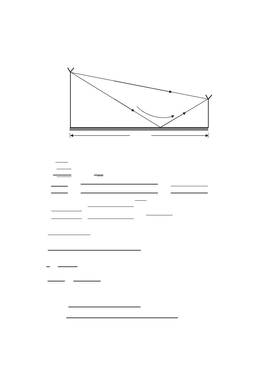
142
ﺎﺋﯿﺔــﺑﺮﮭﻜﻟا ﺔﺳﺪﻨﮭﻟا ﻢﺴﻗ ﻞــــﺻﻮﻤﻟا ﺔﻌﻣﺎﺟ
ﺎﻻتــﺼﺗﻻاو ﻚـــﯿﻧوﺮﺘﻜﻟﻻا عﺮـــــــــــــــﻓ
ﺎروديــﺒﻟا ﺪﻤﺤﻣ ﺪﯾﺆﻣ ناوﺮﻣ ﺐﻟﺎﻄﻟا داﺪﻋا
Ex:-
A dipole radiator is elevated 30m above the ground . A receiving dipole
5 Km
distant is elevated 10m . determine the space wave field strength
(for parallel polarization) at the receiving antenna at a frequency of 50 MHz
(assume
= 1 V/m).
= 15 ,
= 5 × 10 mho/m .
The solution:-
=
,
=
=
5000
40
⟹
= 89.54
=
1
1
2
2
=
1
15
(89.54)
⟹
= 14.96
=
+
=
2 ×50×10
6
×4 ×10
−7
0.005+ 2 ×50×10
6
×
10−9
36
×15
=
395
0.005+ 0.0416
=
395
∠
90
o
0.0419
∠
83
o
395
∠
90
o
−∠
83
o
0.0419
= √9427
∠
7 = 97
∠
3.5 Ω
=
2
−
1
2
+
1
=
97
∠
3.5
o
cos 89.54 −120 cos (14.96)
97
∠
3.5
o
cos 89.54 +120 cos (14.96)
= 1∠180
=
=
3×10
8
50×10
6
= 6 m
=
4 ℎ ℎ
=
4 ×30×10
6×5000
= 7.2
o
=
+
= 7.2
o
+
180
o
= 187.2
o
|
|
=
(
1 +
⊥
)
2
+
⊥
2
2
|
|
= 1
1 + 1 ×
(
187.2
)
2
+ (1)
2
2
(
187.2
)
|
|
= 125.6 mV/m
1
d
d
2
30m
10m
5000m
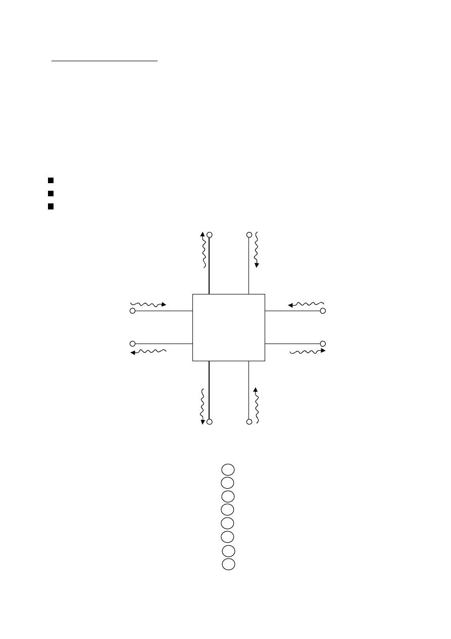
143
ﺎﺋﯿﺔــﺑﺮﮭﻜﻟا ﺔﺳﺪﻨﮭﻟا ﻢﺴﻗ ﻞــــﺻﻮﻤﻟا ﺔﻌﻣﺎﺟ
ﺎﻻتــﺼﺗﻻاو ﻚـــﯿﻧوﺮﺘﻜﻟﻻا عﺮـــــــــــــــﻓ
ﺎروديــﺒﻟا ﺪﻤﺤﻣ ﺪﯾﺆﻣ ناوﺮﻣ ﺐﻟﺎﻄﻟا داﺪﻋا
Parameters)
-
(S
Parameters
Scattering
Notes:- voltage & current are not well defined for a microwave (why)?
because: 1- Equipment is not readily available to measure total voltage and total
current at the ports of the network.
2- Short & open circuits are difficult to achieve over broad band of
frequencies.
3- Active devices , such as power transistors & tunnel diodes frequently
will not have stability for short or open circuit.
It is possible to define voltage as being proportional to the transverse electric field.
It is possible to define current as being proportional to the transverse magnetic field.
The product gives the power flow through the network.
S-Parameters
: represent the incident wave at port 1
: represent the reflected wave at port 1
: represent the incident wave at port 2
: represent the reflected wave at port 2
: represent the incident wave at port 3
: represent the reflected wave at port 3
: represent the incident wave at port n
: represent the reflected wave at port n
a
a
a
a
b
b
b
b
n
n
2
2
1
1
3
3
Z
Z
Z
Z
3
2
1
n
01
0n
03
02
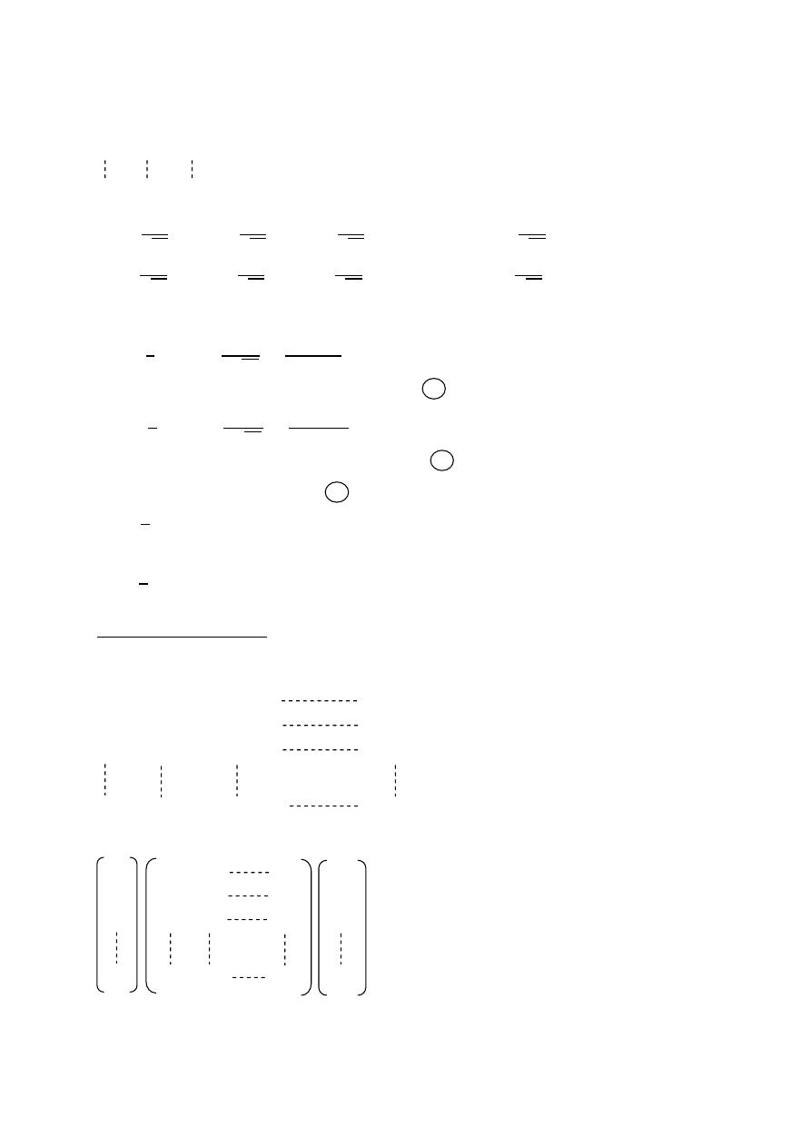
144
ﺎﺋﯿﺔــﺑﺮﮭﻜﻟا ﺔﺳﺪﻨﮭﻟا ﻢﺴﻗ ﻞــــﺻﻮﻤﻟا ﺔﻌﻣﺎﺟ
ﺎﻻتــﺼﺗﻻاو ﻚـــﯿﻧوﺮﺘﻜﻟﻻا عﺮـــــــــــــــﻓ
ﺎروديــﺒﻟا ﺪﻤﺤﻣ ﺪﯾﺆﻣ ناوﺮﻣ ﺐﻟﺎﻄﻟا داﺪﻋا
=
+
=
+
=
+
=
+
=
1
,
=
2
,
=
3
………. ,
=
=
1
,
=
2
,
=
3
………. ,
=
The square of any wave variable gives the average power.
=
1
2
| | =
1
2
2
=
1
1
2
: the power in the incident wave at port 1
=
1
2
| | =
1
2
2
=
1
1
2
: the power in the reflected wave at port 1
The net power flow into port 1 is given by
=
1
2
(| | − | | )
and in general the net power flow any port given by
=
1
2
(| | − | | )
The scattering Matrix
The scattering parameters can be written
= S
+ S
+ +S
= S
+ S
+ +S
= S
+ S
+ +S
= S
+ S
+ +S
S S
S
S S S
S S S
S S S
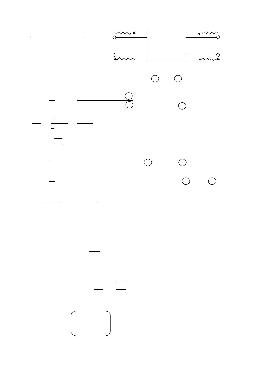
145
ﺎﺋﯿﺔــﺑﺮﮭﻜﻟا ﺔﺳﺪﻨﮭﻟا ﻢﺴﻗ ﻞــــﺻﻮﻤﻟا ﺔﻌﻣﺎﺟ
ﺎﻻتــﺼﺗﻻاو ﻚـــﯿﻧوﺮﺘﻜﻟﻻا عﺮـــــــــــــــﻓ
ﺎروديــﺒﻟا ﺪﻤﺤﻣ ﺪﯾﺆﻣ ناوﺮﻣ ﺐﻟﺎﻄﻟا داﺪﻋا
Two port network
= S
+ S
= S
+ S
S
=
1
1
S : represents the reflection coefficient at port 1 when 2 is terminated with
A matched load
S
=
2
1
=
=
|
|
|
|
=
|
|
⟹
= |S |
S
=
2
1
This factor represents the attenuation or (insertion loss)
S
=
2
2
reflection coefficient at port 2 when port 1 is matched
S
=
2
2
the attenuation for wave traveling from port 2 to port 1
S =
1+
1−
⟹
| | =
1−S
1+S
Ex:-
find the S-parameters for a two port waveguide component if the measured
VSWR = 1.3 it is also found that the power is 60 mW for an input power of
100 mW. the same results are obtained when the component is reversed
The solution:- | |
=
S−1
S+1
=
1.3−1
1.3+1
= 0.13
S
= S
=
S
=
2
1
=
60
100
= 0.774
S
= S
= 0.774
0.13 0.774
0.774 0.13
wave leaving port 2
wave intering port 1
match load port 2
S
S
S
S
11
12
21
22
a
a
b
b
1
2
2
1
146
ﺎﺋﯿﺔــﺑﺮﮭﻜﻟا ﺔﺳﺪﻨﮭﻟا ﻢﺴﻗ ﻞــــﺻﻮﻤﻟا ﺔﻌﻣﺎﺟ
ﺎﻻتــﺼﺗﻻاو ﻚـــﯿﻧوﺮﺘﻜﻟﻻا عﺮـــــــــــــــﻓ
ﺎروديــﺒﻟا ﺪﻤﺤﻣ ﺪﯾﺆﻣ ناوﺮﻣ ﺐﻟﺎﻄﻟا داﺪﻋا
Ex:-
the scatting matrix for a two port is the incident power to
Port 1 is
= 50 mW,
= 0 mW
1- calculate
,
.
2- calculate
,
.
3- find the reflected power at each port .
The solution:-
S
= S
= 0.1
S
= S
= 0.7
1-
=
1
2
| |
⟹
=
2
= √2 × 0.05 = 0.316W
=
1
2
|
|
⟹
=
2
= √2 × 0 = 0W
2-
= S
+ S
= 0.1 × 0.316 + 0.7 × 0 = 0.0316
= S
+ S
= 0.7 × 0.316 + 0.1 × 0 = 0.2212
3-
=
1
2
| | =
1
2
|0.0316| = 0.499 mW
=
1
2
| | =
1
2
|0.2212| = 0.0244 mW
parameters
-
Properties of the S
1- For an ideal n-port with no reflection at any-port
S = 0 = 1 , 2 , 3 , ….
S
= diagonal coefficients of the scattering matrix are zero
All the ports have matched load.
2- Reciprocal two port (symmetry of S-parameters)
A reciprocal two port has the same transmission characteristic in either direction.
E.x:- for two port 1 & 2
S
= S
for n-port
S = S ≠
3- Zero Property
The sum of the products of each term of any row or column multiplied by
the complex conjugate of the corresponding terms of any other row or column
is zero.
∑
S S
∗
= 0
for
≠
0.1
0.7
0.7
0.1
0
0
0
0
k = 1 , 2 , 3 , …..n
j = 1 , 2 , 3 , …..n
n
1
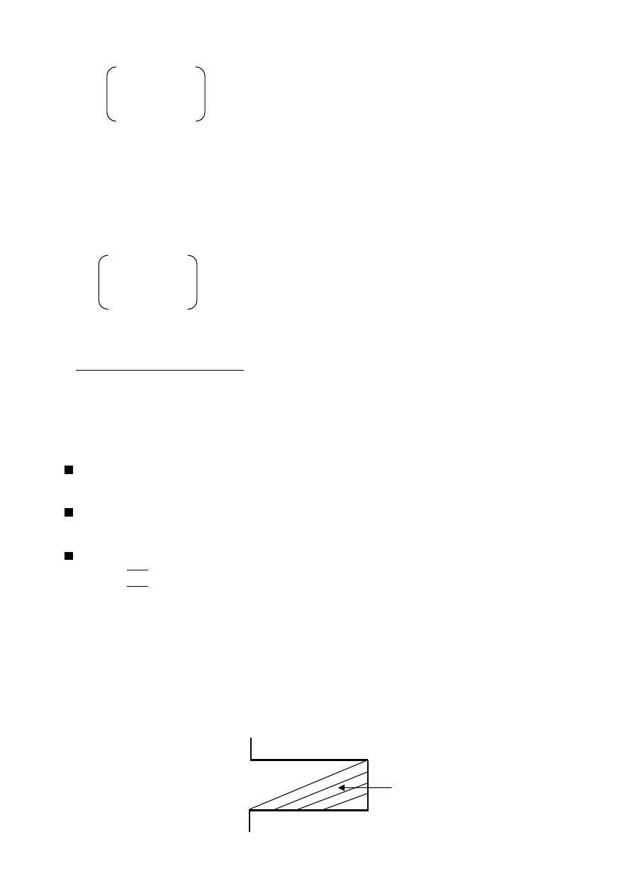
147
ﺎﺋﯿﺔــﺑﺮﮭﻜﻟا ﺔﺳﺪﻨﮭﻟا ﻢﺴﻗ ﻞــــﺻﻮﻤﻟا ﺔﻌﻣﺎﺟ
ﺎﻻتــﺼﺗﻻاو ﻚـــﯿﻧوﺮﺘﻜﻟﻻا عﺮـــــــــــــــﻓ
ﺎروديــﺒﻟا ﺪﻤﺤﻣ ﺪﯾﺆﻣ ناوﺮﻣ ﺐﻟﺎﻄﻟا داﺪﻋا
E.x
S
S
S
S
S
S
S
S
S
S S
∗
+ S S
∗
+ S S
∗
= 0
4- Unity Property
The sum of the products of each term of any one row or of any one column of
matrix S multiplied by its complex conjugate is unity.
∑
S S
∗
= 1
for
= 1 , 2 , 3 ,…. , n
S
S
S
S
S
S
S
S
S
S S
∗
+ S S
∗
+ S S
∗
= 1
Microwave Components
Microwave network consist of various microwave components and devices
connected together.
Waveguide sections:
Straight , twisted , curved , flexible sections toper (used as a transition between
Different size guides)
Materials used (brass , bronze , and for higher frequency band , silver is used to
minimize the ohmic loss )
Ideal waveguide sections should have no losses or reflections.
S
=
2
1
= 1
S
= S
= 1
S
= S
= 0
Terminations:
have an input port only.
Dissipative terminations are designed to absorb the input power.
1
n
Lossy material
(tapered)
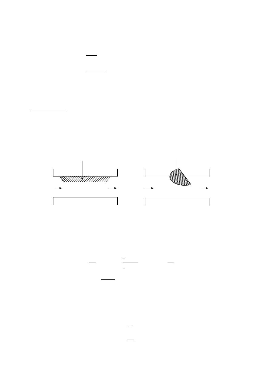
148
ﺎﺋﯿﺔــﺑﺮﮭﻜﻟا ﺔﺳﺪﻨﮭﻟا ﻢﺴﻗ ﻞــــﺻﻮﻤﻟا ﺔﻌﻣﺎﺟ
ﺎﻻتــﺼﺗﻻاو ﻚـــﯿﻧوﺮﺘﻜﻟﻻا عﺮـــــــــــــــﻓ
ﺎروديــﺒﻟا ﺪﻤﺤﻣ ﺪﯾﺆﻣ ناوﺮﻣ ﺐﻟﺎﻄﻟا داﺪﻋا
Ex:-
A waveguide terminations is used to dissipate 15 watts of power. if the
termination is specified as having VSWR (S = 1.02) find the reflected power.
The solution:-
=
S−1
S+1
=
1.02−1
1.02+1
= 0.0099
= | |
= |0.0099| × 15
= 1.5 mW
Attenuation
Attenuators are used to control power levels in a microwave system by absorbing
some of the power of an electromagnetic wave passing through.
Attenuator types :
1- fixed
2- variable
Fixed variable
=
−
: the output power.
: the input power.
: the total absorbed power in the resistive load.
Attenuation
= 10
1
2
= 10
1
2
1
2
1
2
2
2
= 10
1
1
2
Attenuation(dB)
= 10
1
S
21
2
= 10
|S |
= −20
|S |
For reciprocal attenuators
S
= S
Ex:-
the input power to a 20 dB attenuator is 100 mW . find the output power and
The power absorbed by the attenuator
The solution:- Attenuation
= 10
1
2
20 = 10
1
2
⟹
= 1 mW
=
−
= 100m − 1m = 99mW
P
1
P
2
P
1
P
2
Resistive vane
Resistive vane
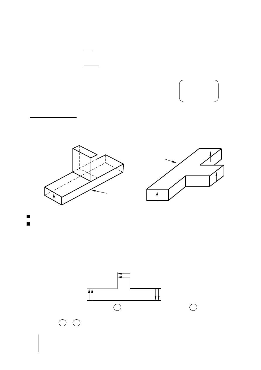
149
ﺎﺋﯿﺔــﺑﺮﮭﻜﻟا ﺔﺳﺪﻨﮭﻟا ﻢﺴﻗ ﻞــــﺻﻮﻤﻟا ﺔﻌﻣﺎﺟ
ﺎﻻتــﺼﺗﻻاو ﻚـــﯿﻧوﺮﺘﻜﻟﻻا عﺮـــــــــــــــﻓ
ﺎروديــﺒﻟا ﺪﻤﺤﻣ ﺪﯾﺆﻣ ناوﺮﻣ ﺐﻟﺎﻄﻟا داﺪﻋا
Ex:-
A 5dB waveguide attenuator is specified as having a VSWR of 1.2 assuming
That it is reciprocal . find the S-parameters of the attenuator.
The solution:-
=
S−1
S+1
=
1.2−1
1.2+1
= 0.0909
S
= S
=
= 0.0909
Attenuation(dB)
= −20
|S |
5 = −20
|S |
⟹
S
= 0.56
For reciprocal attenuators
S
= S
= 0.56
Waveguide Tees
A waveguide line junction with three independent ports is referred to as a tee junction
The two basic types of waveguide tees are ( E-plane & H-plane ).
For the E-plane the axis of the side arm is parallel to the E-field lines
For the H-plane the axis of the side arm is parallel to the H-field lines
The scattering matrix of the E-plane T is given by
[
S] =
S
S
S
S
S
S
S
S
S
⟹
S
S
S
S
S
S
when the wave is incident at port 2 will result in waves at port 1 and but apposite
indirection
S
= −S
since ports 1 & 2 are identical
S
= S
[
S] =
S
S
S
S
S
−S
S
−S
S
0.0909
0.56
0.56
0.0909
=
=
=
Port 2
Port 3
Port 1
E-plane
Port 2
Port 3
Port 1
E
Collinear
arms
Side arm
Port 2
E
E
Port 1
Port 3
E
Side arm
Collinear
arms
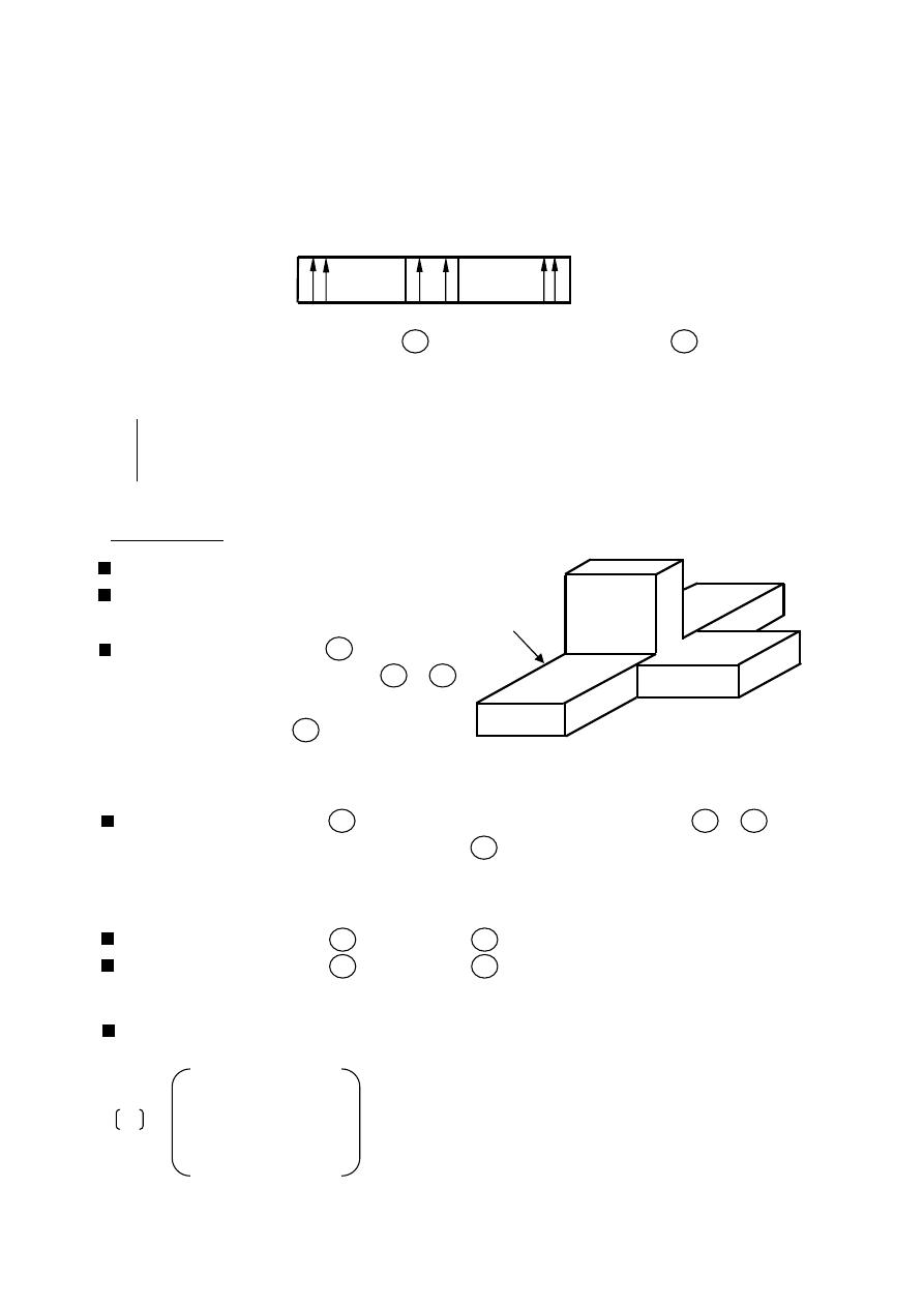
150
ﺎﺋﯿﺔــﺑﺮﮭﻜﻟا ﺔﺳﺪﻨﮭﻟا ﻢﺴﻗ ﻞــــﺻﻮﻤﻟا ﺔﻌﻣﺎﺟ
ﺎﻻتــﺼﺗﻻاو ﻚـــﯿﻧوﺮﺘﻜﻟﻻا عﺮـــــــــــــــﻓ
ﺎروديــﺒﻟا ﺪﻤﺤﻣ ﺪﯾﺆﻣ ناوﺮﻣ ﺐﻟﺎﻄﻟا داﺪﻋا
The scattering matrix of the H-plane T is given by
[
S] =
S
S
S
S
S
S
S
S
S
⟹
S
S
S
S
S
S
when the wave is incident at port 2 will result in waves at port 1 and with the same
direction
S
= S
[
S] =
S
S
S
S
S
S
S
S
S
(Hybrid Tee)
Magic Tee
Magic Tee is a four port network .
It can be considered as combination
of the E-plane & H-plane Tees.
A wave incident at port 4 (E arm)
divides equally between ports 2 & 3
and in opposite direction
(no coupling to port 1 )
S
= −S
S
= 0
A wave incident at port 1 (H arm) divides equally between port 2 & 3 and in
The same direction (no coupling to port 4 )
S
= S
S
= 0
A wave incident at port 2 zero at port 3
A wave incident at port 3 zero at port 2
S
= S
= 0
All the ports are matched
S
= S
= S
= S
= 0
0
S
S
S
0
0
S
0
0
0
S
S
0
S
S
0
=
=
Port 2
Port 3
Port 1
H-plane
Port 2
Port 3
Port 4
Port 1
H arm
E arm
Collinear
arms
S
=
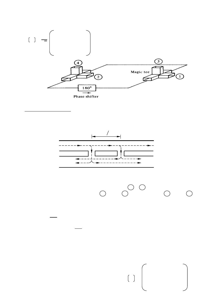
151
ﺎﺋﯿﺔــﺑﺮﮭﻜﻟا ﺔﺳﺪﻨﮭﻟا ﻢﺴﻗ ﻞــــﺻﻮﻤﻟا ﺔﻌﻣﺎﺟ
ﺎﻻتــﺼﺗﻻاو ﻚـــﯿﻧوﺮﺘﻜﻟﻻا عﺮـــــــــــــــﻓ
ﺎروديــﺒﻟا ﺪﻤﺤﻣ ﺪﯾﺆﻣ ناوﺮﻣ ﺐﻟﺎﻄﻟا داﺪﻋا
For an ideal magic Tee , the scattering matrix is
√
0 1
1
1 0
0
1 0
0
0
1
−1
0 1 −1 0
Directional Coupler
Directional coupler are four port components consisting of two waveguides coupled
together number of opening in a common wall
When all ports are terminated in their characteristic impedances , there is free
transmission of power without reflection between 1 & 2 and there is no
transmission of power between port 1 & port 3 or between port 2 & port 4 .
there directional coupler can be used to sample the power of a wave traveling
in a given direction in a waveguide system.
= 10
1
4
Directivity
= 10
4
3
For
= 0
⟹
= ∞ ideal case
For practical D.C
= 40 dB
Scattering matrix ( assume ideal D.C )
1- |
S | = |S | = 0 , |S | = |S | = 0
2- Assuming that the D.C is reciprocal 0 S 0 S
S 0 S 0
|
S | = |S | = |S | = |S |
3- for D.C (All the ports have matched loads) 0 S 0 S
S 0 S 0
|
S | = |S | = |S | = |S | = 0
S
=
Port 1
Port 3
Port 2
Port 4
Added
waveguide
waveguide
Primary
Secondary
Canceled
4
12
14
41
43
32
34
23
21
S =
A four-port circulator
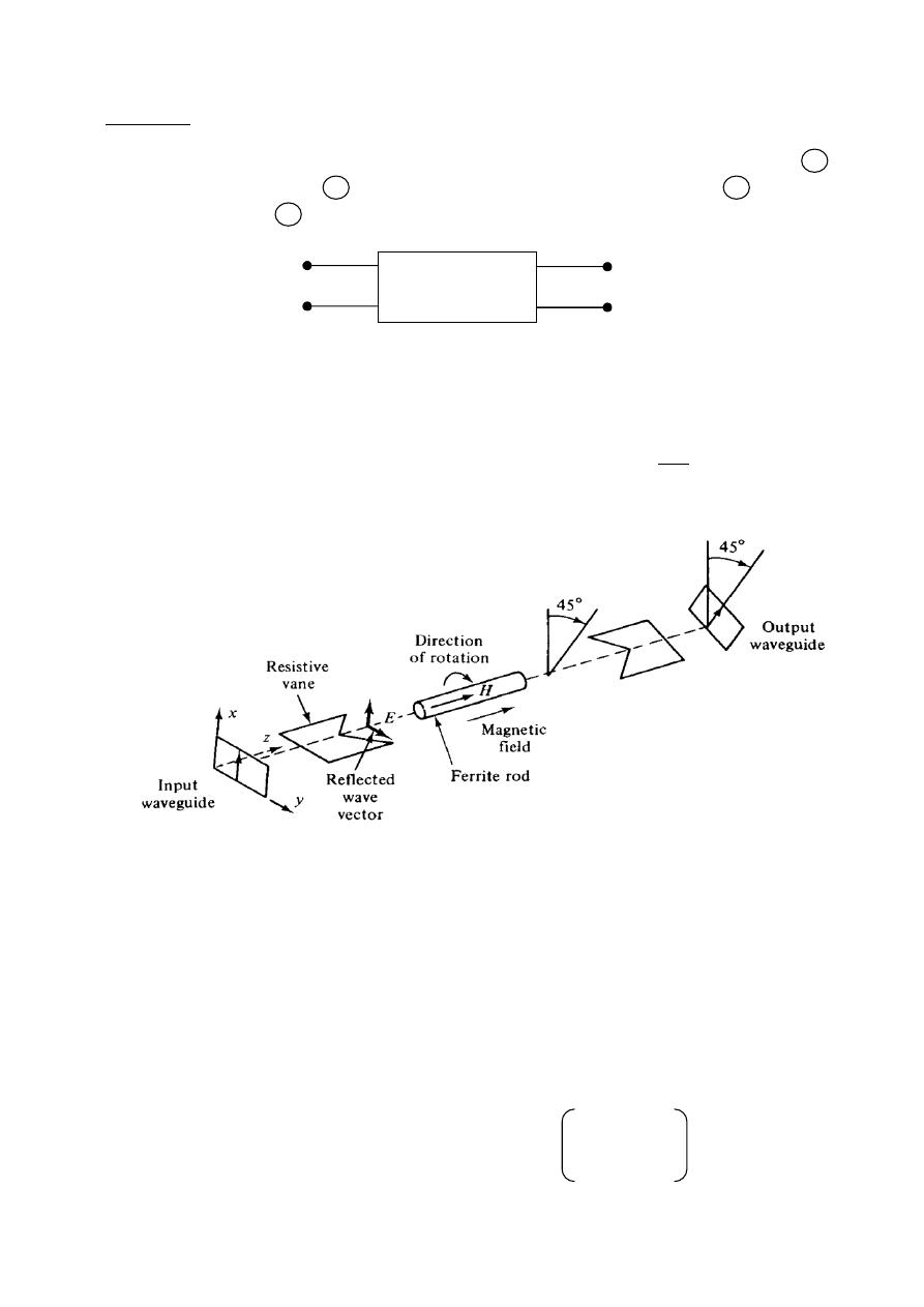
152
ﺎﺋﯿﺔــﺑﺮﮭﻜﻟا ﺔﺳﺪﻨﮭﻟا ﻢﺴﻗ ﻞــــﺻﻮﻤﻟا ﺔﻌﻣﺎﺟ
ﺎﻻتــﺼﺗﻻاو ﻚـــﯿﻧوﺮﺘﻜﻟﻻا عﺮـــــــــــــــﻓ
ﺎروديــﺒﻟا ﺪﻤﺤﻣ ﺪﯾﺆﻣ ناوﺮﻣ ﺐﻟﺎﻄﻟا داﺪﻋا
Isolators
Isolator is non reciprocal two port component allowing a wave incident on port 1
to be transmitted to port 2 , but not allowing a wave incident on port 2 to be
transmitted to port 1
Application : is prevent power being reflected back to a source .
For ideal |
S | = 1 forward (insertion loss)
|
S | = 0 reverse (isolation)
insertion loss
= −20
|S |
⟹
insertion loss
= 10
1
2
isolation
= −20
|S |
Ex:-
Find the scattering coefficient for a matched isolator with 1dB insertion loss
and 30dB isolation.
The solution:- |
S | = |S | = 0
⟹
match
insertion loss
= −20
|S |
1 = −20
|S |
|
S | = 0.89
isolation
= −20
|S |
30 = −20
|S |
|
S | = 0.032
Isolator
0.89
0.032
0
0
Faraday-rotation isolator
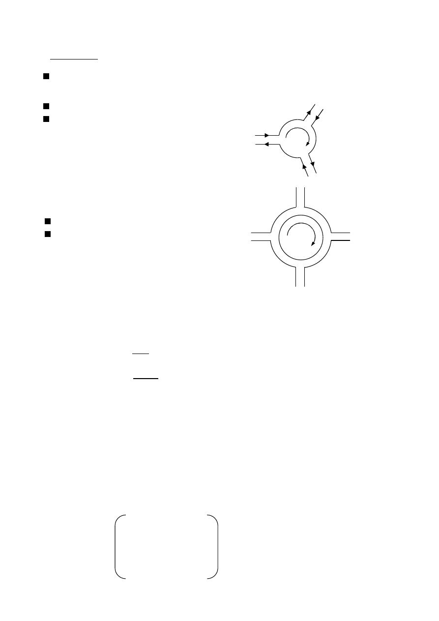
153
ﺎﺋﯿﺔــﺑﺮﮭﻜﻟا ﺔﺳﺪﻨﮭﻟا ﻢﺴﻗ ﻞــــﺻﻮﻤﻟا ﺔﻌﻣﺎﺟ
ﺎﻻتــﺼﺗﻻاو ﻚـــﯿﻧوﺮﺘﻜﻟﻻا عﺮـــــــــــــــﻓ
ﺎروديــﺒﻟا ﺪﻤﺤﻣ ﺪﯾﺆﻣ ناوﺮﻣ ﺐﻟﺎﻄﻟا داﺪﻋا
irculator
C
Circulators are multiport components that have the property then an incident wave
will be coupled only to adjacent port and to no others.
The circulator is non reciprocal device.
For three port circulator.
[
S] =
0
0
S
S
0
0
0
S
0
Application : for a 4-port circulator
Antenna works as Tx & Rx antenna
Matched load prevents reflected wave
From Rx to go to Tx
(despensaple if Rx is well designed)
Ex:-
the specification of a three port circulator are given as insertion loss =1dB
Isolation = 25dB and VSWR = 1.4 characterize the circulator by its
S-parameters
The solution:-
=
S−1
S+1
=
1.4−1
1.4+1
= 0.17
S
= S
= S
=
= 0.17
insertion loss
= −20
|S |
1 = −20
|S |
|
S | = 0.89
S
= S
= S
= 0.89
isolation
= −20
|S |
25 = −20
|S |
|
S | = 0.056
S
= S
= S
= 0.056
Port 2
Port 1
Port 3
Port 4
Port 2
Port 3
Port 1
0.89
0.17
0.17
0.17
0.89
0.89
0.056
0.056
0.056
Antenna
Receiver
Match load
Transmitter
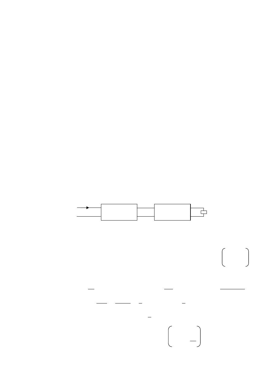
154
ﺎﺋﯿﺔــﺑﺮﮭﻜﻟا ﺔﺳﺪﻨﮭﻟا ﻢﺴﻗ ﻞــــﺻﻮﻤﻟا ﺔﻌﻣﺎﺟ
ﺎﻻتــﺼﺗﻻاو ﻚـــﯿﻧوﺮﺘﻜﻟﻻا عﺮـــــــــــــــﻓ
ﺎروديــﺒﻟا ﺪﻤﺤﻣ ﺪﯾﺆﻣ ناوﺮﻣ ﺐﻟﺎﻄﻟا داﺪﻋا
Ex:-
the scattering matrix of the three port circulator is given by:
[
S] =
0
0
0.84
0.84
0.2
0
0
0.84
0
If the input power to port 1 is 10 mW , find the net power at ports 2 , and 3.
The solution:-
S
= S
= S
= 0.84 , S
= 0.2
⟹
= 0.2
= |S |
= |0.84| × 0.01 = 7.056 mW
= |S |
= |0.2| × 7.056 × 10
= 0.28 mW
(
)
=
−
= 7.056 × 10
− 0.28 × 10
= 6.776 mW
= |S |
= |0.84| × 0.28 × 10
= 0.1975 mW
= |S |
= |0| × 0.1975 × 10
= 0 W
(
)
=
−
(
)
= 0.1975 × 10
− 0
(
)
= 0.1975 mW
Ex:-
For the following microwave circuit , determine the net power at the load
And the scattering matrix of the microwave circuit.
The solution:- Isolator
insertion loss
= −20
|S |
⟹
1 = −20
|S |
⟹
|S | = 0.89
= |S |
⟹
= |0.89| × 10 × 10
= 7.9 mW
isolation
= −20
|S |
⟹
20 = −20
|S |
⟹
|S | = 0.1
Attenuator (i/p power for Attenuator
=
= )
Attenuation
= 10
1
2
⟹
Attenuation
= 10
2
⟹
10 = 10
7.9×10
−3
2
= 0.79 mW ,
=
S−1
S+1
=
1.4−1
1.4+1
=
1
6
|S | =
=
1
6
, where |
S | = 0
(
)
=
− | |
= 0.79 × 10
−
1
6
× 0.79 × 10
= 0.77 mW
10 = −20
|S |
⟹
|S | = 0.316
|
S | = |S | = 0.316
0.89
0.1
0
0
0
0.316
0.316
1
6
Attenuator
Isolator
Load
VSWR
=1.4
10 dB
Insertion loss = 1dB
Isolation = 20dB
Matched
P
i
= 10 mW
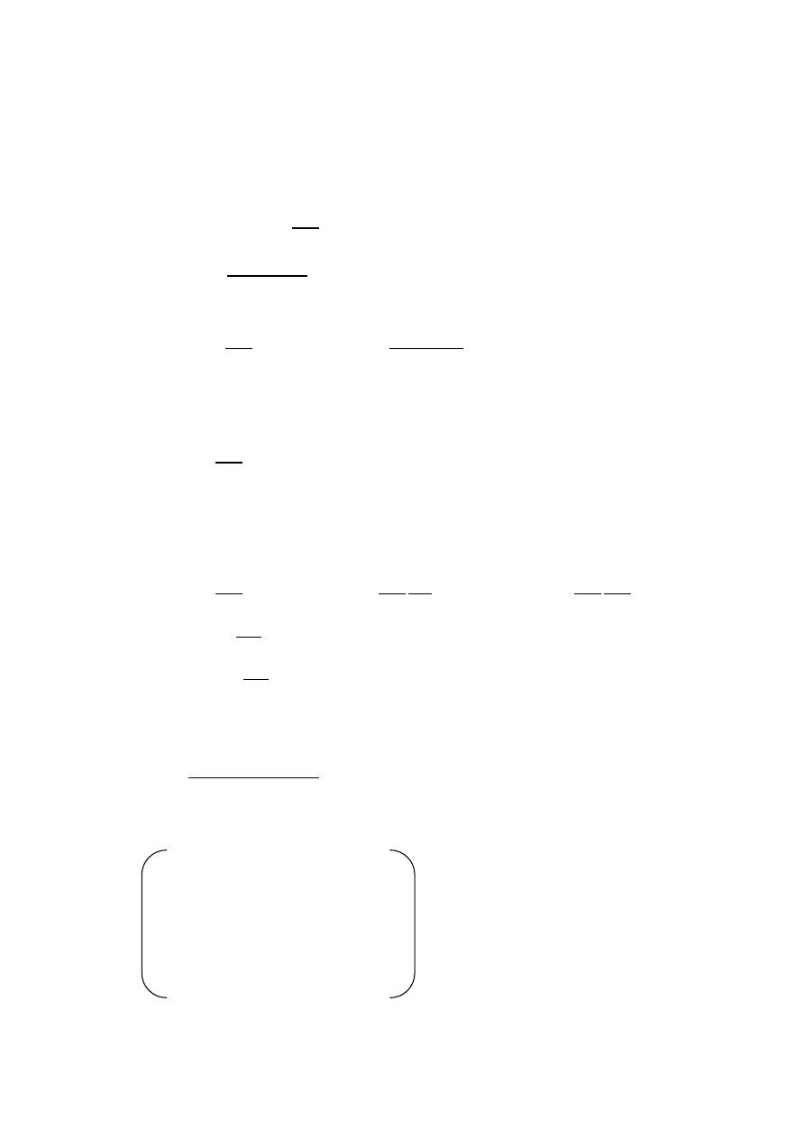
155
ﺎﺋﯿﺔــﺑﺮﮭﻜﻟا ﺔﺳﺪﻨﮭﻟا ﻢﺴﻗ ﻞــــﺻﻮﻤﻟا ﺔﻌﻣﺎﺟ
ﺎﻻتــﺼﺗﻻاو ﻚـــﯿﻧوﺮﺘﻜﻟﻻا عﺮـــــــــــــــﻓ
ﺎروديــﺒﻟا ﺪﻤﺤﻣ ﺪﯾﺆﻣ ناوﺮﻣ ﺐﻟﺎﻄﻟا داﺪﻋا
Ex:-
The input power to a directional coupler is 120 mW .the coupling coefficient is
20 dB and the directivity is 40 dB. Assuming that the coupler is lossless and
that all the ports have matched loads.
1- Find the output power for ports 2,3 and 4.
2- Characterize the coupler by its S-parameters.
The solution:-
= 10
1
4
1-
20 = 10
120×10
−3
4
= 1.2 mW
= 10
4
3
⟹
40 = 10
1.2×10
−3
3
= 0.12 W
=
−
−
= 120 × 10
− 1.2 × 10
− 0.12 × 10
= 118.8 mW
2-
= 10
1
4
⟹
= −20
|S |
20 = −20
|S |
⟹
|S | = 0.1
|
S | = |S | = |S | = |S | = 0.1
|
S | = |S | = |S | = |S | = 0
= 10
4
3
⟹
= 10
4
3
1
1
⟹
= 10
1
3
4
1
= −20
31
41
40 = −20
31
0.1
⟹
|S | = 0.001
|
S | = |S | = |S | = |S | = 0.001
S S
∗
+ S S
∗
+ S S
∗
+ S S
∗
= 1
0 × 0 + S
2
+ 0.001 + 0.1 = 1
S
= √1 − 0.01 − 10
= 0.99
|
S | = |S | = |S | = |S | = 0.99
0 0.99 0.001 0.1
0.99 0 0.1 0.001
0.001 0.1 0 0.99
0.1 0.001 0.99 0
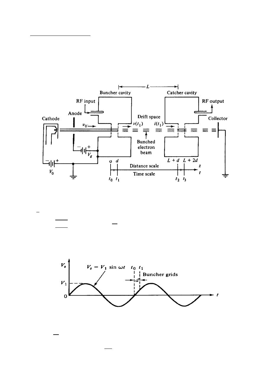
156
ﺎﺋﯿﺔــﺑﺮﮭﻜﻟا ﺔﺳﺪﻨﮭﻟا ﻢﺴﻗ ﻞــــﺻﻮﻤﻟا ﺔﻌﻣﺎﺟ
ﺎﻻتــﺼﺗﻻاو ﻚـــﯿﻧوﺮﺘﻜﻟﻻا عﺮـــــــــــــــﻓ
ﺎروديــﺒﻟا ﺪﻤﺤﻣ ﺪﯾﺆﻣ ناوﺮﻣ ﺐﻟﺎﻄﻟا داﺪﻋا
ystron
Cavity Kl
Two
Characteristics:-
1-
= 40%
2- output power contains wave is up to 500 Km pulsed power is up to 30MW at
10 GHz.
3- power gain about 30dB.
1- Velocity Modulation Process.
m
2
=
=
2
m
= 0.593 × 10
mps
The gap voltage between buncher grids (signal voltage)
=
≪
Let
−
=
=
=
=
(
−
)
=
rad
Two cavity klystron amplifier
Signal voltage in the average gap transit angle
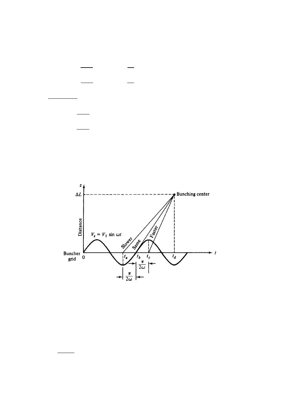
157
ﺎﺋﯿﺔــﺑﺮﮭﻜﻟا ﺔﺳﺪﻨﮭﻟا ﻢﺴﻗ ﻞــــﺻﻮﻤﻟا ﺔﻌﻣﺎﺟ
ﺎﻻتــﺼﺗﻻاو ﻚـــﯿﻧوﺮﺘﻜﻟﻻا عﺮـــــــــــــــﻓ
ﺎروديــﺒﻟا ﺪﻤﺤﻣ ﺪﯾﺆﻣ ناوﺮﻣ ﺐﻟﺎﻄﻟا داﺪﻋا
: time each electron spends in gap region.
d: gap spacing in either cavity.
: gap transient.
( ) =
1 +
1
2
+
2
( ) =
1 +
1
2
−
2
=
(
/2)
/2
=
1 +
1
2
=
1 −
1
2
: beam coupling coefficient of the input cavity.
: amplitude of input signal.
: DC beam voltage.
2- Bunching Process
∆L =
(
−
)
∆L =
(
−
)
∆L =
(
−
)
∆L: the distance from the buncher grids to the location of dense electron bunching.
The necessary condition for those electrons at , , to meet at the same distance
∆L =
1
Signal voltage in the buncher gap
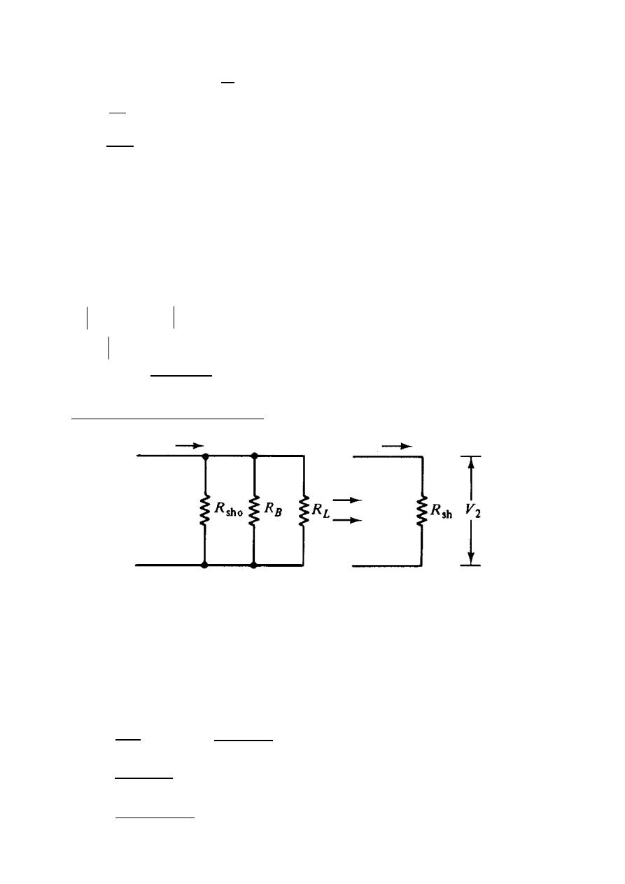
158
ﺎﺋﯿﺔــﺑﺮﮭﻜﻟا ﺔﺳﺪﻨﮭﻟا ﻢﺴﻗ ﻞــــﺻﻮﻤﻟا ﺔﻌﻣﺎﺟ
ﺎﻻتــﺼﺗﻻاو ﻚـــﯿﻧوﺮﺘﻜﻟﻻا عﺮـــــــــــــــﻓ
ﺎروديــﺒﻟا ﺪﻤﺤﻣ ﺪﯾﺆﻣ ناوﺮﻣ ﺐﻟﺎﻄﻟا داﺪﻋا
=
where
=
=
X =
1
2
: DC transit angle between cavities.
L: spacing between centers of cavities.
X: bunching parameter.
The fundamental component of the beam current at the catcher cavity
has a magnitude
(
) = 2
( ) where : input DC current
=
identical cavities
= 2
( )
( )
= 0.582 at = 1.841
=
3.682
1
Output power and efficiency
: the wall resistance of the catcher cavity.
: beam coupling resistance.
: external load resistance.
=
//
//
,
: the effective shunt resistance
=
(
) ×
= 2
( )
=
,
=
2 2
(
)
2
,
=
=
2 2
(
)
2
=
2
1
( )
2
2
× 100%
max
max
max
Output equivalent circuit
I
2
(ind)
I
2
(ind)

159
ﺎﺋﯿﺔــﺑﺮﮭﻜﻟا ﺔﺳﺪﻨﮭﻟا ﻢﺴﻗ ﻞــــﺻﻮﻤﻟا ﺔﻌﻣﺎﺟ
ﺎﻻتــﺼﺗﻻاو ﻚـــﯿﻧوﺮﺘﻜﻟﻻا عﺮـــــــــــــــﻓ
ﺎروديــﺒﻟا ﺪﻤﺤﻣ ﺪﯾﺆﻣ ناوﺮﻣ ﺐﻟﺎﻄﻟا داﺪﻋا
For perfect coupling
= 1
=
(
)
= 2
(1.841) = 2
× 0.582
=
=
2
1
( )
2
2
× 100%
=
2(1) (0.582)
2
× 100% = 58.2%
=
2
1
=
2
1
( )
ℎ
1
Ex:-
A two-cavity Klystron amplifier has the following parameters
= 1000 V ,
= 40 kΩ ,
= 25 mA , = 3 GHz
Gap spacing in either cavity (d) = 1mm and spacing between the two cavity
(L) =4cm , Effective shunt impedance excluding beam loading
= 30 kΩ
1- find the input gap voltage to give maximum voltage
2- find the voltage gain & efficiency of the amplifier.
The solution:- The solution:- for maximum
,
( ) must be maximum
This means ( )
= 0.582 at = 1.841
1-
= 0.593 × 10
= 0.593 × 10 √1000 = 1.88 × 10 mps
=
= 2 × 3 × 10
10
−3
1.88×10
7
= 1 rad
=
=
(
/2)
/2
=
(
1/2)
1/2
= 0.958
=
= 2 × 3 × 10
4×10
−2
1.88×10
7
= 40 rad
=
2
=
2 1000 (1.841)
0.958 40
= 96 V
2-
=
2
1
=
836
96
= 8.7
(
) = 2
( )
(
) = 2(0.958)(25 × 10 )(0.582) = 27.88 mA
= 2
( )
= 2(0.958)(25 × 10 )(0.582)(30 × 10 ) = 836 V
=
2 2
(
)
2
=
(
836
)
(27.88×10
−3
)
2(1000)(25×10
−3
)
× 100% = 46.6%

160
ﺎﺋﯿﺔــﺑﺮﮭﻜﻟا ﺔﺳﺪﻨﮭﻟا ﻢﺴﻗ ﻞــــﺻﻮﻤﻟا ﺔﻌﻣﺎﺟ
ﺎﻻتــﺼﺗﻻاو ﻚـــﯿﻧوﺮﺘﻜﻟﻻا عﺮـــــــــــــــﻓ
ﺎروديــﺒﻟا ﺪﻤﺤﻣ ﺪﯾﺆﻣ ناوﺮﻣ ﺐﻟﺎﻄﻟا داﺪﻋا
Ex:-
A two-cavity amplifier klystron has the following parameters:
Beam voltage :
= 900 V
Beam current :
= 30 mA
Frequency :
= 8 GHz
Gap spacing in either cavity :
= 1 mm
Spacing between centers of cavities: L = 4 cm
Effective shunt impedance:
= 40kΩ
Determine:
a- The electron velocity.
b- the dc transient time of electron.
c- The input voltage for maximum output voltage.
d- The voltage gain in decibels & efficiency of the amplifier.
The solution:- for maximum
,
( ) must be maximum
This means ( )
= 0.582 at = 1.841
a-
= 0.593 × 10
= 0.593 × 10 √900 = 17.79 × 10 mps
b-
=
,
= 4 × 10
− 2
10
−3
2
= 3.9 cm
=
= 2 × 8 × 10
3.9×10
−2
17.79×10
6
= 110.2 rad
c-
=
= 2 × 8 × 10
10
−3
17.79×10
6
= 2.825 rad
=
(
/2)
/2
=
(
2.825/2)
2.825/2
= 0.699
=
2
=
2 900 (1.841)
0.699 110.2
= 43 V
d- (
) = 2
( )
(
) = 2(0.699)(30 × 10 )(0.582) = 24.4 mA
= 2
( )
= 2(0.699)(30 × 10 )(0.582)(40 × 10 ) = 976 V
=
2
1
=
976
43
= 22.7
=
2 2
(
)
2
=
(
976
)
(24.4×10
−3
)
2(900)(30×10
−3
)
× 100% = 44%

161
ﺎﺋﯿﺔــﺑﺮﮭﻜﻟا ﺔﺳﺪﻨﮭﻟا ﻢﺴﻗ ﻞــــﺻﻮﻤﻟا ﺔﻌﻣﺎﺟ
ﺎﻻتــﺼﺗﻻاو ﻚـــﯿﻧوﺮﺘﻜﻟﻻا عﺮـــــــــــــــﻓ
ﺎروديــﺒﻟا ﺪﻤﺤﻣ ﺪﯾﺆﻣ ناوﺮﻣ ﺐﻟﺎﻄﻟا داﺪﻋا
Ex:-
A two cavity klystron amplifier has the following parameters:
= 1200 V
= 28 mA , = 5 GHz , gap spacing in either = 1mm , spacing between
the cavities = 4cm , shunt resistance of output cavity = 60k
Ω , load resistance
of output cavity = 60k
Ω , and the peak input voltage = 50 volt . determine
1- The time the electrons are in the gap.
2- The efficiency of the amplifier.
3- The voltage gain.
4- The range of the velocities of electrons as they leave the gap region.
5- The power delivered to the load.
The solution:-
= 1200 V ,
= 28 mA , = 5 GHz , d =1mm , L = 4cm
= 60kΩ ,
= 60kΩ ,
= 50 V
1-
= 0.593 × 10
= 0.593 × 10 √1200 = 20.54 × 10 mps
=
=
0.001
20.54×10
6
= 48.68 Psec
2-
=
= 2 × 5 × 10
10
−3
20.54×10
6
= 1.53 rad
=
(
/2)
/2
=
(
1.53/2)
1.53/2
= 0.905
=
= 2 × 5 × 10
4×10
−2
20.54×10
6
= 61.18 rad
X =
1
2
=
0.905×50
2×1200
61.18 = 1.153 from table ( ) = 0.485
=
//
= 30kΩ
= 2
( )
= 2(0.905)(28 × 10 )(0.485)(30 × 10 ) = 737.4 V
(
) = 2
( ) = 2(0.905)(28 × 10 )(0.485) = 24.6 mA
=
2 2
(
)
2
=
(
737.4
)
(24.6×10
−3
)
2(1200)(28×10
−3
)
× 100% = 26.99%
3-
=
2
1
=
737.4
50
= 14.748
4-
=
1 +
1
2
= 20.54 × 10 1 +
0.905×50
2×1200
= 20.92 × 10 m/s
=
1 −
1
2
= 20.54 × 10 1 −
0.905×50
2×1200
= 20.15 × 10 m/s
5-
=
(
)
ℎ
ℎ
+
= 24.6 × 10
60×10
3
60×10
3
+60×10
3
= 12.3 mA
=
2
2
=
12.3×10
−3 2
×60×10
3
2
= 4.5 W

162
ﺎﺋﯿﺔــﺑﺮﮭﻜﻟا ﺔﺳﺪﻨﮭﻟا ﻢﺴﻗ ﻞــــﺻﻮﻤﻟا ﺔﻌﻣﺎﺟ
ﺎﻻتــﺼﺗﻻاو ﻚـــﯿﻧوﺮﺘﻜﻟﻻا عﺮـــــــــــــــﻓ
ﺎروديــﺒﻟا ﺪﻤﺤﻣ ﺪﯾﺆﻣ ناوﺮﻣ ﺐﻟﺎﻄﻟا داﺪﻋا
Ex:-
A two cavity klystron amplifier has the following parameters:
= 1200 V
= 40k
Ω , = 5 GHz , d = 1mm , L = L
= 4cm , shunt resistance
of the output cavity = 60k
Ω and load resistance of the output cavity = 60kΩ
determine:
1- The catcher cavity voltage.
2- The efficiency of the amplifier .
3- The voltage gain.
4- The distance from the buncher grid to the location of dense electrons.
The solution:-
= 1200 V ,
= 40KΩ , = 5GHz , d =1mm
L =
L
= 4cm
= 60kΩ ,
= 60kΩ
1-
= 0.593 × 10
= 0.593 × 10 √1200 = 20.54 × 10 m/s
=
= 2 × 5 × 10
10
−3
20.54×10
6
= 1.53 rad
=
= 2 × 5 × 10
4×10
−2
20.54×10
6
= 61.18 rad
=
(
/2)
/2
=
(
1.53/2)
1.53/2
= 0.905
=
3.682
1
⟹
=
3.682
=
3.682×20.54×10
6
×1200
2 ×5×10
9
×0.905×4×10
−2
= 79.8 V
X =
1
2
=
0.905×79.8
2×1200
61.18 = 1.84 from table ( ) = 0.582
=
//
= 30kΩ
=
=
1200
40×10
3
= 30 mA
= 2
( )
= 2(0.905)(30 × 10 )(0.582)(30 × 10 ) = 948 V
2- (
) = 2
( ) = 2(0.905)(30 × 10 )(0.582) = 31.6 mA
=
2 2
(
)
2
=
(
948
)
(31.6×10
−3
)
2(1200)(30×10
−3
)
× 100% = 41.6%
3-
=
2
1
=
948
79.8
= 11.88
4-
∆L =
1
= 20.54 × 10
×1200
2 ×5×10
9
×0.905×79.8
= 0.034 m