
1
Electronic II
Topics
1. Differential Amplifier
2. Differential Amplifier Applications
3. Operation amplifier internal circuits
4. Inverting and non-inverting amplifier
5. Differentiator and integrator circuits
6. A/D and D/A convertors
7. Logarithmic amplifier
8. Analog computer circuits
9. Power amplifiers
10. Heat sink design
11. Negative Feedback
12. Amplifier instability
13. Transistor amplifier frequency response
14. RF amplifiers circuits
15. oscillators circuits types
16. Mixers
17. PLL and frequency synthesizers
18. Power supply regulator and switched mode
19. Switched capacitor circuits and filter
References
1. electronic devices by floyd 7
th
2. Microelectronics Circuit Analysis and Design Donald A. Neamen
2
1.1 Differential Amplifier
1. Direct coupling
2. Low Noise
3. High input impedance
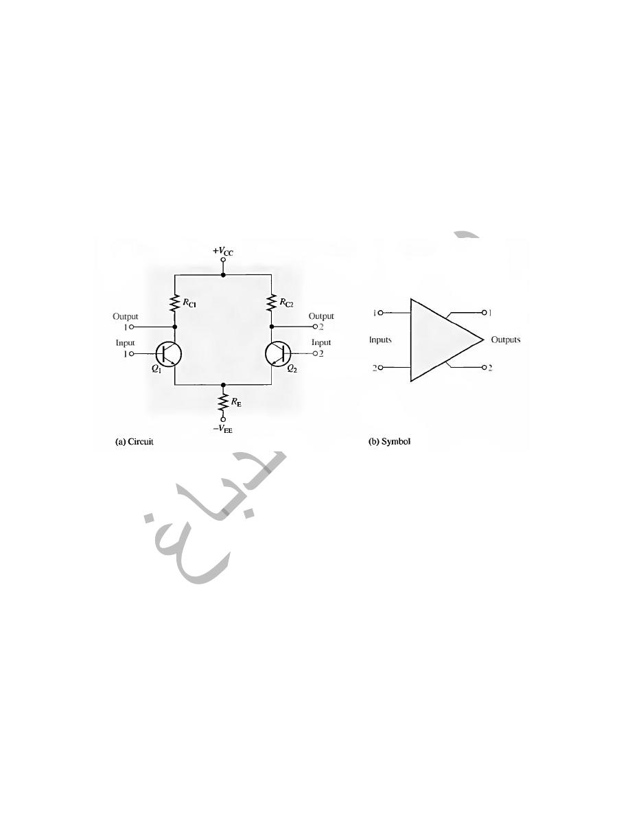
A differential amplifier is a BJT amplifier that produces outputs that are a
function of the difference between two input voltages.
Basic Operation
when both inputs are grounded (0 V), the emitters are at 0.7 V, It is assumed
that the transistors are identically matched by careful process control during
manufacturing so that their dc emitter currents are the same when there is no
input signal. Thus,
3
4
1.2Modes of Signal Operation
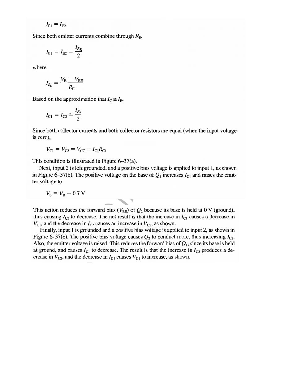
1- Single-Ended Differential Input When a diff-amp is operated with
this input configuration, one input is grounded and the signal voltage is
applied only to the other input, as shown in Figure 6–39. In the case
where the signal voltage is applied to input 1 as in part (a), an inverted,
amplified signal voltage appears at output 1 as shown. Also, a signal
voltage appears in phase at the emitter of Q1. Since the emitters of Q1
and Q2 are common, the emitter signal becomes an input to Q2, which
functions as a common-base amplifier. The signal is amplified by Q2 and
appears, noninverted, at output 2. This action is illustrated in part (a).
In the case where the signal is applied to input 2 with input 1 grounded,
as in Figure 6–39(b), an inverted, amplified signal voltage appears at
output 2. In this situation, Q1 acts as a common-base amplifier, and a
noninverted, amplified signal appears at output 1.
5
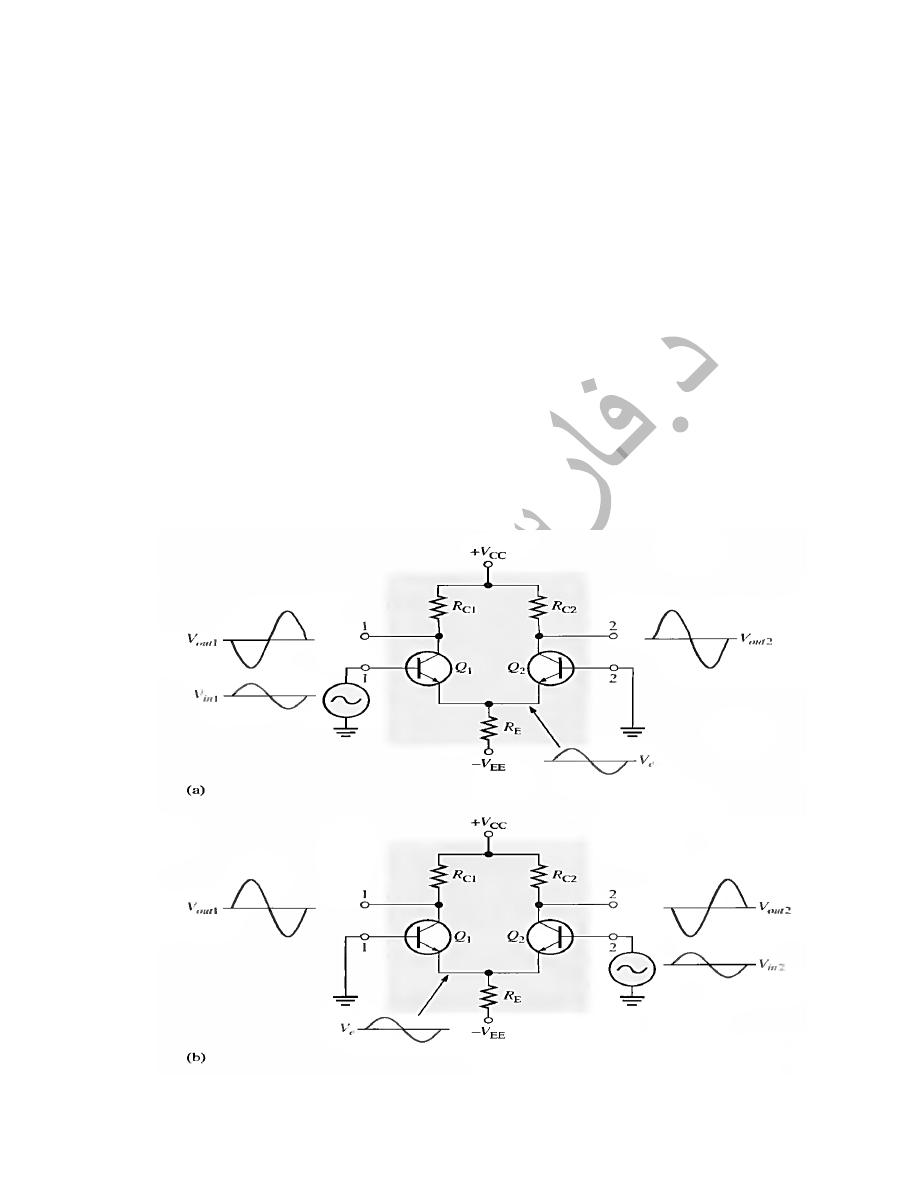
2- Double-Ended Differential Inputs In this input configuration, two
opposite-polarity (out-of-phase) signals are applied to the inputs, as
shown in Figure 6–40(a). Each input affects the outputs, as you will see
in the following discussion. Figure 6–40(b) shows the output signals due
to the signal on input 1 acting alone as a single-ended input. Figure 6–
40(c) on page 308 shows the output signals due to the signal on input 2
acting alone as a single-ended input. Notice in parts (b) and (c) that the
signals on output 1 are of the same polarity. The same is also true for
output 2. By superimposing both output 1 signals and both output 2
signals, you get the total output signals, as shown
6
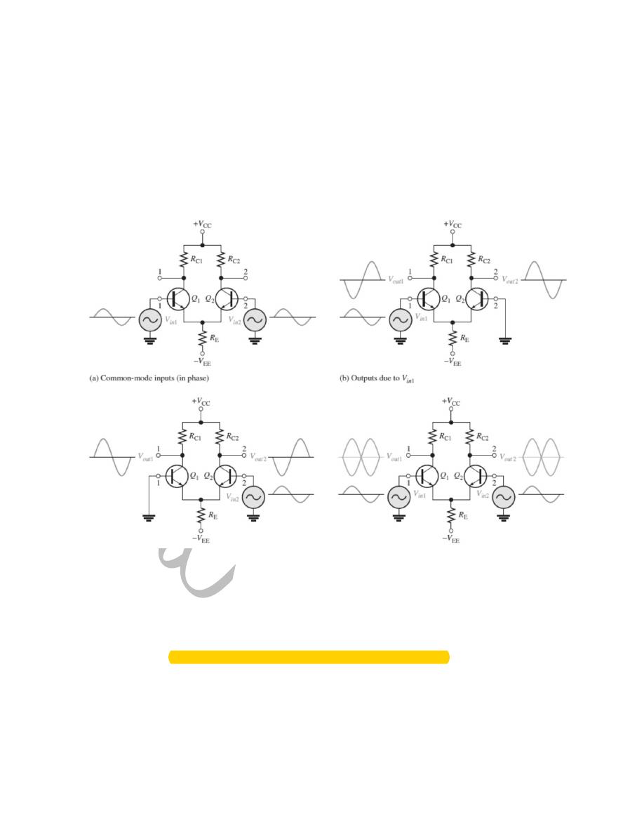
3- Common-Mode Inputs One of the most important aspects of the
operation of a diffamp can be seen by considering the common-mode
condition where two signal voltages of the same phase, frequency, and
amplitude are applied to the two inputs, as shown in Figure 6–41(a).
Again, by considering each input signal as acting alone, you can
understand the basic operation.
Figure 6–41(b) shows the output signals due to the signal on only
input 1, and Figure6–41(c) shows the output signals due to the signal on only
input 2. Notice that the corresponding signals on output 1 are of the opposite
polarity, and so are the ones on output 2.When the input signals are applied to
both inputs, the outputs are superimposed and they cancel, resulting in a zero
output voltage, as shown in Figure 6–41(d).This action is called common-mode
rejection. Its importance lies in the situation where an unwanted signal appears
commonly on both diff-amp inputs. Common-mode rejection means that this
unwanted signal will not appear on the outputs and distort the desired signal.
7
Common-mode signals (noise) generally are the result of the pick-up of
radiated energy on the input lines from adjacent lines, the 60 Hz power line, or
other sources.
4-Common-Mode Rejection Ratio
Desired signals appear on only one input or with opposite polarities on both
input lines. These desired signals are amplified and appear on the outputs as
previously discussed. Unwanted signals (noise) appearing with the same
polarity on both input lines are essentially cancelled by the diff-amp and do not
appear on the outputs. The measure of an amplifier’s ability to reject common-
mode signals is a parameter called the CMRR (commonmode rejection ratio).
Ideally, a diff-amp provides a very high gain for desired signals (single-ended
or differential)
and zero gain for common-mode signals. Practical diff-amps, however, do
exhibit a very small common-mode gain (usually much less than 1), while
providing a high differential voltage gain (usually several thousand). The
higher the differential gain with respect to the common-mode gain, the better
the performance of the diff-amp in terms of rejection of common-mode signals.
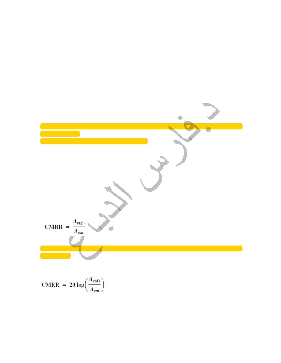
This suggests that a good measure of the diff-amp’s performance in rejecting
unwanted common-mode signals is the ratio of the differential voltage gain
Av(d ) to the common-mode gain, Acm. This ratio is the common-mode
rejection ratio, CMRR.
The higher the CMRR, the better. A very high value of CMRR means that the
differential
gain Av(d) is high and the common-mode gain Acm is low. The CMRR is often
expressed in decibels (dB) as
8
Example : A certain diff-amp has a differential voltage gain of Av(d ) =
2000 and a common-mode gain of Acm =0.2. Determine the CMRR and
express it in decibels.
Solution
Therefore,
CMRR = 20 log (10,000) = 80 dB
Comment
A CMRR of 10,000 means that the desired input signal (differential) is
amplified 10,000 times more than the unwanted noise (common-mode). For
example, if the amplitudes of the differential input signal and the common-
mode noise are equal, the desired signal will appear on the output 10,000 times
greater in amplitude than the noise. Thus, the noise or interference has been
essentially eliminated.
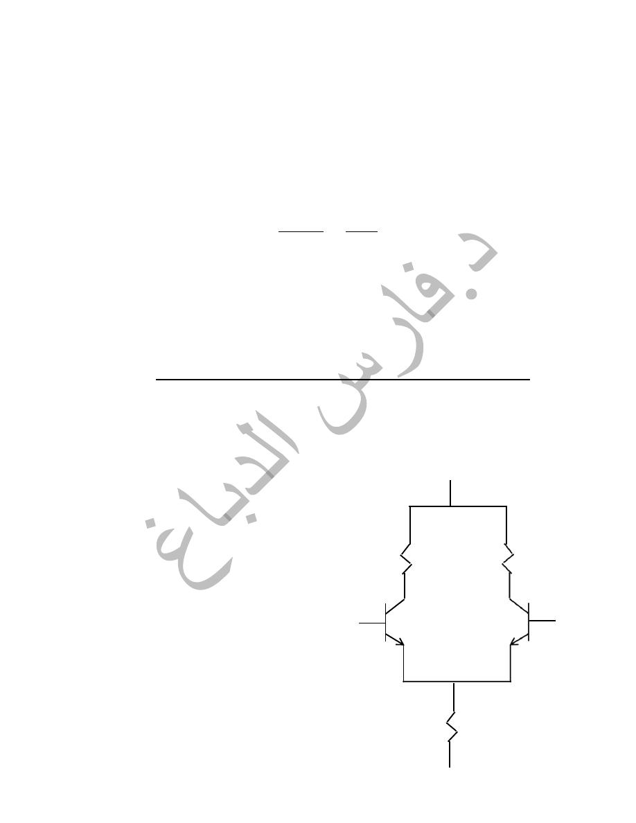
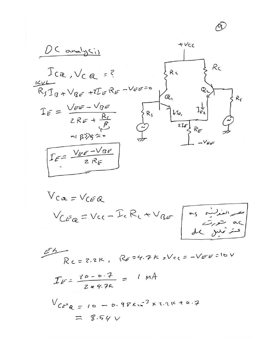
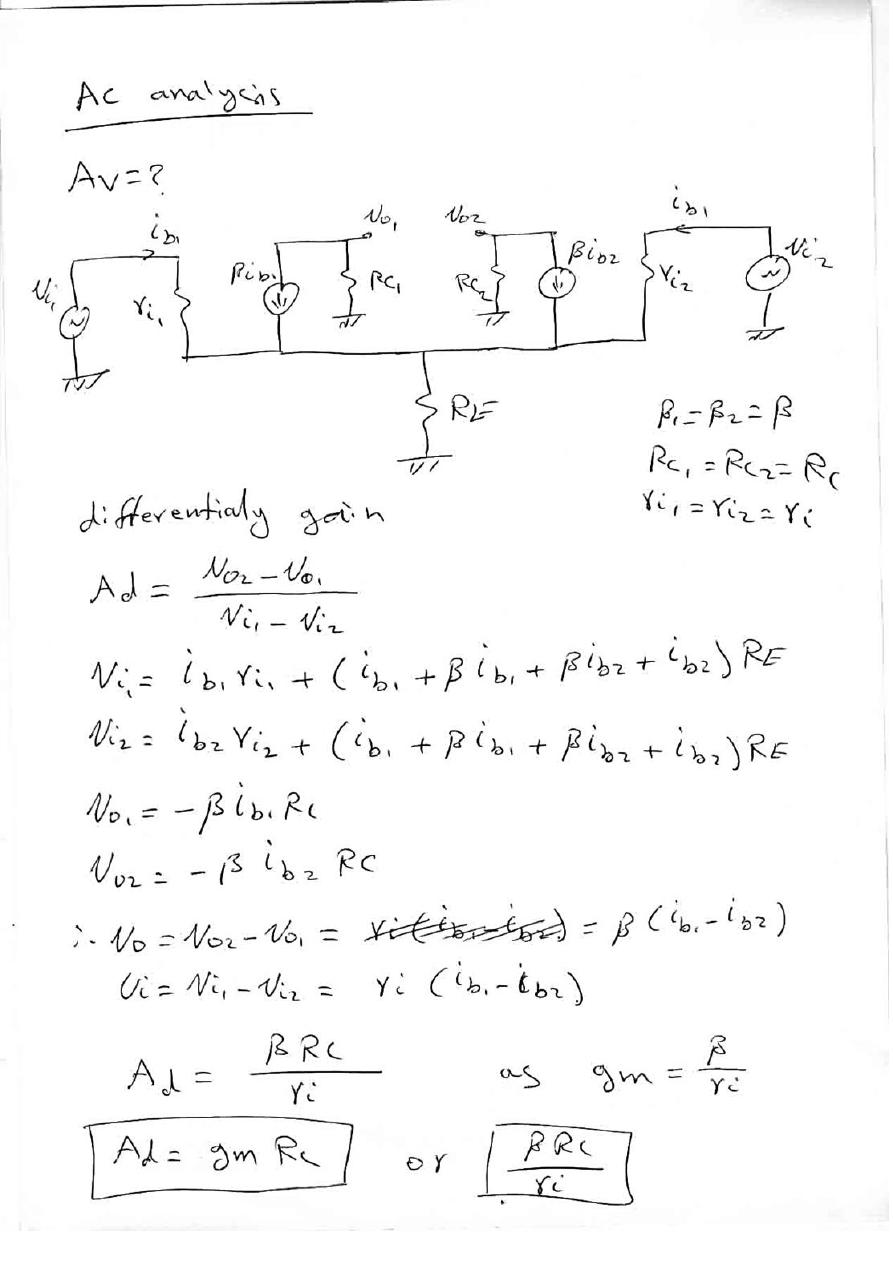
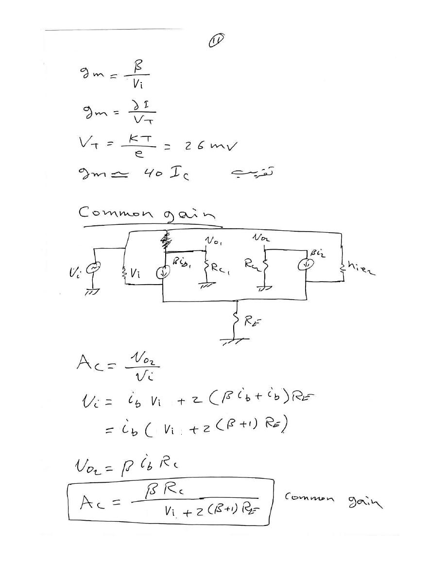
Differential amplifier DC analysis
9
11