Exp. (3)
Ohm`s Law
I. Objective:
1.to prove Ohm`s Law practically on the conductive elements when the
physical properties constant.
2. to study Ohm`s Law when the physical Properties inconstant.
II. Theoretical Background:
the current through the conductive elements when the physical properties
constant is directly proportional to the potential difference across the two
points.
The mathematical equation that describes this relationship is:
V α I
R * I ………..(1)
So If we apply several different voltages on a resistor (R1) with a
proper intervals and we record the value of the drawn currents according
to that voltages then, we will find that the rate between the voltage and
the current is constant and this rate is equal to the resistor (R1).and if we
repeat that process on the resistors R2,R3 …..etc, we will find other
constant rates equal to the resistors values R2,R3......etc sequentially will
be shown. We conclude from that the relationship in equation (1) is a
relationship of a straight line beginning from the origin point with a
slope angle (θ) equal to:
θ =
………….(2)
and the value of (R) equal to ( tan θ).
From the above it can be concluded that the resistor is a linear element
(no change in its value during the change of the voltage across it).
If we exchange the resistor with a lamp wick and we apply different
voltages you will find that the resistor value will change with the voltage
changing and this because of the change in the wick temperature, so if
we suppose that the initial temperature degree of the wick is (20
o
) and
the final degree is (T) then the resistor value will change to (RT)
according to the relationship:
RT =R20(1+ α(T-20)) ………..(3)
When (α) is the material heat Coefficient, it can be with a positive or a
negative value.
III. Apparatus
1. DC power supply.
2. Digital Multimeter.
3. Resistors 1KΩ , 2.2KΩ.
4. Small lamp 12V
IV. Procedure:-
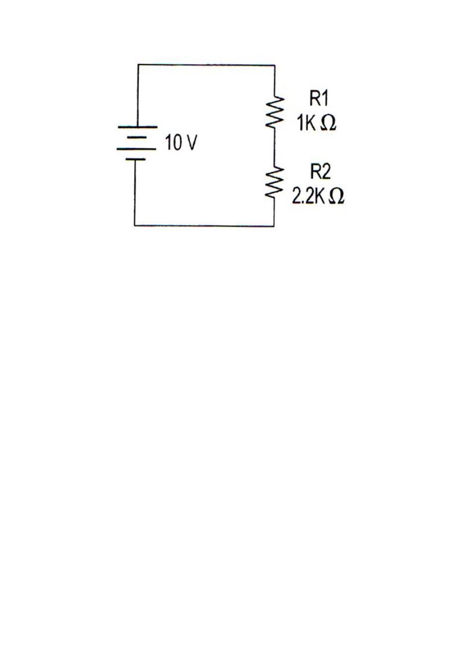
1. Connect the circuit shown in the next diagram.
2. Change the source voltage (0-10) volt by 1 volt interval and record
the drawn currents.
3. Exchange (R1) with (R2) and repeat step (2).
4. Exchange (R2) with Lamp and repeat step (2).
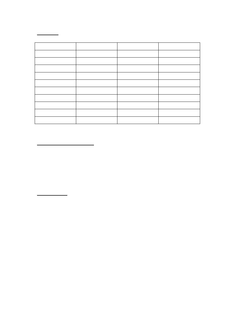
V. Results:
V(v)
I(1K
Ω)
I(2.2K
Ω)
I(Lamp)
1
2
3
4
5
6
7
8
9
10
VI. Graphical Diagrams:
1. On the same paper and on the same axis draw the
relationship between the current and the voltage for steps (2)
and (3).
2. For step (4) draw the relationship between the current and
the voltage.
VII. Discussion:
Q(1). Compare between the resistors values in the graphical
digram (1) and the original resistors values taking the
consideration of the tolerance of the used devices and if there is
any difference, comment on that?
Q.(2) generally the resistor considered as a linear element, can
we say that about the Lamp? And can we apply Ohm`s Law on
it?
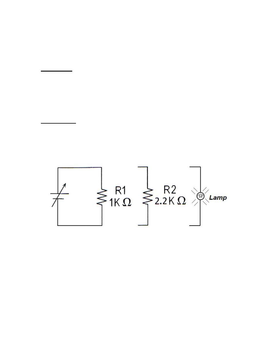
Q(3). In the circuit shown below, R1 value =1(K
Ω) with a
tolerance rate (20%) and R2
value =2.2(K
Ω)
with a tolerance rate
(
5%), find the maximum current can be move in this circuit
taking the consideration of the maximum error rates?