Lecture 2
Yazen H Shakir & Mohanad AL-Rekany
1
AutoCAD 201
6
Basics of Drawing or drafting (2D) in AutoCAD
Objectives:
Today, we are going to learn the following aspects:
Preparing the area of drawing.
Drawing Lines.
Circle drawing methods.
Practicing simple exercise.
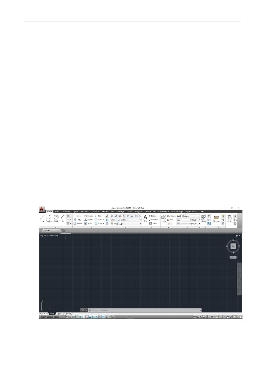
Starting Up AutoCAD 2014:
1. Select the AutoCAD 2014 option on the Program menu or select the AutoCAD 2014 icon
on the Desktop. Click Start Drawing to start a new drawing.
Note that AutoCAD automatically assigns generic names, Drawing X, as new drawings are
created. In our example, AutoCAD opened the graphics window using the default system units
and assigned the drawing name Drawing1.
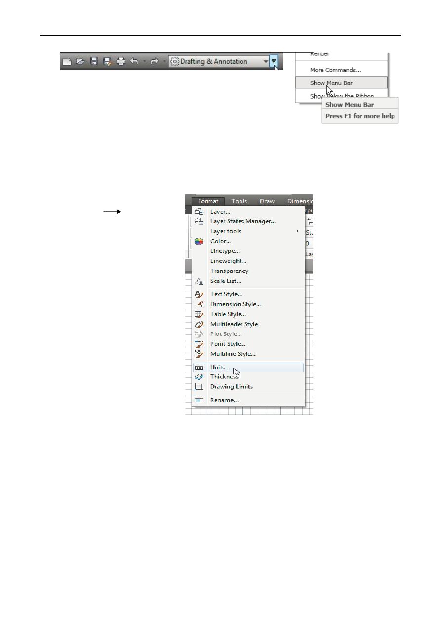
2. If necessary, click on the down-arrow in the Quick Access bar and select Show Menu Bar to
display the AutoCAD Menu Bar. The Menu Bar provides access to all AutoCAD commands.
Lecture 2 Yazen H Shakir & Mohanad AL-Rekany
2
Drawing Units Setup:
Every object we construct in a CAD system is measured in units. We should determine the
system of units within the CAD system before creating the first geometric entities.
1. In the Menu Bar select:
[Format] [Units]
The AutoCAD Menu Bar contains multiple pull-down menus where all of the AutoCAD
commands can be accessed. Note that many of the menu items listed in the pull-down menus
can also be accessed through the Quick Access toolbar and/or Ribbon panels.
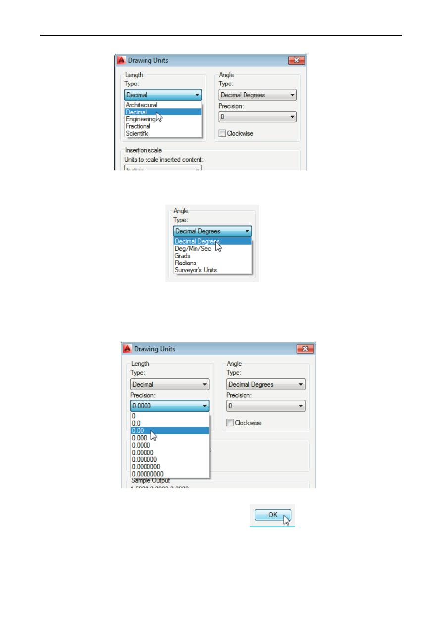
2. Click on the Length Type option to display the different types of length units available. Confirm
the Length Type is set to Decimal.
Lecture 2 Yazen H Shakir & Mohanad AL-Rekany
3
3. On your own, examine the other settings that are available.
4. In the Drawing Units dialog box, set the Length Type to Decimal. This will set the
measurement to the default English units, inches.
5. Set the Precision to two digits after the decimal point as shown in the above figure.
6. Pick OK to exit the Drawing Units dialog box.
Lecture 2 Yazen H Shakir & Mohanad AL-Rekany
4
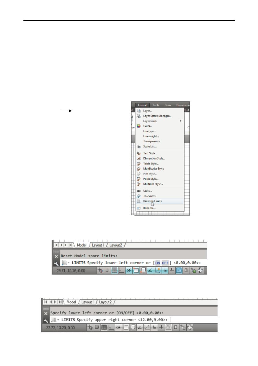
Drawing Area Setup:
We will set up the Drawing Limits by entering a command in the command prompt area.
Setting the Drawing Limits controls the extents of the display of the grid. It also serves as a
visual reference that marks the working area. It can also be used to prevent construction outside
the grid limits and as a plot option that defines an area to be plotted/printed. Note that this
setting does not limit the region for geometry construction.
1. In the Menu Bar select:
[Format] [Drawing Limits]
2. In the command prompt area, the message “Reset Model Space Limits: Specify lower left
corner or [On/Off] <0.00,0.00>:” is displayed. Press the ENTER key once to accept the
default coordinates <0.00,0.00>.
3. In the command prompt area, the message “Specify upper right corner <12.00,9.00>:” is
displayed. Press the ENTER key again to accept the default coordinates <12.00,9.00>.
Lecture 2 Yazen H Shakir & Mohanad AL-Rekany
5
4. On your own, move the graphics cursor near the upper-right corner inside the drawing area
and note that the drawing area is unchanged. (The Drawing Limits command is used to set the
drawing area, but the display will not be adjusted until a display command is used).
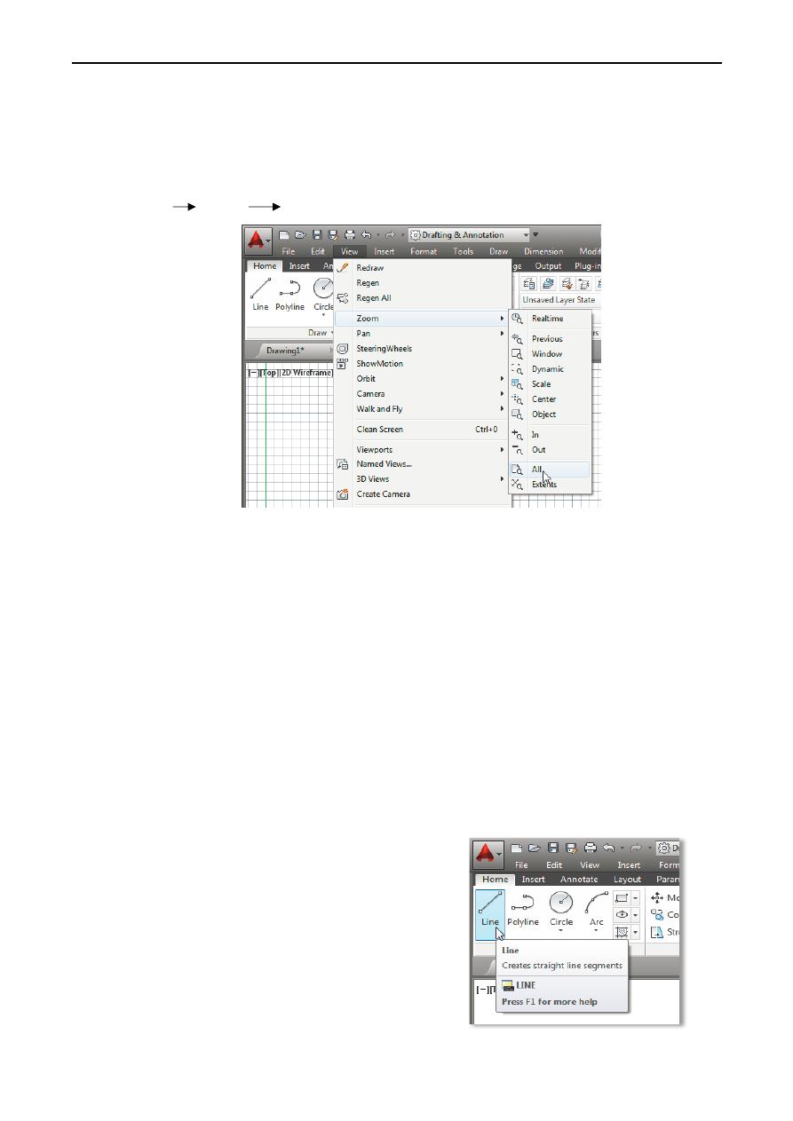
5. Inside the Menu Bar area select:
[View] [Zoom] [All]
The Zoom All command will adjust the display so that all objects in the drawing are displayed
to be as large as possible. If no objects are constructed, the Drawing Limits are used to adjust
the current viewport.
6. Move the graphics cursor near the upper-right corner inside the drawing area and note that the
display area is updated.
7. Hit the function key [F7] once to turn off the display of the Grid lines.
Note that function key [F7] is a quick key, which can be used to quickly toggle n/off the grid
display. Also, note the command prompt area can be positioned to dock below the drawing
area or float inside the drawing area as shown.
Drawing Lines with the LINE Command:
1. Move the graphics cursor to the first icon in the Draw
panel. This icon is the Line icon. Note that a brief
description of the Line command appears next to the
cursor.
2. Select the icon by clicking once with the left mouse-
button, which will activate the Line command.
Lecture 2 Yazen H Shakir & Mohanad AL-Rekany
6
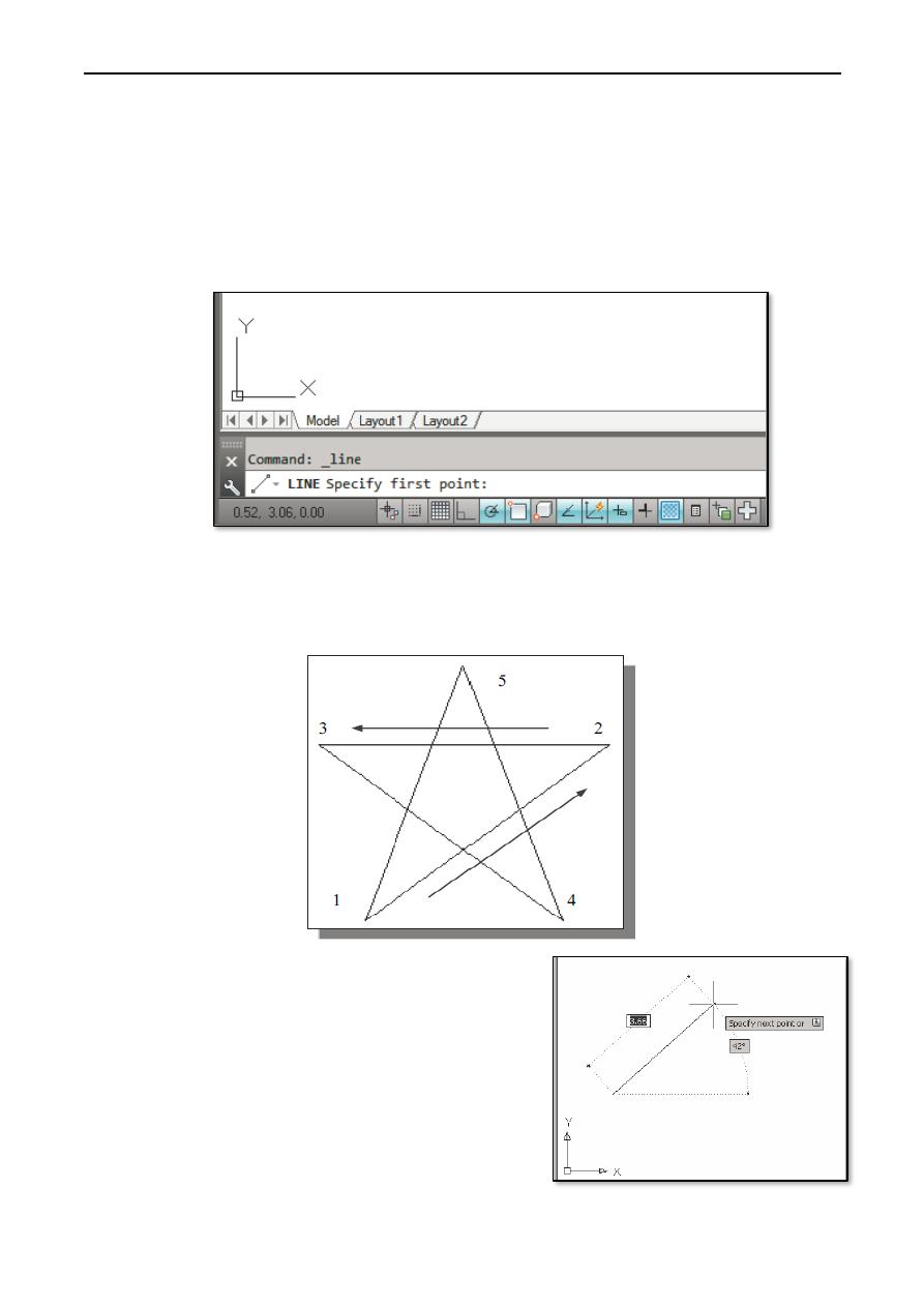
3. In the command prompt area, near the bottom of the AutoCAD drawing screen, the message
“_line Specify first point:” is displayed. AutoCAD expects us to identify the starting location
of a straight line. Move the graphics cursor inside the graphics window and watch the display
of the coordinates of the graphics cursor at the bottom of the AutoCAD drawing screen. The
three numbers represent the location of the cursor in the X, Y, and Z directions. We can treat
the graphics window as if it was a piece of paper and we are using the graphics cursor as if it
were a pencil with which to draw.
We will create a freehand sketch of a five-point star using the Line command. Do not be
overly concerned with the actual size or accuracy of your freehand sketch. This exercise is
to give you a feel for the AutoCAD ®2014 user interface.
4. We will start at a location about one-third from the
bottom of the graphics window. Left-click once to
position the starting point of our first line. This will
be point 1 of our sketch. Next move the cursor
upward and toward the right side of point 1. Notice
the rubber-band line that follows the graphics cursor
in the graphics window. Left-click again (point 2)
and we have created the first line of our sketch.
Lecture 2 Yazen H Shakir & Mohanad AL-Rekany
7
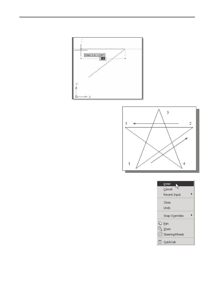
5. Move the cursor to the left of point 2 and create a horizontal line about the same length as the
first line on the screen.
6. Repeat the above steps and complete the freehand
sketch by adding three more lines (from point 3 to
point 4, point 4 to point 5, and then connect to point
5 back to point 1).
7. Notice that the Line command remains activated
even after we connected the last segment of the line
to the starting point (point 1) of our sketch. Inside
the graphics window, click once with the right-
mouse-button and a popup menu appears on the
screen.
8. Select Enter with the left-mouse-button to end the Line command.
(This is equivalent to hitting the [ENTER] key on the keyboard).
9. Move the cursor near point 2 and point 3, and estimate the length of
the horizontal line by watching the displayed coordinates for each
point.
Lecture 2 Yazen H Shakir & Mohanad AL-Rekany
8
Circle drawing methods:
To create circles, you can specify various combinations of
center, radius, diameter, points on the circumference, and
points on other objects.
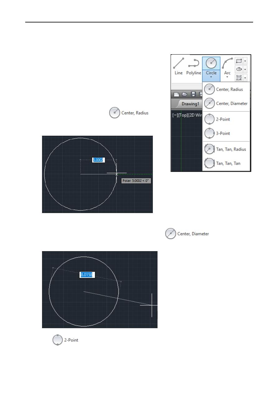
We can create circles in several ways. The default method is to
specify the center and the radius. Three other ways to draw a
circle are shown in the figure:
1. Draws a circle based on a
center point and a radius.
Defines the radius of the circle. Enter a value, or specify
a point, for example:
2. Draws a circle based on a center point and a diameter.
Defines the diameter of the circle. Enter a value, or
specify a second point, for example:
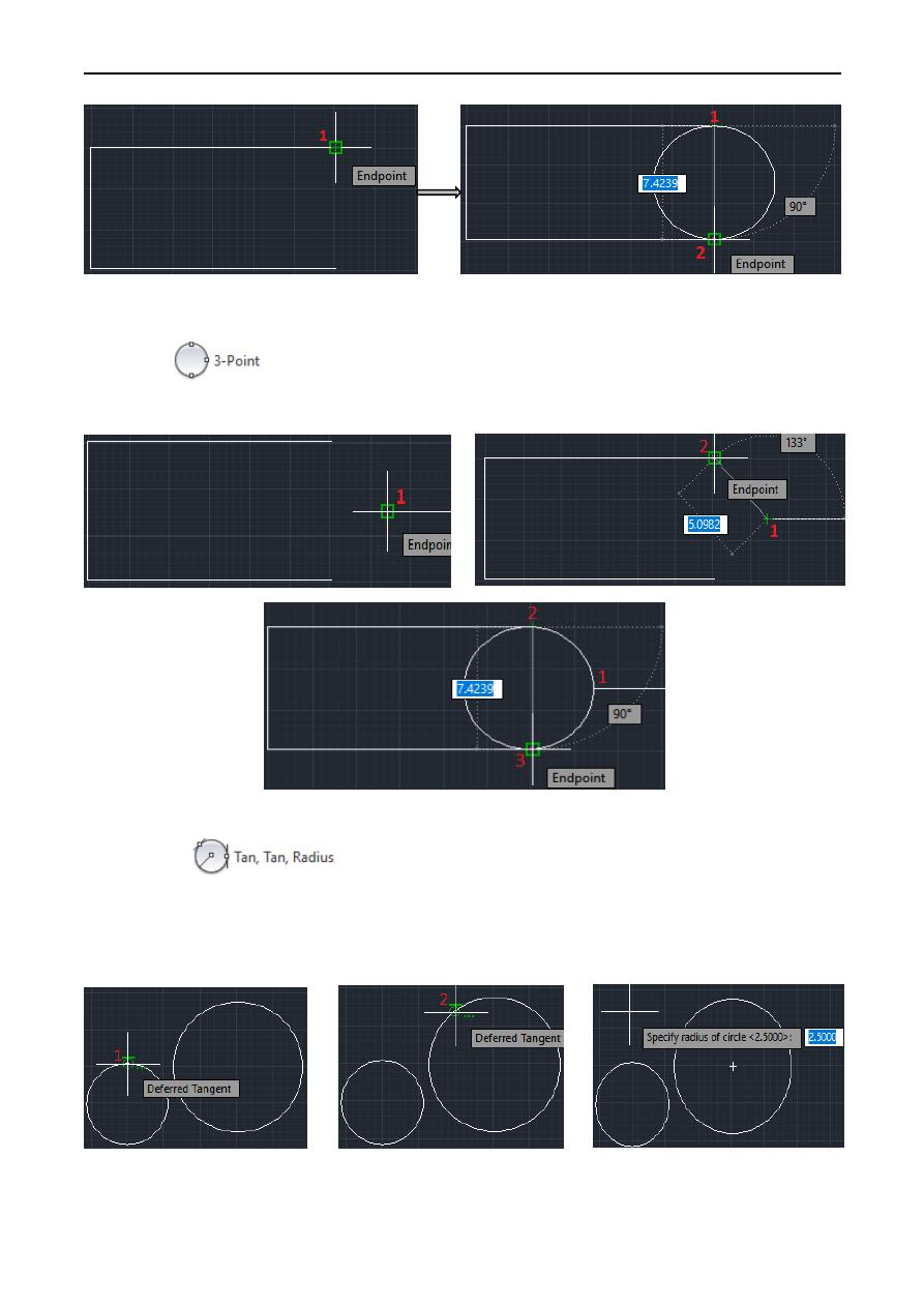
3. 2P
Draws a circle based on two endpoints of the diameter, for example:
Lecture 2 Yazen H Shakir & Mohanad AL-Rekany
9
4. 3P
Draws a circle based on three points on the circumference, for example:
5. TTR
Draws a circle with a specified radius tangent to two objects. Sometimes more than one circle
matches the specified criteria. The program draws the circle of the specified radius whose
tangent points are closest to the selected points, for example:
Lecture 2 Yazen H Shakir & Mohanad AL-Rekany
10
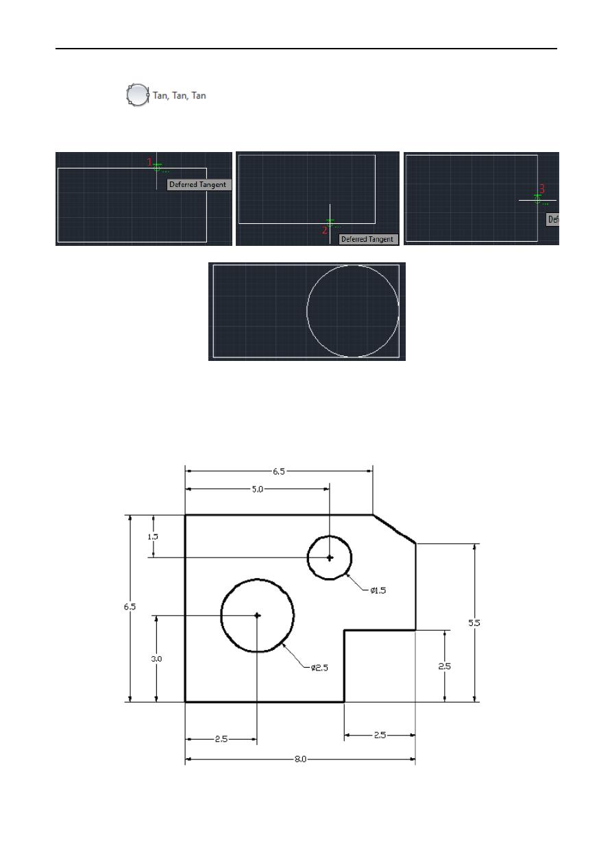
6. TTT
Creates a circle tangent to three objects, for example:
Practicing simple exercise:
We will next create a mechanical design using the different coordinate entry methods.
Lecture 2 Yazen H Shakir & Mohanad AL-Rekany
11
The rule for creating CAD designs and drawings is that they should be created at full size using
real-world units. The CAD database contains all the definitions of the geometric entities and the
design is considered as a virtual, full-sized object. Only when a printer or plotter transfers the CAD
design to paper is the design scaled to fit on a sheet. The tedious task of determining a scale factor
so that the design will fit on a sheet of paper is taken care of by the CAD system.
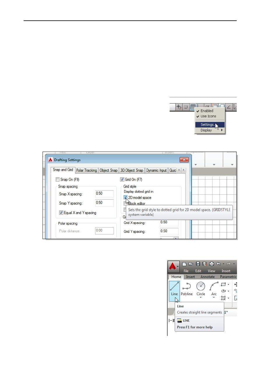
GRID Style Setup
1. In the Status Bar area, right-mouse-click on Snap Mode
and choose [Snap settings].
2. In the Drafting Settings dialog box, select the Snap and
Grid tab if it is not the page on top.
3. Change Grid Style to Display dotted grid in 2D model
Space as shown in the below figure.
4. Pick OK to exit the Drafting Settings dialog box.
Line command
1. Select the Line command icon in the Draw toolbar. In the
command prompt area, near the bottom of the AutoCAD
graphics window, the message “_line Specify first point:” is
displayed. AutoCAD expects us to identify the starting
location of a straight line.
2. We will locate the starting point of our design at the origin
of the world coordinate system. Command: _line Specify
first point: 0,0 (Type 0,0 and press the [ENTER] key once.)
Lecture 2 Yazen H Shakir & Mohanad AL-Rekany
12
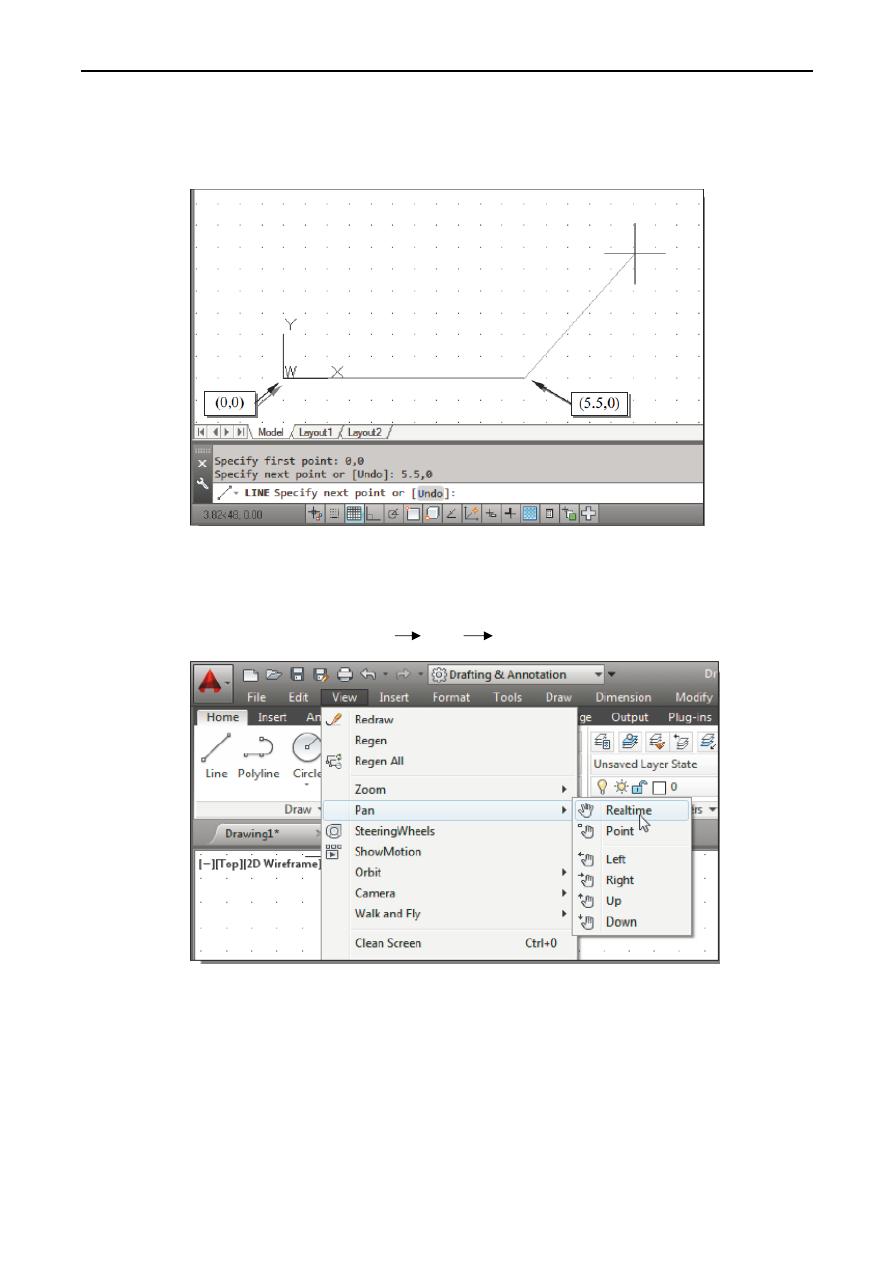
3. We will create a horizontal line by entering the absolute coordinates of the second point.
Specify next point or [Undo]: 5.5,0 [ENTER].
Note that the line we created is aligned to the bottom edge of the drawing window. Let us adjust
the view of the line by using the Pan Realtime command.
4. In the Menu Bar area select: [View] [Pan] [Realtime]
The available Pan commands enable us to move the view to a different position. The
Pan-Realtime function acts as if you are using a video camera.
5. Move the cursor, which appears as a hand inside the graphics window, near the center of the
drawing window, then push down the left-mouse-button and drag the display toward the right
and top side until we can see the sketched line. (Notice the scroll bars can also be used to adjust
viewing of the display.)
Lecture 2 Yazen H Shakir & Mohanad AL-Rekany
13
6. Press the [Esc] key to exit the Pan-Realtime command. Notice that AutoCAD goes back to the
Line command.
7. We will create a vertical line by using the relative rectangular coordinates entry method,
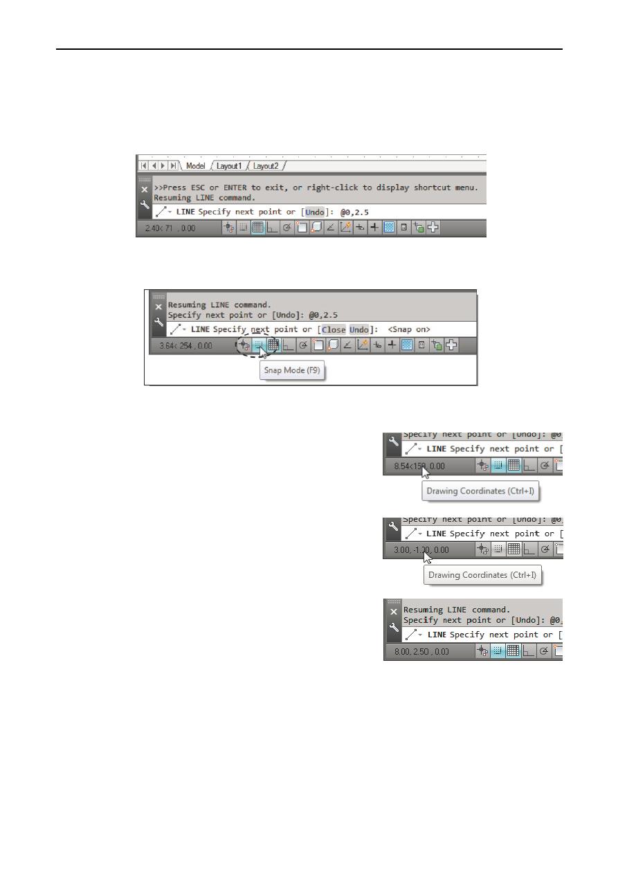
relative to the last point we specified: Specify next point or [Close/Undo]: @0,2.5 [ENTER]
8. We can mix any of the entry methods in positioning the locations of the endpoints. Move the
cursor to the Status Bar area, and turn ON the SNAP MODE option.
Note that the Line command is resumed as the settings are adjusted.
9. Left-click once on the coordinates display area to
switch to a different coordinate display option. Note the
coordinates display area has changed to show the length
of the new line and its angle. Each click will change the
display format of the cursor coordinates.
10. On your own, left-click on the coordinates display area
to observe the switching of the coordinate display; set
the display back to using the world coordinate system.
11. Create the next line by picking the location, world
coordinates (8,2.5), on the screen.
12. We will next use the relative polar coordinates entry method, relative to the last point we
specified: Specify next point or [Close/Undo]: @3<90 [ENTER] (Distance is 3 inches with an
angle of 90 degrees.)
Lecture 2 Yazen H Shakir & Mohanad AL-Rekany
14
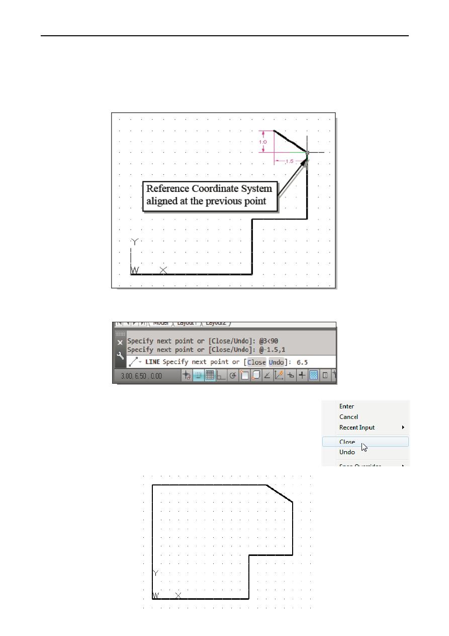
13. Using the relative rectangular coordinates entry method to create the next line, we can imagine
a reference coordinate system aligned at the previous point. Coordinates are measured along
the two reference axes. Specify next point or [Close/Undo]: @-1.5,1 [ENTER] (-1.5 and 1
inches are measured relative to the reference point.)
14. Move the cursor directly to the left of the last point and use the direct distance entry technique
by entering 6.5 [ENTER].
15. For the last segment of the sketch, we can use the Close option to
connect back to the starting point. Inside the graphics window, right-
mouse-click and a popup menu appears on the screen.
16. Select Close with the left-mouse-button to connect back to the
starting point and end the Line command.
Lecture 2 Yazen H Shakir & Mohanad AL-Rekany
15
Circles command
The menus and toolbars in AutoCAD® 2014 are designed to allow the CAD operator to quickly
activate the desired commands.
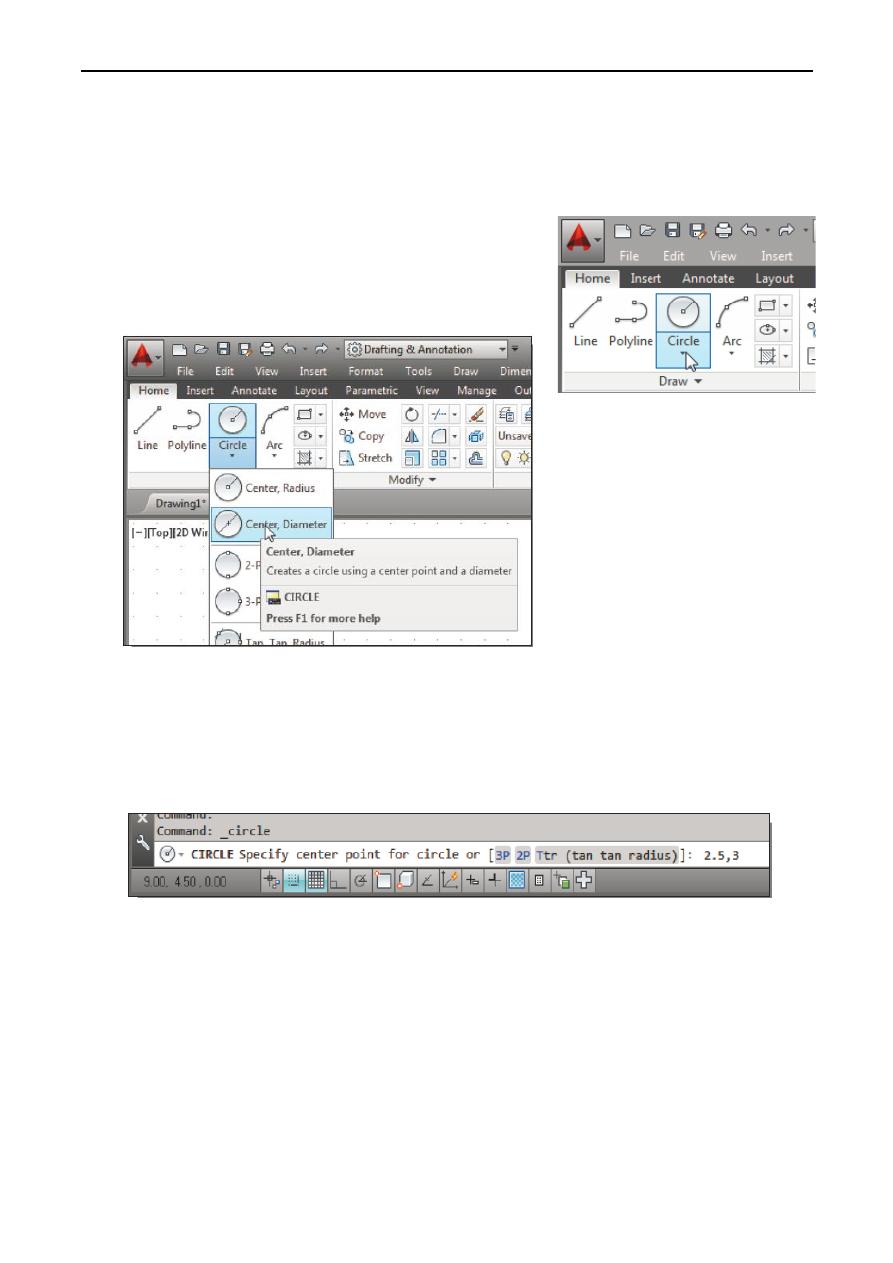
1. In the Draw toolbar, click on the little triangle below the
circle icon. Note that the little triangle indicates
additional options are available.
2. In the option list, select: [Center, Diameter]
3. In the command prompt area, the message “Specify center point for circle or [3P/2P/Ttr (tan
tan radius)]:” is displayed. AutoCAD expects us to identify the location of a point or enter an
option. We can use any of the four coordinate entry methods to identify the desired location.
We will enter the world coordinates (2.5,3) as the center point for the first circle.
Specify center point for circle or [3P/2P/Ttr (tan tan radius)]: 2.5,3 [ENTER]
4. In the command prompt area, the message “Specify diameter of circle:” is displayed.
Specify diameter of circle: 2.5 [ENTER]
Lecture 2 Yazen H Shakir & Mohanad AL-Rekany
16
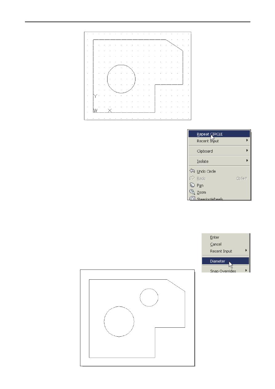
5. Inside the graphics window, right-mouse-click to bring up the
popup option menu and Pick Repeat CIRCLE with the left-
mouse-button in the popup menu to repeat the last command.
6. Using the relative rectangular coordinates entry method,
relative to the center-point coordinates of the first circle, we
specify the location as (2.5,2).
Specify center point for circle or [3P/2P/Ttr (tan tan radius)]:
@2.5,2 [ENTER]
7. In the command prompt area, the message “Specify Radius of circle: <2.50>” is displayed. The
default option for the Circle command in AutoCAD is to specify the radius and the last radius
used is also displayed in brackets.
8. Inside the graphics window, right-mouse-click to bring up the popup
option menu and select Diameter as shown.
9. In the command prompt area, enter 1.5 as the diameter.
Specify Diameter of circle<2.50>: 1.5 [ENTER]
Lecture 2 Yazen H Shakir & Mohanad AL-Rekany
17
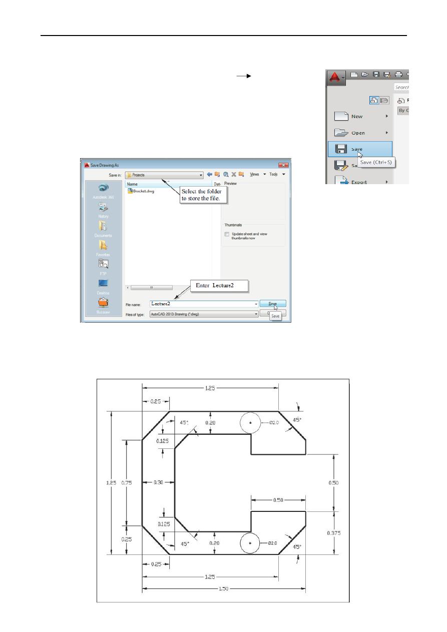
Saving the CAD Design
1. In the Application Menu, select: [Application] [Save]
Note the command can also be activated with quick key
combination of [Ctrl]+[S].
2. In the Save Drawing as dialog box, select the folder in which you want
to store the CAD file and enter Lecture2 in the File name box.
3. Click Save in the Save Drawing as dialog box to accept the selections and save the file. Note
the default file type is DWG, which is the standard AutoCAD drawing format.
Homework: