Lecture 3 Yazen H Shakir & Mohanned AL-Rekany
1
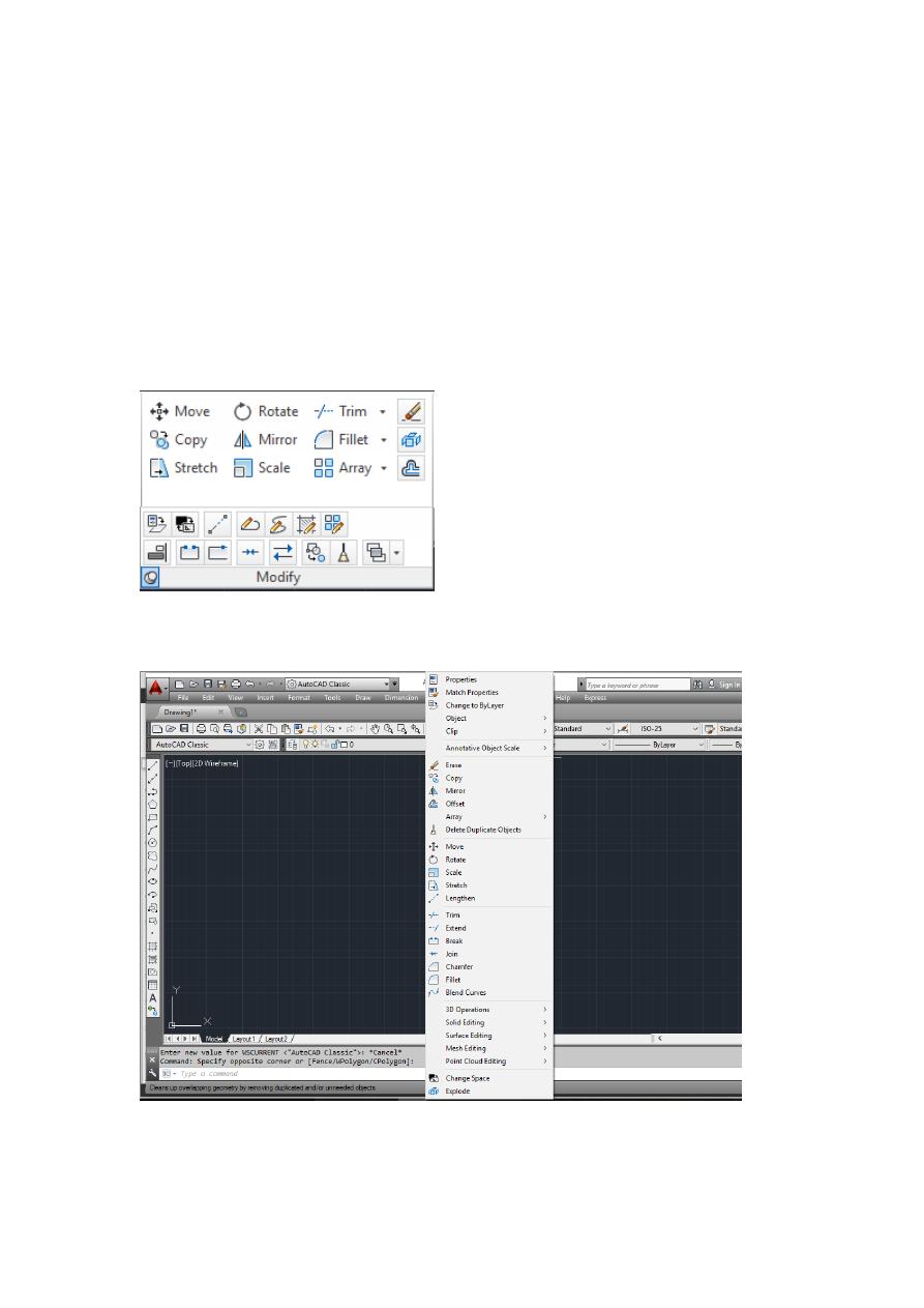
Modify Toolbox
In the previous lectures we have learnt how to use the basics drawing tools (Line,
Circle) to draw simple shapes. Today we are going to focus a bit on the tools that
assists AutoCAD users to edit a sketch to modify length or appearances for instance.
AutoCAD eases the process much compared with Manual approach through modify
tool box features such as copy, rotate and mirror…etc.
1. Access to Modify Toolbox:
1- Directly from Annotation & Drafting panel
2- Go to menu bar after converting the view to AutoCAD classic then [Modify] as
shown :
Lecture 3 Yazen H Shakir & Mohanned AL-Rekany
2
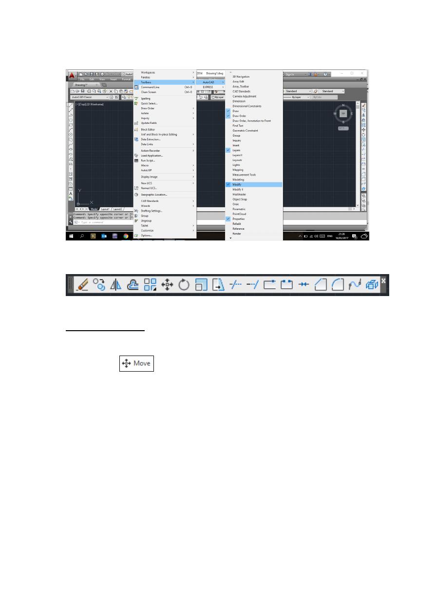
3- Go to [Tools]-----[Toolbars]-----[AutoCAD]-----[Modify] as below:
So the modify toolbox will appear to the left side hand of the workspace we can drag
and drop it in any place of the drawing area.
2. Modify commands:
2.1 Move Command:
1- Choose Modify, Move.
Or
2- Click
Or
3. Type MOVE at the command prompt Command: MOVE or M
4. Pick Objects to move Select objects: (select)
5. Pick a point to move from Base point or displacement: (pick point)
6. Pick a point to move to Second point of displacement: (pick point)
TIP:
To move an object a specified distance, type a distance at the second point of
displacement prompt: @1<0
Lecture 3 Yazen H Shakir & Mohanned AL-Rekany
3
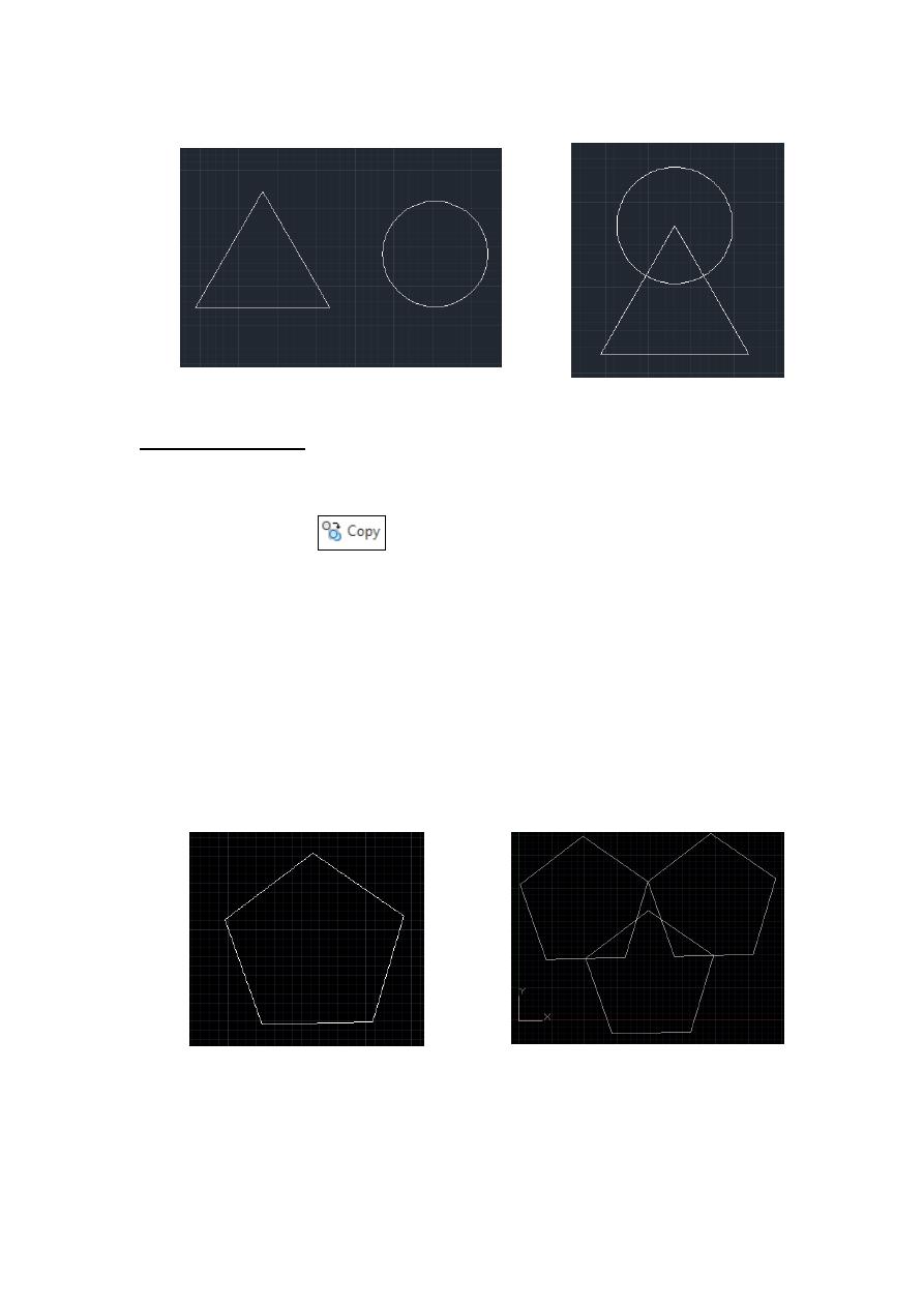
Circle before move
Circle after move
2.2 Copy Command:
1. Choose Modify, Copy.
Or
2. Click the Copy icon.
Or
3. Type COPY at the command prompt. Command: COPY or CP
4. Pick Objects to copy. Select objects: (select)
5. Pick a point to move from. Base point or displacement/Multiple: (pick point).
6. Pick a point to copy to. Second point of displacement: (pick point) Or
7. Type a point to copy to. Second point of displacement: @ 1<0
Tip:
you can use [Ctrl +C] for copy and [Ctrl +V] for pasting .in addition you can use [Shift
+Ctrl+C] to specify the base point before even drop the copied object in the second point
coordinate.
Pentagon before applying Copy multiple copies after applying Copy
Lecture 3 Yazen H Shakir & Mohanned AL-Rekany
4
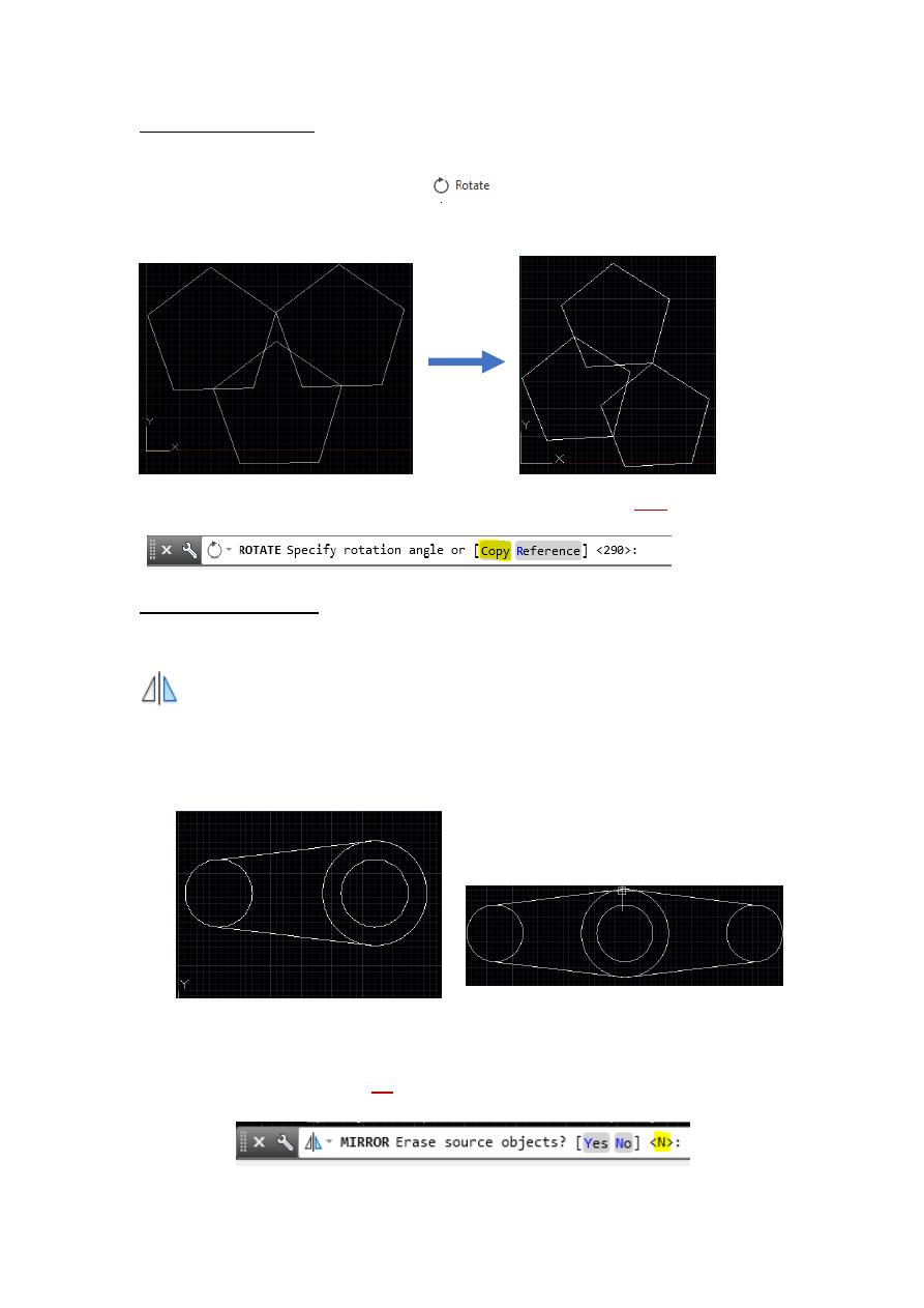
2.3 Rotate Command:
This command allows you to rotate an object around a base point. We can activate this
command by either pressing this button
or by type rotate OR ro. The following
example is a bout rotating an object by 290 degrees:
Note: one of the options or rotate command is not only rotation but also copy included as well
2.3 Mirror Command:
Creates a mirrored copy of selected objects.
You can create objects that represent half of a drawing, select them, and mirror them across a
specified line to create the other half.
Object need to be symmetric
after using mirror command
Tip: when the command mirror is done AutoCAD ask you to keep the original source or
erased it, by default the answer No is activated
Lecture 3 Yazen H Shakir & Mohanned AL-Rekany
5
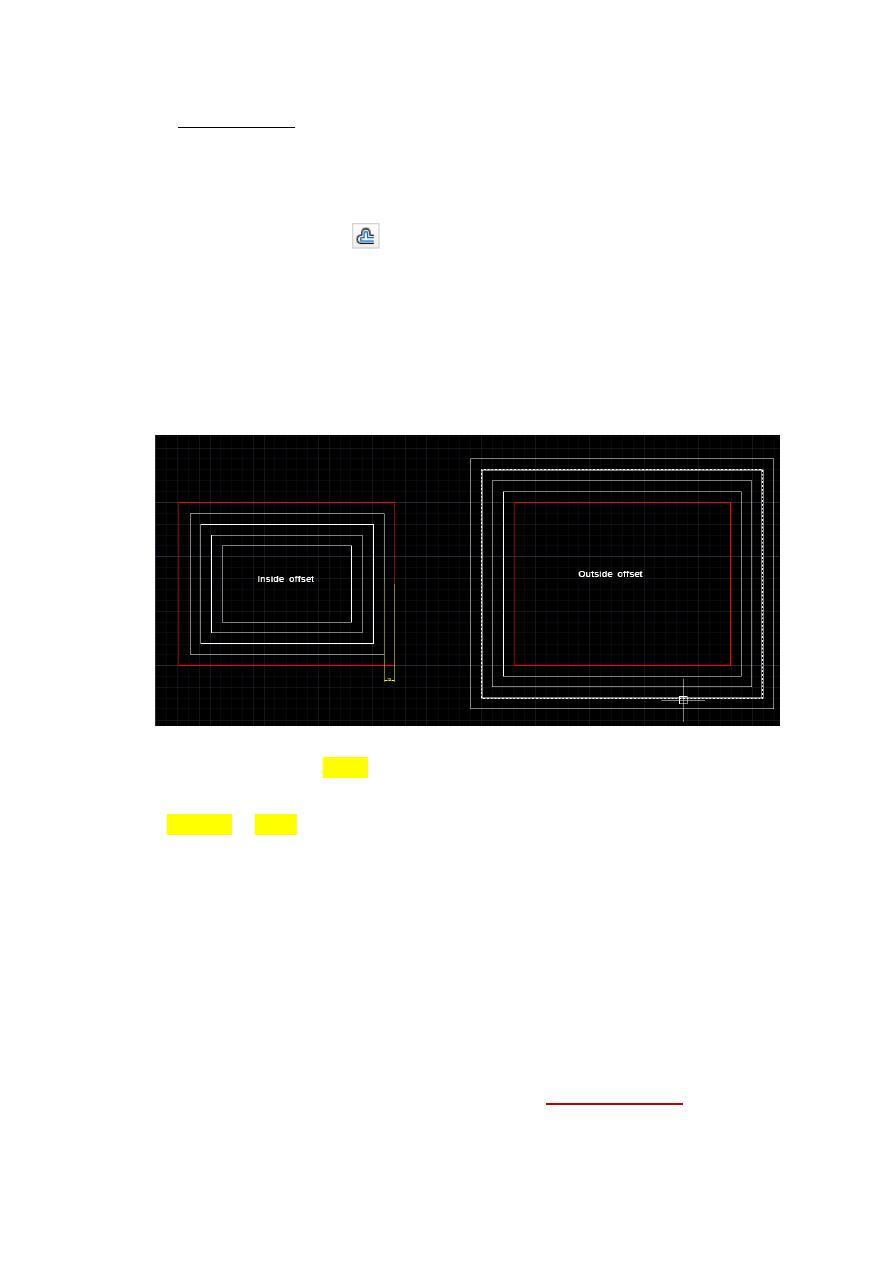
2.4 Offset Distance
To offset a specified distance:
1. Choose Modify, Offset.
Or
2. Choose the Offset icon.
Or
3. Type OFFSET at the command prompt. Command: OFFSET or O
4. Type the distance to offset. Offset distance or <Through point>: (number)
5. Pick the object to offset. Select object to offset: (select object)
6. Pick A side to offset object to. Side to offset: (pick side)
The main purpose behind Offset an object is to create a new object whose shape is
parallel to the original object.
Use OFFSET to offset the following object types:
Lines
Arcs
Circles
Ellipses and elliptical arcs (resulting in an oval-shaped spline)
2D polylines
Construction lines (xlines) and rays
Splines
Tip
An effective drawing technique is to use offset objects and then trim or extend their ends
to achieve accurate measurements.
Lecture 3 Yazen H Shakir & Mohanned AL-Rekany
6
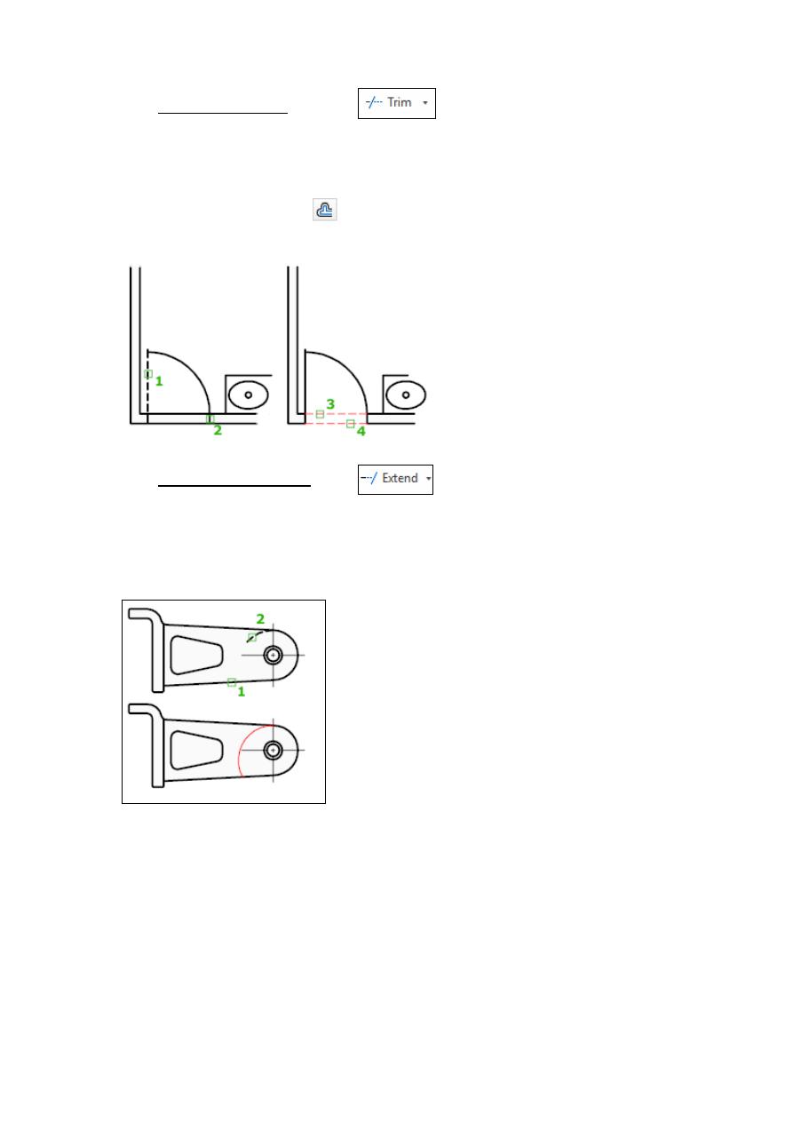
2.5 TRIM (Command)
Trim process such as a scissor to cut the additional edges. In other words trims objects to
meet the edges of other objects.
To trim objects, select the boundaries. Then press Enter and select the objects that you want
to trim. To use all objects as boundaries, press Enter at the first Select Objects prompt.
2.6 EXTEND (Command)
Extends objects to meet the edges of other objects. To extend objects, first select the
boundaries. Then press Enter and select the objects that you want to extend. To use all objects
as boundaries, press Enter at the first Select Objects prompt.
Both of trim and extend commands have a list of promote:
1. Fence:
Selects all objects that cross the selection fence. The selection fence is a series of
temporary line segments that you specify with two or more fence points. The selection fence
does not form a closed loop.
2.
Crossing:
Selects objects within and crossing a rectangular area defined by two
points.
Note
some crossing selections of objects to be extended are
ambiguous. EXTEND or TRIM resolves the selection by following along the
rectangular crossing window in a clockwise direction from the first point to the first
object encountered.
Lecture 3 Yazen H Shakir & Mohanned AL-Rekany
7
3. Project: Specifies the projection method used when trimming or extending objects.
4. Edge: Determines whether an object is trimmed or extended at another object's
extrapolated edge or only to an object that intersects it in 3D space.
5. Erase: Deletes selected objects. This option provides a convenient method to erase
unneeded objects without leaving the TRIM or EXTEND commands.
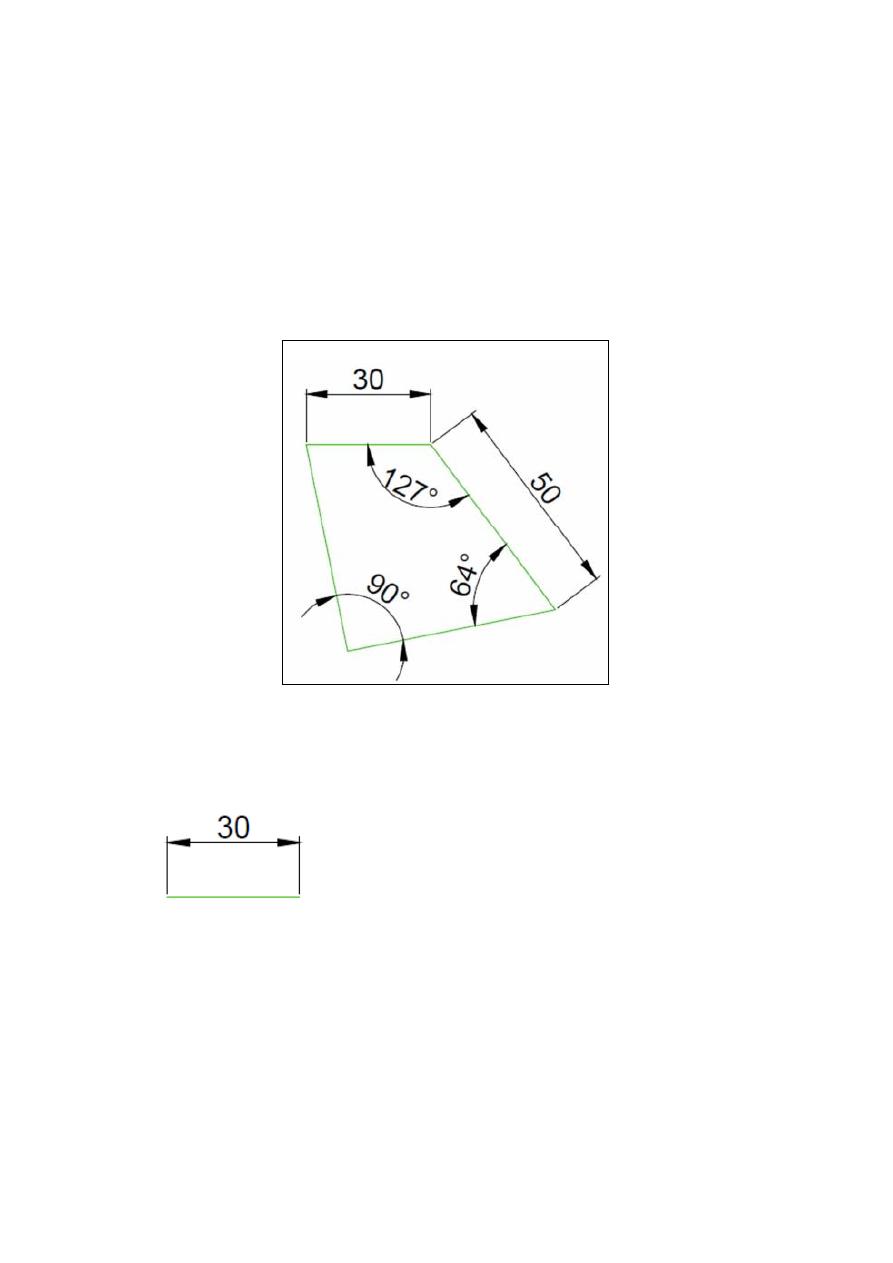
Exercises:
Solution for Previous Example:
Step 1
Draw the following line
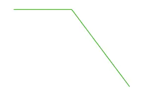
Step 2
Draw the second line starting from the right end of the previously drawn
line. Use @50<-53 to draw it, and you should have the following.

Lecture 3 Yazen H Shakir & Mohanned AL-Rekany
8
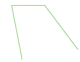
Step 3
Draw a line starting on the left end of the 30 unit line using @50<-79 (
50
of length is arbitrary chosen and the angle 79 is found by doing 360-90-64-127
– the Sum of angles in any Quadrilateral is 360 degrees
).
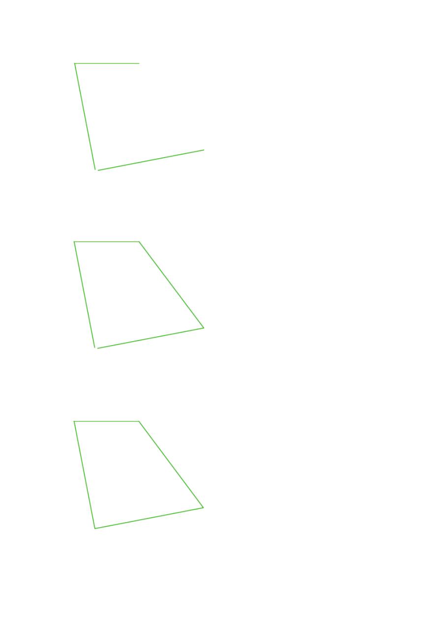
Step 4
Draw a line of an arbitrary chosen length but make sure it forms 64
degrees with the line we have created in Step 2
(
You can do this by creating a line aligned with the line with created in Step 2
and rotating it with 64 degrees counter clockwise
)
What I will do here is:
Rotate the line created in step 2 from it bottom end with 64 degrees
counter clockwise.
Lecture 3 Yazen H Shakir & Mohanned AL-Rekany
9
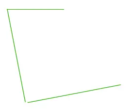
Step 5
Create a line on the open side of the quadrilateral from the 2 points
such as having the following.
Step 6
Use the Fillet command with R=0 to join those two lines to close that
hole at the bottom of the figure