
Combinational Logic Circuits
The digital system consists of two types of circuits
I.
Combinational circuits
II.
Sequential circuits
A combinational circuit consists of logic gates whose outputs at any time are
determined from only the present combination of inputs without regard to previous
inputs or previous state of outputs.
In sequential circuits, the outputs of the circuit depend not only on present values of
inputs, but also on past inputs and outputs states. Thus, they require storage
elements in addition to logic gates.
A combinational circuit consists of input variables, logic gates and output variables.
Any combinational circuit can be designed by the following steps:
1. Problem statement.
2. Identify the input variables and output function.
3. The input and output variables are assigned letter symbols.
4. Complete the truth table that defines the relationship between the input variables
and output functions.
5. The simplified Boolean expression is obtained by Boolean algebraic method or
Karnaugh map method.
6. A Circuit diagram is implemented from the simplified expression using logic gates.
Design of Half Adders
A combinational circuit that performs the addition of two bits is called a half-adder.
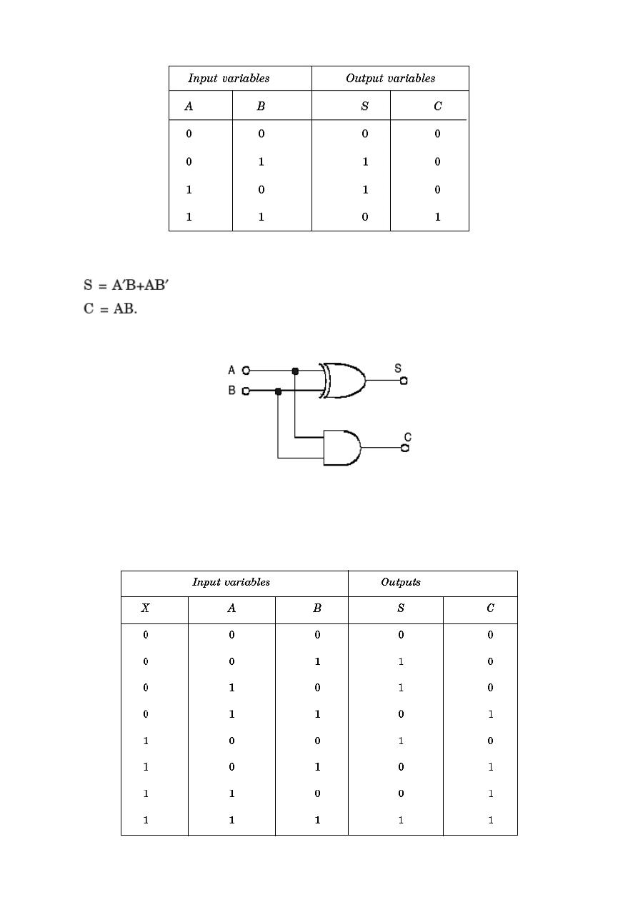
From the truth table above, the outputs S and C functions can be obtained as:
The logic diagram to implement the half-adder circuit is:
Full Adders
A combinational circuit of full-adder performs the operation of addition of three bits
the augend A
(ا
لمضاف االها, addend B فاضملا( and previous carry X to produce the
outputs sum S and carry C.
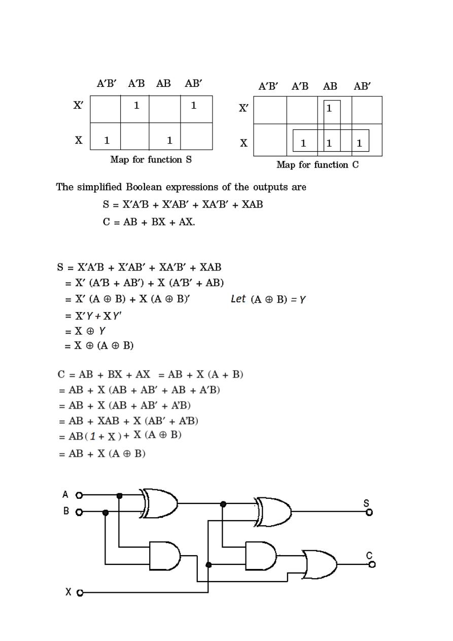
To derive the simplified Boolean expression from the truth table, the Karnaugh map
method is used
The Boolean expressions of S and C are modified as follow:
The logic diagram according to the modified expression is
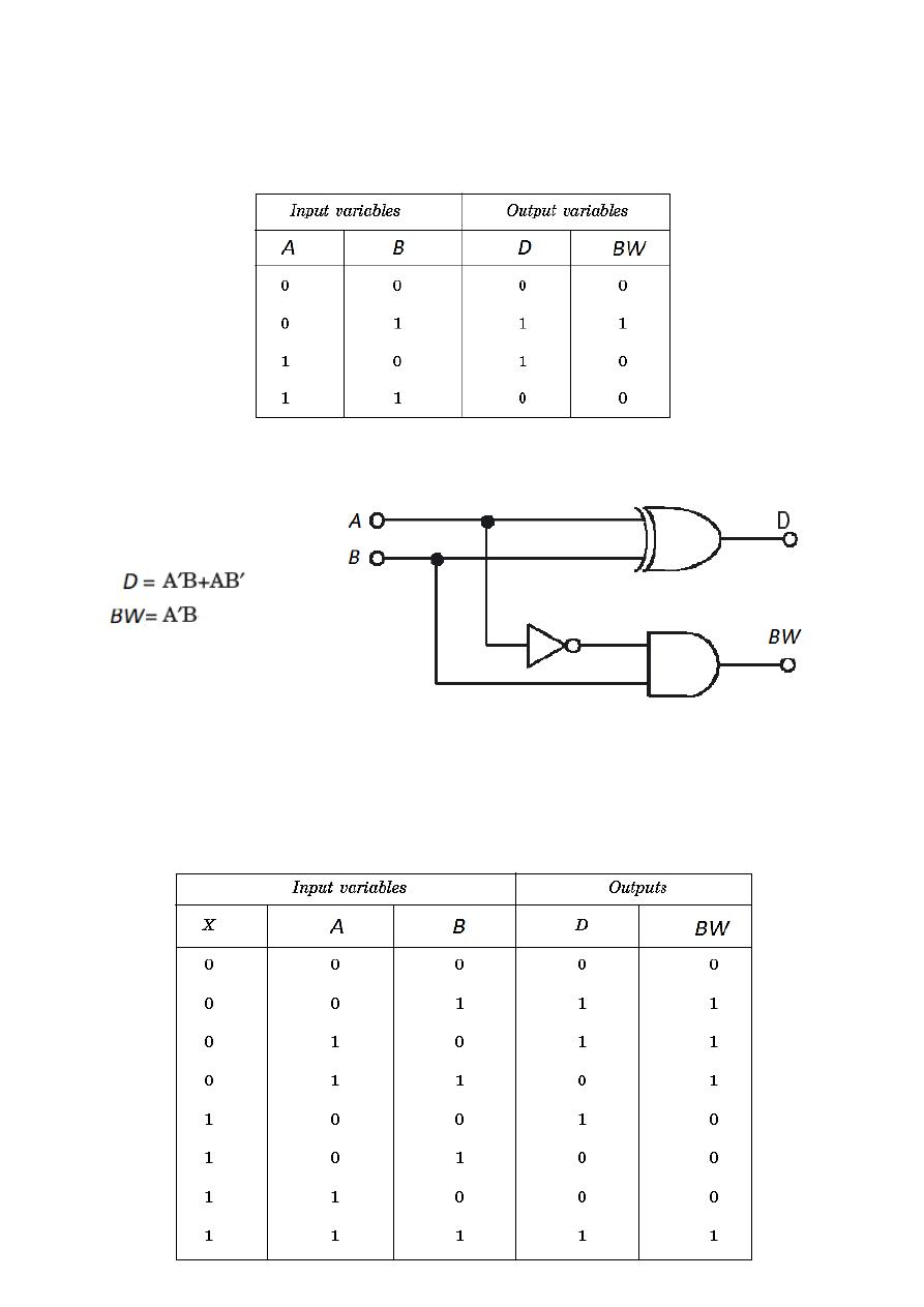
Half Subtractor
A combinational circuit that performs the subtraction of two bits as described above is
called a half-Subtractor.
By considering the minterms of the truth table, the Boolean expressions of the
outputs Difference (D) and borrow (BW) functions can be written as
Full Subtractor
A combinational circuit of full Subtractor performs the operation of subtraction of
three bits the minuend (A), subtrahend (B) and borrow (X) which is generated from
the subtraction operation of previous digits and produces the outputs difference &
borrow.
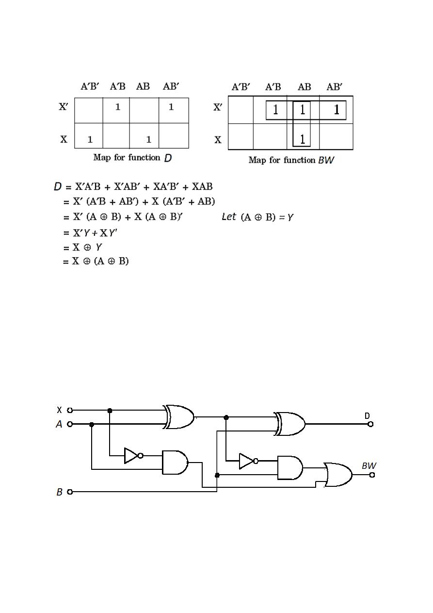
Karnaugh maps are prepared to derive simplified Boolean expressions of D and BW
(
)
(
)
(
)
(
)
(
)
( )