background image


(1)  

xperiment 

E

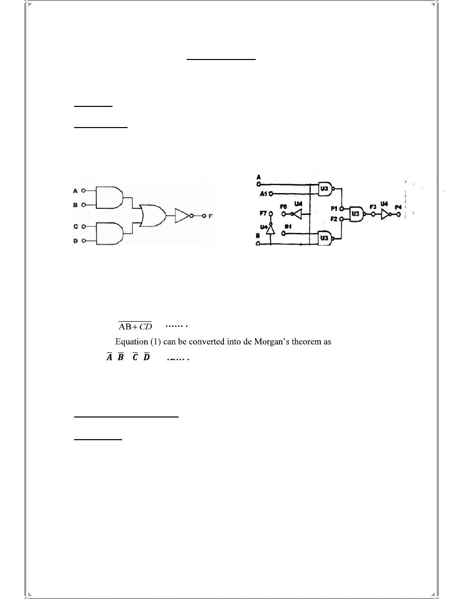
AND-OR-INVERTER (A-O-I) Gate  Circuit


bjective

O


Understanding the basic principles of combined logic.


ntroduction:

I        

AND-OR-INVERTER (A-O-I)

 gates consist of two AND gates,  


one


OR


gate


Inverter


(NOT)


Gate.


and


one


The Boolean expression for the output F4 is:


)

Equation (1


 =  


:

        F=( + ).( + )

 Equation (2)

                  Equation (1) is also referred to as (Sum of Products)
                  Equation (2) is also referred to as (Product of Sum)


c )


block


(

33002

-

Digital Logic Lab; Module KL


:

quipments Required

E


:

rocedures

P


1. Connect inputs (A, A

1

, B, B

1

) to Data Switches SWo, SW

1

, SW

2

, SW

3

 respectively 

and connect outputs F

3

, F

4

 to logic indicators L

1

, L

2

 . 

2. Set B and B1 to '0', follow the input sequences for A and Al in Table (3-1) and


record the output.  


=

3. What does F3 act Between A & A1?


4. Set


A


=


A1


=


0,


follow


the


input


sequences


for


B


&


B1


in


Table (3-2)  

and  

record  

the  


   output.


 What does F3 act Between B & B1?


background image


1

gate between B and B


D

act as an AN


3

, Does F

'

0

'


1

A

and 


When A


5.


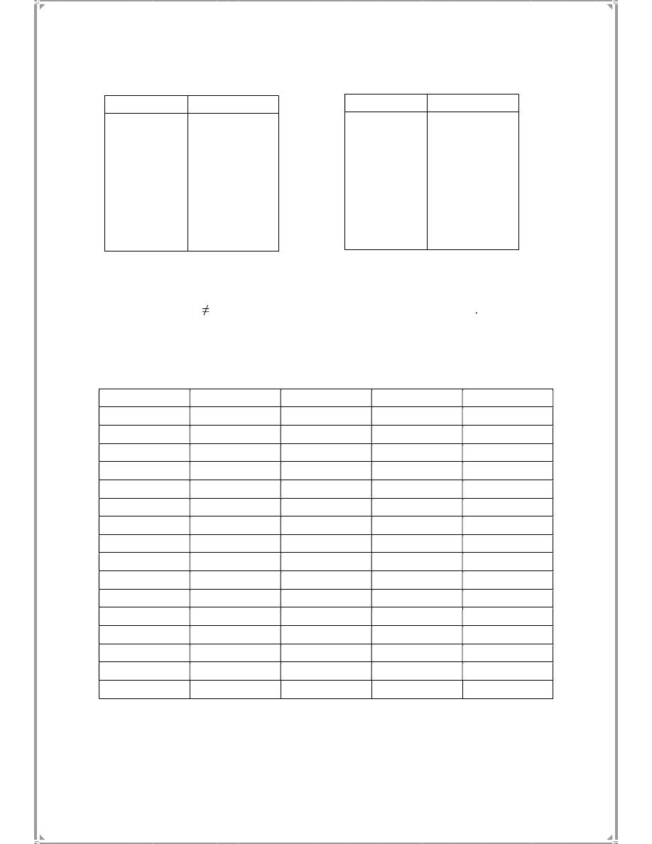
 6. Follow the following table and record the output? 


equal 


to


A.A1 + B.B1


3


F

Prove  that  


F3

B1


B

A1

A

0

0

0

0

1

0

0

0

0

1

0

0

1

1

0

0

0

0

1

0

1

0

1

0

0

1

1

0

1

1

1

0

0

0

0

1

1

0

0

1

0

1

0

1

1

1

0

1

0

0

1

1

1

0

1

1

0

1

1

1

1

1

1

1


F3         F4


A1         A

0          0


0          1


1          0


1          1


F3         F4


B1         B

0          0


0          1


1          0


1          1


Table(3-1)


Table(3-2)

Table(3-3)

7. If B= A' and B1= A1' , What do the output functions


(F3


&


F4) represent?

Why?


background image


Discussion:

    1.What logic does the  A-O-I circuit represent?                                                                                                                                                                      

                          a. AND                           b. NAND                                c.

  Both


. What is the output of an A-O-I gate? 


                          a. 

                     b. (A+B).(C+D)                      c. ABCD

.  

expressed as:


                           a. AB + CD                       

b.  

(A+B).(C+D)                   c .ABCD 


4. What are the advantages of using AOI?


رفعت المحاضرة من قبل: Mohammed Aldhanuna
المشاهدات: لقد قام 0 عضواً و 175 زائراً بقراءة هذه المحاضرة


تسجيل دخول

أو
عبر الحساب الاعتيادي
الرجاء كتابة البريد الالكتروني بشكل صحيح
الرجاء كتابة كلمة المرور
لست عضواً في موقع محاضراتي؟
اضغط هنا للتسجيل