Encoder
An encoder is a digital circuit that performs the inverse operation of a decoder. An
encoder has 2
n
input lines and n output lines. The output lines generate the binary
code corresponding to the input value.
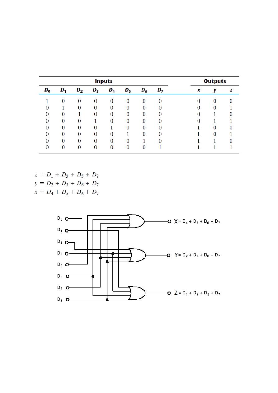
An example of an encoder is the octal-to-binary encoder whose truth table is given as:
This table gives the following Boolean output functions:
The encoder can be implemented with three OR gates:
It may also be noted that D
0
input is not connected to any gate. Thus, output 000 can
be obtained if D
0
= 1 & other input = 0 or if all inputs are equal to zero.
This problem can be resolved by providing one more output to indicate if all inputs are
equal to zero.
Also, this encoder has the limitation that only one input can be active at any time.
Thus, if two inputs are active simultaneously, the output produces an undefined
combination.
For example, if D
3
and D
6
are 1, the output of the encoder will be 111 which does not
represent the case where only D
7
equal to 1 and the rest of the inputs are equal to 0.
To solve this problem, encoder circuits must establish an input priority to ensure that
only one input is encoded.
Priority Encoders
These encoders establish an input priority to ensure that only the highest priority input
is encoded. As an example, if both D
2
and D
4
inputs are logic 1 at the same time, then
output will be according to D
4
only and that is 100.
In addition to the two outputs x and y, the circuit has a third output which is called valid
bit indicator (V).
V = 1 when one or more inputs are equal to 1.
V = 0 there is no valid input.
The other two outputs are not inspected when V equals 0 and are specified as don’t-
care.
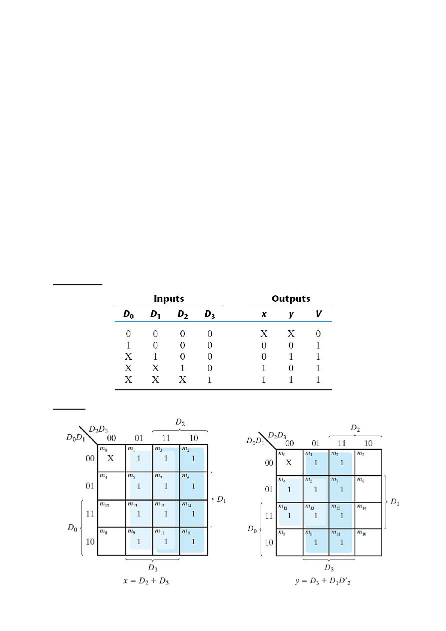
4-2 Priority Encoder
Truth Table
K - Map
The Boolean function for output V is an OR function of all the input variables.
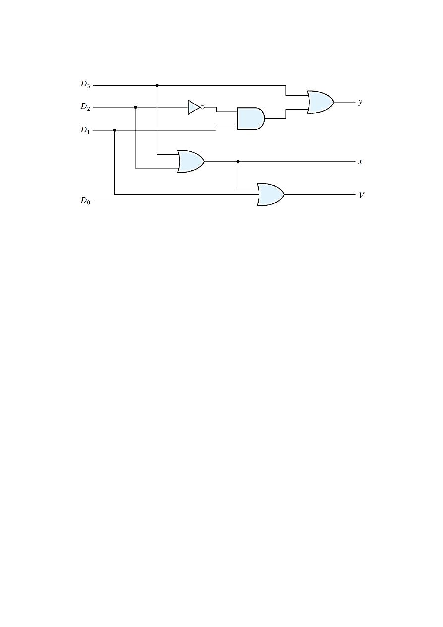
The priority encoder is implemented as follow: