)
Experiment No. (5
Comparator Circuit
:
Objective
Understanding the construction and operation principles of digital comparators.
:
Introduction
At least two numbers are required to perform any comparison .
T
he most simple
form of comparator has two inputs. If the two inputs are called A and B, There are
Three possible outputs:
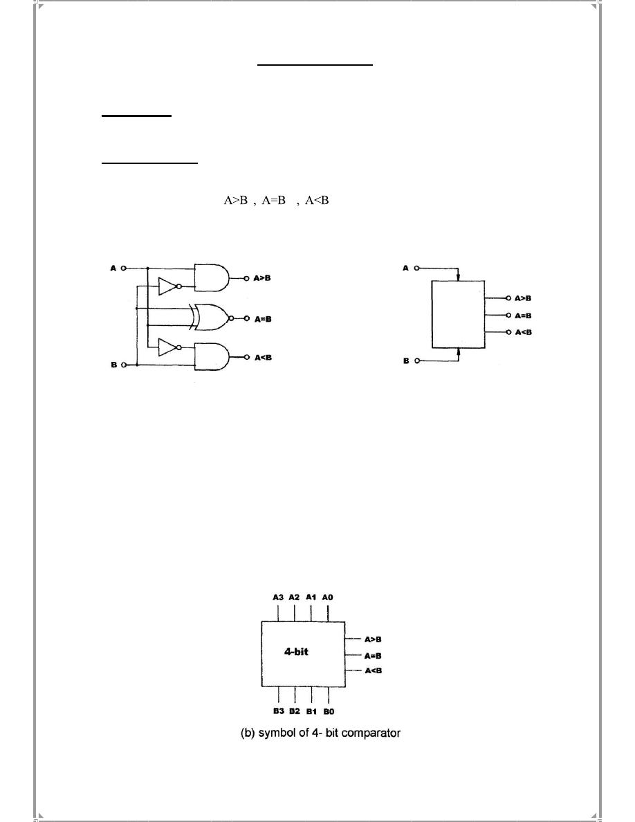
Figure
5
-1 below shows the schematic and symbol of a simple 1-bit comparator.
In a 4-bit comparators , each bit represents 2
3
, 2
2
, 2
1
, 2
0
. Comparisons will start
from the highest bit (2
3
), if input A is higher than input B at the 2
3
bit, the “A>B”
output will be in high state.
If A and B are equal at the 2
3
bit, comparison will be carried out at the next
highest bit (2
2
). If there is still no result at this bit the process is repeated again at the
next bit.
Figure (5-1)
If all the
inputs
are
still
equal,
then
the
“A=B”
output
will
be
in
high
state.
33002
-
31001 Digital Logic Lab; Module KL
-
KL
:
Equipments Required
rocedures:
P
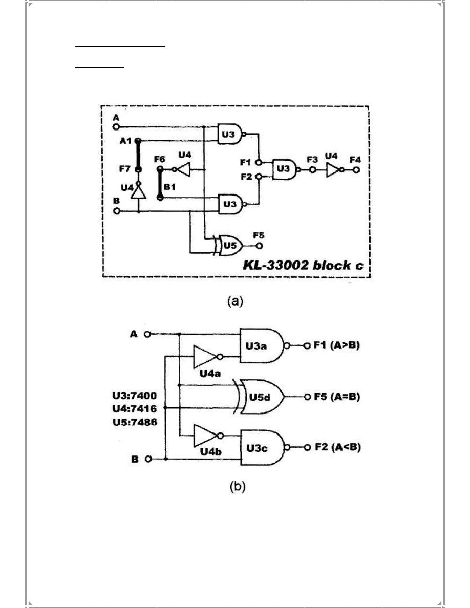
(a) Comparator Constructed with Basic Logic Gates
1. Insert connection clips according to Fig.(5-2).a
Fig.(5-2)
2. Connect inputs A and B to Data Switch SW1 and SW0. Connect outputs Fl, F2, F5
to Logic Indicators LI, L2, L3 respectively.
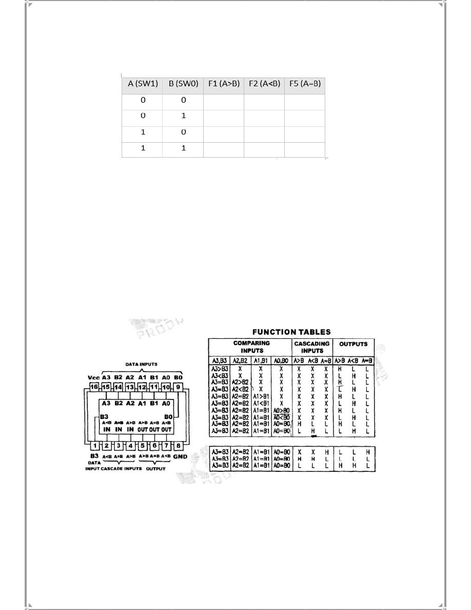
3. Follow the input sequences in table (5-1) then record
and
discuss
the
outputs.
Table
(5-1)
(b) 4-bit Comparator
Constructed
with
TTL
IC
1. Block d of module KL -33002
will
be
used
in
this
section .
U6
is
a
4-bit
comparator IC. Its pin assignment and truth table are shown
below .
This
IC
has
a
cascading inputs
A>B,
A<B,
A=B
which
are
the results of least significant bits
Comparisons . Thus, they have no
effects
unless
the
higher
bits
are
equal.
Using
this
IC
enables
us
to
connect
several
comparators
in
series
(cascaded)
and
hence
compare
more
number
of
bits.
2.
Connect
inputs
A1 - A4
and
B1 -
B4
to
DIP1
and
DlP2.
respectively.
Connect
outputs
A>B,
A<B,
A=B
to
logic
indicators.
Note:
A1
&
B1:
LSB
,
A4
&
B4:
MSB
3.
Follow
the
input
sequences
in
table
(5-2)
and
record
the
outputs.
4.
Design
a
circuit
that
converts
the
active
LOW
output
into
active
HIGH .
Repeat
the
same
sequence
to
fill
the
table
above
again.
Note:
Keep
the
circuit,
we
will
use
it
later
in
part
C.
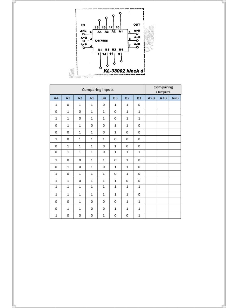
Table (5-2)
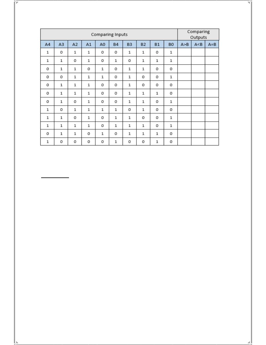
(c)
5-bit
Comparator
Constructed
with
TTL
IC & Logic gate
1.
Connect
inputs
A0,B0
to
the
1-bit
comparator
circuit
designed
using
Active
high
logic
gates.
2.
Connect
the
output
of
the
1-bit
comparator
circuit
to
the
cascaded
input
of
the
4-bit
comparator
IC.
3.
Connect
inputs
A1
-
A4
and
B1
-
B4
of
comparator
IC
to
DIP1
and
DlP2
respectively.
Connect
outputs
A>B,
A<B,
A=B
to
logic
indicators.
Note:
A0
&
B0:
LSB
,
A4
&
B4:
MSB
4.
Follow
the
input
sequences
in
table
(5-3)
and
record
the
outputs.
Discussions:
1.What
is
the
basic
function
of
comparator?
2.
Design
an
8-bit
comparator
using
4-bit
comparator
circuit
with
serial
inputs.
3.
Determine
the
A>B
,
A=B
and
A<B
outputs
for
the
input
numbers.
=
0110
0
A
1
A
2
A
3
A
=
0011
0
B
1
B
2
B
3
B
4.
If
the
result
of
comparison
at
the
highest
bit
of
a
4-bit
comparator
has
one
input
greater
than
all
other
inputs,
which
output
will
be
in
high
state?
a.
>
b.
<
c.
Depends
on
comparisons
at
lower
bits.
Table (5-2)
Table 5-3