
ساليدات امتحان العملي
الصناعة الفصل االول
اعداد
:
سلطان الصفار

Introduction and
classification
Prosthetics & Prosthesis
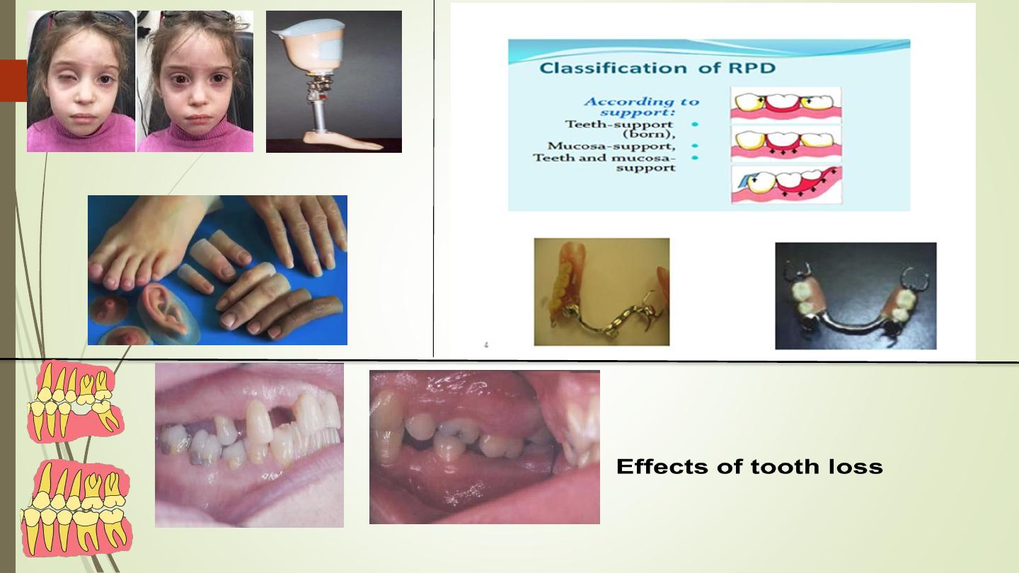
Consequences of tooth loss
Removable
partial
dentures
2.Fixed
restoration
s –
conventio
nal
bridges
Treatment
options
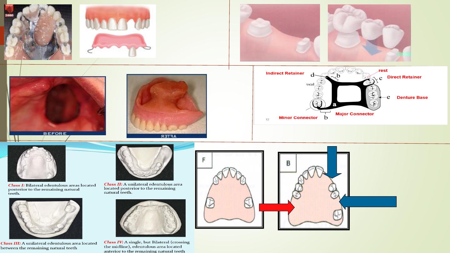
Components of Removable Partial dentur
e
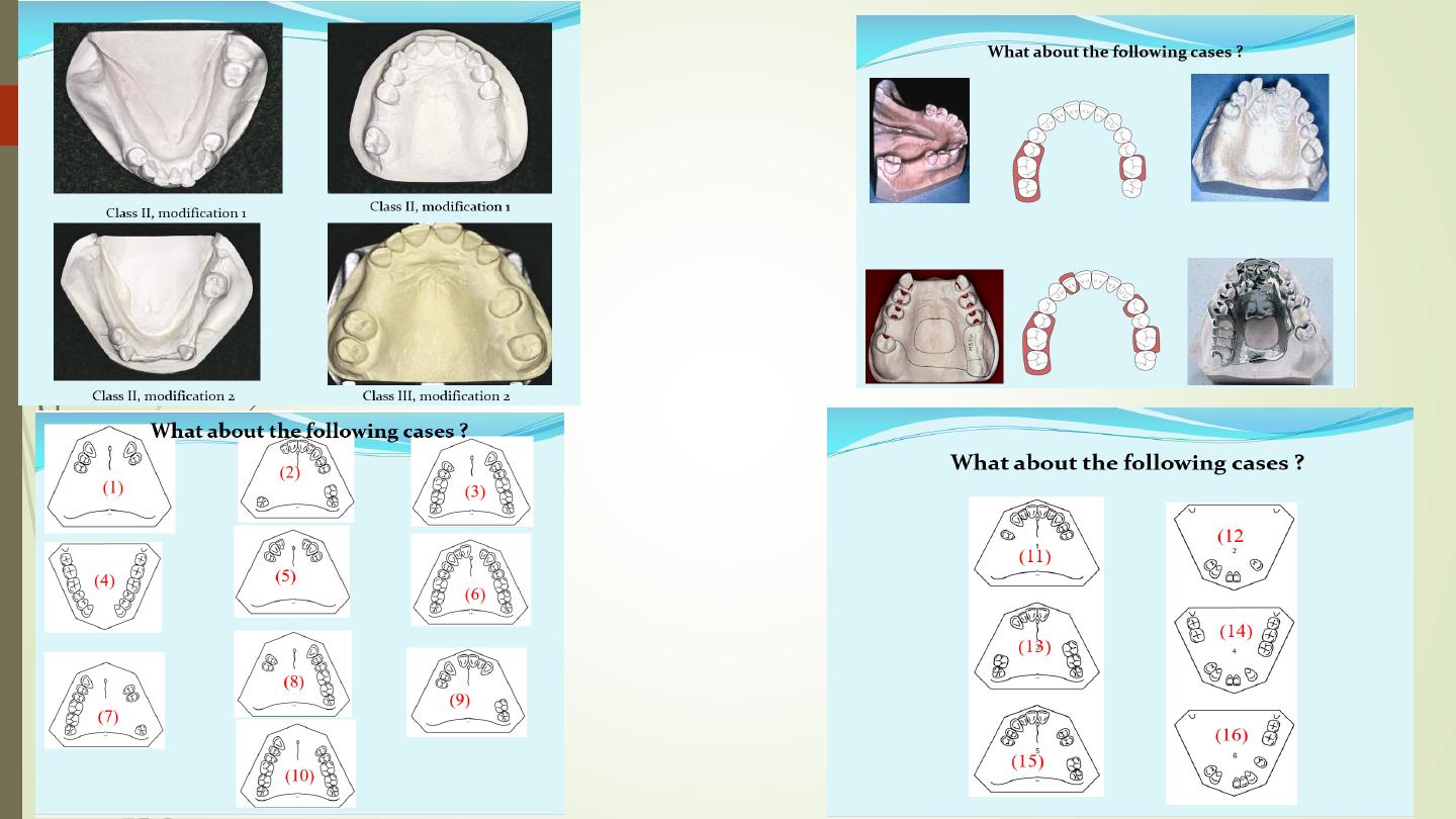
modifications
classification
modifications

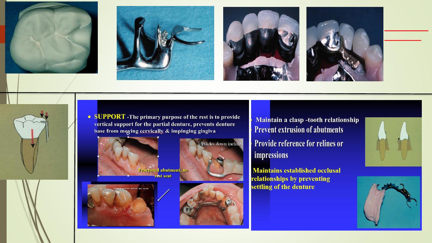
Rests and rest seats
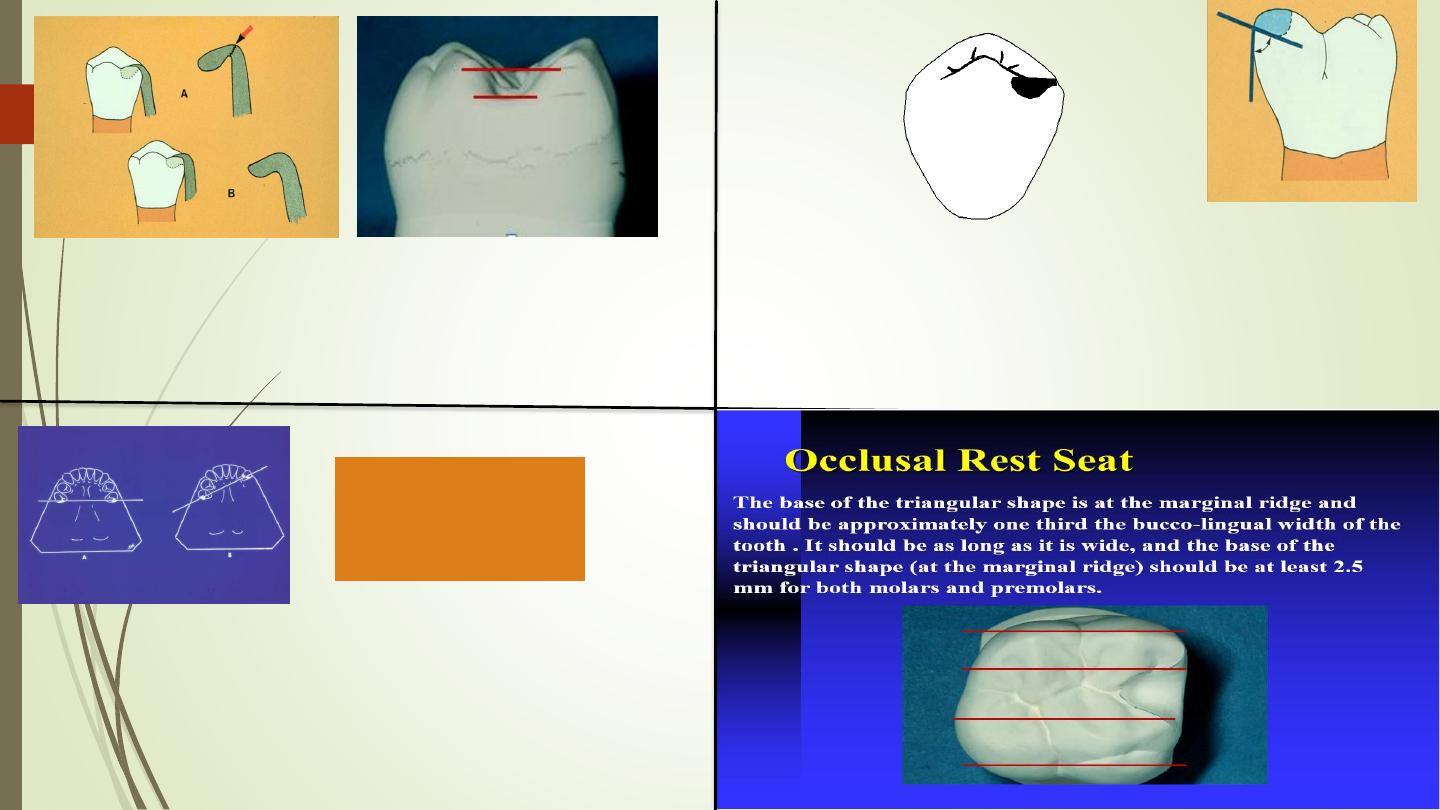
Occlussal Rest seat
(Conventional form)
Intracoronal
(precision)
rest
Rest & its
function
fulcrum line
&Indirect retention
& & rest function in
preventing rotation
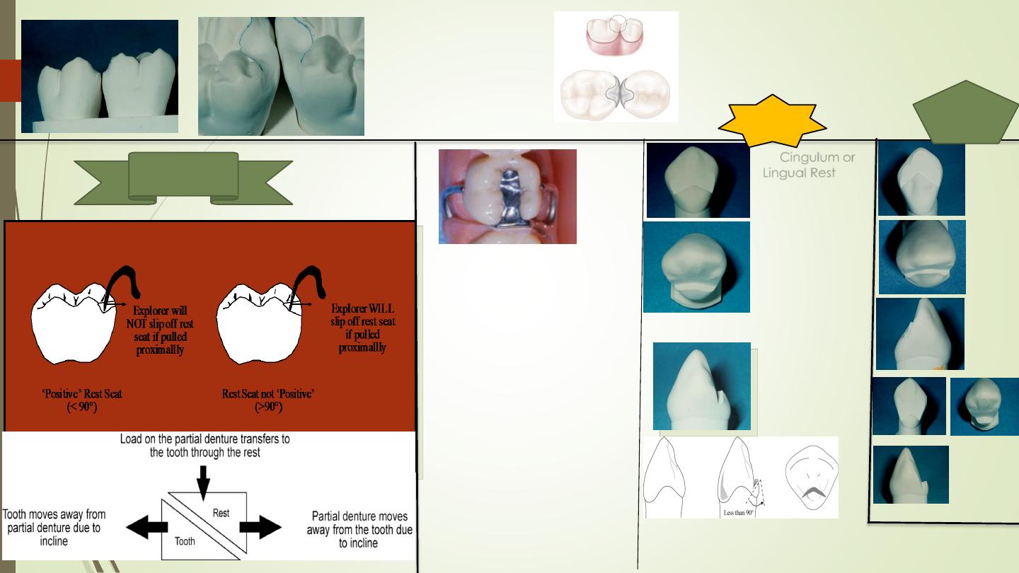
The floor of the rest seat
should be inclined
towards the center of the
tooth, so that the angle
formed by the rest and
the minor connector
should be
less than 90°
The floor of the rest
seat should be
concave or spoon
shaped to create a
ball-and socket-type
of joint
The marginal ridge must be
lowered and rounded to permit a
sufficient bulk of metal to prevent
fracture of the rest from the minor
connector (1 to 1.5 mm)
Double
Embrasure or
inter proximal
rest
Double
Embrasure or
inter proximal
Rest Seat
EXTENDED OCCLUSAL REST
In Kennedy Class II, modification 1,
and Kennedy Class III
situations in
which the most posterior abutment
is a mesially tipped molar, an
extended occlusal rest should be
designed and prepared to
minimize further tipping of the
abutment and to ensure that the
forces are directed down the long
axis of the abutment.
This rest
should extend more than one half
the mesiodistal width of the tooth,
be approximately one third the
buccolingual width of the tooth,
and allow for a minimum of 1-mm
thickness of the metal, and the
preparation should be rounded
with no undercut or sharp angles .
Cingulum or
Lingual Rest
Seats
from the lingual
aspect is a broad
inverted "V'
From the incisal
view the rest seat
is broadest at the
central aspect of
the canine
(approximately
( 1mm).
The borders of
the rest seat are
slightly rounded
to avoid sharp
line angles in its
preparation
Positive
rest seats
The cingulum rest seat should be prepared in the bulk of the cingulum to
minimize tooth reduction.
The cavosurface should be less than 90° to prevent orthodontic
movements of the tooth
.
Cingulu
m rest
False
cingulu
m rests
Too high
cingulum
rest
preparati
on
(un
necessary
tooth
reduction
Preparation
Too Low
(excessive
tooth
reduction)
The interocclusal relationship of a maxillary tooth
with the incisal edge of the opposing mandibular
tooth.
Mounted diagnostic casts should be used to assess this
relationship The cingulum rest seat preparation draw a line on
the lingual surface of the maxillary abutment should be 1.5-2.0
mm below this line to allow for adequate framework strength.
Maxillary Cingulum Rest Seats overlapping
. When a
deep vertical overlap exists, care must be taken to
ensure that the mandibular tooth does not prematurely
contact the area of the planned metal framework.
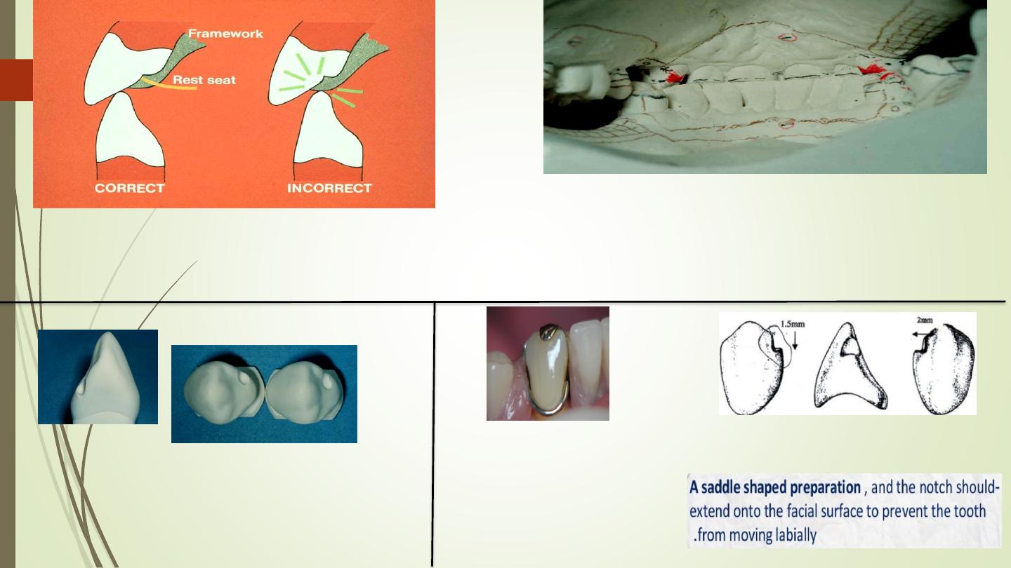
Rounded rest, prepared
on mesial of the canine
teeth when typical
cingulum rest is
contraindicated
Incisal Rest
,
Inferior to
lingual rests mechanically
& esthetically not be used
unless it is impossible to
place a lingual rest seat or
a composite bonded rest
seat. It is used as indirect
retainer
Incisal rest seat
or preparation

surveying
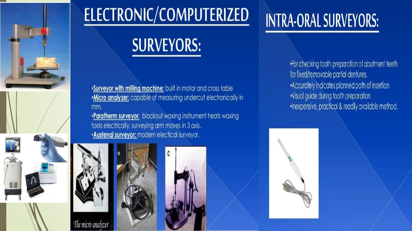
Manual
Dental
surveyor
CAD/CAM SYSTEM.
With intra oral
surveying camera
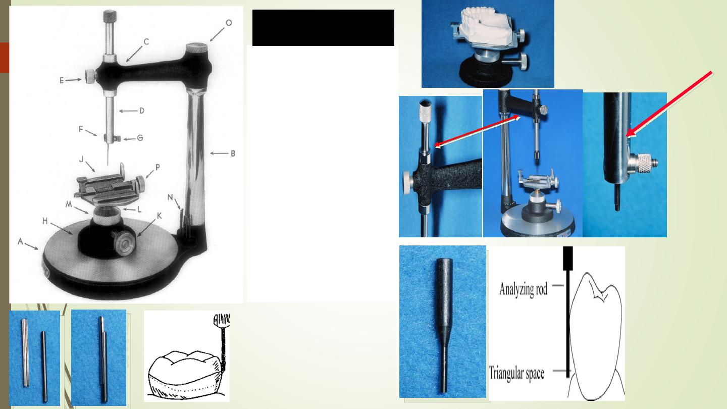
B-Vertical Upright Column
C-Cross Arm with Spindle
Housing
D-The Vertical Spindle
With Tool Holder
E- Screw To Lock The
Spindle
F- Tool adaptor Holder
G- Surveying tool holder
J- Model Clamp
K- Model table lock nut
L- Model rotating ball &
socket
M- Ball rotating ring
N- Tool Rack
O- Storage Compartment
P- Model lock nut
Parts of a Dental
Surveyor
Surveying
Table
Surveying
Arm(all)
Analaysing
rod
Carbon Markers
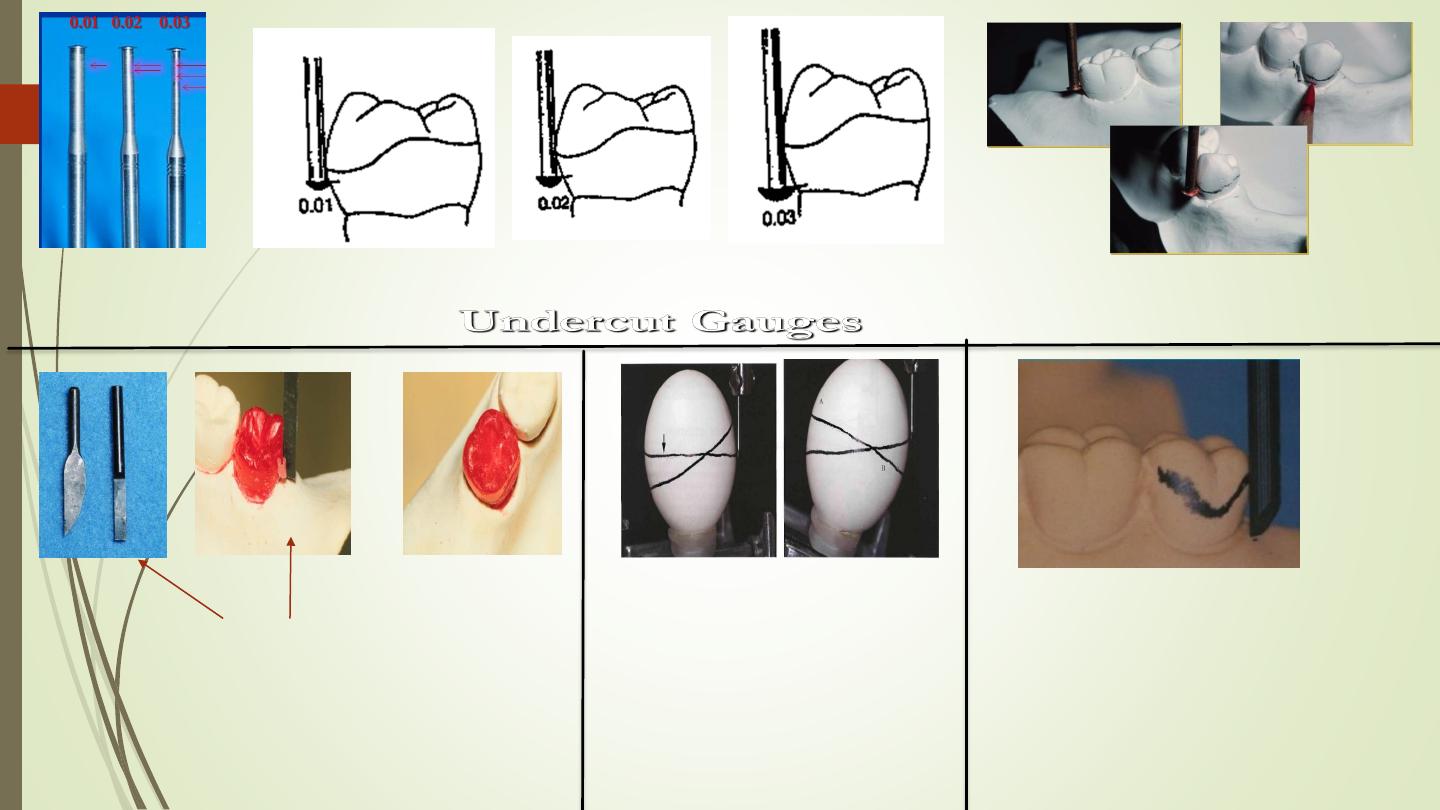
Wax Trimmer
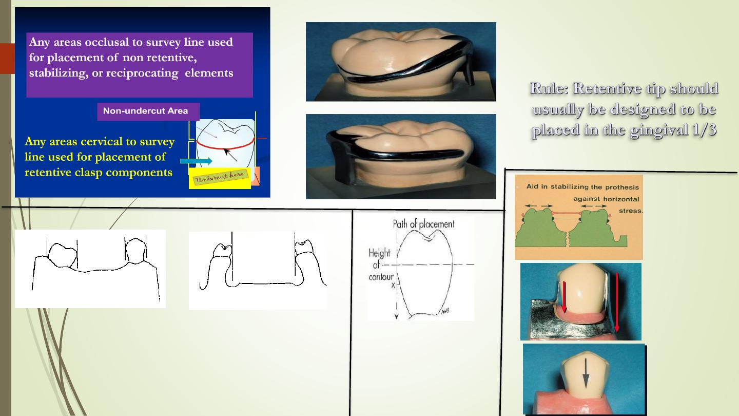
Height of
Contour (HOC)
or survey line
survey line
Tooth
Undercuts
Soft Tissues or bony
Undercuts
(on lingual
side of ridge)
Angle of
Cervical
Converge
nce
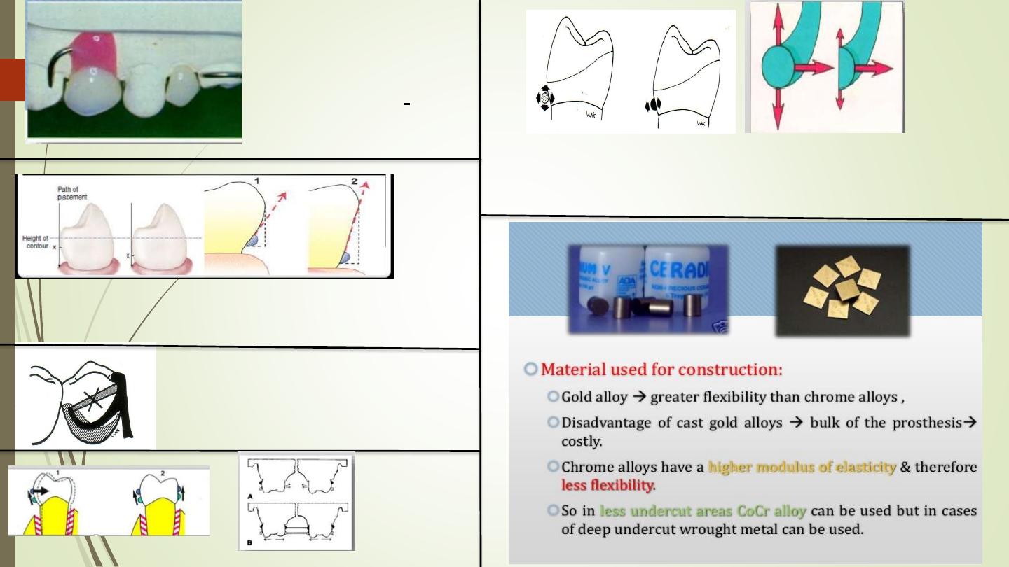
Path of
insertion
(or
removal)
Types of
undercuts
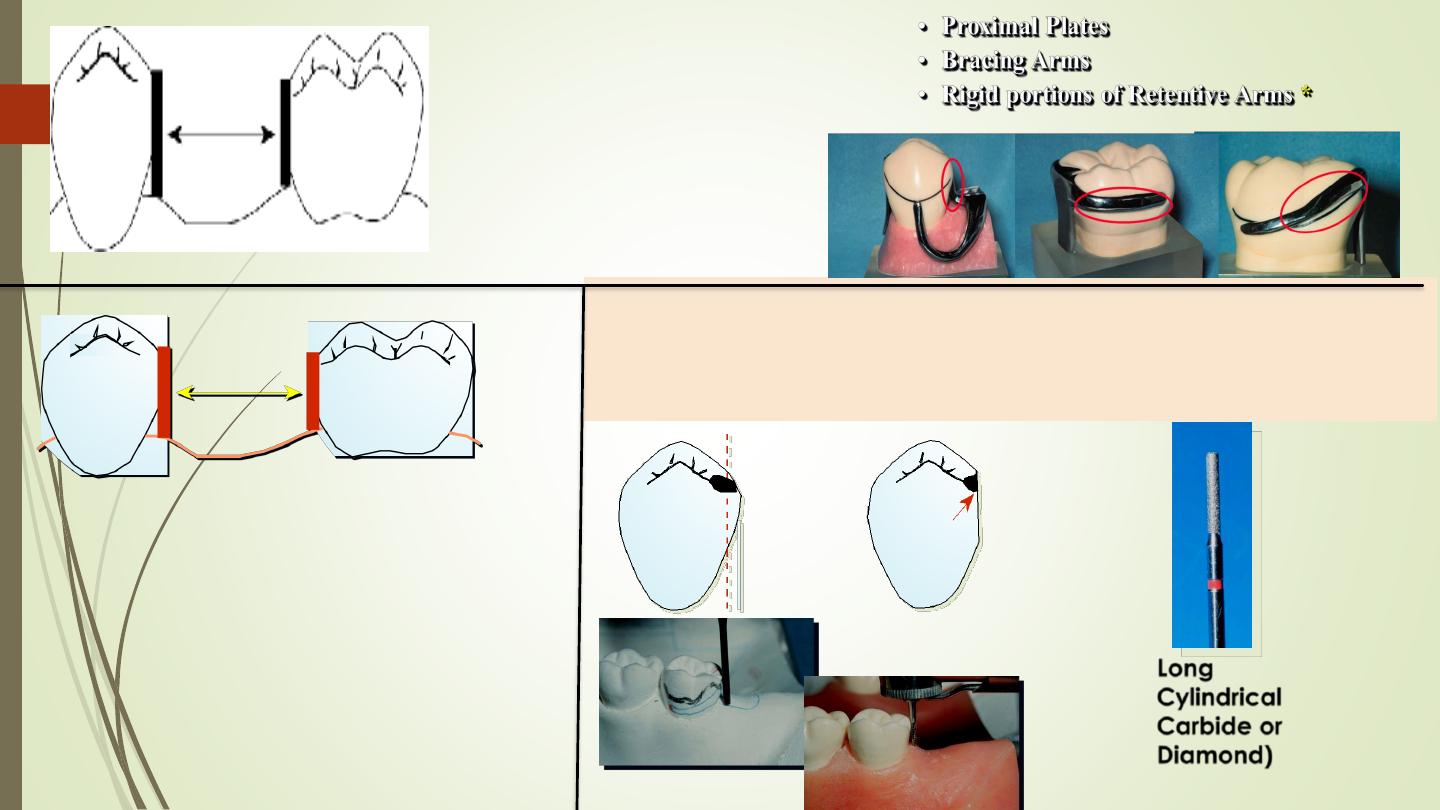
Preperation Of Guiding Planes
Guidin
g
planes
Guiding plane is Most effective when:
A- Parallel to each other
B- More than one common axial surface
C- Directly opposing each other
D- Prepared on several teeth
E- Cover a large surface
area(proximal & lingual)
Long
Cylindrical
Carbide or
Diamond)
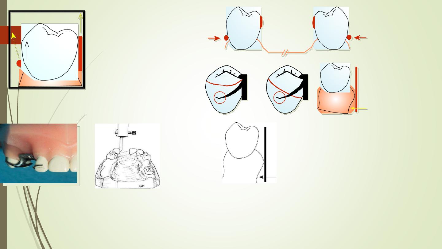
Retentive Areas
Retentive arm should have a
different path of escapement
than guiding plane (path of
removal), so retentive arm must
be forced to flex over a convex
surface during placement and
removal (retention)
For a clasp to be retentive, its
path of escapement must be
other than parallel to the path
of removal of the denture itself.
Retentive
undercuts
equalized
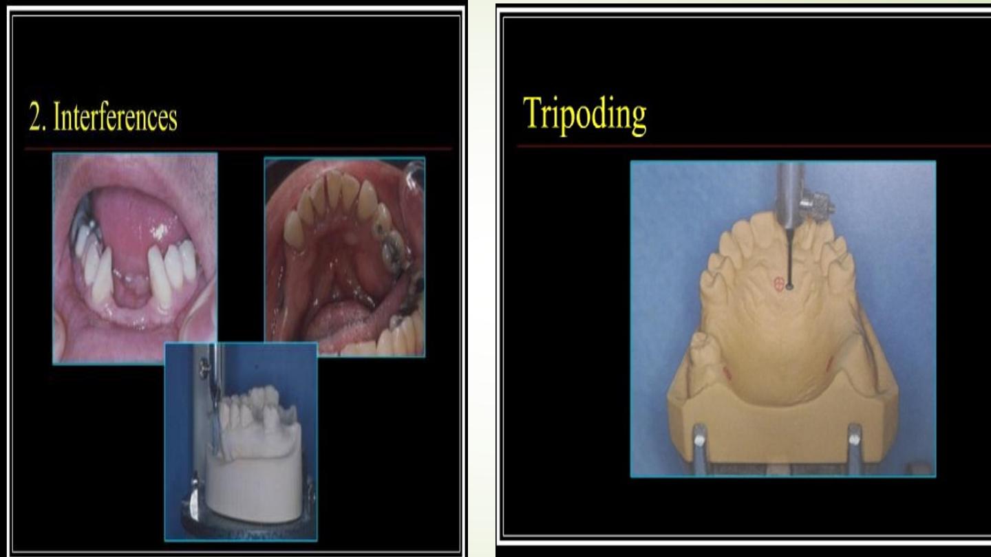
interference
Prosthesis must be
designed so that it
may be placed and
removed without
encountering
tooth
or
soft tissue
interference
Interference
Bony
undercuts
Esthetics
A path of insertion should be
selected to provide the most esthetic placement
of artificial teeth and the least amount of
visible metal on the abutment teeth . the
retentive undercut and the height of contour
are not placed too far occlusally

Direct retainers
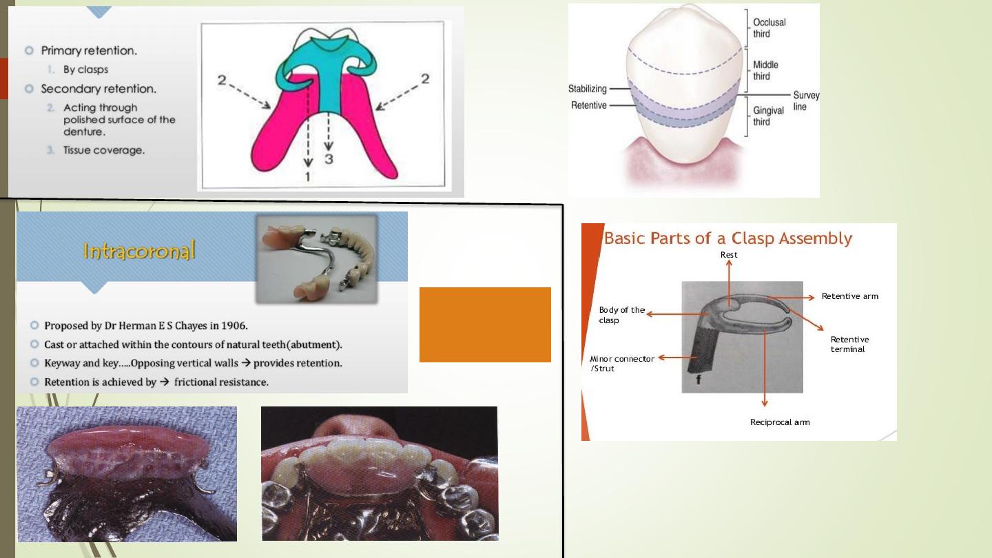
Intracoronal
(precision
attachemen
ts)
Extracoronal
retainer
(Infrabulge clasp)
the angle of the
cervical convergence
How far is the clasp
terminal is placed in angle
of cervical convergence
Diameter of
clasp arm
Cross sectional form of the clasp ar
round, half round )
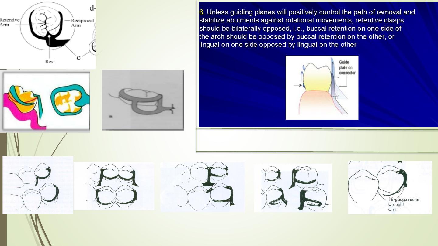
reciprocati
on
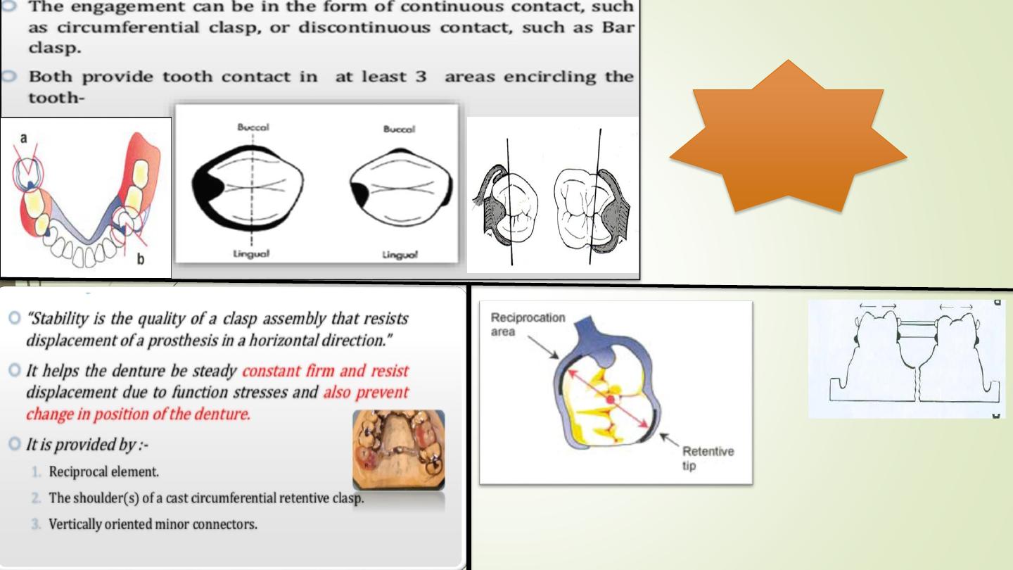
The
principle of
encirclemen
t
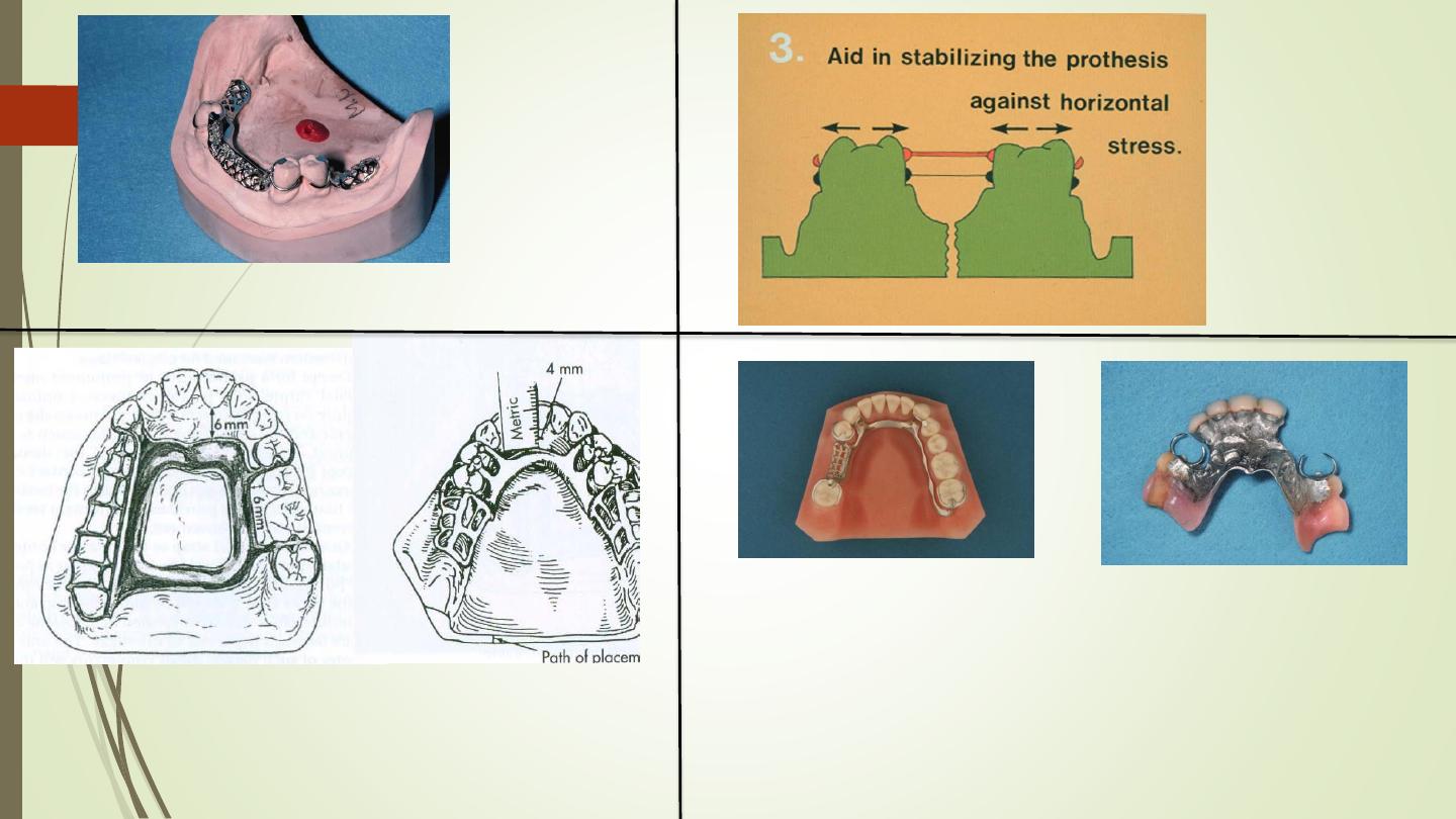
Stabilizing and
reciprocal
components must
be rigidly connected
bilaterally (cross-
arch)
Each retentive terminal should be
opposed by reciprocal component
capable of resisting any transient
pressures exerted by the retentive
arm during placement and removal
Suprabulge
circumferential or
C-clasp (direct
retainer)
Ring
clasp
*
Ring clasp with
auxiliary bracing
arm*
Back-action
clasp*
Multiple
Clasp*
Half-and-
half clasp*
Reverse-
action
clasp*.
Combinatio
clasp*
C-claspال
يفضل
كتابة جميع
االنواع بنفس صيغة
(*)
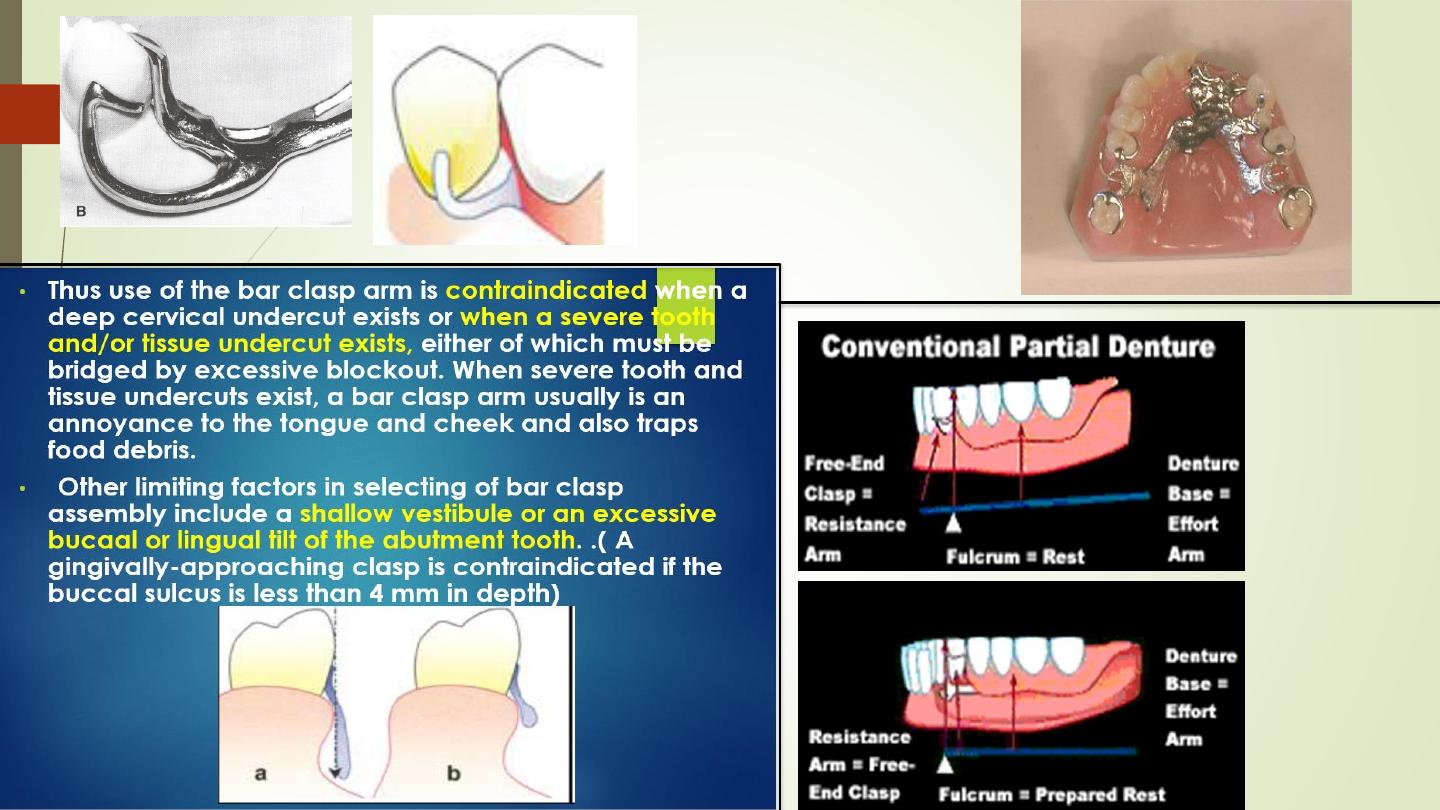
Bar clasps
RPI AND RPA VS
CONVENTIONA
L
RPI
Clasp retention is base on
the resistance of the metal.
For a clasp to be retentive
<it must be placed in an
undercut area of the tooth
where it is forced to deform
upon application of vertical
force
Indirect retainers
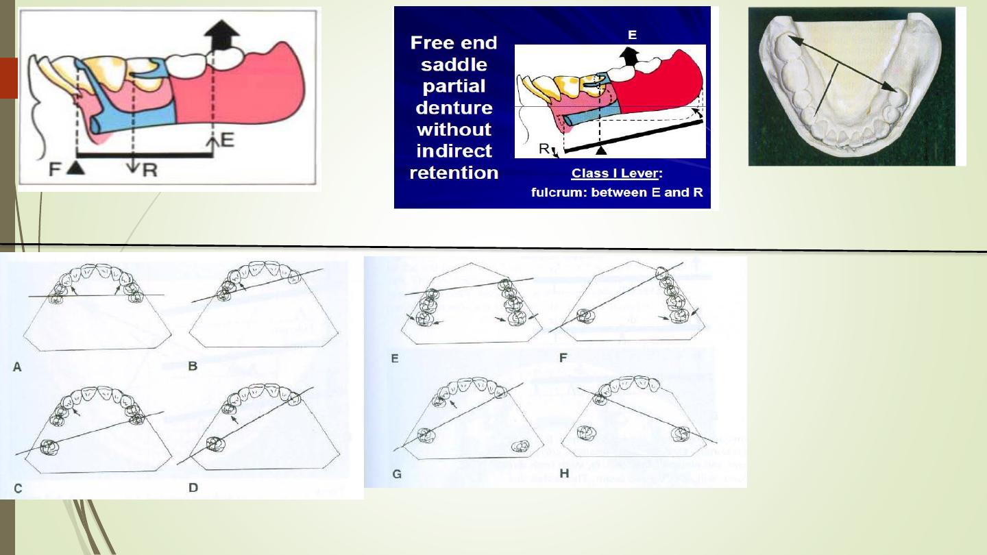
Free end saddle partial
denture with indirect retention
FULCRUM LINE
&
Indirect
retainers should be placed
as far as possible from the
distal extension base
Location of fulcrum lines for
different classes of RPDs
1)Class1-passes through most
posterior abutments
2) Class2-passes diagonally
through most posterior teeth
on one side and abutment on
distal extention side
3) Class3-passes through two
principal abutments
4)Class4-passes through two
abutments adjacent to the
edentulous
space
Effectiveness and Placement:
- Usually it is a rest seat placed anterior the the fulcrum line on the side opposite the
extension base. Theoretically, the further anterior the rest seat is placed the more
effective it is. The rest seat is usually located on a canine or first premolar mesial fossae.
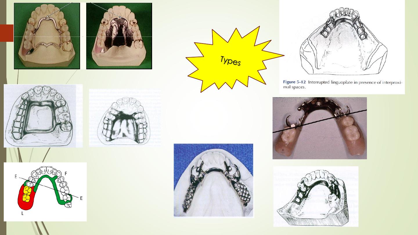
Auxiliary
occlusal rest
indirect retainer
REST
(CINGULUM
REST OR
LINGUAL REST
indirect
retainer
CANINE EXTENSION FROM
THE OCCLUSAL REST
.
Cingulum
bars
( Continuous
bars) and
Linguoplates
Modification
Areas as
indirect retainer
Rugae
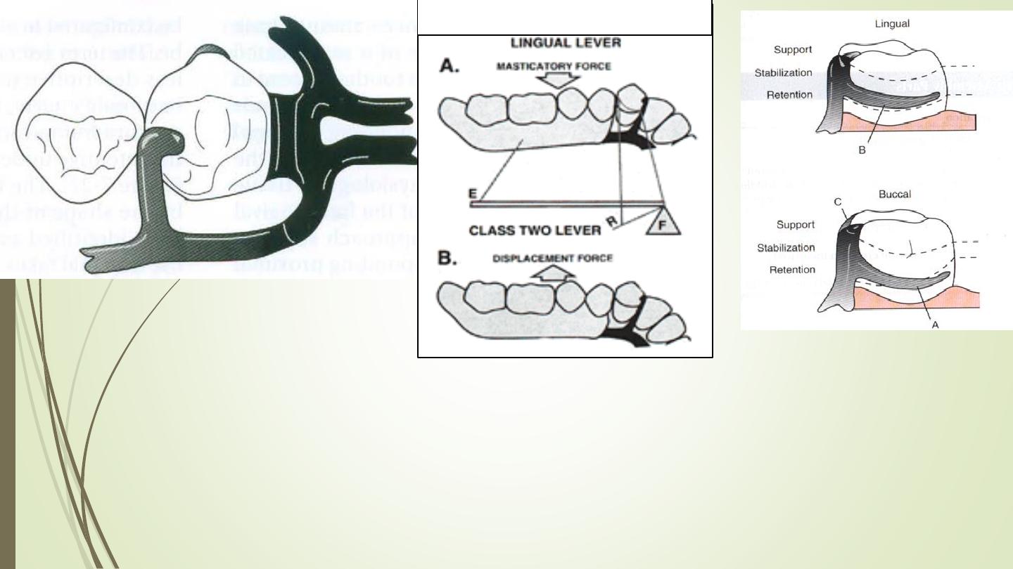
Support
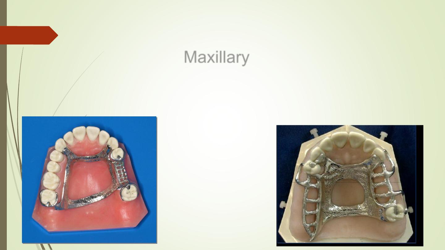
Maxillary
Major Connector
Gingival protection
Cross-Arch Stabilization
principle in major
connectors
(Counterleverage
To Increase Rigidity
Increase the bulk as the length increases
Corrugate linguo-plate or rugae areas
Non-Interference with the Soft
Tissues
It does not interfere with the tongue
and not impinge on oral tissue
when the restoration is placed,
removed, or rotates in function
Avoid terminating on Free gingival
margin
.
Minimize
Food
Impaction
Eliminate "traps"Locate margins away from
the FGM
or large concavities where food can collect
a major connector must promote patient comfort
Smooth transition from connector to denture base - butt joint
promote patient comfort
Line angles and edges should be smooth and rounded
Borders should not interfere with speech
Single palatal bar
Single palatal
strap
Single Palatal Strap
Strap should
be 8mm wide
or
approximately
as wide as the
combined
width of a
maxillary
premolar and
first molar
Single Palatal Strap
Usually use for Class III
Combination anterior and posterior
palatal strap type connector
Use in most
cases
Especially
torus
palatinus
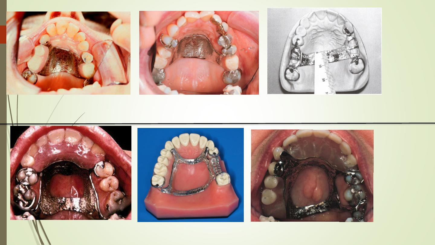
Anterioposteior palatal strap
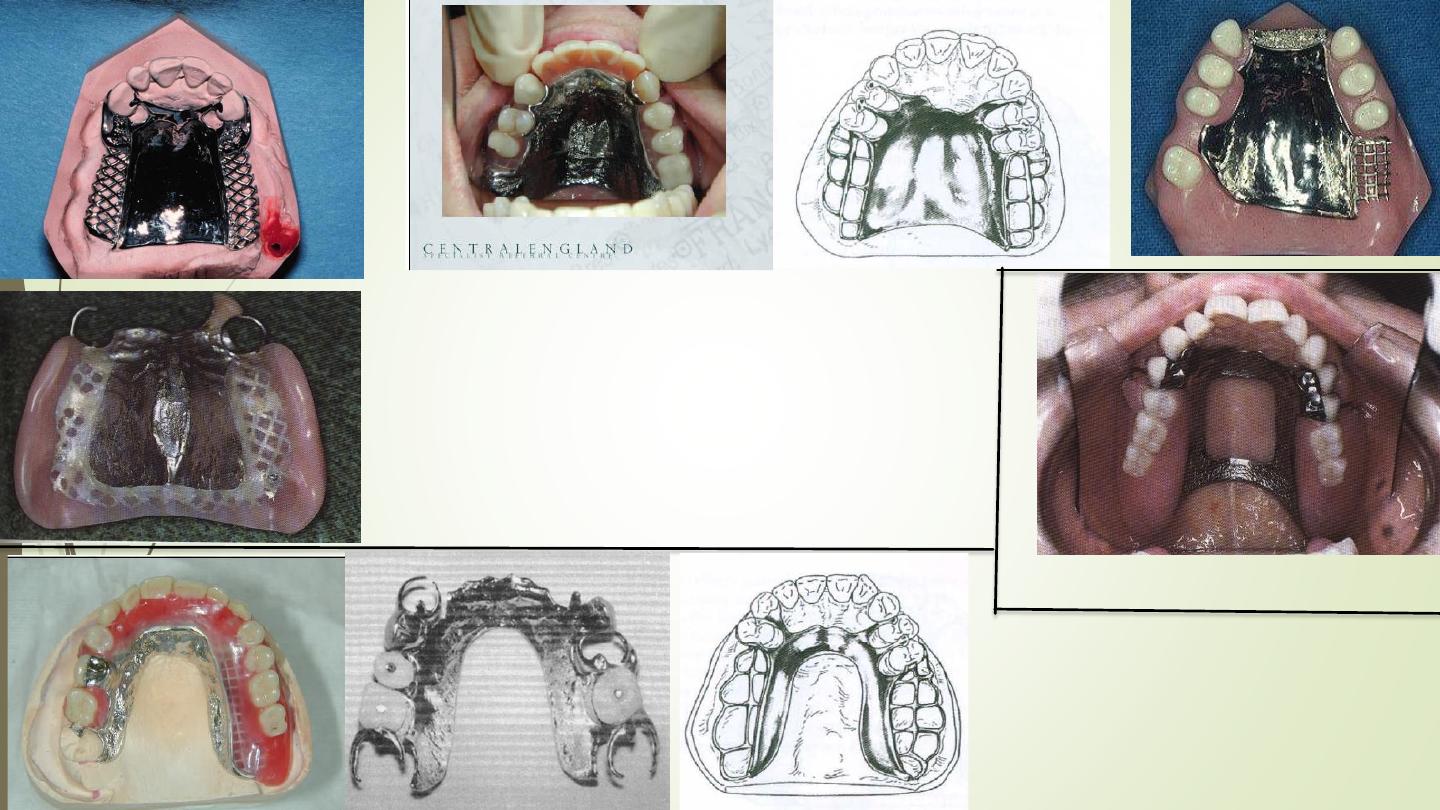
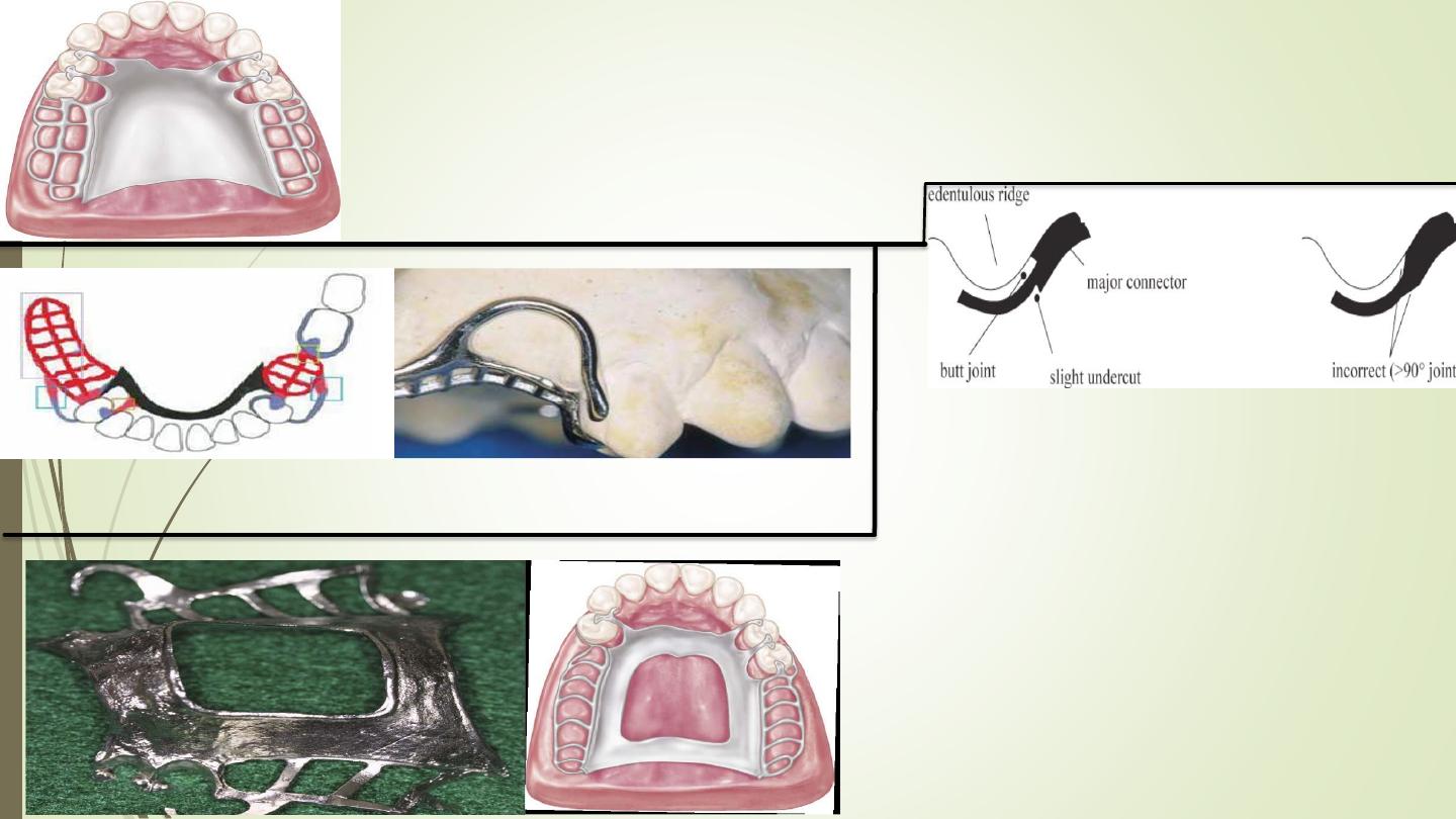
PALATAL MAJOR CONNECTOR
COMPLETE PALATAL
COVERAGE MAJOR
CONNECTOR
Or The complete palatal
plate
U-SHAPED PALATAL
MAJOR CONNECTOR
Use only where torus
prohibits other connectors
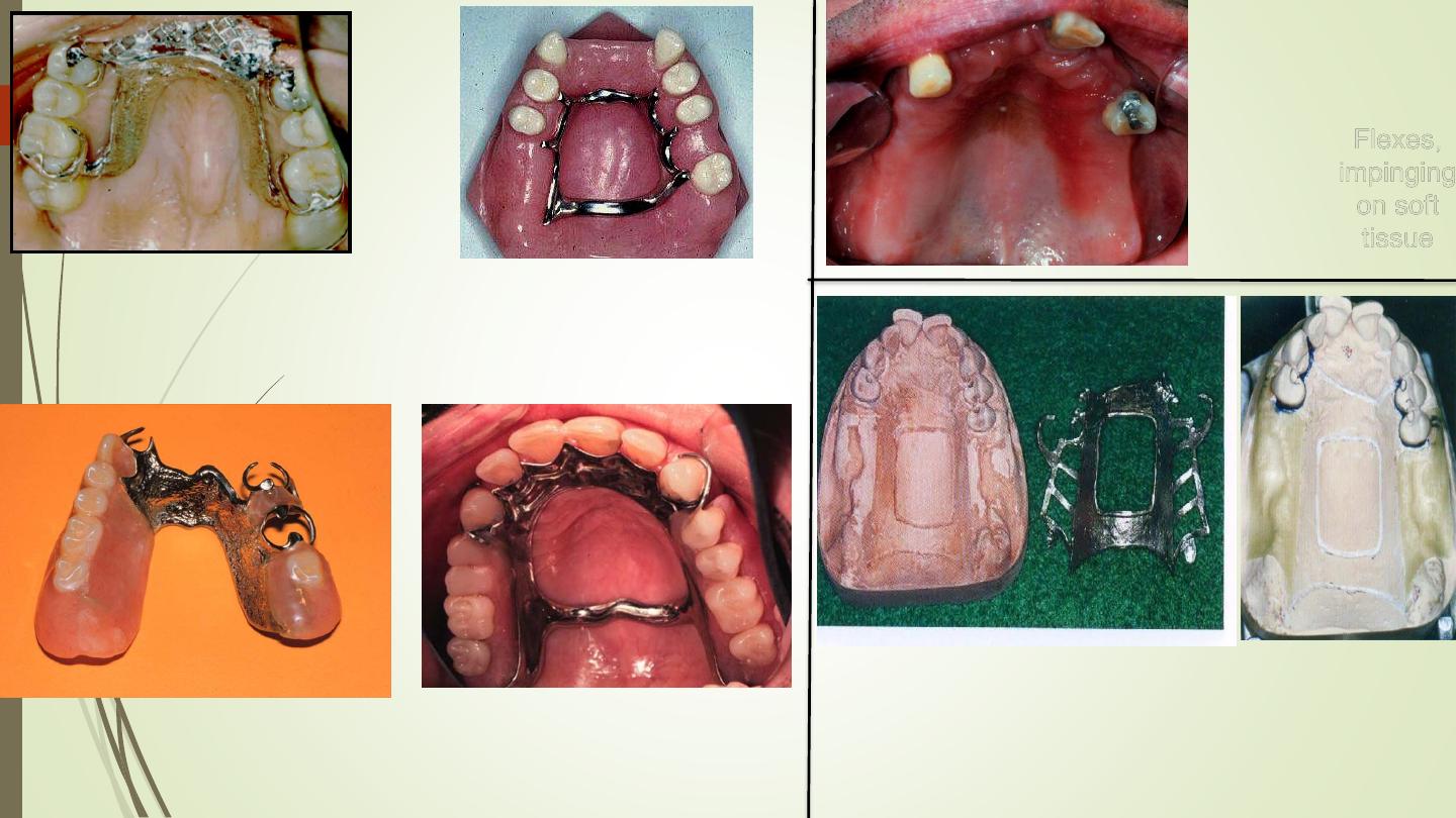
Flexes,
impinging
on soft
tissue
U-SHAPED PALATAL
MAJOR CONNECTOR
Use only where torus
prohibits other connectors
(
U-Shaped or "Horse-Shoe"
Palatal Connector
)
Never
use
unless absolutely necessary
Combination Anterior-
posterior palatal bar
Anterior-Posterior Palatal
Bar
Beading of the
Maxillary Cast
Special Structural Requirements of
Mandibular major connectors:
1. relief must be routinely provided
between mandibular major
connector and the soft tissue.
2. because of the need for relief under
all mandibular major connectors,
Beading is never indicated
.
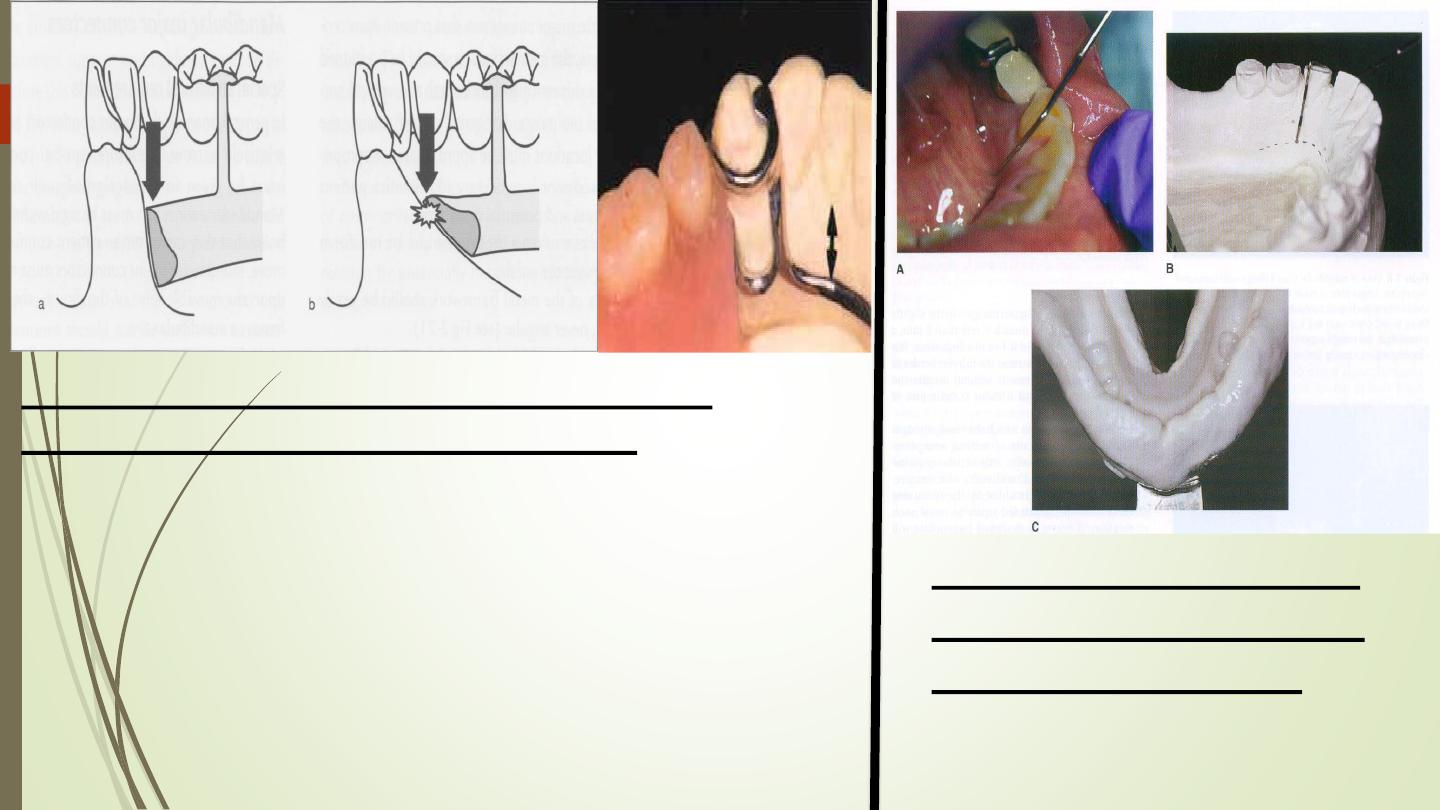
Amount of relief depend on:
Determination of the
relative height of the
floor of the mouth
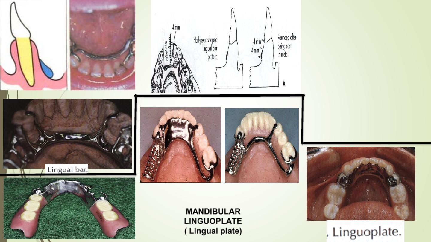
Lingual Bar
Characteristics and
location
(1) Half-pear shaped with
bulkiest portion inferiorly
located.
(2) Superior border
tapered to soft tissue.
(3) Superior border
located at least 4 mm
inferior to gingival margins
and more if possible.
(4) Inferior border located
at the ascertained height
of the alveolar lingual
sulcus when the patient's
tongue is slightly elevated.
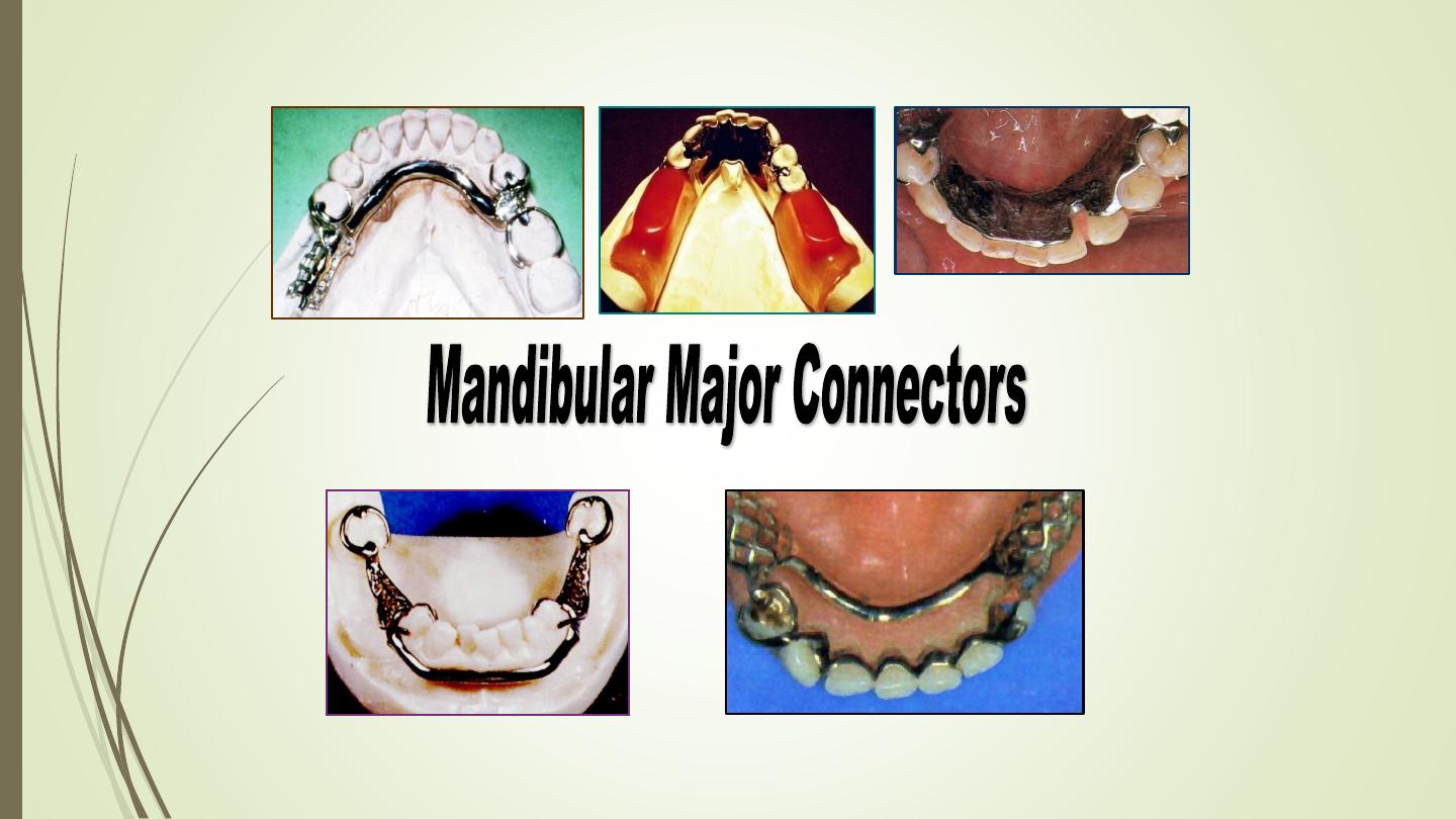
MANDIBULAR
LlNGUOPLATE
( Lingual plate)
correct
incorrect
Characteristics and Location
(
1
) Half-pear shaped with bulkiest portion
inferiorly located.
(2)
Thin metal apron (sold piece) extending
superiorly to contact cingula of anterior teeth
and lingual surfaces of involved posterior
teeth at their height of contour.
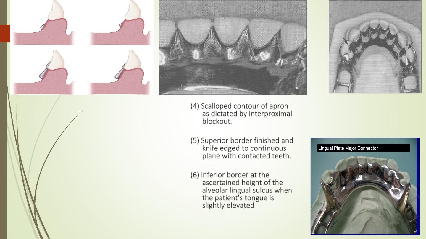
(3)
Apron extended interproximally to the
height of contact points, i.e., closing
interproximal spaces.
(4)
Scalloped contour of apron
as dictated by interproximal
blockout.
(5)
Superior border finished and
knife edged to continuous
plane with contacted teeth.
(6)
inferior border at the
ascertained height of the
alveolar lingual sulcus when
the patient's tongue is
slightly elevated
lingual plate must be
supported by rests located
no farther posterior than
the mesial fossae of first
premolars
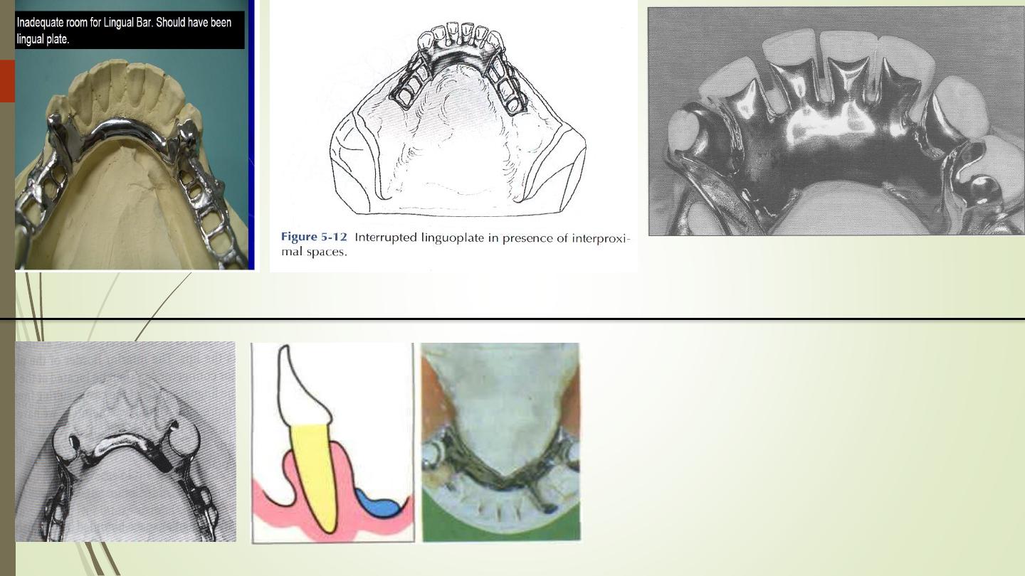
lingual plate may include "step
backs" to minimize or eliminate the
appearance of metal
.
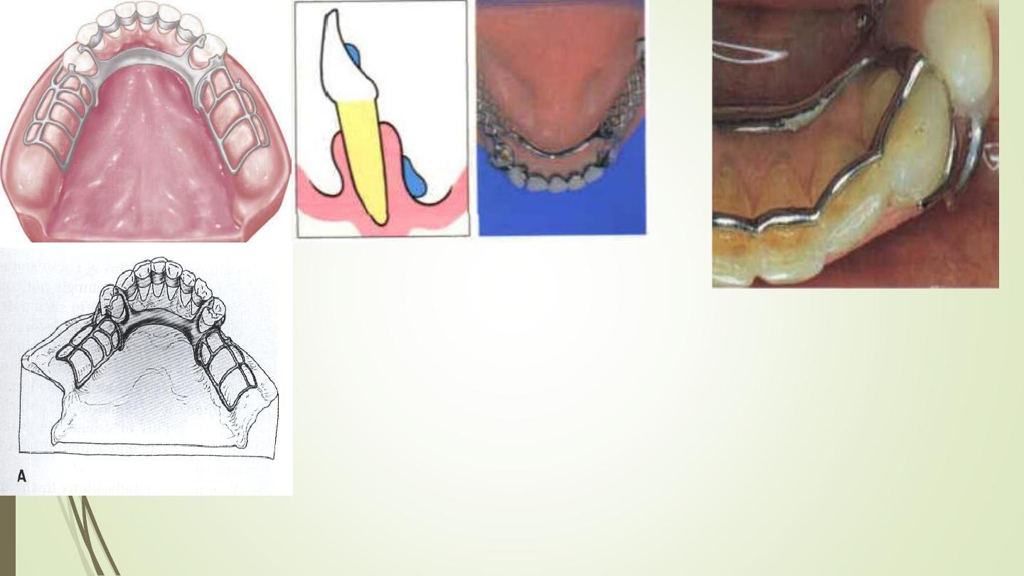
Sublingual
bar major
connector
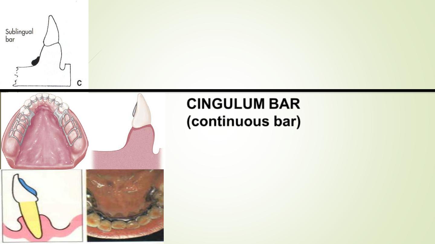
sublingual bar major connector
Characteristics and Location
A modification of the lingual bar that has been demonstrated to be useful when the height
of the floor of the mouth does not allow placement of the superior border of the bar at
least 4 mm below the free gingival margin is the
sublingual bar.
The bar shape remains essentially the same as that of a lingual bar, but placement is
inferior and posterior to the usual placement of a lingual bar, lying over and parallel to
the anterior floor of the mouth.
CINGULUM BAR
(continuous bar)
Characteristics and location
(l)
Thin, narrow, ( 3 mm) metal strap located on
cingula of anterior teeth, scalloped to follow
interproximal embrasures with inferior and
superior borders tapered to tooth Surfaces.
(2)
Originates bilaterally from incisal , lingual,
or occlusal rests of adjacent principal
abutments.
MANDIBULAR LINGUAL BAR WITH CINGULUM
BAR (Double lingual bar, Kennedy
bar)
Characteristics and location
(1) Conventionally shaped and located Same as lingual
bar major connector component when possible.
(2) Thin, narrow (3 mm) metal strap located on cingula
of anterior teeth, scalloped to follow interproximal
embrasures with inferior and superior borders
tapered to tooth surfaces.
(3) Originates bilaterally from incisal, lingual, or occlusal
rests of adjacent principal abutments
MANDIBULAR LINGUAL BAR
WITH CINGULUM BAR (Double
lingual bar, Kennedy bar)
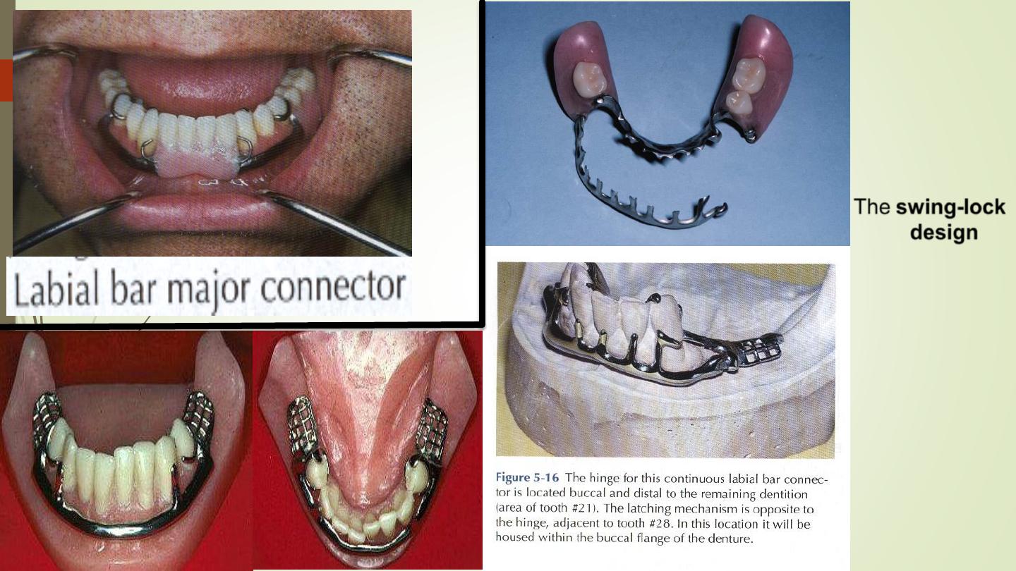
The swing-lock
design
is a variation of
the labial bar.
Hinge at one
end and
locking
device at the
opposite end
.
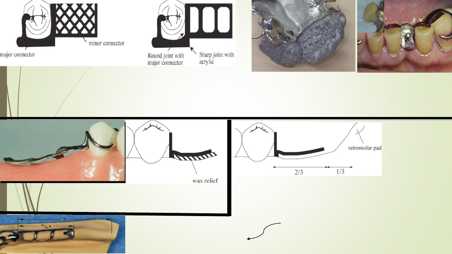
Minor
Connectors
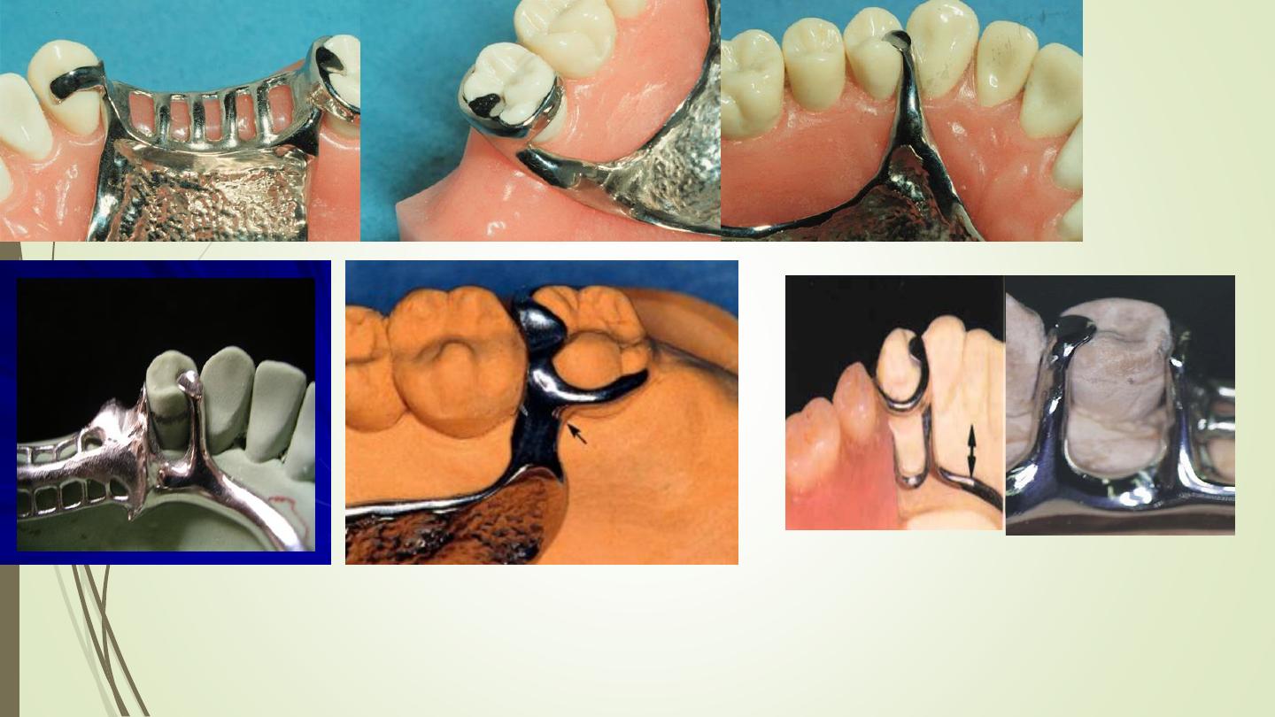
The minor
connector:
• Connects
components to
the major
connector
• Direct retainer
• Indirect retainer
• Rest
Minor connector
must not impinge on marginal gingival tissues
.
Slight relief is required when crossing the gingival margin
especially in tooth-mucosa borne dentures.
Minor connectors should be located at least
5mm
from other vertical components.
Embrasure
Minor
Connectors
Between two adjacent
teeth
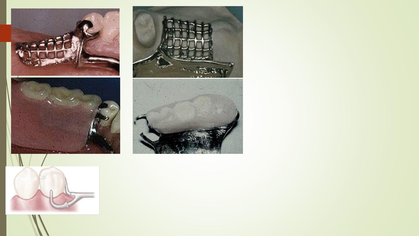
Gridwork minor connectors
that connect the denture
base and teeth to the major
connector.
Mesh type
Triangular shaped in cross
section
Joins major connector at
right angles
Relief placed so connector
not directly on soft tissue
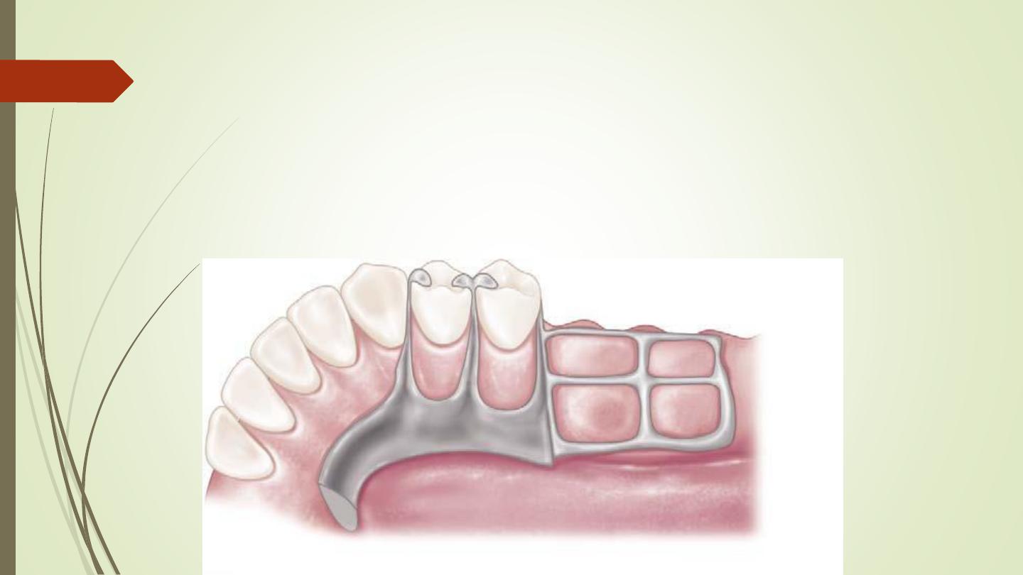
Proximal minor connector
mesial and distal minor
connectors and proximal plates
adjacent to the edentulous areas
should swing back to join the
major connector in a rounded
acute angle in order to increase
gingival exposure.
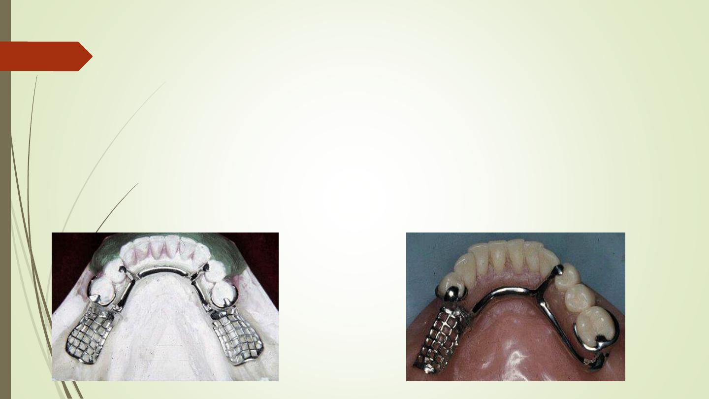
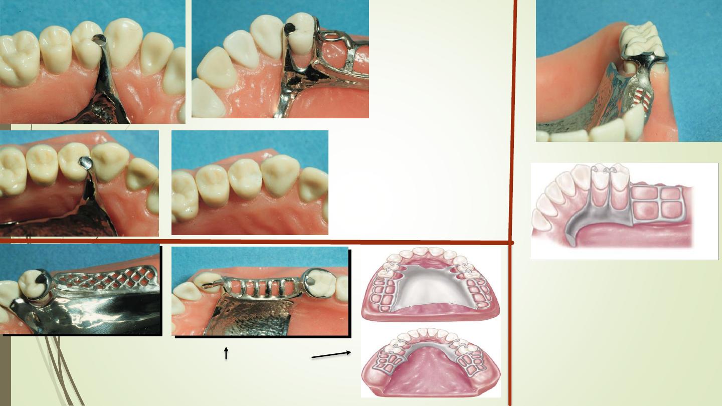
Lattice Type
Gridwork Minor Connectors
Open lattice work
mesh types
Bead, wire, or nail-head minor connectors
Gridwork Relief
Usually one thickness of baseplate wax is about
1 mm
of relief sufficient
The minor connector for the mandibular
distal extension base should extend
posteriorly about two-thirds the length of
the edentulous ridge and should have
elements on both lingual and buccal
surfaces.
Mandibular Gridwork Design
هنا
ايض
ا
Minor connectors for maxillary distal
extension denture bases should
extend the entire length of the residual
ridge and should be of a ladderlike
and loop design.
Those that serve as an approach arm for
a vertical projection or bar-type clasp.
The junction of gridworks to the major
connector should be in the form of a
butt joint with a slight undercut in the
metal. The angle formed by the metal
at this juncture must not be greater
than 90 degrees.
If these butt joints occur on the
outer aspect of the major
connector they are called external
finish lines; if they are on the
internal or tissue side of the major
connector ,they are internal finish
lines .
Angle the
finish line
forms with
major
connector
– less than
90 degree.
90-degree butt-
type joints
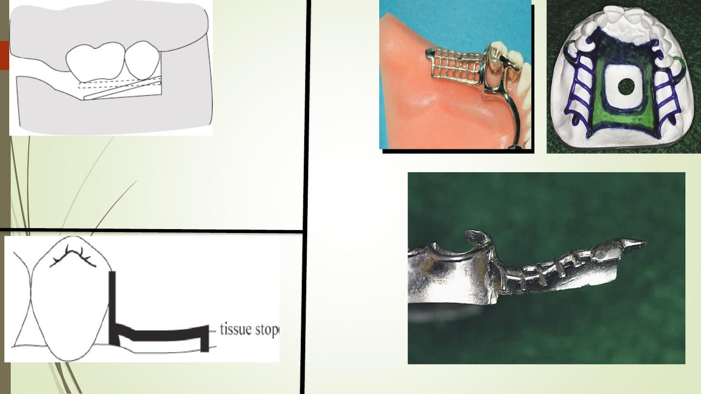
Tissue stop
Closure of the flask under
hydraulic pressure can
causes distortion of the
framework, pushing it
tissue ward
.
وحدثت المعجزة وكمل الملف