
NiTi intracanal
instruments
Balsam M. Mirdan

Classification
They are divide in to 6 Groups:
Group I: Manually-operated instruments, such as barbed broaches
and K-type and H-type instruments.
Group II: Low-speed instruments with a latch-type attachment.
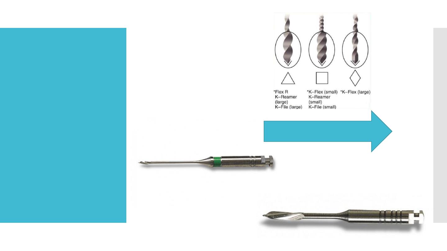
Typical instruments in this group are Gates-Glidden (GG) burs and
Peeso reamers. They are typically used in the coronal part of the
canal and never used in a canal curvature.
Group III: Engine-driven nickel-titanium rotary instruments. They
consist of a rotating blade that can safely be operated in, and adapt
itself to, curved root canals. Most engine- driven instruments
available today belong to this group.
classification
Increase cutting efficiency
Gates glidden

Classification
Group IV: Engine-driven instruments that adapt themselves three-
dimensionally to the shape of the root canal. Like other nickel-
titanium instruments, they adapt to the shape of the root canal
longitudinally but additionally they adapt also to the cross-section
of the root canal. There is currently only one instrument in this
group: the self-adjusting file (SAF).
Group V: Engine-driven reciprocating instruments.
Group VI: Ultrasonic instruments.
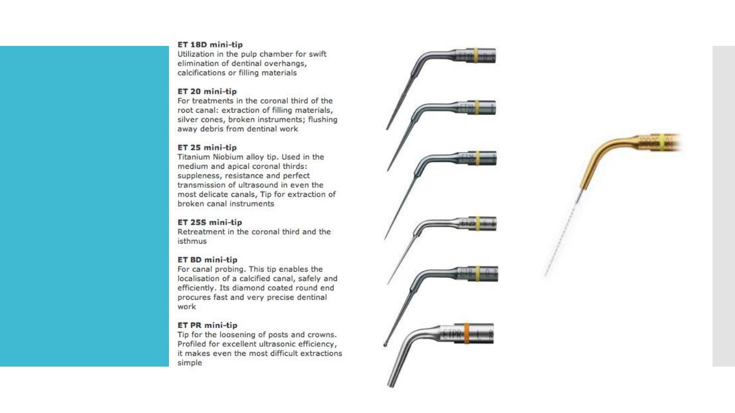
Ultra sound
tips
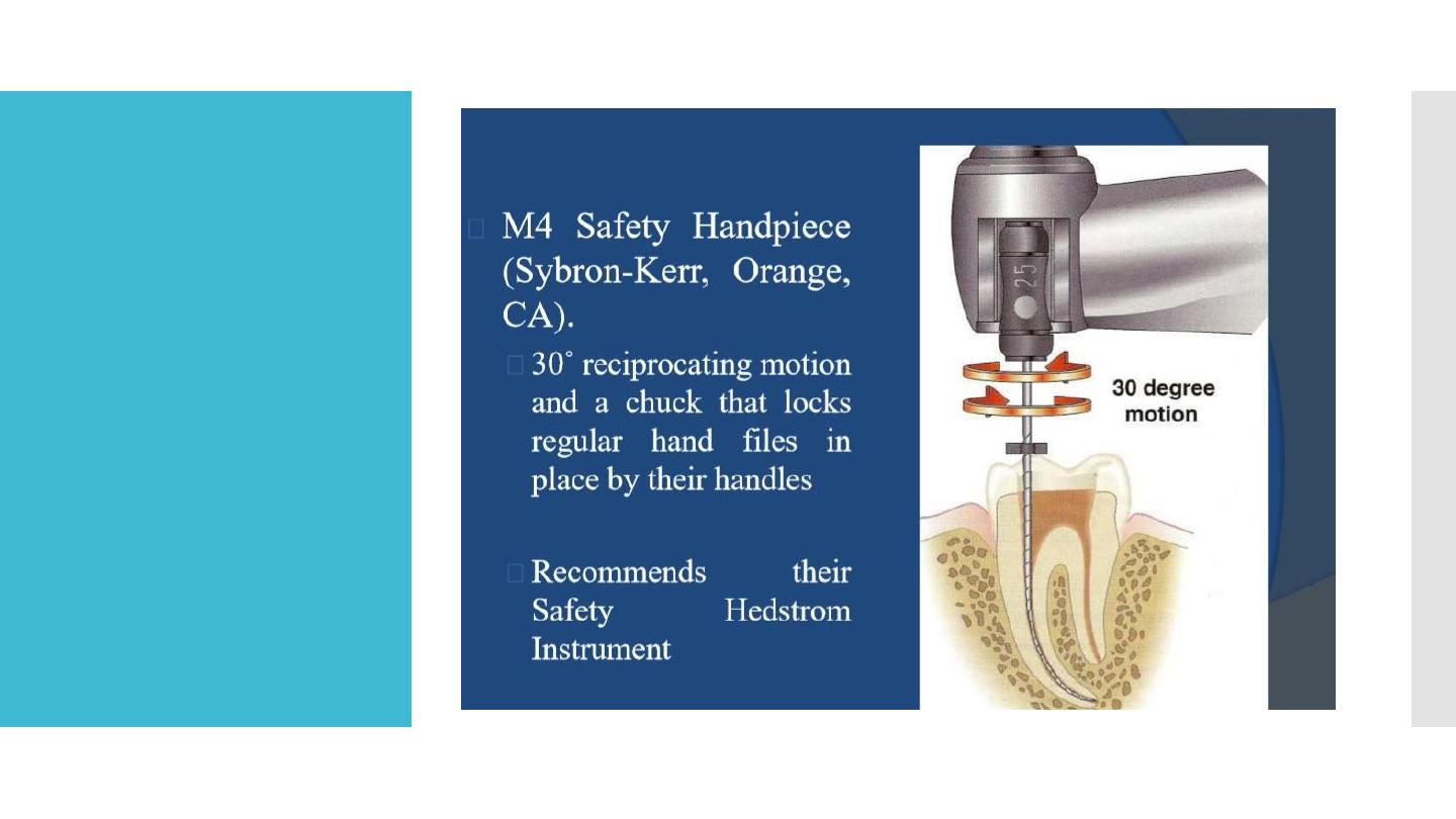
Engine-driven
reciprocating
instruments

From Stainless
Steel to Nickel
Titanium
Stainless steel
stiffness
Inherent in the material used, stainless steel files have a
high stiffness that increases with increasing instrument
size and causes high lateral forces in curved canals
These restoring forces attempt to return the instrument to
its original shape and act on the canal wall during
preparation, influencing the amount of dentin removed.
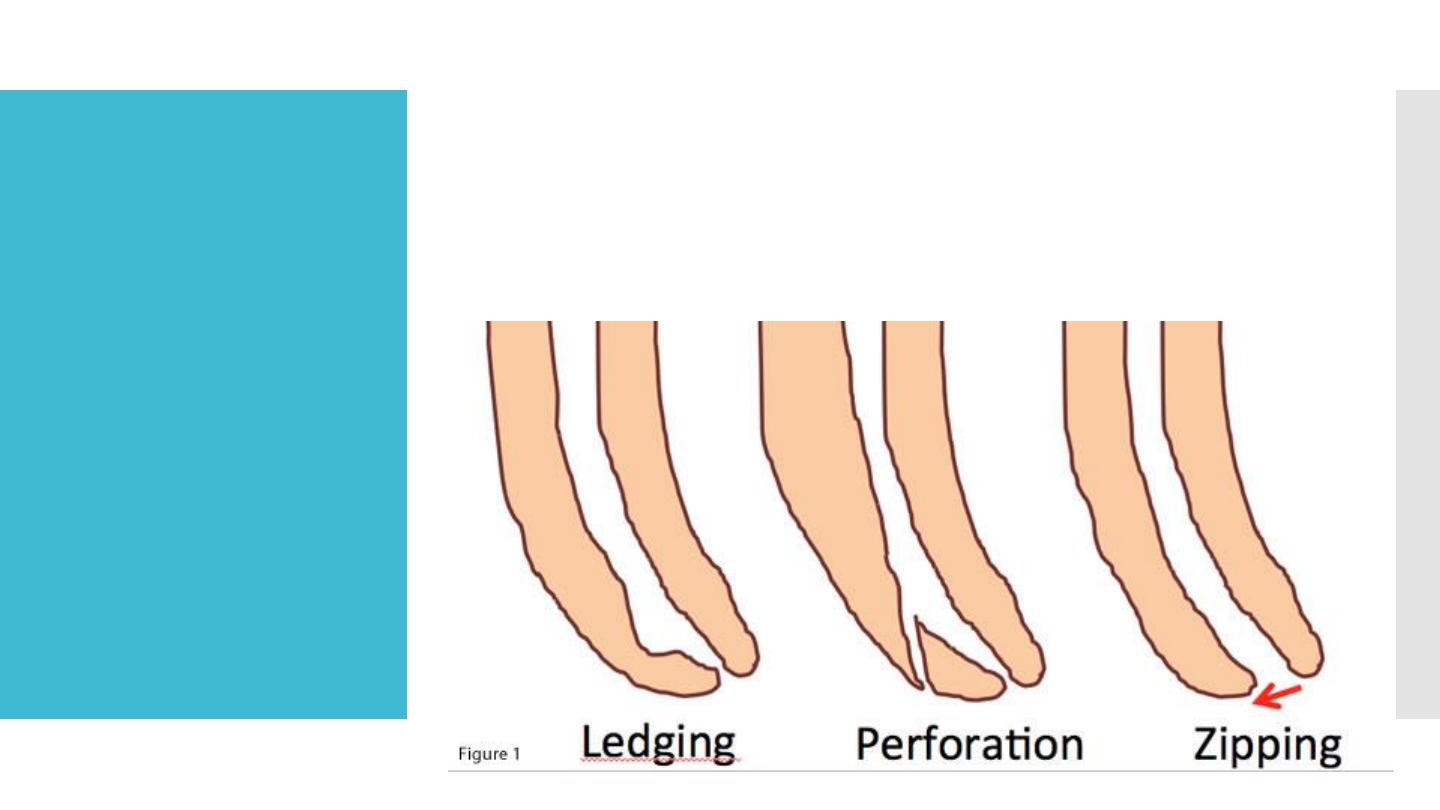
Resulting
transportation and canal aberrations (including
ledges, zippings and perforations) leave a
significant portion of the canal wall un-
instrumented, along with the creation of an
irregular cross-sectional shape that is harder to
obturat

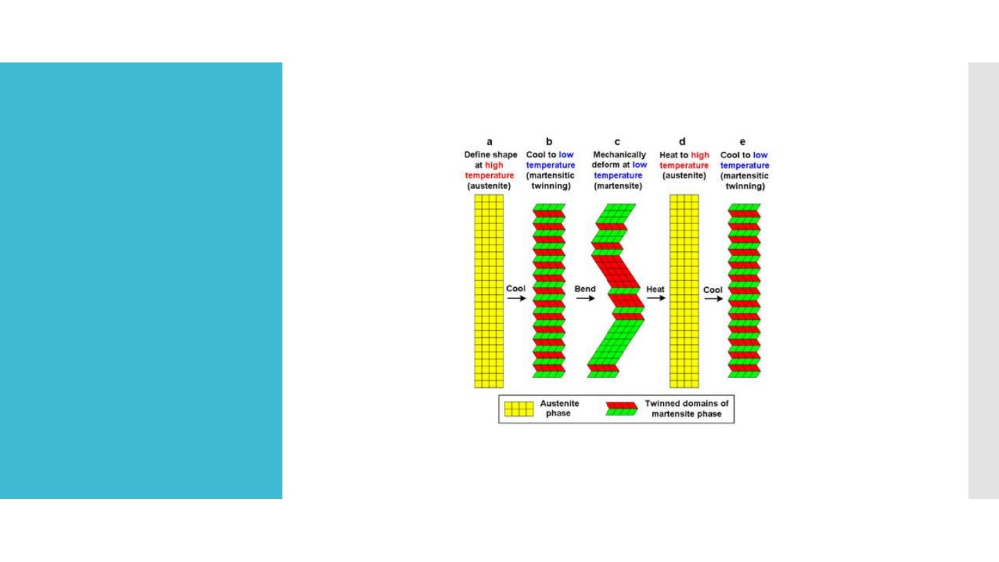
“shape
memory
alloys”
NiTi behaves like two different metals, as it may
exist in one of two crystalline forms. The alloy
normally exists in an austenitic crystalline phase
that transforms to a martensitic structure on
stressing at a constant temperature. In this
martensitic phase only a light force is required
for bending. If the stress is released, the
structure recovers to an austenitic phase and its
original shape
“shape
memory
alloys”
Fracture in
rotary
instrumeny
torsion
flexural
mode
A crown-down approach is
recommended to reduce torsional
loads (and thus the risk of
fracture) by preventing a large
portion instrument from engaging
root dentin (known as taper lock)
n of the tapered rotating
Rotary file

precaution
Avoid too much pressure is applied to the file. Never force a file!
These instruments require a passive technique.
If resistance is encountered, stop immediately, and before
continuing, increase the coronal taper and negotiate additional
length, using a smaller, 0.02 taper stainless steel hand tile.
A nickel-titanium instrument should not be used to bypass ledges.

Component of
endodontic
instrument
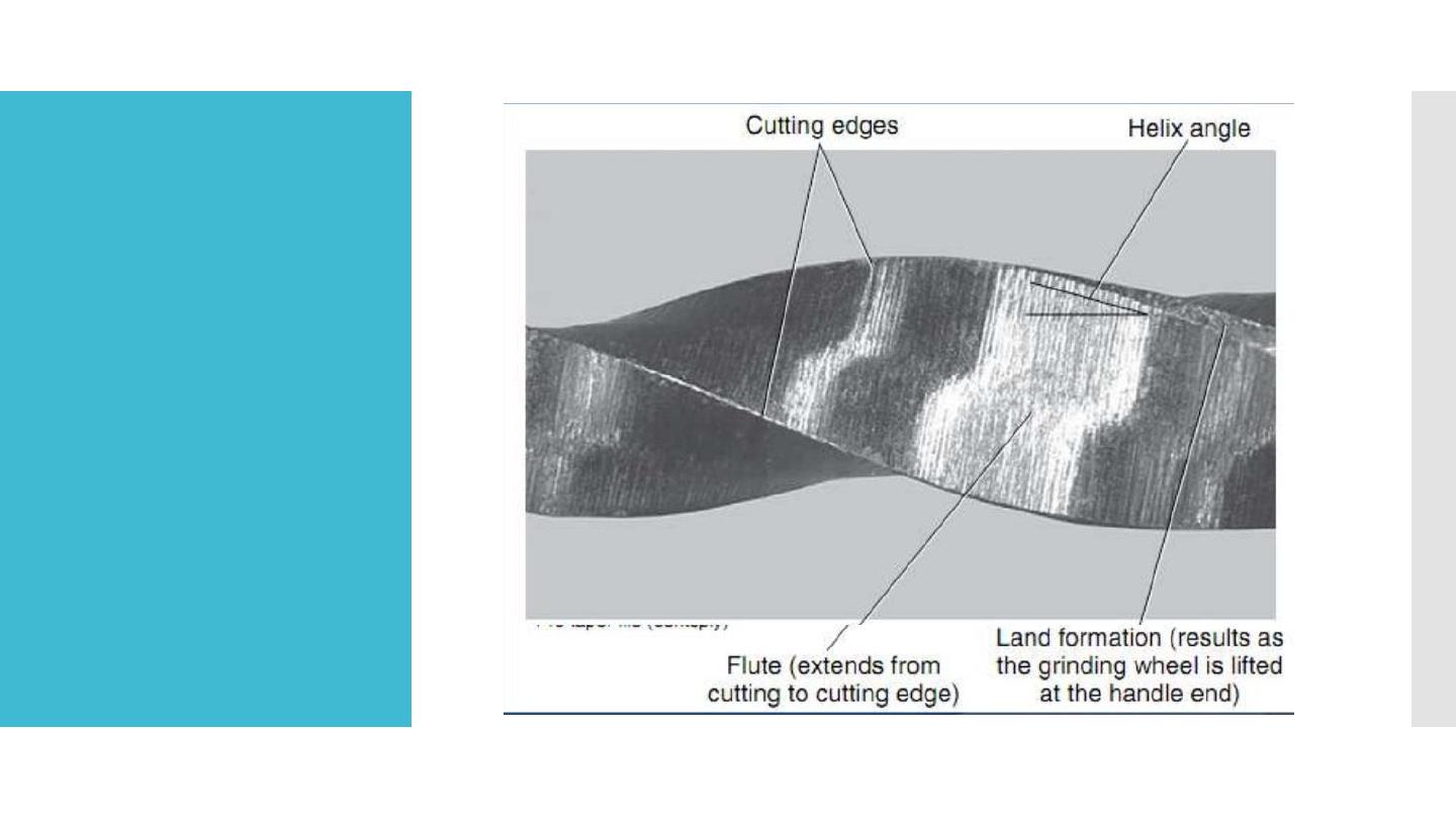
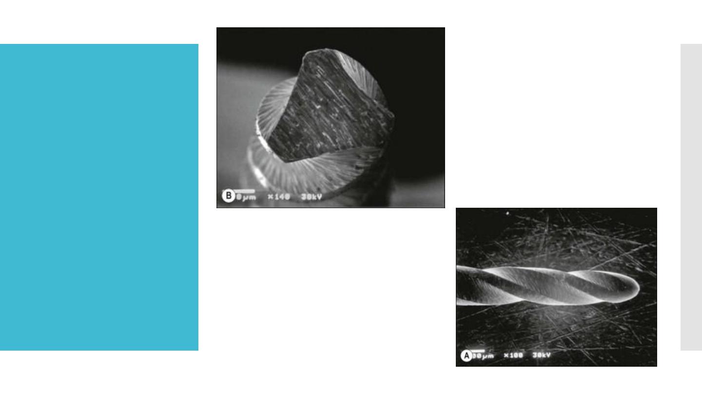
Flute:
Groove in the working surface used to collect soft
tissue and dentine chips removed from the canal
wall.
The effectiveness of the flute depends on its depth,
width, configuration, and surface finish.
Its effectiveness depends on its angle of incidence
and sharpness.

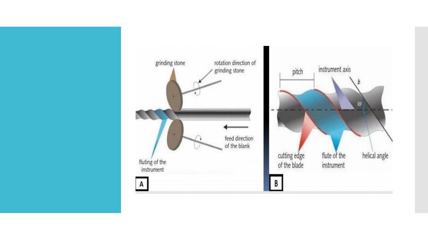
Flute
Flutes are grinding out a groove of specific profile in a cylindrical
or conical blanck NiTi.
Adjoining flutes creat a cutting blade.
Flutes are characterize by:
Depth of the flutting.
Pitch.
Helical angle
Confegration of flutting
Flute

Component of
endodontic
instrument
Radial land/ marginal width:
Is a flat cutting surface present between two grooves/
flutes.
The land touches the canal walls at the periphery of
the file and reduces the tendency of the file to screw
into the canal,
Reduces transportation of the canal.
Reduces the propagation of microcracks on its
circumference,
Supports the cutting edge, and Limits the depth of
cut.

Disadvantages:
Clogging of the instruments,
Friction and heat build-up,
Inefficient cutting.
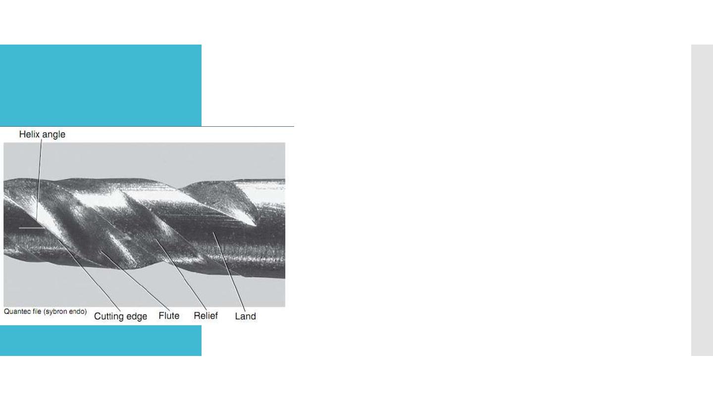
Relief:
Surface area of land that is reduced to a certain extent
to reduce frictional resistance
.
Helix angle:
The angle the cutting edge forms with the long axis of
the file. Augers debris collected in the flute from the
canal.
This angle is important for determining which file
technique to use.
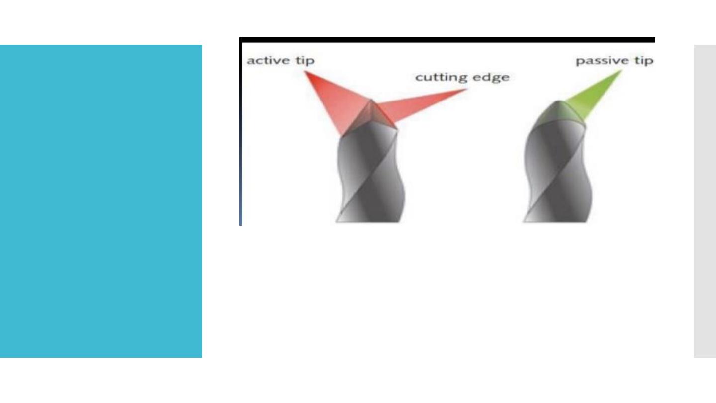
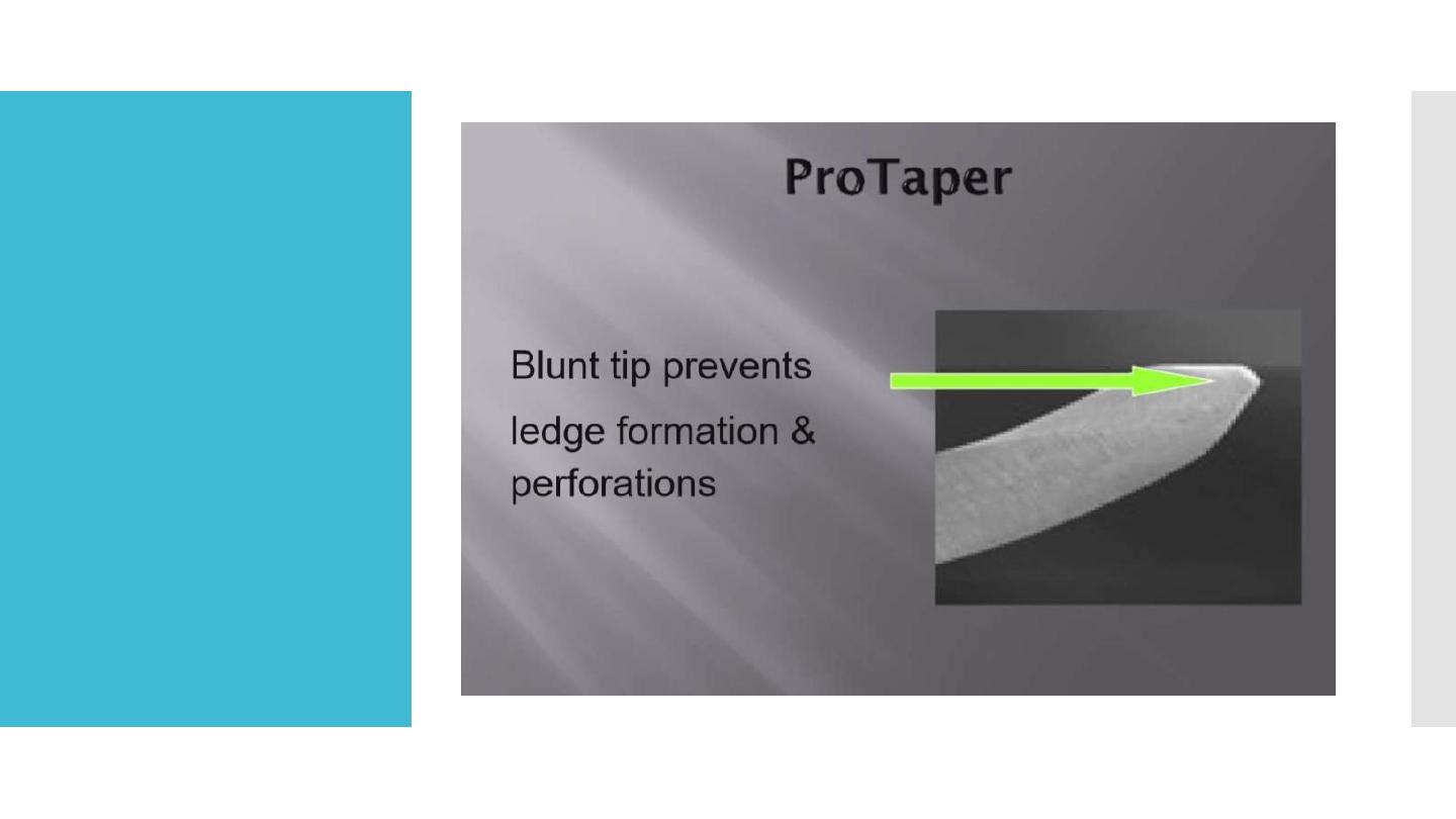
Tips
Is the element of the working part that perform the guiding
function, it is the first part that starts cutting through then the
blades will enlarge the canal wall.
The tipe might have sharp end ( active tip)
or blunt end( passive tip)
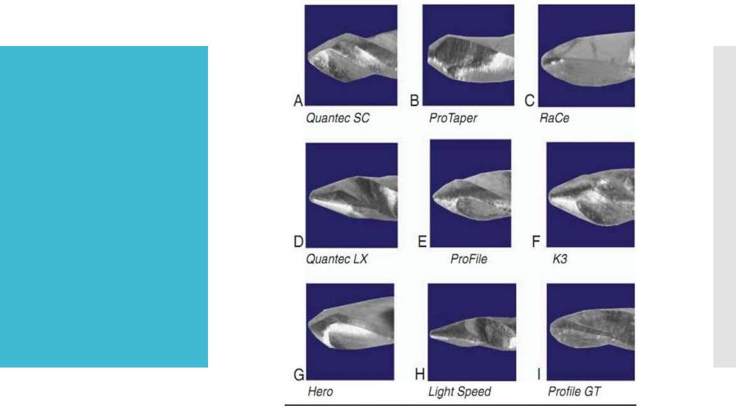
Tips

Tips
The passive tip reduce the deviation from the canal axis
Limits canal perforation of transportation or ledge
formation
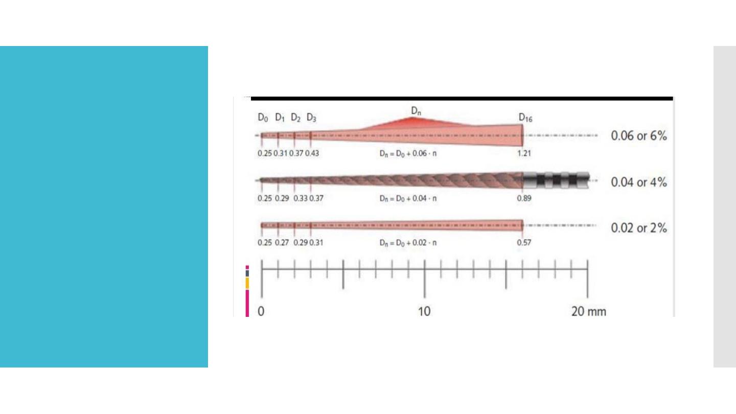
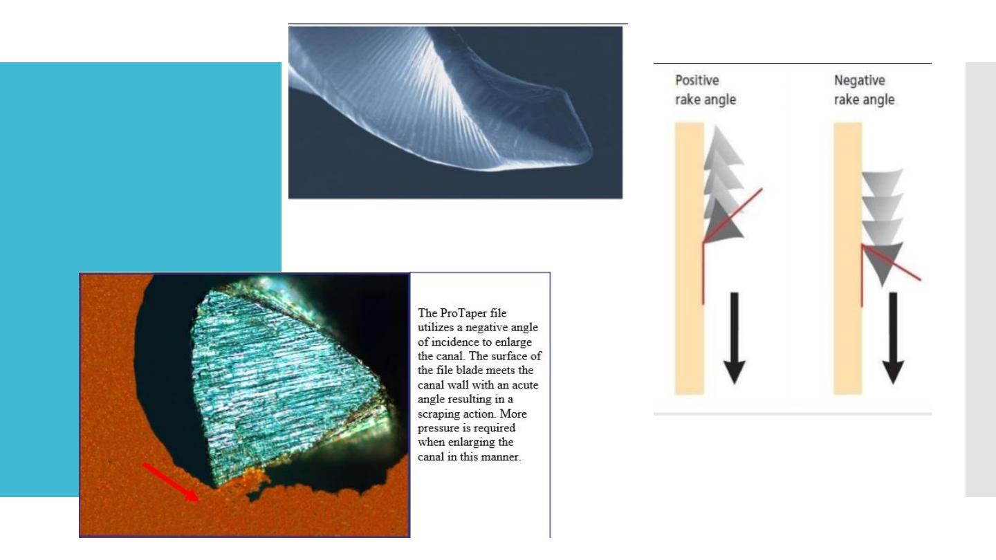
Tapering

Rake angle
If the file is sectioned perpendicular to its long axis, the
rake angle is the angle formed by the leading edge and
the radius of the file. If the angle formed by the leading
edge and the surface to be cut (its tangent) is obtuse,
the rake angle is said to be positive or cutting.
If the angle formed by the leading edge and the surface
to be cut is acute, the rake angle is said to be negative
or scraping
.
Rake angle

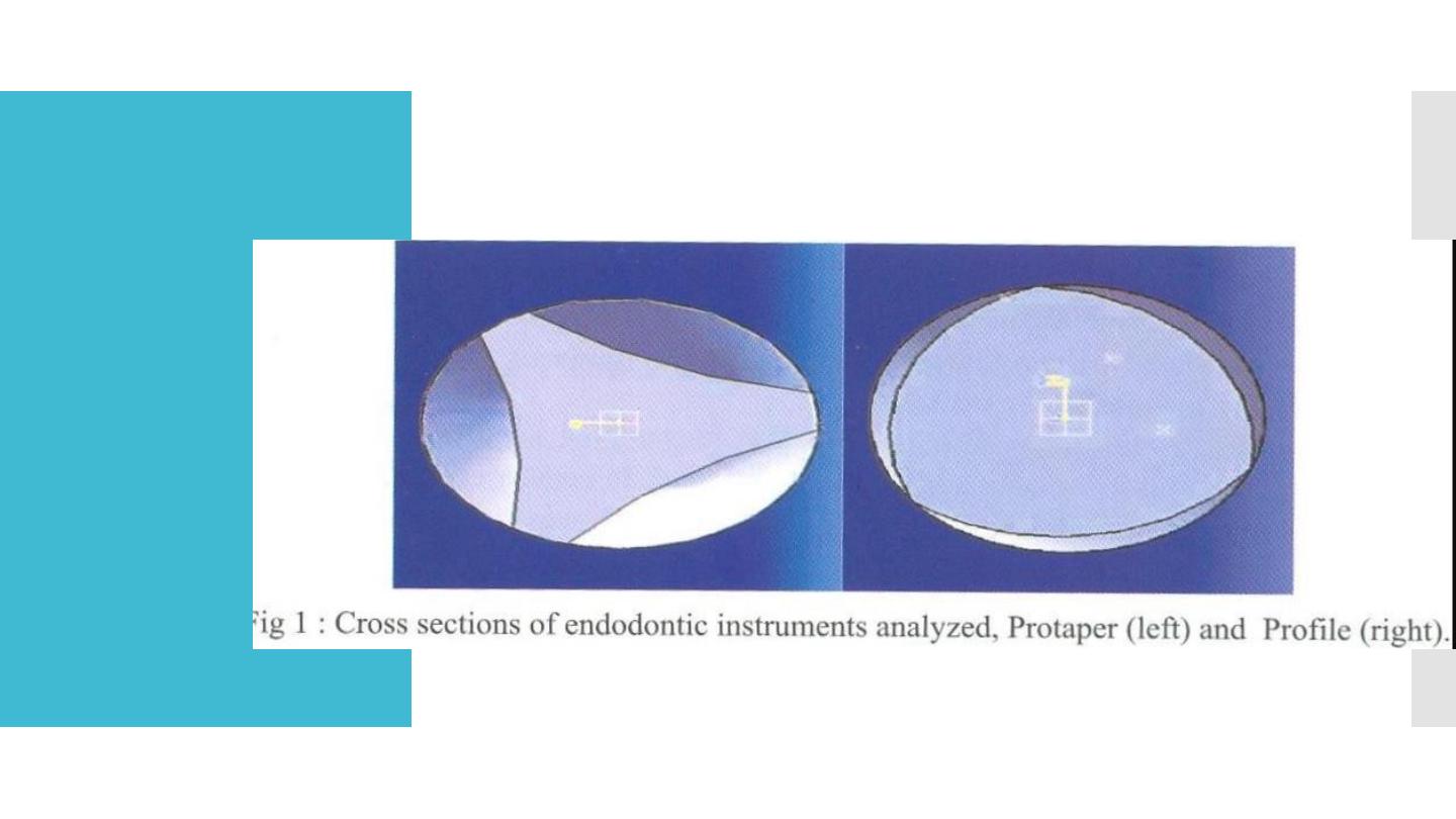
Non ISO
systems
Profile system
was introduce in 1994
Have increase tapering compared with conventional hand
instrument.
The tips of the profile series 29 rotary instrument had a constant
proportion of diameter increment (29%).
The constant percentage increase offers a smooth, progressive
enlargement of the canal. They're also designed with the same U
file flute and safety transition angle as our Profile ISO files.
Radial lands and parallel central core to increase the flexibility
Lateral views show a 20 degres helix angle, constant pitch, bulet
shaped non cutting tips and with slight negative rake angle.
This configuration facilitates a reaming action.
Debris is transported coronally and effectively from the root canals
The prefered speed 275-325 rpm
Profile system
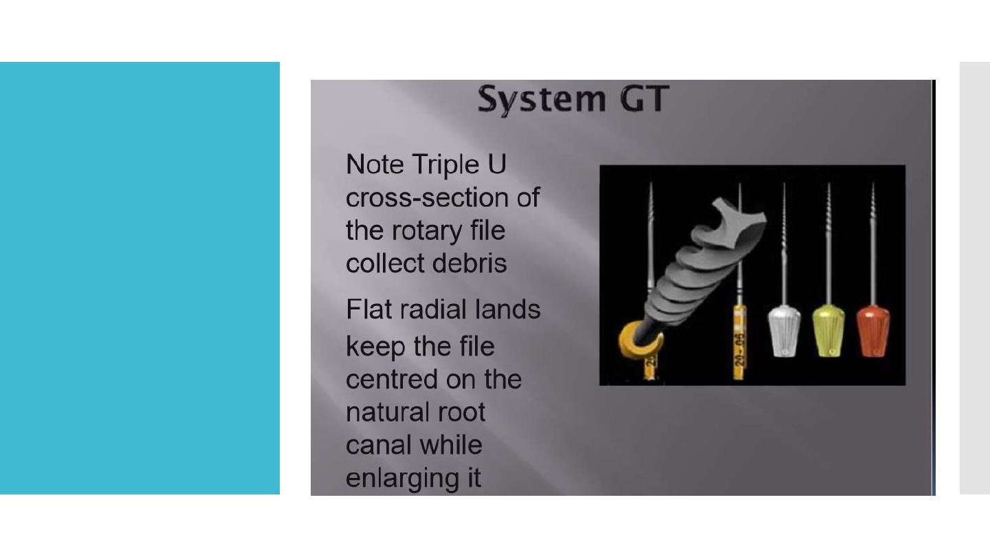
Profile GT files

Profile
GT
Greater tapering
Comes in four tapering
0.06, 0.08, 0.10 and 0.12
Maximum diameter of working part coronally 1mm
Have variable pitch and increasing number of flutes in
progression to the tip.
The apical instrument diameter is 0.2mm
The instrument tips are non cutting and round
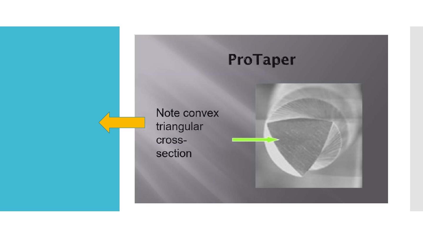
ProTaper
universal
system
Reduces the
contact area
between the
file and dentin
Compere
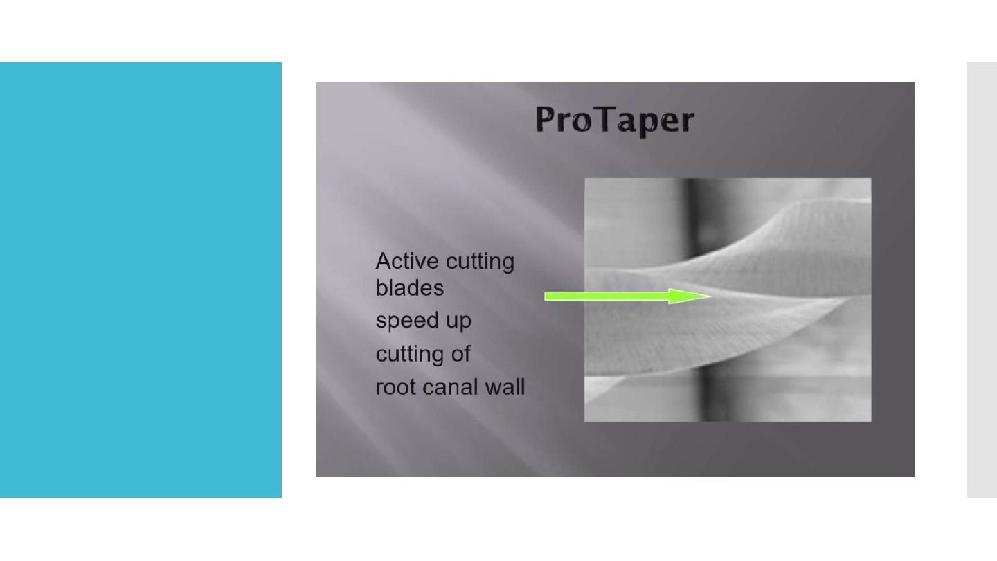
Shows
modified K-
type file with
sharp cutting
edges and no
radial lands
Protaper
stable core and
flexible for
smaller files
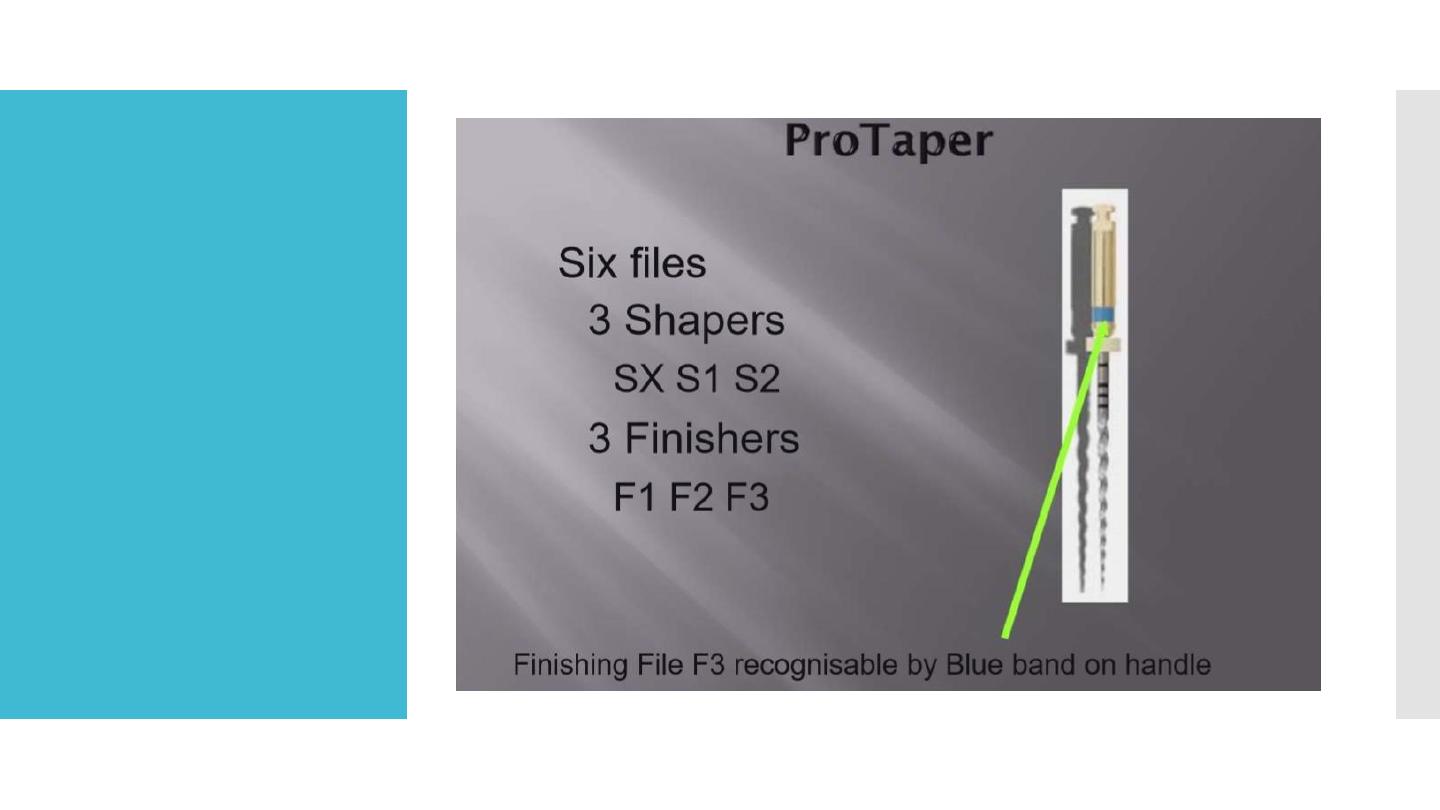
3 shapping
3 finishing

ProTaper
Universal
system
The set is increased by 2 larger finishing
file
The 3 finishing files and a set designed for
retreatment procedure.
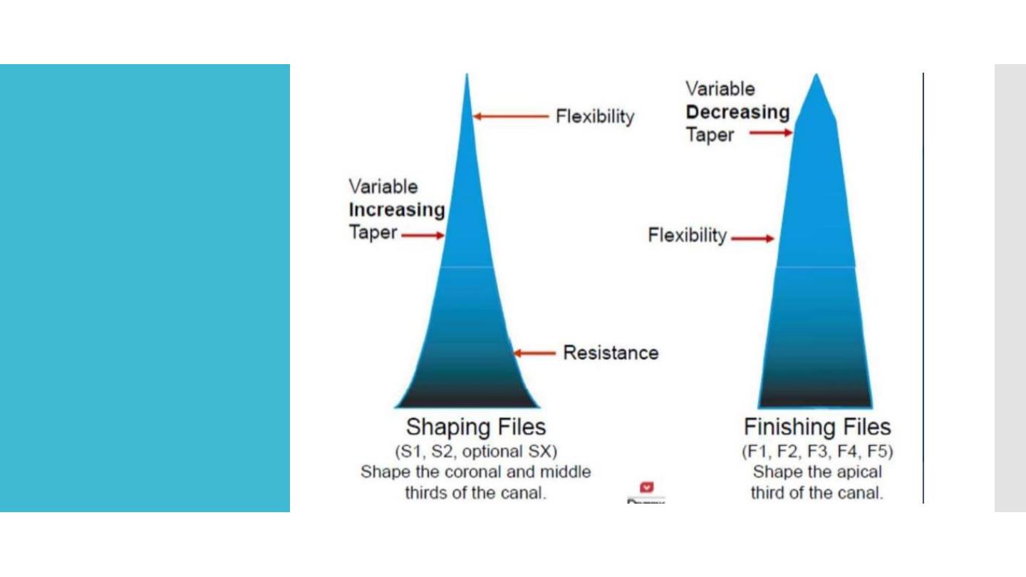
Varies tapering for this system along the
long axes.
The 3 shaping files have taper increase
coronally, and the reverse pattern is seen
in the fifth finishing file.
The difference
between

Smart taper
name
Diameter @ tip
Diameter @ D no.
S1
0.18
@D14=1.2
S2
0.2
@D14=1.1
F1-F2-F3-F4&F5
0.2,0.25,0.3,0.4&0.
5
@D3=0.07,0.08,0.0
9,0.05,0.04
Fishing file tips are rounded non cutting end

Recommended
for the
ProTaper
Preparation of glide path
The use of lateral brushing working stroke. Such a
stroke allows the clinician to direct larger files coronally
a way from danger zones and counteract any
“threading-in” effect
.

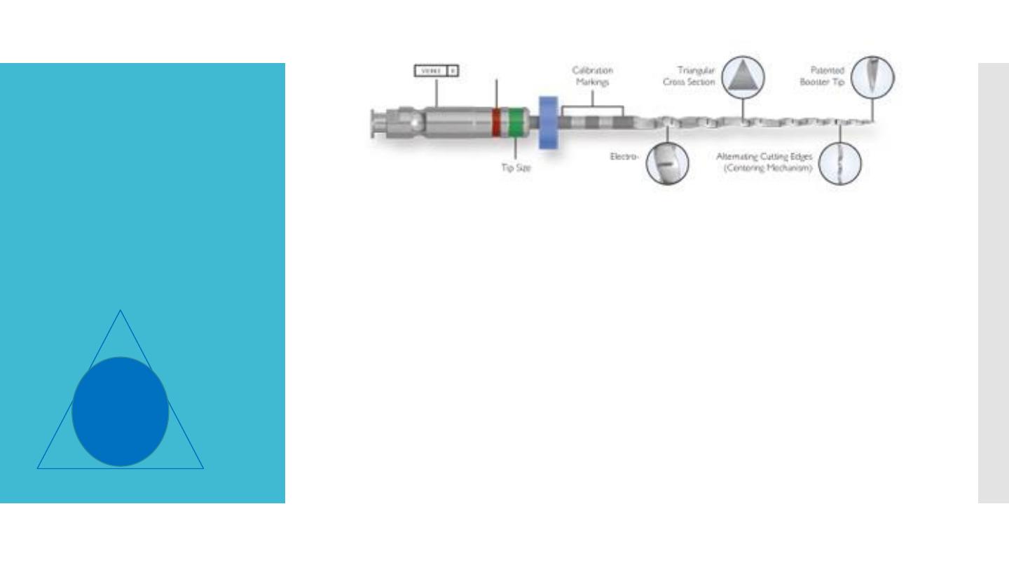
RaCe, Bio Race
The RaCe was manufactured since 1999 by FKG.
The name stands for remear with ulternating cutting
edges. This design aimed at reducing the tendency to
thread the file into the root canal.
Cross sections are triangular or square for #02
instruments with size #15 and #20 tips.
The surface quality of RaCe instrument is done by
electropolishing.
The tips are round and non cutting
RaCe endofile
Alternating cutting edges
The exclusive patented file design avoids screwing-in
effect and allows a better control of the instrument’s
progression
1- Sharp edges for an optimum cutting.
2- Thin core for increased flexibility.
3- More space for debris removal

RaCe
Optimal cutting efficiency Triangular cross-section
with sharp edges Cuts better and faster, without any
pressure
(1) The smaller core grants a higher flexibility
(2) and allows a better progression in curved canals
More space for debris removal
(3), improving debris evacuation to avoid instrument
blocking

RaCe
Exclusive rounded safety tip* Perfect centering of the
instrument in the canal Bypasses irregularities and
avoids lateral canals Less risk of perforations and
ledges *Except for D-Race first instrument (DR1) which
has an active tip.
Electrochemical polishing Enhanced resistance against
fatigue and corrosion The treatment eliminates surface
imperfections, reducing drastically the risk of weak
points (micro-cracks) The resulting shiny surface allows
better cleaning and disinfection, improving the
sterilization process

Twisted file
In 2008, SybronEndo presented the first fluted NiTi file.
Manufactured by plastic deformation, a process similar to the
twisting process that is used to produce stainless steel K-files.
According to the manufacturer, a thermal process allows twisting
during a phase transformation into the so called R-phase of nickel-
titanium.
The instrument is currently available with size #25 tip sizes only,
in taper .04 up to .12.
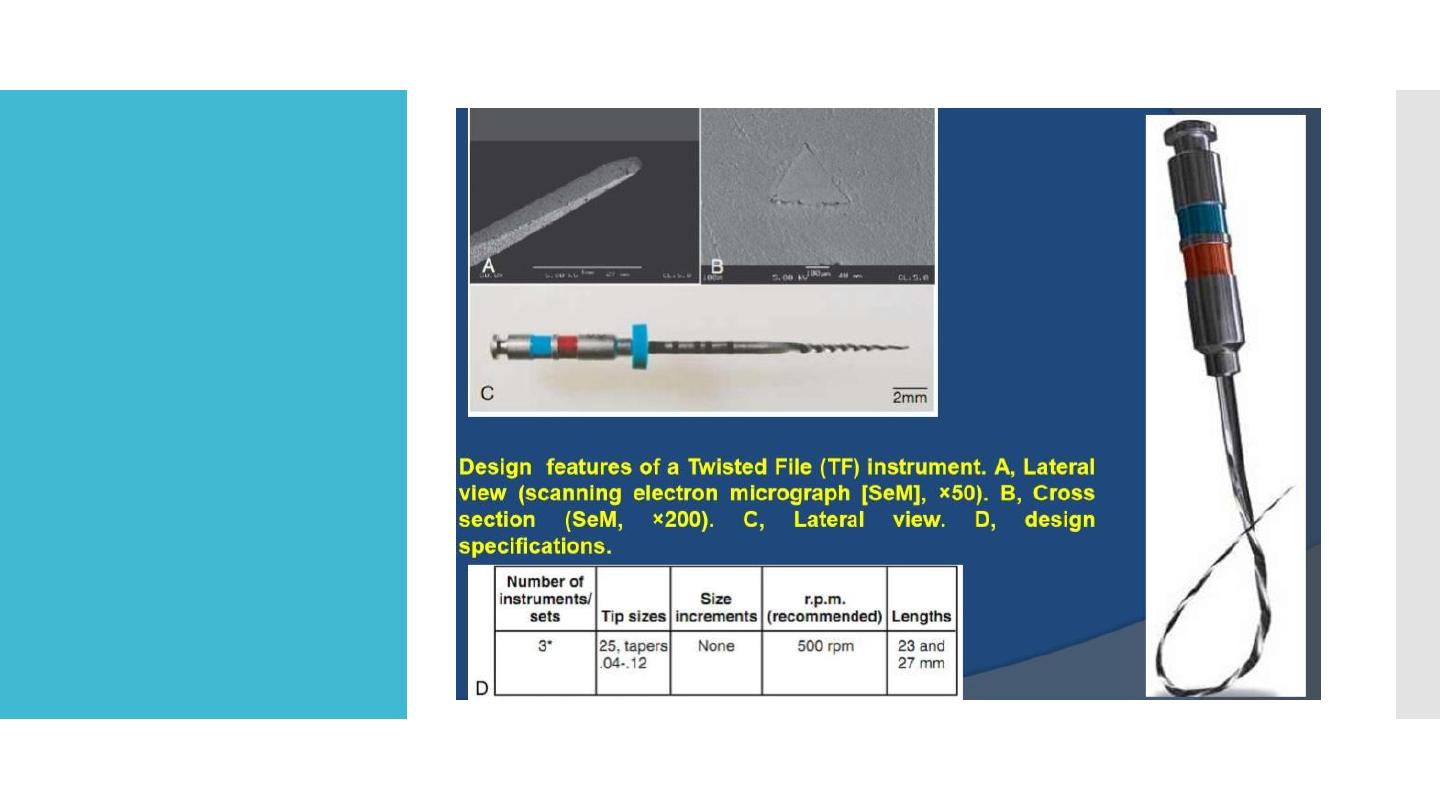
Twisted file

Twisted file
Twisted Files size #25 .06 taper were more flexible
than ProFiles of the same size.
The manufacturer recommends a conventional
crown-down technique after securing a glide path
with a size #15 K-file.
Specifically, for a “large” canal, tapers .10 to .06
should be used, and in a “small” canal, tapers .08 to
.04 are recommended.

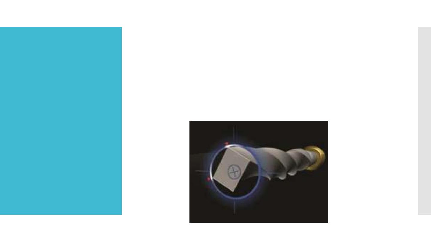
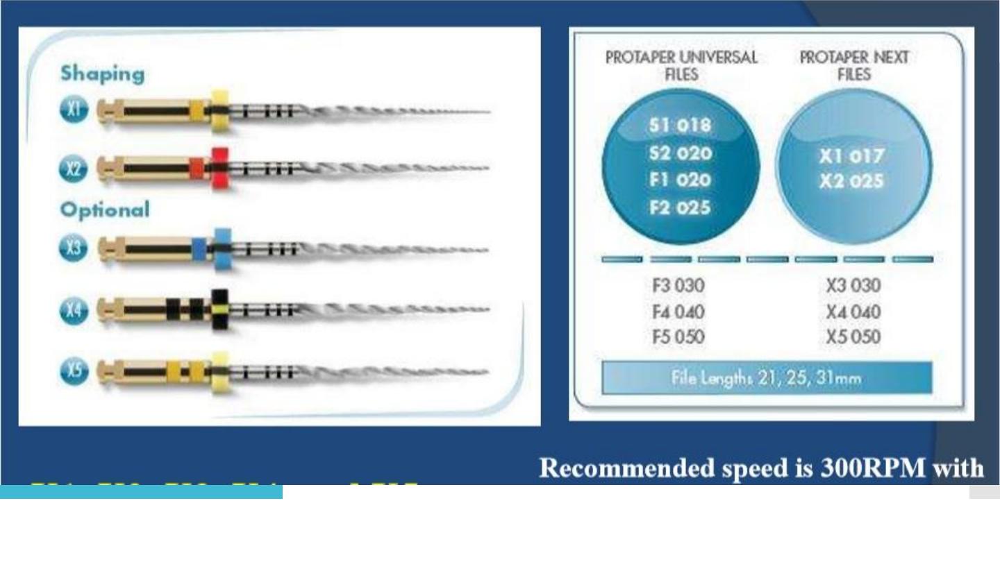
ProTaper Next
Protaper Next
The convergence of a variable tapered design on a given file
(ProTaper Universal), innovative MWire technology, and a unique
offset mass of rotation.
Off-centred, rectangular cross section giving the files a unique,
snake-like swaggering movement.
This improved action creates an enlarged space for debris
removal, optimizes the canal tracking and reduces binding.
X1, X2, X3, X4, and X5
Corresponding to sizes: 17/04, 25/06, 30/07, 40/06, and 50/06,
respectively.
Recommended speed is 300RPM with a
ProTaper Next
M-Wire technology: Improves the resistance to
cyclic fatigue by almost 400% when comparing files
of the same tip diameter, taper and cross-section.
Offset mass of rotation: Asymmetrical rotary
motion and, at any given crosssection, the file only
contacts the wall at 2 points.
X1, X2, X3, X4, and X5
Corresponding to sizes: 17/04, 25/06, 30/07, 40/06, and 50/06, respectively

PTNext
Clinically, this provides 3 significant advantages:
Reduced engagement due to the swaggering effect
which limits undesirable taper lock.
Affords more cross-sectional space for enhanced
cutting, loading, and augering debris.
Allows any PTN file to cut a bigger envelope of
motion compared to a similarly-sized file with a
symmetrical mass and axis of rotation.
This means a smaller-sized and more flexible PTN
file can cut the same-size preparation as a larger and
stiffer file with a centered mass and axis of rotation.

Wave one file
The WaveOne single-file reciprocating system
Single-use, Single-file system to shape the root canal
completely from start to finish.
M-Wire technology.
Improving strength and resistance to cyclic fatigue by
up to nearly four times in comparison with other rotary
NiTi files.
At present, there are three files in the WaveOne single-
file reciprocating system available in lengths of 21, 25
and 31 mm
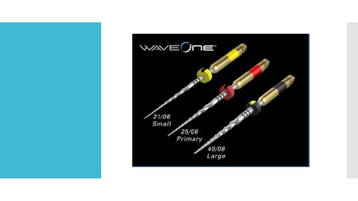
Wave one file

Wave one file
The WaveOne Small file is used in fine canals. The tip
size is ISO 21 with a continuous taper of 6 %.
The WaveOne Primary file is used in the majority of
anals. The tip size is ISO 25 with an apical taper of 8
% that reduces towards the coronal end.
The WaveOne Large file is used in large canals. The
tip size is ISO 40 with an apical taper of 8 % that
reduces towards the coronal end
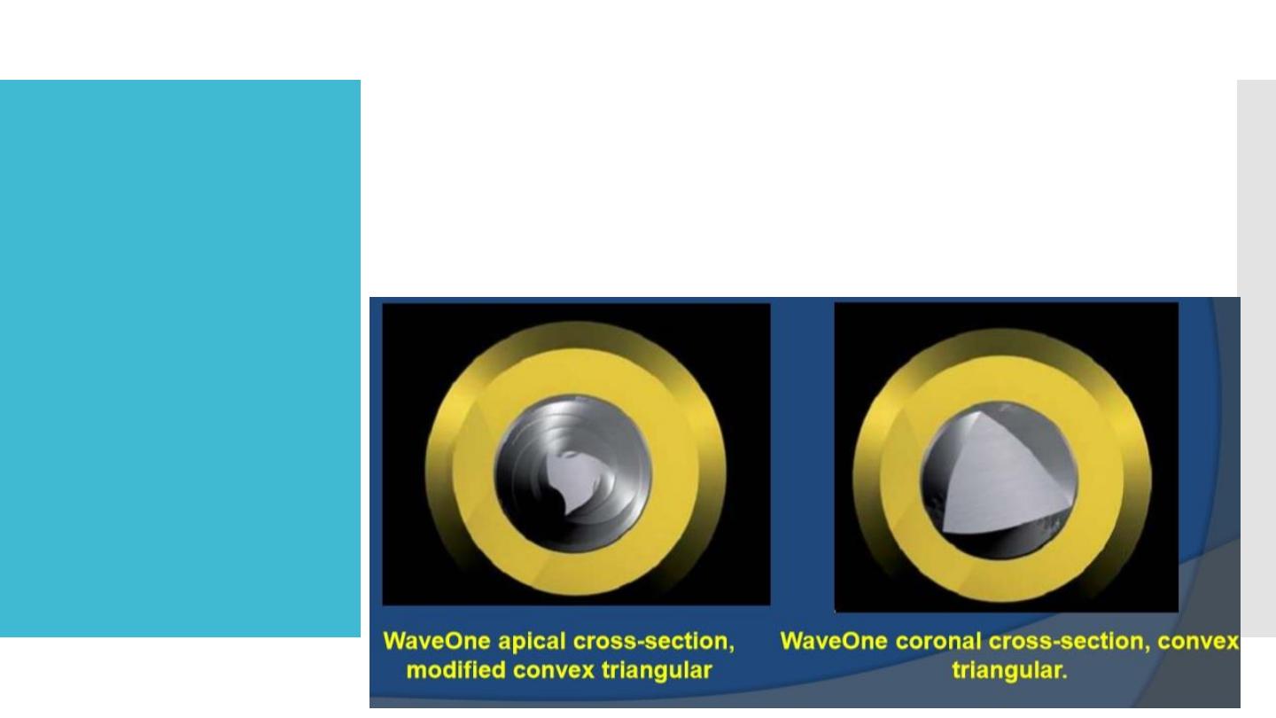
Wave one file
The instruments are designed to work with a reverse
cutting action.
All instruments have a modified convex triangular
crosssection at the tip end, and a convex triangular
cross-section at the coronal end . This design
improves instrument flexibility overall

Wave one file
The specially designed NiTi files work in a similar but
reverse “balanced force” action using a
preprogrammed motor to move the files in a back and
forth “reciprocal motion”
The counter-clockwise (CCW) movement is greater
than the clock-wise (CW) movement. CCW movement
advances the instrument, engaging and cutting the
dentine.
CW movement disengages the instrument from the
dentine before it can (taper) lock into the canal.
Three reciprocating cycles complete one complete
reverse rotation and the instrument gradually advances
into the canal with little apical pressure required.
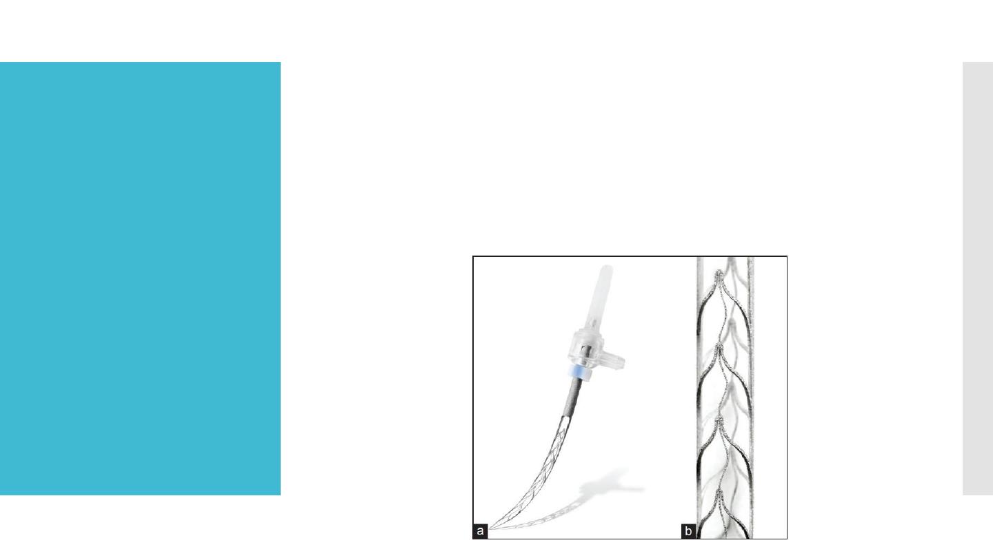
Self-adjusting
file
The instrument is made as a hollow, thin NiTi lattice
cylinder that is compressed when inserted into the
root canal and adapts to the canal’s cross-section.
It is attached to a vibrating handpiece.
Continuous irrigation is applied through a special
hub on the side of its shank.
Self-adjusting
file
The SAF instrument adapted into a root canal that was
initially prepared with #20 K-file.
Right: A#20 K-file in the canal.
Left: The SAF file in its relaxed form.
Center: The SAF file inserted into the same narrow canal.
It will apply delicate pressure on the canal wall,
attempting to resume its original shape.

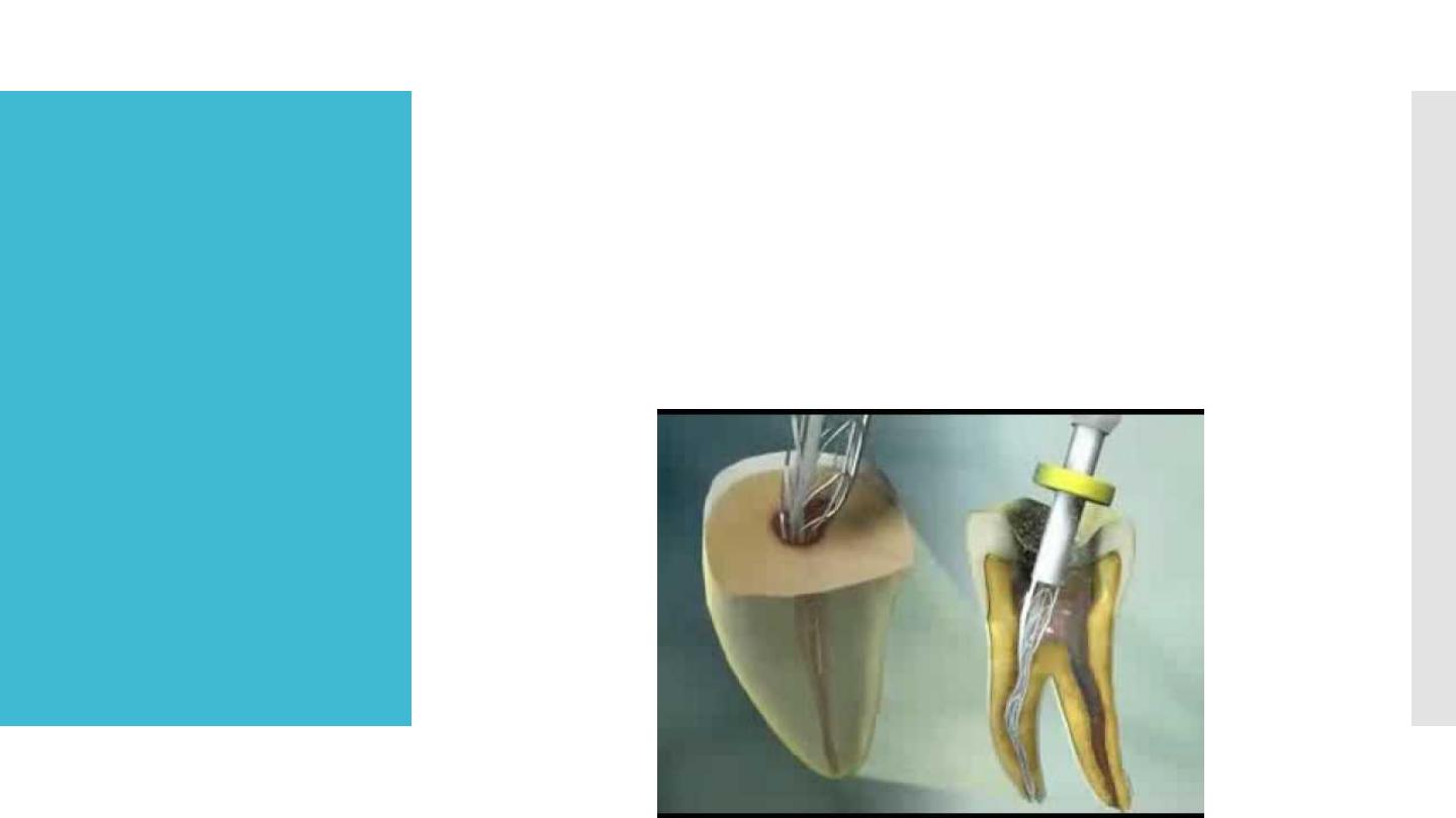
Self-adjusting
file
The abrasive surface and details of the lattice of the
SAFinstrument.
The extreme elasticity is the total of the elasticity of
each of the delicate NiTi segments
.
During operating requirements are:
continuous irrigation unit used with the SAF
instrument.
The unit has two containers and provides a
continuous flow (low pressure, 5 ml/min) of either
irrigant (i.e., sodium hypo-chlorite and edTA)
through double silicon tubes that are connected to
the hubs on the front of the device.
It is controlled by finger-operated switches located
on the handpiece

Thank you