
1
Designation: C 187
American Association State Highway and Transportation Officials Standard AASHTO No.: T 129
Standard Test Method for
Normal Consistency of
Hydraulic Cement
1
1. Scope
This test method covers the determination of the normal consistency of
hydraulic cement.
2. Significance and Use
This test method is intended to be used to determine the amount of water
required to prepare hydraulic cement pastes for testing.
3. Apparatus
3.1 Weights and Weighing Devices—The weights and weighing devices
shall conform to the requirements of Specification C 1005. The weighing
device shall be evaluated for precision at a total load of 1000 g.
3.2 Glass Graduates, 200 or 250-mL capacity, and conforming to the
requirements of Practice C 490.
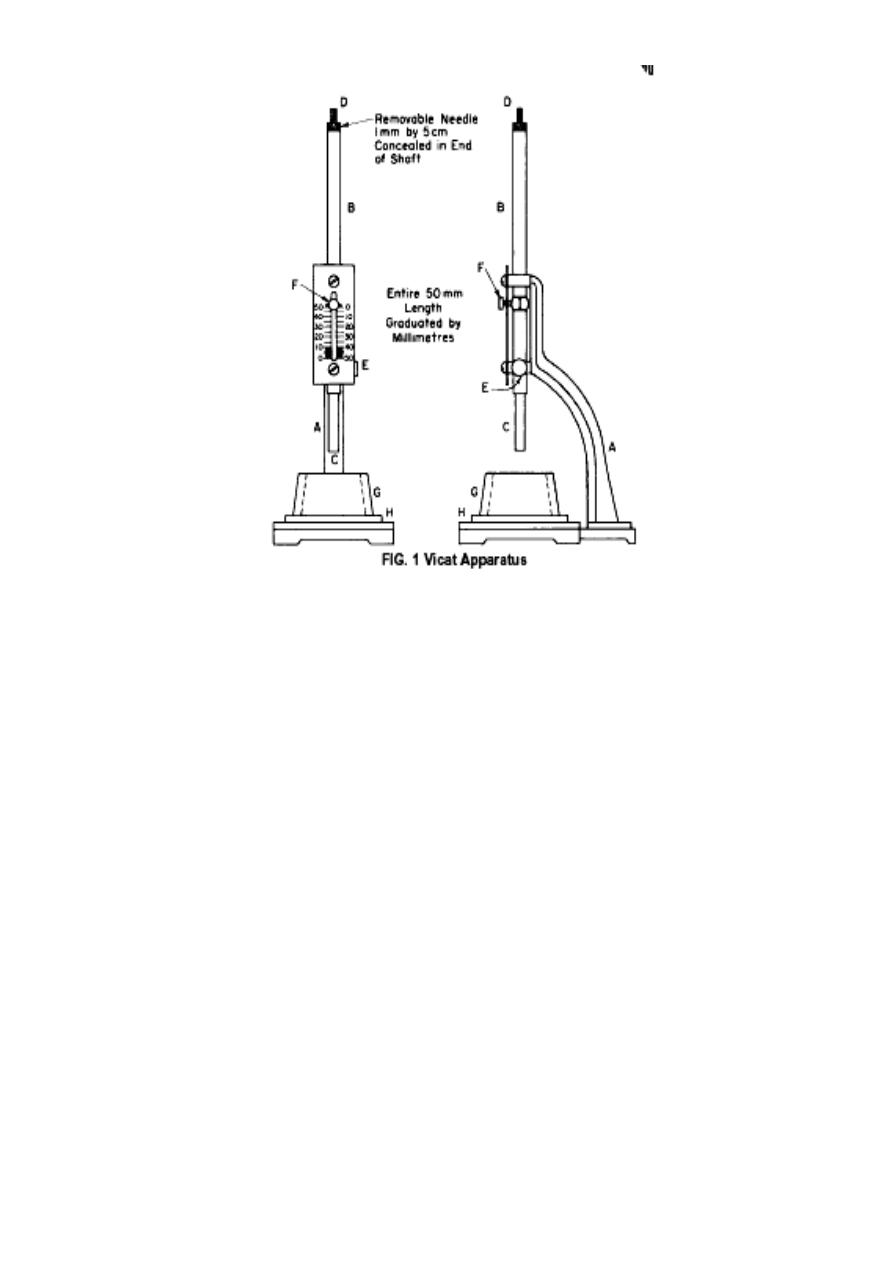
3.3 Vicat Apparatus—The Vicat apparatus shall consist of a frame A (Fig.
1) bearing a movable rod B, weighing 300 g, one end C, the plunger end,
being 10 mm in diameter for a distance of at least 50 mm, and the other
end having a removable needle D, 1 mm in diameter and 50 mm in
length. The rod B is reversible, and can be held in any desired position by
a set screw E, and has an adjustable indicator F, which moves over a
scale (graduated in millimeters) attached to the frame A. The paste is held
in a rigid conical ring G, resting on a plane no absorptive square base
plate H, about 100 mm on each side. The rod B shall be made of stainless
steel having a hardness of not less than 35 HRC, and shall be straight
with the plunger end which is perpendicular to the rod axis. The ring shall
be made of a noncorroding, nonabsorbent material, and shall have an
inside diameter of 70 mm at the base and 60 mm at the top, and a height
of 40 mm. In addition to the above, the Vicat apparatus shall conform to
the following requirements:
Diameter of needle 1 mm
Inside diameter of ring at bottom 70 mm.
Inside diameter of ring at top 60 mm.
Height of ring 40 mm
3.4trowel- having a steel blade 100 to 150mm in length, with straight
edges.
3.5 plastic gloves
2
4. Temperature and Humidity
4.1 The temperature of the air in the vicinity of the mixing slab, the dry
cement, molds, and base plates shall be maintained between 20 and
27.5°C (68 and 81.5°F). The temperature of the mixing water shall not
vary from 23.0°C (73.5°F) by more than
6
2.0°C (3.5°F).
4.2 The relative humidity of the laboratory shall be not less than 50 %.
5. Procedure
5.1 Preparation of Cement Paste—Mix 650 g of cement with a measured
quantity of water following the procedure prescribed in the Procedure for
Mixing Pastes of Practice C 305.
5.2 Molding Test Specimen—Quickly form the cement paste, into the
approximate shape of a ball with gloved hands. Then toss six times
through a free path of about 150 mm (6 in.) from one hand to another so
as to produce a nearly spherical mass that may be easily inserted into the
Vicat ring with a minimum amount of additional manipulation. Press the
ball, resting in the palm of one hand, into the larger end of the conical
ring G, Fig. 1, Place the ring on its larger end on the base plate H, and the
smaller end at the top of the ring and smooth the top, During these
operations of cutting and smoothing, take care not to compress the paste.
5.3 Consistency Determination—Center the paste confined in the ring,
resting on the plate, under the rod B, Fig. 1, the plunger end C of which
shall be brought in contact with the surface of the paste, and tighten the

3
set-screw E. Then set the movable indicator F to the upper zero mark of
the scale, or take an initial reading, and release the rod immediately. This
must not exceed 30 s after completion of mixing. The apparatus shall be
free of all vibrations during the test. The paste shall be of normal
consistency when the rod settles to a point 10 ± 1 mm below the original
surface in 30 s after being released. Make trial pastes with varying
percentages of water until the normal consistency is obtained. Make each
trial with fresh cement.
6. Calculation
Calculate the amount of water required for normal consistency

4
Designation: C 191
Standard Test Method for Time of Setting of Hydraulic Cement by
Vicat Needle1
1. Scope
This method covers determination of the time of setting of hydraulic
cement by means of the Vicat needle.
2. Apparatus
2.1 Scales.
2.2 Weights.
2.3 Glass Graduates, 200 or 250-mL capacity, and conforming to the
requirements of Specification C 490.
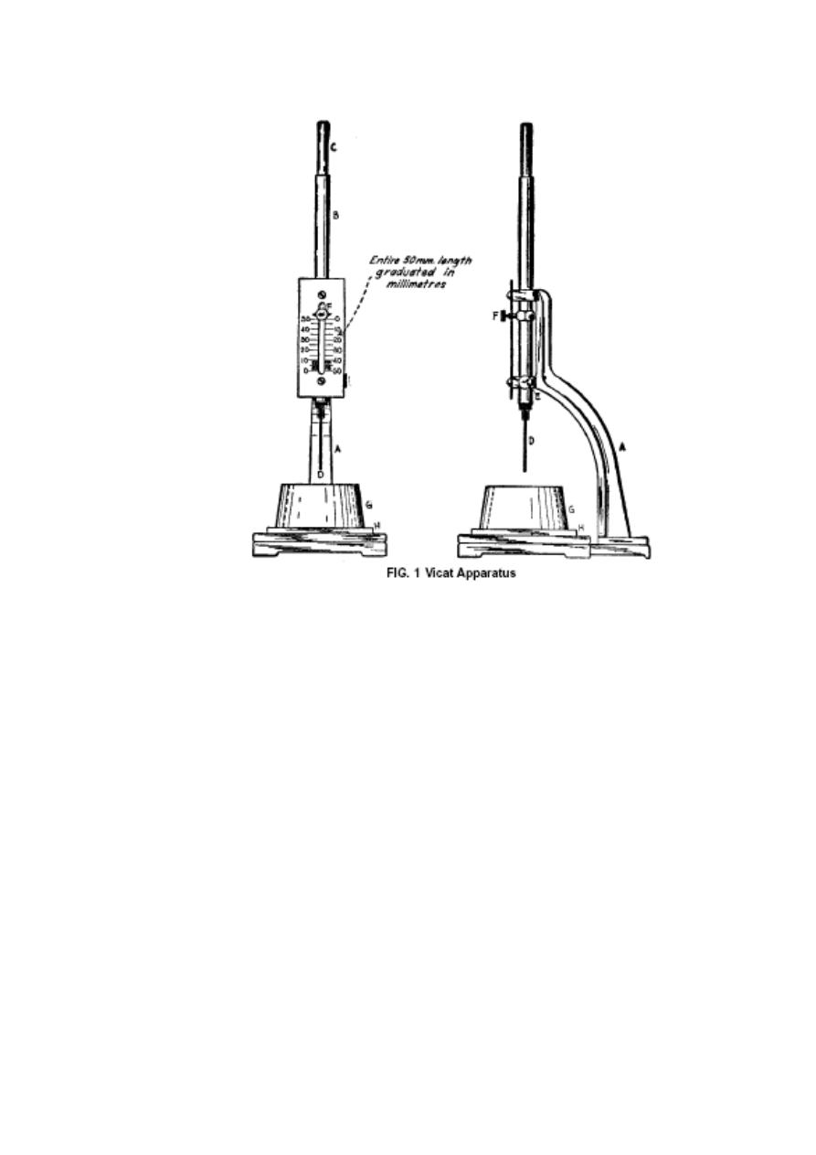
2.4 Vicat Apparatus—The Vicat apparatus shall consist of a frame, A,
Fig. 1, bearing a movable rod, B, weighing 300 g, one end, C, the plunger
end, being 10 mm in diameter for a distance of at least 50 mm and the
other end having a removable steel needle, D, 1 mm in diameter and 50
mm in length. The rod B is reversible, and can be held in any desired
position by a set screw, E, and has an adjustable indicator, F which
moves over a scale (graduated in millimetres) attached to the frame A.
The paste is held in a conical ring G, resting on a plate of similar
planeness, and absorptivity to that of glass H, about 100 mm square. The
ring shall be made of a noncorroding, nonabsorbing material, and shall
have an inside diameter of 70 mm at the base and 60 mm at the top and a
height of 40 mm. In addition to the above, the Vicat apparatus shall
conform to the following requirements:
Diameter of needle 1 mm
Inside diameter of ring at bottom 70 mm
Inside diameter of ring at top 60 mm
Height of ring 40 mm .
2.5 trowel having a steel blade 100 to 150 mm in length , with straight
edges.
2.6 plastic gloves.
2.7 pans , water , cement.
5
3. Temperature and Humidity
3.1 The temperature of the air, the dry cement, molds, and base plates
shall be maintained between 20 and 27.5°C.
3.2 The relative humidity of the laboratory shall be not less than 50 %.
3.3 The relative humidity of the laboratory shall be not less than 50 %.
The moist closet or moist room shall be so constructed as to provide
storage facilities for test specimens at a relative humidity of not less than
90 %.
4. Preparation of Cement Paste
Mix 650 g of cement with the percentage of mixing water required for
normal consistency Distilled water is preferable.
5. Procedure
5.1 Molding Test Specimen—Quickly form the cement paste, prepared as
described in the section on preparation of cement paste, into a ball with
the gloved hands and toss six times from one hand to the other,
maintaining the hands about 6 in. (150 mm) apart. Press the ball, resting
in the palm of the hand, into the larger end of the conical ring, G. Place
the ring on its larger end on a plate H and the smaller end at the top of

6
the ring and smooth the top by a sharp – edge trowel , during the
operation of cutting and smoothing, take care not to compress the paste.
Immediately after molding, place the test specimen in the moist closet or
moist room and allow it to remain there except when determinations of
time of setting are being made. The specimen shall remain in the conical
mold, supported by the plate of similar planeness, corrosivity, and
absorptivity to that of glass, H, throughout the test period. A time of set
specimen and an autoclave bar may be made from the same batch.
5.2 Time of Setting Determination— Allow the time of setting specimen
to remain in the moist cabinet for 30 min after molding without being
disturbed. Determine the penetration of the 1-mm needle at this time and
every 15 min thereafter until a penetration of 25 mm or less is obtained.
Note:- No penetration test shall be made closer than (6.4 mm) from any
previous penetration and no penetration test shall be made closer than
(9.5 mm) from the inside of the mold.
5.3 Precautions— Take care to keep the 1-mm needle straight, and the
needle must be kept clean as the collection of cement on the sides of the
needle may retard the penetration, while cement on the point may
increase the penetration.

7
Designation: C 1437 – 99
Standard Test Method for flow of Hydraulic Cement Mortar1
1. Scope
This test method covers the determination of flow of hydraulic cement
mortars.
2. Significance and Use
2.1 This test method is intended to be used to determine the flow of
hydraulic cement mortars, and of mortars containing cementitious
materials other than hydraulic cements.
2.2 While flow is not usually included in hydraulic cement specifications,
it is commonly used in standard tests that require the mortar to have a
water content that provides a specified flow level.
3. Apparatus
3.1 Flow Table, Flow Mold, Conforming to the requirements of
Specification C 230.
3.2 Caliper, Conforming to the requirements of Specification C 230.
3.3 Tamper, conforming to the requirements of Test Method C 109.
3.4 Trowel, having a steel blade 100 to 150 mm in length, with straight
edges.
3.5 Straightedge, made of steel, shall be at least 200 mm long and not less
than 1.5 mm nor more than 3.5 mm in thickness. Its edge shall not depart
from a plane surface by more than 1 mm .
4. Temperature and Humidity
The temperature of the air in the laboratory shall be maintained between
20 and 28°C and its relative humidity shall not be less than 50 %.
5. Materials
Hydraulic Cement Mortar—A mortar for which the determination of
flow is specified or desired.
6. Procedure
6.1 Determination of Flow:
6.1.1 Carefully wipe the flow table clean and dry, and place the flow
mold at the center. Place a layer of mortar about 25 mm in thickness in
the mold and tamp 20 times with the tamper. The tamping pressure shall
be just sufficient to ensure uniform filling of the mold. Then fill the mold
with mortar and tamp as specified for the first layer. Cut off the mortar to
a plane surface . Lift the mold away from the mortar 1 min after
completing the mixing operation. Immediately drop the table through a
height of 12.7±0.13 mm 25 times in 15 s, unless otherwise specified.

8
7. Calculation
7.1 The flow is the resulting increase in average base diameter of the
mortar mass, expressed as a percentage of the original base diameter.
7.2 If using the caliper specified in Specification C 230, add the four
readings, and record the total. This gives the flow in percent. If using
some other caliper, compute the flow in percent by the following
equation:
A=average of four readings in millimetres, minus the original inside base
diameter in millimetres. Report the flow to the nearest 1 %.
D
o
= 100mm

9
Designation: C 204
Standard Test Method for Fineness of Hydraulic Cement by Air
Permeability
1. Scope
This test method covers determination of the fineness of hydraulic
cement, using the Blaine air permeability apparatus, in terms of the
specific surface expressed as total surface area in square centimeters per
gram, or square meters per kilogram, of cement.
2. Apparatus
2.1 Nature of Apparatus—The Blaine air permeability apparatus consists
of a means of drawing a definite quantity of air through a prepared bed of
cement. The number and size of the pores in a prepared bed of definite
porosity is a function of the size of the particles and determines the rate of
airflow through the bed.
2.2 Permeability Cell—The permeability cell shall consist of a rigid
cylinder 12.70 ±0.1 mm in inside diameter, constructed of stainless steel.
The interior of the cell shall have a finish of 0.81 µm (32 µin.). The top of
the cell shall be at right angles to the principal axis of the cell. The lower
portion of the cell must be able to form an airtight fit with the upper end
of the manometer, so that there is no air leakage between the contacting
surfaces. A ledge 1⁄2 to 1 mm in width shall be an integral part of the cell
55 ± 10 mm from the top of the cell for support of the perforated metal
disk. The top of the permeability cell shall be fitted with a protruding
collar to facilitate the removal of the cell from the manometer.
2.3 Disk—The disk shall be constructed of noncorroding metal and shall
be 0.9 ± 0.1 mm in thickness, perforated with 30 to 40 holes 1 mm in
diameter equally distributed over its area. The disk shall fit the inside of
the cell snugly.
2.4 Plunger—The plunger shall be constructed of stainless steel and shall
fit into the cell with a clearance of not more than 0.1 mm. The bottom of
the plunger shall sharply. An air vent shall be provided by means of a flat
3.0 ± 0.3 mm wide on one side of the plunger. The top of the plunger
shall be provided with a collar such that when the plunger is placed in the
cell, the distance between the bottom of the plunger and the top of the
perforated disk shall be 15 ±1mm.
2.5 Filter Paper— The filter paper disks shall be circular, with smooth
edges, and shall have the same diameter as the inside of the cell.
2.6 Manometer—using nominal 9-mm outside diameter, standard-wall,
glass tubing. The top of one arm of the manometer shall form an airtight
connection with the permeability cell. The manometer arm connected to
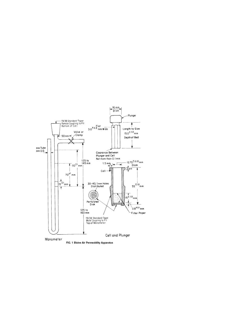
11
the permeability cell shall have a line etched around the tube at 125 to
145 mm below the top side outlet and also others at distances of 15 ± 1
mm, 70 ± 1 mm, and 110 ± 1 mm above that line. A side outlet shall be
provided at 250 to 305 mm above the bottom of the manometer for use in
the evacuation of the manometer arm connected to the permeability cell.
A positive airtight valve shall be provided on the side outlet not more
than 50 mm from the manometer arm.
2.7 Manometer Liquid—The manometer shall be filled to the midpoint
with a nonvolatile, nonhygroscopic liquid of low viscosity and density,
paraffin.
2.8 Timer—The timer shall have a positive starting and stopping
mechanism and shall be capable of being read to the nearest 0.5 s or less.
3. Preparation of Bed of Cement—Seat the perforated disk on the ledge
in the permeability cell, marked face down. Place a filter paper disk on
the metal disk and press the edges down with a rod having a diameter
slightly smaller than that of the cell. Weigh to the nearest 0.001 g the
quantity of cement and place in the cell. Tap the side of the cell lightly in
order to level the bed of cement. Place a filter paper disk on top of the
cement and compress the cement with the plunger until the plunger collar
is in contact with the top of the cell.

11
4.Permeability Test:
4.1 Attach the permeability cell to the manometer tube, making certain
that an airtight connection is obtained and taking care not to disturb the
prepared bed of cement.
4.2 Slowly evacuate the air in the one arm of the manometer U-tube until
the liquid reaches the top mark, and then close the valve tightly. Start the
timer when the bottom of the meniscus of the manometer liquid reaches
the second (next to the top) mark and stop when the bottom of the
meniscus of liquid reaches the third (next to the bottom) mark. Note the
time interval measured and record in seconds. Note the temperature of
test and record in degrees Celsius.
12
Standard Test Method for Density of Hydraulic Cement. C 188
1. Scope
1.1 This test method covers determination of the density of hydraulic
cement.
1.2 The density of hydraulic cement is defined as the mass of a unit
volume of the material.
2. Apparatus
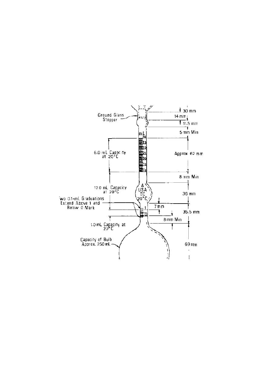
2.1 Le Chatelier flask—The standard flask which is circular in cross
section with shape and dimensions conforming essentially to Fig.1.
Fig. 1 : Le Chatelier Flask for Density Test
The material of construction shall be best quality glass. The glass shall be
chemically resistant.They shall be of sufficient thickness to ensure
reasonable resistance to breakage. The neck shall be graduated from 0 to
1 mL and from 18 to 24 mL in 0.1-mL graduations. The error of any
indicated capacity shall not be greater than 0.05 mL.
2.2 Kerosine, free of water, or naphtha, having a density greater than 0.73
g/ mL at 23 ± 2° C .

13
3. Procedure
3.1 Fill the flask with either of the liquids specified in 2.2 to a point
between the 0 and the 1-mL mark then record the first reading .
3.2 Introduce a quantity of cement, weighed to the nearest 0.05 g, (about
64 g for portland cement).Take care to avoid splashing and see that the
cement does not adhere to the inside of the flask above the liquid .A
vibrating apparatus may be used to accelerate the introduction of the
cement into the flask and to prevent the cement from sticking to the neck.
After all the cement has been introduced, place the stopper in the flask
and roll the flask in an inclined position, so as to free the cement from air
until no further air bubbles rise to the surface of the liquid.
When the
level of the liquid will be in its final position at some point of the upper
series of graduations, take the final reading.
4. Calculation
The difference between the first and the final readings represents the
volume of liquid displaced by the mass of cement used in the test.
Density= weight of sample of cement/ difference between the first and
the final readings

14
Designation: C 109/C 109M – 99
Standard Test Method for Compressive Strength of Hydraulic
Cement Mortars (Using 2-in. or [50-mm] Cube Specimens)1
1. Scope
This test method covers determination of the compressive strength of
hydraulic cement mortars, using 2-in. or [50-mm] cube specimens.
2. Summary of Test Method
The mortar used consists of 1 part cement and 2.75 parts of sand
proportioned by mass. Portland or air-entraining portland cements are
mixed at specified water/cement ratios. Water content for other cements
is that sufficient to obtain a flow of 110 6 5 in 25 drops of the flow table.
Two-inch or [50-mm] test cubes are compacted by tamping in two layers.
The cubes are cured one day in the molds and stripped and immersed in
lime water until tested.
3. Significance and Use
This test method provides a means of determining the compressive
strength of hydraulic cement and other mortars and results may be used to
determine compliance with specifications. Caution must be exercised in
using the results of this test method to predict the strength of concretes.
4. Apparatus
4.1 Weights and Weighing Devices, The weighing device shall be
evaluated for precision and bias at a total load of 2000 g.
4.2 Glass Graduates.
4.3 Specimen Molds, for the 2-in. or [50-mm] cube specimens shall be
tight fitting. The molds shall have not more than three cube compartments
and shall be separable into not more than two parts.
4.4 Mixer.
4.5 Flow Table and Flow Mold.
4.6 Tamper, a nonabsorptive, nonabrasive, nonbrittle material seasoned
oak wood shall have a cross section of about [13 by 25 mm] and a
convenient length of [120 to 150 mm]. The tamping face shall be flat and
at right angles to the length of the tamper.
4.7 Trowel.
4.8 Moist Cabinet or Room.
4.9 Testing Machine.
5. Materials
5.1 Graded Standard Sand:
The sand used for making test specimens shall be natural silica sand
conforming to the requirements for graded standard sand in Specification
C 778.
5.1 Cement.
5.3 Water

15
6. Temperature and Humidity
6.1 Temperature—The temperature of the air in the vicinity of the mixing
slab, the dry materials, molds, base plates, and mixing bowl, shall be
maintained between [20 and 27.5°C].
6.2 Humidity—The relative humidity of the laboratory shall be not less
than 50 %.
7. Test Specimens
Make two or three specimens from a batch of mortar for each period of
test or test age.
8. Preparation of Specimen Molds
8.1Apply a thin coating of release agent to the interior faces of the mold
and non-absorptive base plates. Apply oils and greases using an
impregnated cloth or other suitable means.
8.2 Seal the surfaces where the halves of the mold join by applying a
coating of light cup grease such as petrolatum.
8.3 After placing the mold on its base plate carefully remove with a dry
cloth any excess oil or grease from the surface of the mold and the base
plate .
9. Procedure
9.1 Composition of Mortars:
9.1.1 The proportions of materials for the standard mortar shall be one
part of cement to 2.75 parts of graded standard sand by weight. Use a
water-cement ratio of 0.485 for all portland cements. and 0.460 for all air-
entraining Portland cements. The amount of mixing water for other than
Portland and air-entraining portland cements shall be such as to produce
a flow of 110 ±5.
9.1.2 The quantities of materials to be mixed at one time in the batch of
mortar for making six and nine test specimens shall be as follows:
Number of Specimens
6 9
cement 500 740
sand 1375 2035
Water, mL
Portland (0.485) 242 359
9.2 Molding Test Specimens:
Start molding the specimens within a total elapsed time of not more than
2 min and 30 s after completion of the original mixing of the mortar
batch. Place a layer of mortar about 1 in. or [25 mm] (approximately one
half of the depth of the mold) in all of the cube compartments. Tamp the
mortar in each cube compartment 32 times in about 10 s in 4 rounds, each
round to be at right angles to the other and consisting of eight adjoining
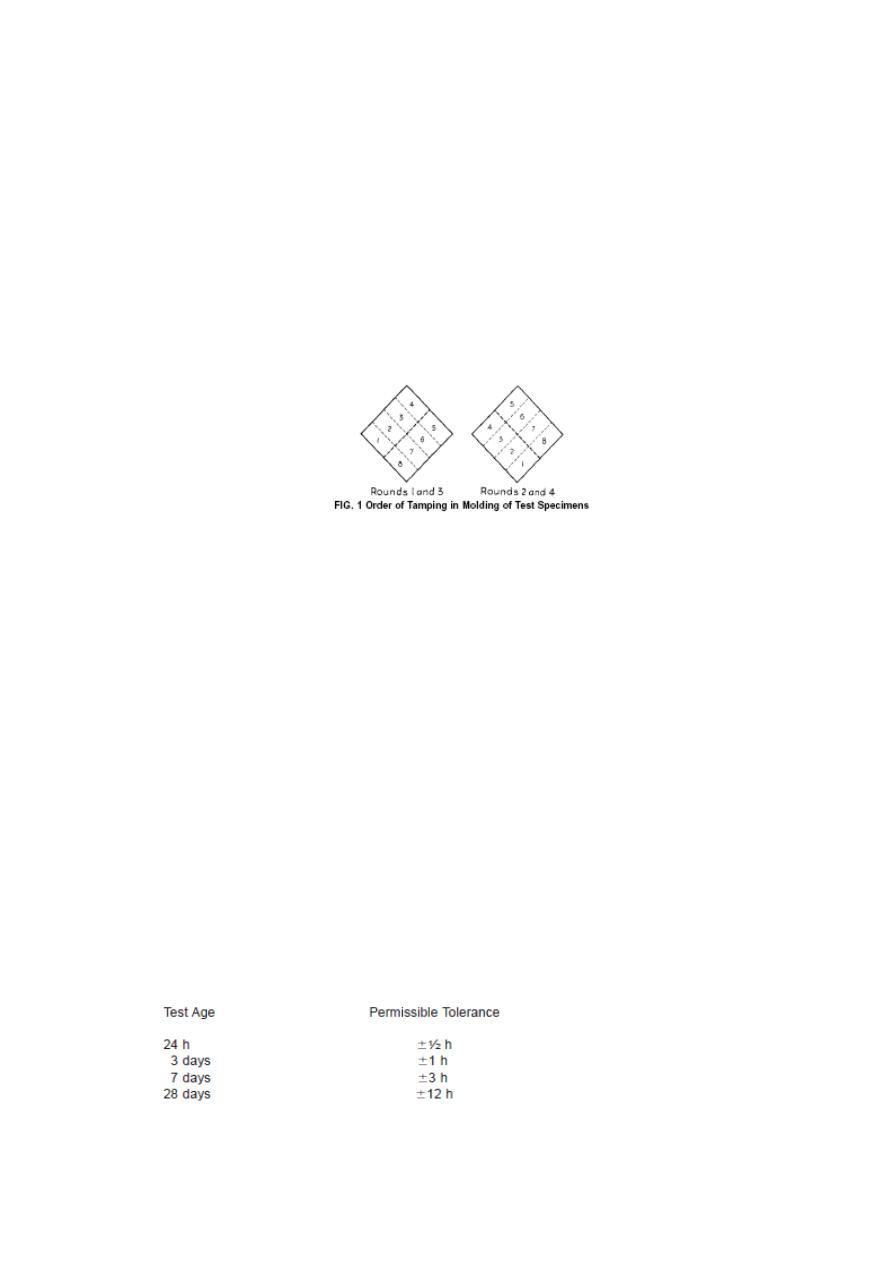
16
strokes over the surface of the specimen, as illustrated in Fig. 1.The 4
rounds of tamping (32 strokes) of the mortar shall be completed in one
cube before going to the next.
When the tamping of the first layer in all
of the cube compartments is completed, fill the compartments with the
remaining mortar and then tamp as specified for the first layer. On
completion of the tamping, the tops of all cubes should extend slightly
above the tops of the molds. Bring in the mortar that has been forced out
onto the tops of the molds with a trowel and smooth off the cubes by
drawing the flat side of the trowel (with the leading edge slightly raised)
once across the top of each cube at right angles to the length of the mold.
9.3 Storage of Test Specimens—Immediately upon completion of
molding, place the test specimens in the moist closet or moist room. Keep
all test specimens, immediately after molding, in the molds on the base
plates in the moist closet or moist room from 20 to 72 h with their upper
surfaces exposed to the moist air but protected from dripping water. If the
specimens are removed from the molds before 24 h, keep them on the
shelves of the moist closet or moist room until they are 24-h old, and then
immerse the specimens, except those for the 24-h test, in saturated lime
water in storage tanks constructed of noncorroding materials. Keep the
storage water clean by changing as required, keep these specimens in
water at a temperature of [23 ± 2°C] and of sufficient depth to completely
immerse each specimen until time of testing.
9.4 Determination of Compressive Strength:
9.4.1 Test the specimens immediately after their removal from the moist
closet in the case of 24-h specimens, and from storage water in the case
of all other specimens ,
All test specimens for a given test age shall be
broken within the permissible tolerance prescribed as follows:

17
9.4.2 Wipe each specimen to a surface-dry condition, and remove any
loose sand grains or incrustations from the faces that will be in contact
with the bearing blocks of the testing machine.
9.4.3 Apply the load to specimen faces that were in contact with the true
plane surfaces of the mold. Apply the load rate with the range of [900 to
1800 N/S].
10. Calculation
Record the total maximum load indicated by the testing machine, and
calculate the compressive strength as follows:
fm = P/A (1)
where:
fm = compressive strength in [MPa],
P = total maximum load in [N], and
A=area of loaded surface [mm
2
].
18
Standard Test Method for Tensile Strength of Hydraulic C260
Cement Mortars
1. Scope
This test method covers the determination of the tensile strength of
hydraulic cement mortar by using the briquet specimen.
2. Significance and Use
Researchers in the field of hydraulic cement have recognized the need for
improved tensile strength. This test method allows for the determination
of tensile strength of a hydraulic cement mortar by casting and testing
briquet specimens.
3. Apparatus
3.1 Weighing Devices
3.2 Sieves:
3.3 Glass Graduates
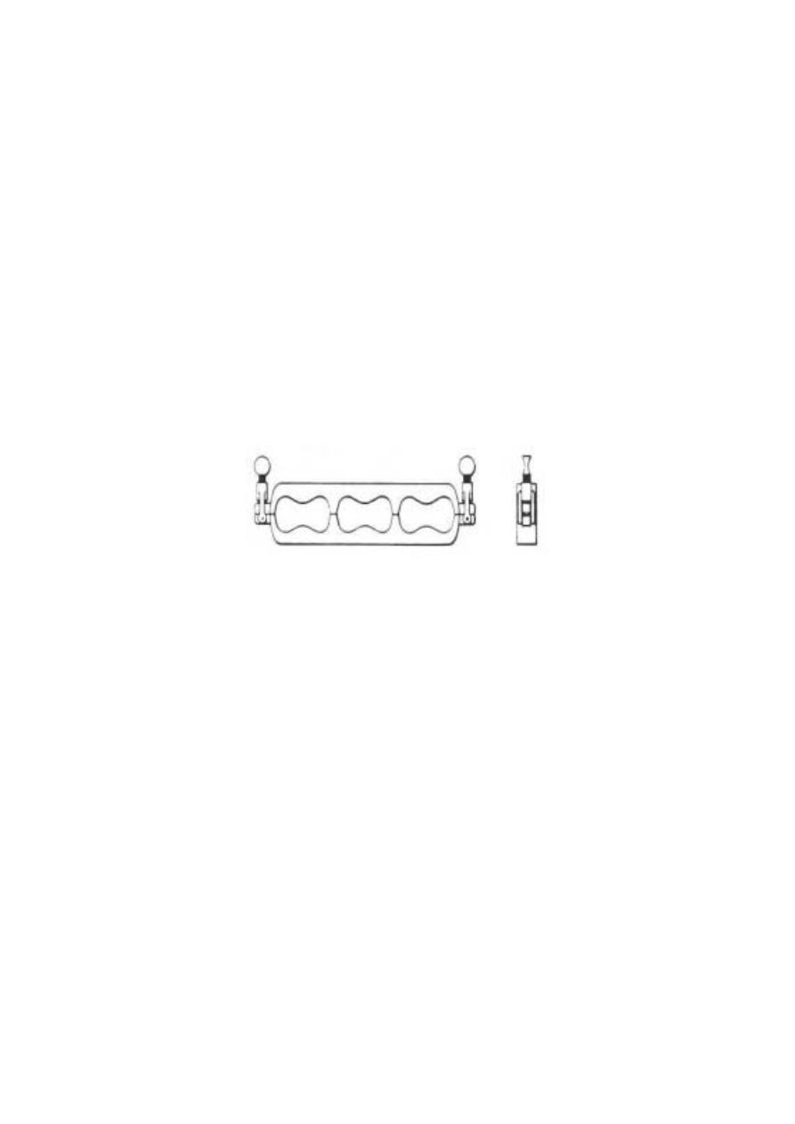
3.4 Briquet Molds
as shown in Fig. 1.
Fig. 1. Briquet Gang Mold
3.5 Trowel
3.6 Testing Machine .
3.7 standard sand.
4. Temperature and Humidity
4.1 Temperature—The temperature of the air in the vicinity of the mixing
slab, the dry materials, molds, base plates, and mixing bowl, shall be
maintained between [20 and 27.5°C].
4.2 Humidity—The relative humidity of the laboratory shall be not less
than 50 %.
5. Number of Briquets
Three or more briquets shall be made for each period of test specified.
6. Procedure
6.1 Proportioning, Consistency, and Mixing of Mortars:
6.1.1 The proportions of the standard mortar shall be 1 part cement to 3
parts standard sand by weight
.
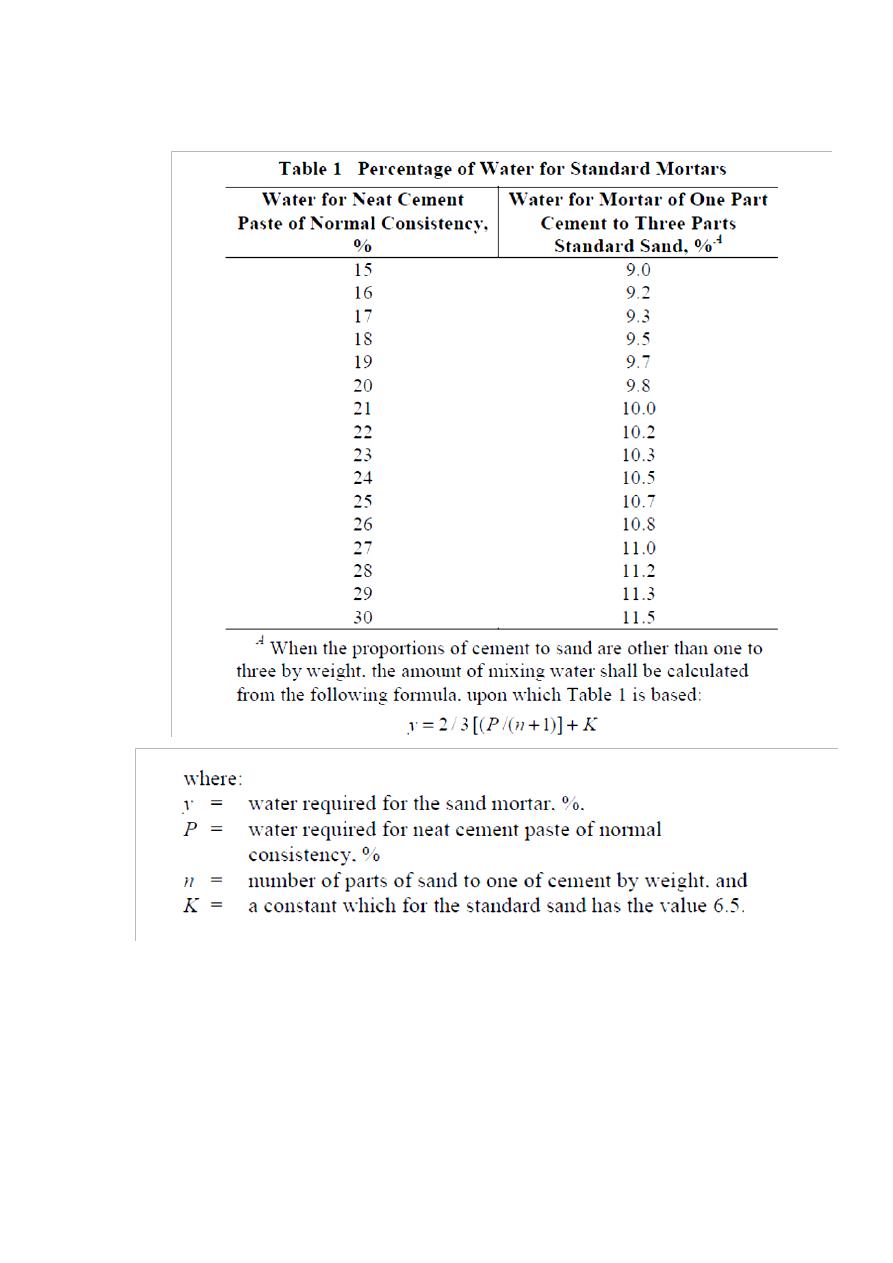
The percentage of water used in the
standard mortar shall depend upon the percentage of water required to
produce a neat cement paste of normal consistency from the same sample
of cement and shall be as indicated in Table 1.
19
6.1.2 Weigh the dry materials, place them upon a smooth nonabsorbent
surface, mix dry, and form a crater in the center. Pour the proper
percentage of clean water into the crater, and turn the material on the
outer edge into the crater within 30 s by the aid of a trowel. After an
additional interval of 30 s for the absorption of the water, during which
21
interval lightly trowel the dry mortar around the outside of the cone over
the remaining mortar to reduce the evaporation losses and to promote
absorption, complete the operation by kneading with the hands for 1-1/2
min. During the operation of mixing, protect the hands with fitting rubber
gloves.
6.2 Molding Test Specimens:
Before being filled, thinly cover the molds with a film of mineral oil, then
fill the molds without compacting. Then press the mortar in with the
thumbs, applying the force 12 times to each briquet. Then bring the
mortar above the mold and smooth it off with a trowel. Cover the mold
with a plane glass or metal plate oiled with oil, and turn over the mold
and plates rotating the mold about its longitudinal axis
.
Remove the top
plate and repeat the operation of heaping, thumbing, and smoothing off.
6.3 Storage of Test Specimens:
Keep all test specimens, immediately after molding, in the molds on the
base plates in the moist closet or moist room for from 20 to 24 h then
immerse the specimens in saturated lime water in storage tanks
constructed of noncorroding materials.
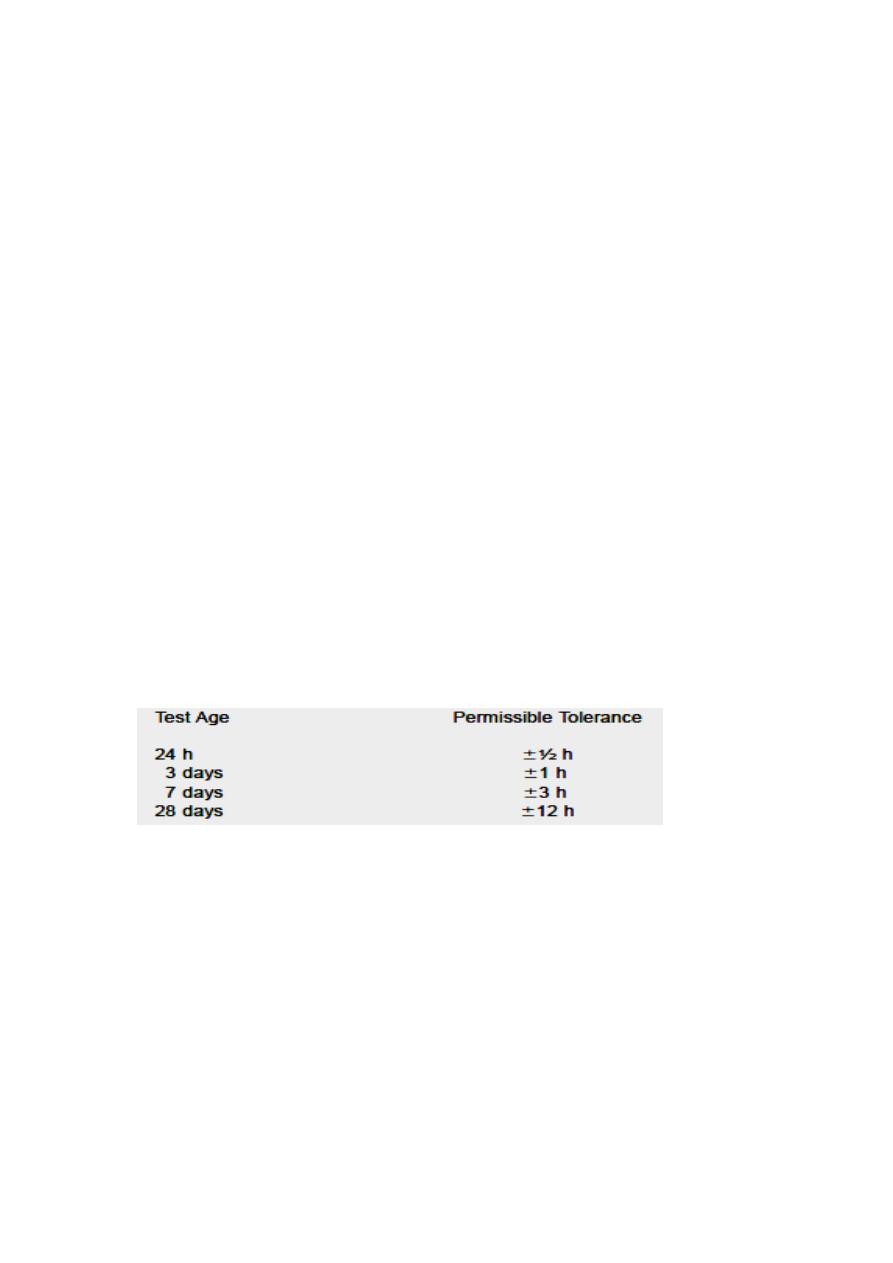
6.4 Determination of Tensile Strength:
6.4.1 Test the briquet specimens immediately after their removal from the
moist closet for 24-h specimens, and from storage water for all other
specimens. Break all test specimens for a given test age within the
permissible tolerance pre. scribed in the following table:
6.4.2 Wipe each briquet to a surface-dry condition, and remove any loose
sand grains or incrustations from the surfaces that will be in contact with
the clips of the testing machine.
7. Calculation
Record the total maximum load indicated by the testing machine, and
calculate the compressive strength as follows:
fm = P/A
where:
fm = compressive strength in [MPa],
P = total maximum load in [N], and
A=area of failure surface [mm
2
].

21
Designation: C 151
Standard Test Method for Autoclave Expansion of Portland
Cement1
1. Scope
This test method covers determination of the autoclave expansion of
portland cement by means of a test on a neat cement specimen.
3. Apparatus
3.1 Weighing Devices and Weights, for determining the mass of materials
conforming to the requirements of Specification C 1005.
3.2 Glass Graduates, 200 or 250-mL capacity, and conforming to the
requirements of Practice C 490.
3.3 Molds, 1 by 1-in. (25.4 by 25.4-mm) cross section.
3.4 Flat Trowel, having a straight-edged steel blade.(100 to 150 mm) in
length.
3.5 Autoclave, consisting of a high-pressure steam vessel provided with a
thermometer well. The autoclave shall be equipped with an automatic
pressure control and a rupture disk with a bursting pressure of (2.4 MPa)
±5 %. In locations where the use of a rupture disk is not permitted, the
autoclave shall be equipped with a safety valve. In addition, the autoclave
shall be equipped with a vent valve to allow the escape of air during the
early part of the heating period and to release any steam pressure
remaining at the end of the cooling period. The pressure gage shall have a
nominal capacity of (4.1 MPa), a dial with a nominal diameter of (114
mm) and shall be graduated from (0 to 4.1 MPa) with scale divisions not
exceeding (0.03 MPa). The error in the gage shall not exceed (±0.02
MPa) at the operating pressure of (2 MPa). The capacity of the heating
unit shall be such that with maximum load (water plus specimens) the
pressure of the saturated steam in the autoclave may be raised to a gage
pressure of 2.0Mpa in 45 to 75 min from the time the heat is turned on.
The automatic pressure control shall be capable of maintaining the gage
pressure at (2 ± 0.07 MPa) for at least 3 h. A gage pressure of
2.0±0.07Mpa corresponds to a temperature of (216±2°C). The autoclave
shall be designed to permit the gage pressure to drop from 2.0Mpa to less
than 0.07 in 1 1⁄2h after the heat supply has been shut off.
3.5.1 Rupture Disk—The rupture disk shall be made of a material having
a tensile strength that is relatively insensitive to temperature in the range
68 to 420°F (20 to 216°C) .
3.6 Length Comparator—The comparator used for measuring length
change of specimens shall conform to the requirements of Practice C 490.

22
4. Temperature and Humidity
4.1 Molding Room—Maintain the temperature of the molding room, dry
materials and mixing water, and the relative humidity of the molding
room within the limits of Practice C 490.
4.2 Moist Storage Facilities—Maintain the temperature and humidity of
the moist storage facilities to the requirements of Specification C 511.
5. Preparation of Test Specimens
5.1 Mixing Cement Paste—Prepare the standard batch consisting of 650 g
of cement and sufficient water to give a paste of normal consistency.
5.2 Molding Specimens—Immediately following preparation of the time
of setting specimen or completion of mixing, mold the test specimen in
two approximately equal layers, each layer being compacted with the
thumbs or forefingers by pressing the paste into the corners, around the
gage studs, and
along the surface of the mold until a homogeneous specimen is obtained.
Compact the top layer, cut off the paste flush with the top of the mold
with a thin-edged trowel, and smooth the surface with a few strokes of the
flat trowel. During the operations of mixing and molding, protect the
hands with
rubber gloves.
5.3 Storage of Test Specimens—After filling the mold, place it in the
moist closet or moist room for at least 20 h.
6. Procedure
6.1 after molding, remove the specimens from the moist atmosphere,
immediately obtain a length comparator reading for each specimen, and
place in the autoclave at room temperature in a rack so that all sides of
the
specimen will be exposed to saturated steam. The autoclave shall contain
enough water, at an initial temperature of (20 to 28°C), to maintain an
atmosphere of saturated steam vapor during the entire test. Ordinarily 7 to
10 % of the volume of the autoclave should be occupied by the water.
6.2 To permit air to escape from the autoclave during the early portion of
the heating period, leave the vent valve open until steam begins to escape.
Close the valve and raise the temperature of the autoclave at a rate that
will bring the gage pressure of the steam to (2 MPa) in 45 to 75 min from
the time the heat is turned on. Maintain the (2 ± 0.07 MPa) pressure for 3
h. At the end of the 3-h period, shut off the heat supply and cool the
autoclave at such a rate that the pressure will be less than 0.07Mpa at the
end of 1 1/2 h. At the end of the 1 1/2h period, slowly release any
remaining pressure by partially opening the vent valve until atmospheric
pressure is attained. Then open the autoclave and place the test specimen
in water at a temperature above (90°C). Cool the water surrounding the
bars at a uniform rate by adding cold water so that the temperature of the

23
water will be lowered to \ (23°C) in 15 min. Maintain the water
surrounding the specimens at 23°C for an additional 15 min; then,
surface-dry the specimens and obtain a length comparator reading for
each specimen.
7. Calculation
Calculate the change in length of the test specimen by subtracting the
length comparator reading before autoclaving from that after autoclaving,
and report as percent of effective gage length to the nearest 0.01 %.
Report the percentage of increase in length as the autoclave expansion.
Indicate a decrease in length by a minus sign prefixed to the percent
value.

24
Designation: C 702
American Association State Highway and Transportation Officials
Standard: T 248
Standard Practice for Reducing Samples of Aggregate to Testing
Size1
1. Significance and Use
This practice provides procedures for reducing the large sample obtained
in the field or produced in the laboratory to a convenient size for
conducting a number of tests to describe the material and measure its
quality in a manner that the smaller test sample portion is most likely to
be a representation of the larger sample, and thus of the total supply.
2. Selection of Method
2.1 Fine Aggregate—Reduce the size of samples of fine aggregate that
are drier than the saturated-surface-dry condition using a mechanical
splitter according to Method A. Reduce the size of samples having free
moisture on the particle surfaces by quartering according to Method B, or
by treating as a miniature stockpile as described in Method C.
2.1.1 If the use of Method B or Method C is desired, and the sample does
not have free moisture on the particle surfaces, moisten the sample to
obtain free moisture on the particle surfaces, mix thoroughly, and then
reduce the sample size.
2.1.2 If use of Method A is desired and the sample has free moisture on
the particle surfaces, dry the sample to at least the saturated-surface-dry
condition, and then reduce the sample size.
2.2 Coarse Aggregates and Mixtures of Coarse and Fine Aggregates—
Reduce the sample using a mechanical splitter in accordance with
Method A (preferred method) or by quartering in accordance with
Method B. The miniature stockpile Method C is not permitted for coarse
aggregates or mixtures of coarse and fine aggregates.
Weight of sampling
Size of particles(mm) Size of particles (in)
Minimum weight of
sample
≥ 25
≥ 1.0
50
5< max. agg<25
3/16<Max.agg<1.0
25
<5
<3/16
13
25
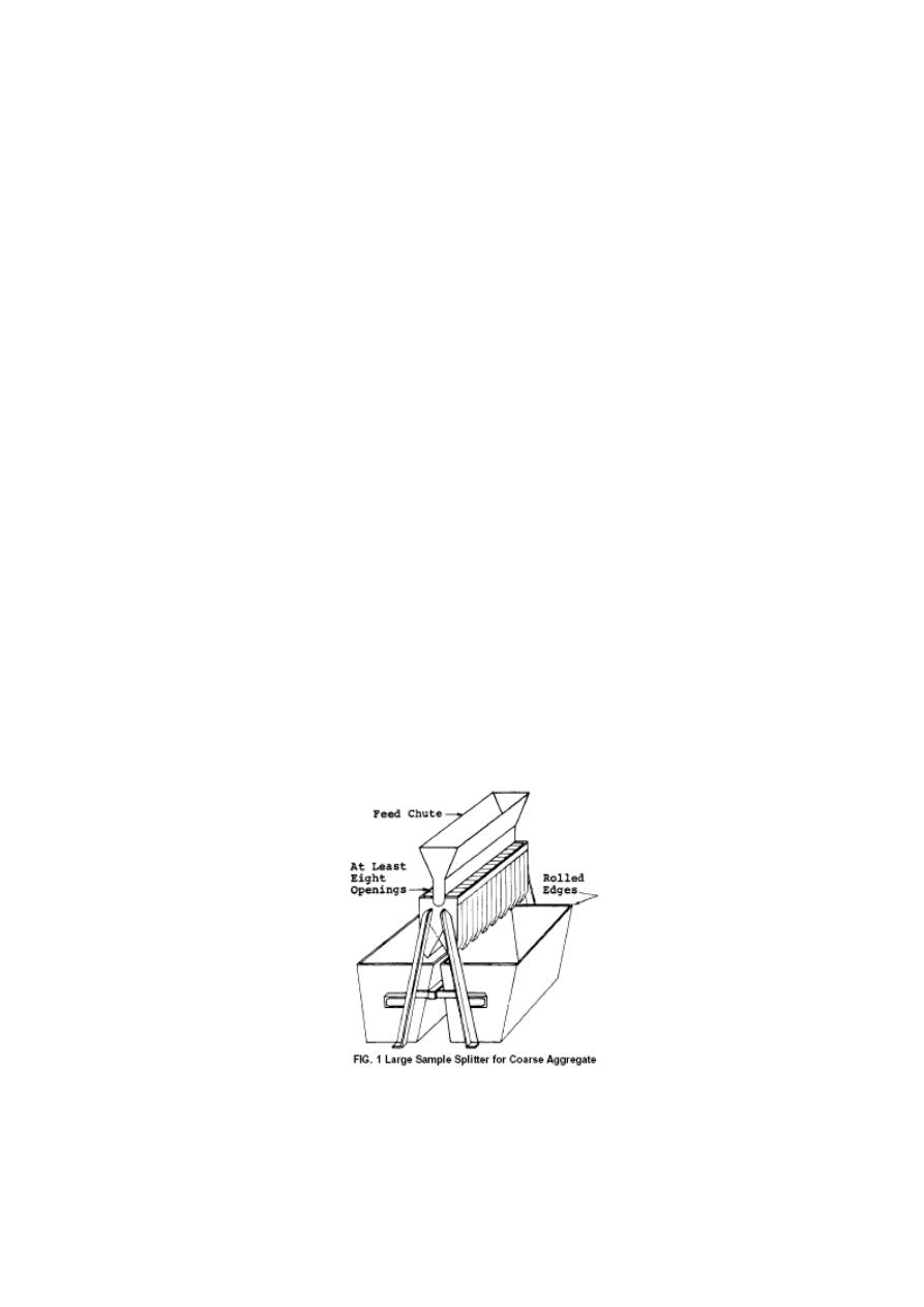
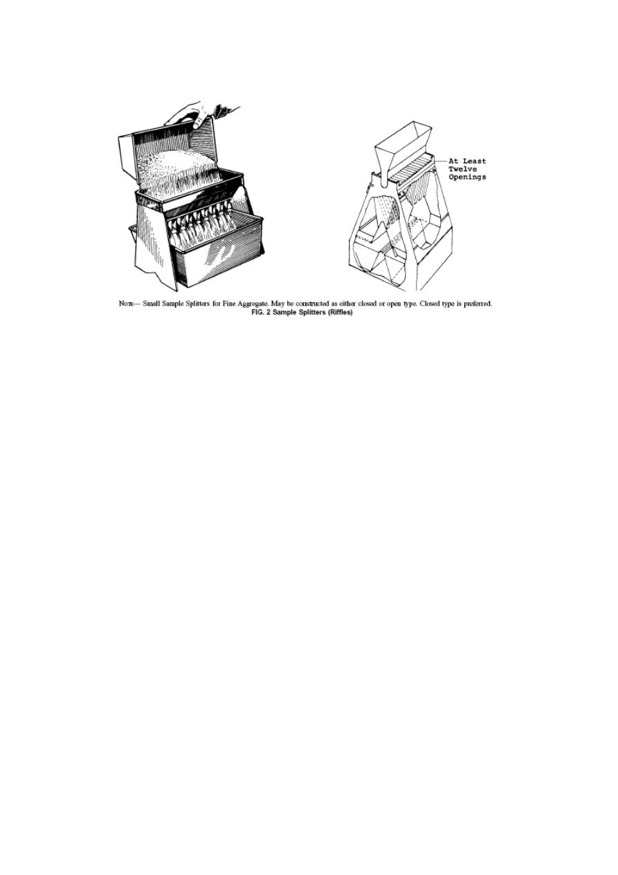
METHOD A—MECHANICAL SPLITTER
3. Apparatus
3.1 Sample Splitter—Sample splitters shall have an even number of equal
width chutes, but not less than a total of eight for coarse aggregate, or
twelve for fine aggregate, which discharge alternately to each side of the
splitter. For coarse aggregate and mixed aggregate, the minimum width of
the individual chutes shall be approximately 50 % larger than the largest
particles in the sample to be split. For dry fine aggregate in which the
sample will pass the 9.5-mm (3⁄8-in.) sieve , a splitter having chutes 12.5
to 20 mm wide shall be used. The splitter shall be equipped with two
receptacles to hold the two halves of the sample following splitting. It
shall also be equipped with a straight edged pan. The splitter and
accessory equipment shall be so designed that the sample will flow
smoothly without restriction or loss of material (see Fig. 1 and Fig. 2).
4. Procedure
4.1 Place the original sample in the pan and uniformly distribute it from
edge to edge, so that when it is introduced into the chutes, approximately
equal amounts will flow through each chute. Reintroduce the portion of
the sample in one of the receptacles into the splitter as many times as
necessary to reduce the sample to the size specified for the intended test.
Reserve the portion of material collected in the other receptacle for
reduction in size for other tests, when required.
26
METHOD B—QUARTERING
5. Apparatus
5.1 Apparatus shall consist of a shovel, or trowel; a broom or brush; and a
canvas blanket approximately 2 by 2.5 m.
6. Procedure
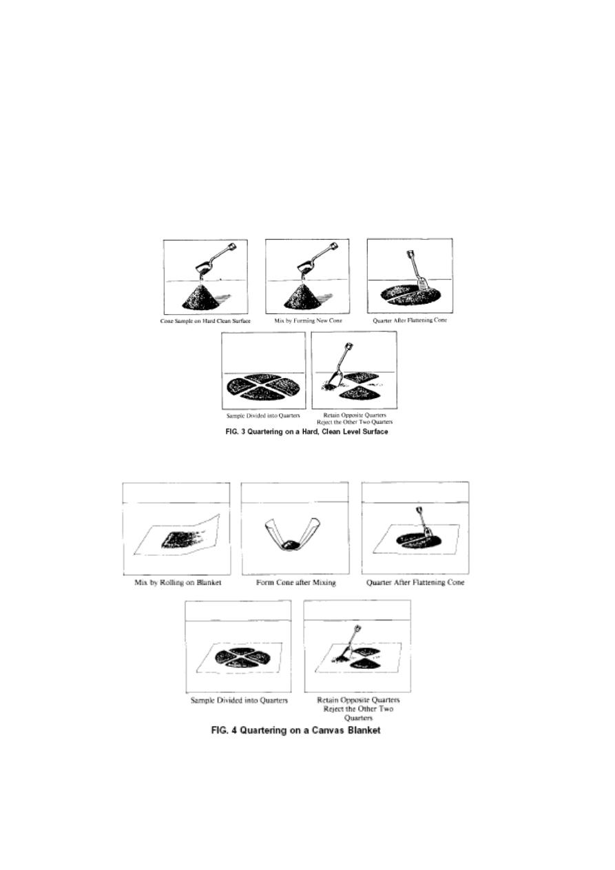
6.1.1 Place the original sample on a hard, clean, level surface where there
will be neither loss of material nor the accidental addition of foreign
material. Mix the material by turning the entire sample over three times.
With the last turning, shovel the entire sample into a conical pile.
Carefully flatten the conical pile to a uniform thickness and diameter by
pressing down the apex with a shovel. The diameter should be
approximately four to eight times the thickness. Divide the flattened mass
into four equal quarters with a shovel or trowel and remove two
diagonally opposite quarters, including all fine material, and brush the
cleared spaces clean. Successively mix and quarter the remaining material
until the sample is reduced to the desired size (Fig. 3).
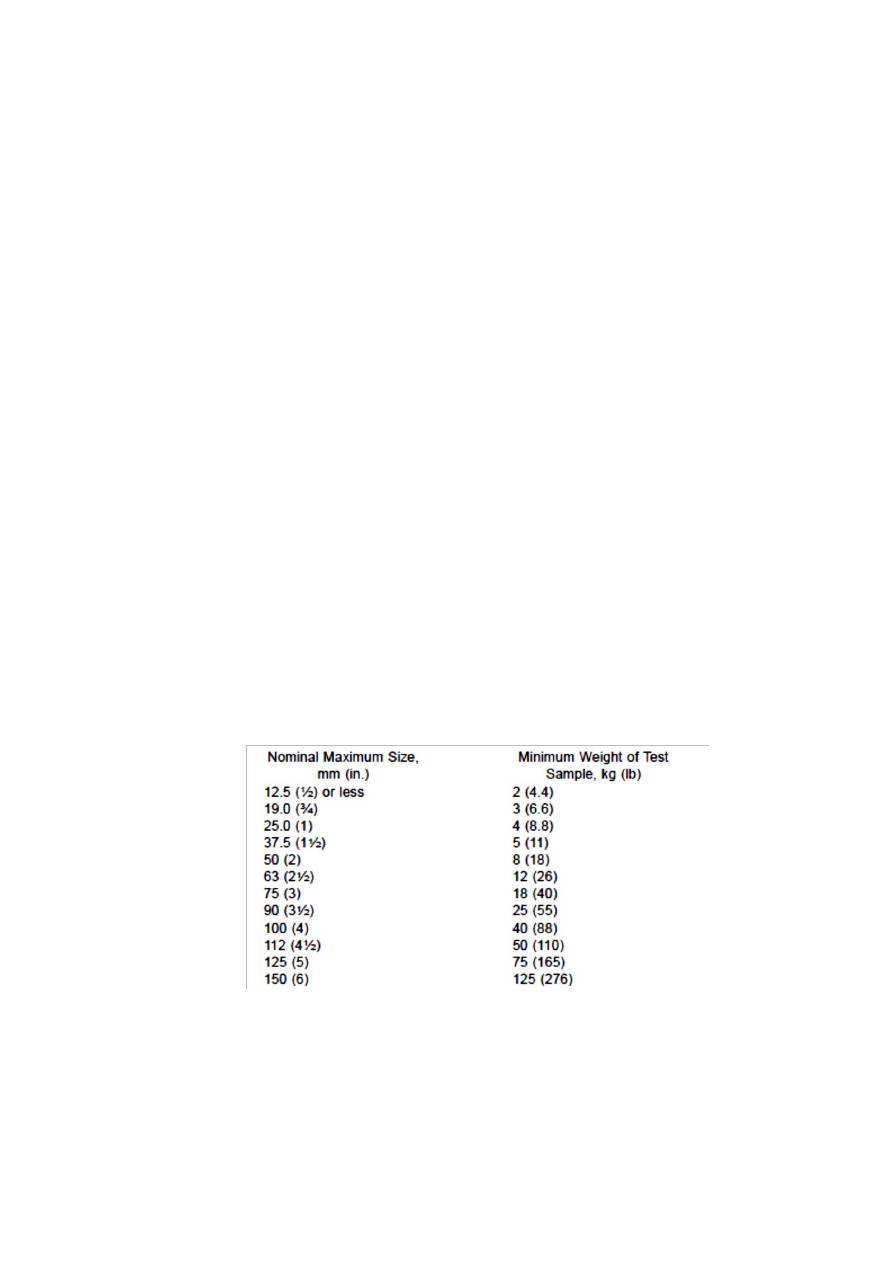
6.1.2 As an alternative to the procedure described in 6.1.1, when the floor
surface is uneven, place the field sample on a canvas blanket and mix
with a shovel as described in 6.1.1, or by alternately lifting each corner of
the canvas and pulling it over the sample toward the diagonally opposite
corner causing the material to be rolled. Flatten the pile as described in
6.1.1. Divide the sample as described in 6.1.1, or if the surface beneath
the blanket is uneven, insert a stick or pipe beneath the blanket and under
27
the center of the pile, then lift both ends of the stick, dividing the sample
into two equal parts. Remove the stick leaving a fold of the blanket
between the divided portions. Insert the stick under the center of the pile
at right angles to the first division and again lift both ends of the stick,
dividing the sample into four equal parts. Remove two diagonally
opposite quarters, being careful to clean the fines from the blanket.
Successively mix and quarter the remaining material until the sample is
reduced to the desired size (Fig. 4).
METHOD C—MINIATURE STOCKPILE SAMPLING
(DAMP FINE AGGREGATE ONLY)

28
7. Apparatus
7.1 Apparatus shall consist of a straight-edged scoop, shovel, or trowel
for mixing the aggregate, and either a small sampling, small scoop, or
spoon for sampling.
8. Procedure
8.1 Place the original sample of damp fine aggregate on a hard clean,
level surface where there will be neither loss of material nor the
accidental addition of foreign material. Mix the material thoroughly by
turning the entire sample over three times. With the last turning, shovel
the entire sample into a conical pile. If desired, flatten the conical pile to a
uniform thickness and diameter by pressing down the apex with a shovel
so that each quarter sector of the resulting pile will contain the material
originally in it. Obtain a sample for each test by selecting at least five
increments of material at random locations from the miniature stockpile,
using any of the sampling devices described in 7.1.

29
Standard Test Method for
Materials Finer than 75-μm (No. 200) Sieve in Mineral Aggregates by
Washing1
1. Scope
1.1 This test method covers determination of the amount of material finer
than a 75-μm (No. 200) sieve in aggregate by washing. Clay particles and
other aggregate particles that are dispersed by the wash water, as well as
water-soluble materials, will be removed from the aggregate during the
test.
1.2 Two procedures are included, one using only water for the washing
operation, and the other including a wetting agent to assist the loosening
of the material finer than the 75-μm (No. 200) sieve from the coarser
material.
2. Significance and Use
Plain water is adequate to separate the material finer than 75 μm from the
most aggregates.
3. Apparatus and Materials
3.1 Balance—A balance or scale readable and accurate to 0.1 g.
3.2 Sieves—A nest of two sieves, the lower being a 75-μm (No. 200)
sieve and the upper a 1.18-mm (No. 16) sieve.
3.3 Container—A pan sufficient to contain the sample covered with
water and to permit vigorous agitation without loss of any part of the
sample or water.
3.4 Oven—An oven of sufficient size, capable of maintaining a uniform
temperature of 110 ±5°C.
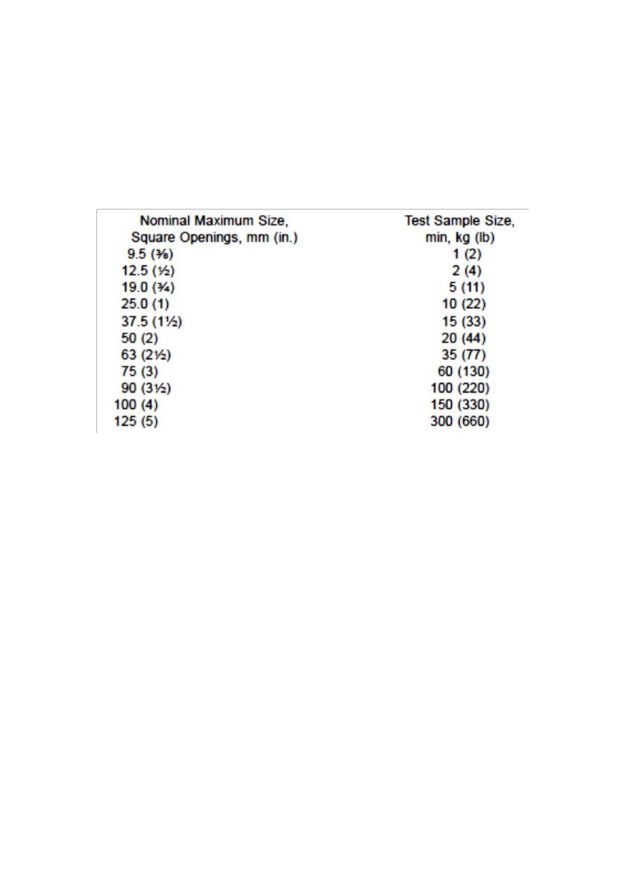
4. Sampling
Thoroughly mix the sample of aggregate to be tested and reduce the
quantity to an amount suitable for testing using the applicable methods
described in Practice C 702. The mass of the test sample, after drying,
shall conform with the following:
5. Procedure A—Washing with Plain Water
5.1 Dry the test sample to constant mass at a temperature of 110 ± 5°C.
Determine the mass test sample.

31
5.2 After drying and determining the mass, place the test sample in the
container and add sufficient water to cover it. No detergent, dispersing
agent shall be added to the water. Agitate the sample with sufficient vigor
to result in complete separation of all particles finer than the 75-μm (No.
200) sieve from the coarser particles, and to bring the fine material into
suspension. Immediately pour the wash water containing the suspended
and dissolved solids over the nested sieves, arranged with the coarser
sieve on top. Take care to avoid the exiting coarser particles from the
sample.
5.3 Add a second charge of water to the sample in the container, agitate,
and decant as before. Repeat this operation until the wash water is clear.
5.4 Return all material retained on the nested sieves by flushing to the
washed sample. Dry the washed aggregate to constant mass at a
temperature of 110 ± 5°C and determine the mass of the sample.
6. Calculation
6.1 Calculate the amount of material passing a 75-μm (No. 200) sieve by
washing as follows:
where:
A = Percentage of material finer than a 75-μm (No. 200) sieve by
washing.
B = Original dry mass of sample, g.
C = Dry mass of sample after washing, g.

31
Designation: C 127
Standard Test Method for
Specific Gravity and Absorption of Coarse Aggregate1
1. Scope
1.1 This test method covers the determination of specific gravity and
absorption of coarse aggregate. The specific gravity may be expressed as
bulk specific gravity, bulk specific gravity (SSD) (saturated-surface-dry),
or apparent specific gravity.
2. Definitions:
2.1 Absorption—the increase in the weight of aggregate due to water in
the pores of the material, but not including water adhering to the outside
surface of the particles, expressed as a percentage of the dry weight. The
aggregate is considered “dry” when it has been maintained at a
temperature of 110 ± 5°C for sufficient time to remove all water.
2.2 Specific gravity—the ratio of the mass (or weight in air) of a unit
volume of a material to the mass of the same volume of water. Values are
dimensionless.
2.3 Apparent specific gravity—the ratio of the weight in air of a unit
volume of the impermeable portion of aggregate at to the weight in air of
an equal volume of distilled water.
2.4 Bulk specific gravity—the ratio of the weight in air of a unit volume
of aggregate (including the permeable and impermeable voids in the
particles, but not including the voids between particles) to the weight in
air of an equal volume distilled water.
2.5 Bulk specific gravity (SSD)—the ratio of the weight in air of a unit
volume of aggregate, including the weight of water within the voids filled
to the extent achieved by submerging in water for approximately 24 h
(but not including the voids between particles), compared to the weight in
air of an equal volume of distilled.
3. Summary of Test Method
A sample of aggregate is immersed in water for approximately 24 h to
essentially fill the pores. It is then removed from the water, the water
dried from the surface of the particles, and weighed. Subsequently the
sample is weighed while submerged
in water. Finally the sample is oven-dried and weighed it. Using the
weights thus obtained and formulas in this test method, it is possible to
calculate three types of specific gravity and absorption.
4. Significance and Use
4.1 Bulk specific gravity is the characteristic generally used for
calculation of the volume occupied by the aggregate in various mixtures
containing aggregate, Bulk specific gravity is also used in the
computation of voids in aggregate in Test Method C 29. Bulk specific
32
gravity (SSD) is used if the aggregate is wet, that is, if its absorption has
been satisfied. Conversely, the bulk specific gravity (oven-dry) is used for
computations when the aggregate is dry or assumed to be dry.
4.2 Apparent specific gravity is the relative density of the solid material
making up the particles not including the pore space within the particles
which is accessible to water.
4.3 Absorption values are used to calculate the change in the weight of an
aggregate due to water absorbed in the pore spaces.
5. Apparatus
5.1 Balance—A weighing device that is sensitive, readable, and accurate
to 0.5 g. The balance shall be equipped with suitable apparatus for
suspending the sample container in water.
5.2 Sample Container—A wire basket of 3.35 mm (No. 6) or finer mesh.
5.3 Water Tank—A watertight tank into which the sample container may
be placed while suspended below the balance.
5.4 Sieves—A 4.75-mm (No. 4) sieve
6. Sampling
6.1 Mix the sample of aggregate and reduce it to the approximate quantity
needed using the procedures in Methods C 702. Reject all material
passing a 4.75-mm
(No. 4) sieve by dry sieving and washing to remove other coatings from
the surface.
6.2 The minimum weight of test sample to be used is given below.
8. Procedure
7. Procedure
7.1 Immerse the aggregate in water at room temperature for a period of
24 ± 4 h.
7.2 Remove the test sample from the water and roll it in a large absorbent
cloth until all visible of water are removed. Wipe the larger particles
individually. Take care to avoid evaporation of water from aggregate
33
pores during the surface-drying operation. Weigh and record the test
sample in the saturated surface-dry condition.
7.3 After weighing, immediately place the saturated surface- dry test
sample in the sample container and determine its weight in water at 23±
1.7°C , having a density
of 997 ± 2 kg/m
3
. Take care to remove all entrapped air before weighing
by shaking the container while immersed.
7.4 Dry the test sample to constant weight at a temperature of 110 ± 5°C,
cool in air at room temperature 1 to 3 h, or until the aggregate has cooled
to a temperature that is comfortable to handle (approximately 50°C),
weigh and record the dry sample.
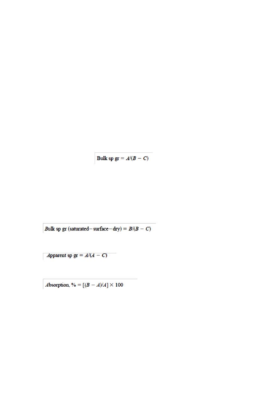
8. Calculations
8.1 Specific Gravity:
8.1.1 Bulk Specific Gravity—Calculate the bulk specific gravity as
follows:
A = weight of oven-dry test sample in air, g,
B = weight of saturated-surface-dry test sample in air, g,
C = weight of saturated test sample in water, g.
8.1.2 Bulk Specific Gravity (Saturated-Surface-Dry)
8.1.3 Apparent Specific Gravity
8.2 Absorption

34
Standard Test Method for
Bulk Density (“Unit Weight”) and Voids in Aggregate1
1. Scope
1.1 This test method covers the determination of bulk density (“unit
weight”) of aggregate in a compacted or loose condition, and calculated
voids between particles in fine, coarse, or mixed aggregates based on the
same determination.
This test method is applicable to aggregates not
exceeding 5 in.
[125 mm] in nominal maximum size.
3. Terminology
3.1 bulk density of aggregate, the mass of a unit volume of bulk
aggregate material, in which the volume includes the volume of the
individual particles and the volume of the voids between the particles.
Expressed in lb/ft3 [kg/m3].
3.2 unit weight, weight (mass) per unit volume.
3.3 voids in unit volume of aggregate, the space between particles in an
aggregate mass not occupied by solid mineral matter. Voids within
particles, either permeable or impermeable, are not included in voids as
determined by this test method.
4. Significance and Use
4.1 This test method is often used to determine bulk density values that
are necessary for use for many methods of selecting proportions for
concrete mixtures.
4.2 The bulk density also may be used for determining mass/volume
relationships for conversions in purchase agreements.
4.3 A procedure is included for computing the percentage of voids
between the aggregate particles based on the bulk density determined by
this test method.
5. Apparatus
5.1 Balance
5.2 Tamping Rod—A round, straight steel rod, 5⁄8 in. [16 mm] in
diameter and approximately 24 in. [600 mm] in length.
5.3 Measure—A cylindrical metal measure, preferably provided with
handles.
It shall be watertight, with the top and bottom true and even, and
sufficiently rigid to retain its form under rough usage. The measure shall
have a height approximately equal to the diameter, but in no case shall the
height be less than 80 % nor more than 150 % of the diameter The top
rim shall be smooth and plane within 0.01 in. [0.25 mm] and shall be

35
parallel to the bottom within 0.5. The interior wall of the measure shall be
a smooth and continuous surface.
5.4 Shovel or Scoop—A shovel or scoop of convenient size for filling the
measure with aggregate.
5.5 Calibration Equipment—A piece of plate glass, at least 1⁄4 in. [6 mm]
thick and at least 1 in. [25 mm] larger than the diameter of the measure to
be calibrated.
6. Sampling
6.1 Obtain the sample in accordance with Practice D 75, and reduce to
test sample size in accordance with Practice C 702.
7. Test Sample
7.1 The size of the sample shall be approximately 125 to 200 % of the
quantity required to fill the measure, and shall be handled in a manner to
avoid segregation. Dry the aggregate sample to essentially constant mass,
preferably in an oven at
230 ± 9°F [110 ±
6 °C].
8. Calibration of Measure
8.1 Fill the measure with water at room temperature and cover with a
piece of plate glass in such a way as to eliminate bubbles and excess
water.
8.2 Determine the mass of the water in the measure using the balance .
8.3 Calculate the volume, V, of the measure by dividing the mass of the
water required to fill the measure by its density.
9. Selection of Procedure
9.1The shoveling procedure for loose bulk density shall be used.
Otherwise, the compact bulk density shall be determined by the rodding
procedure for aggregates having a nominal maximum size of 1.5 in. [37.5
mm] or less, or by the jigging procedure for aggregates having a nominal
maximum size greater than 1.5 in. [37.5 mm] and not exceeding 5 in.
[125 mm].
10. Rodding Procedure
10.1 Fill the measure one-third full and level the surface with the fingers.
Rod the layer of aggregate with 25 strokes.
Fill the measure two-thirds
full and again level and rod as above. Finally, fill the measure to
overflowing and rod again in the
manner previously mentioned. Level the surface of the aggregate with the
fingers or a straightedge.

36
10.2 In rodding the first layer, do not allow the rod to strike the bottom of
the measure. In rodding the second and third layers, use vigorous effort,
but not more force than to cause the tamping rod to penetrate to the
previous layer of aggregate.
10.3 Determine the mass of the measure plus its contents, and the mass of
the measure alone, and record the values to the nearest 0.1 lb [0.05 kg].
11. Shoveling Procedure
11.1 Fill the measure to overflowing by means of a shovel or scoop,
discharging the aggregate from a height not to exceed 2 in. [50 mm]
above the top of the measure. Exercise care to prevent, so far as possible,
segregation of the particle sizes of which the sample is composed. Level
the surface of the aggregate with the fingers or a straightedge .
11.2 Determine the mass of the measure plus its contents, and the mass of
the measure alone, and record the values to the nearest 0.1 lb [0.05 kg].
12. Calculation
12.1 Bulk Density—Calculate the bulk density for the rodding, jigging, or
shoveling procedure as follows:
M =(G – T)/V (1)
where:
M = bulk density of the aggregate, lb/ft
3
[kg/m
3
],
G =mass of the aggregate plus the measure, lb [kg],
T = mass of the measure, lb [kg],
V = volume of the measure, ft
3
[m
3
], and
12.1.1 The bulk density determined by this test method is for aggregate in
an oven-dry condition. If the bulk density in terms of saturated-surface-
dry (SSD) condition is desired, use the exact procedure in this test
method, and then calculate the
SSD bulk density using the following formula:
Mssd=M[1 +A/100] (2)
where:
MSSD = bulk density in SSD condition, lb/ft
3
[kg/m
3
], and A = %
absorption, determined in accordance with Test Method C 127 or Test
Method C 128.
12.2 Void Content—Calculate the void content in the aggregate using the
bulk density determined by either the rodding, jigging, or shoveling
procedure, as follows:
% Voids = 100[(S * W)- M]/(S * W) (3)
where:
M = bulk density of the aggregate, lb/ft
3
[ kg/m
3
],

37
S = bulk specific gravity (dry basis) as determined in accordance with
Test Method C 127 or Test Method C 128,
W= density of water =1000 kg/m
3

38
Standard Test Method for Sieve Analysis of Fine and Coarse
Aggregates C 136
1. Scope
1.1 This test method covers the determination of the particle size
distribution of fine and coarse aggregates by sieving.
2. Summary of Test Method
2.1 A sample of dry aggregate of known mass is separated through a
series of sieves of progressively smaller openings for determination of
particle size distribution.
3. Significance and Use
3.1 This test method is used primarily to determine the grading of
materials proposed for use as aggregates. The results are used to
determine commitment of the particle size distribution with applicable
specification requirements and to provide necessary data for developing
relationships concerning porosity and packing.
3.2 Accurate determination of material finer than the 75-μm (No. 200)
sieve cannot be achieved by use of this method alone. Test Method C 117
for material finer than 75-μm sieve by washing should be taken in
account.
4. Apparatus
4.1 Balances—Balances or scales used in testing fine and coarse
aggregate shall have readability and accuracy as follows:
4.1.1 For fine aggregate, readable to 0.1 g and accurate to 0.1 g.
4.1.2 For coarse aggregate, or mixtures of fine and coarse aggregate,
readable and accurate to 0.5 g .
4.2 Sieves—The sieve cloth shall be mounted on frames constructed in a
manner that will prevent loss of material during sieving.
4.3 Mechanical Sieve Shaker—A mechanical sieving device, if used,
shall create motion of the sieves to cause the particles to bounce, tumble,
or otherwise turn so as to present different orientations to the sieving
surface.
4.4 Oven—An oven of appropriate size capable of maintaining a uniform
temperature of 110 ± 5°C (230± 9°F).
39
5. Sampling
5.1 Sample the aggregate in accordance with Practice C 702.
5.2 Fine Aggregate—The size of the test sample, after drying, shall be
300 g minimum.
5.3 Coarse Aggregate—The size of the test sample of coarse aggregate
shall conform with the following:
5.4 Coarse and Fine Aggregate Mixtures—The size of the test sample of
coarse and fine aggregate mixtures shall be the same as for coarse
aggregate in 5.3.
6. Procedure
6.1 Dry the sample to constant mass at a temperature of 110 ± 5°C (230 ±
9°F).
6.2 Select sieves with suitable openings present the information required
by the specifications covering the material to be tested. Use additional
sieves as desired or necessary to provide other information, such as
fineness modulus, or to regulate the amount of material on a sieve. Nest
the sieves in order of decreasing size of opening from top to bottom and
place the sample on the top sieve. Agitate the sieves by hand or by
mechanical sieve shaker for a sufficient period, established by trial or
checked by measurement on the actual test sample.
6.3 Determine the mass of each size increment on a scale by using
balance. The total mass of the material after sieving should check closely
with original mass of sample placed on the sieves. If the amounts differ
by more than 0.3 %, based on the original dry sample mass, the results
should not be used for acceptance purposes.

41
7. Calculation
7.1 Calculate percentages passing, total percentages retained. If the same
test sample was first tested by Test Method C 117, include the mass of
material finer than the 75-μm (No. 200) size by washing in the sieve
analysis calculation; and use the total dry sample mass prior to washing in
Test Method C 117 as the basis for calculating all the percentages.
7.2 Calculate the fineness modulus, when required, by adding the total
percentages of material in the sample that is coarser than each of the
following sieves (cumulative percentages retained), and dividing the sum
by 100: 150-μm (No. 100), 300-μm (No. 50), 600-μm (No. 30), 1.18-mm
(No. 16), 2.36-mm (No. 8), 4.75-mm (No. 4), 9.5-mm (3⁄8-in.), 19.0-mm
(3⁄4-in.), 37.5-mm (11⁄2-in.), and larger, increasing in the ratio of 2 to 1.
According to ASTM C33
The Percentage passing for sand %
Percentage
passing %
Sieve
B.S mm
Sieve size
ASTM
100
9.5,10
3/8
95-100
4.75
No.4
80-100
2.36
No.8
50-85
1.18
No. 16
25-60
0.6
No.30
5-30
0.3
No.50
0-10
0.15
No.100
0
pan
The Percentage passing for gravel %
Percentage
passing %
Sieve
mm B.S
Sieve size
ASTM
100
37.5
1 1/2
90-100
25
1
40-85
19
3/4
10-40
12.5
1/2
0-15
9.5
No.16
0-5
4.75
No.4
41
Standard Test Method for Slump of Hydraulic-Cement Concrete /C
143
1. Significance and Use
1.1 This test method covers determination of slump of hydraulic-cement
concrete, both in the laboratory and in the field.
1.2 This test method is not considered applicable to nonplastic and non-
cohesive concrete.
1.3 This test method is considered applicable to plastic concrete having
coarse aggregate up to 1 1/2 in. [37.5 mm] in size.
2. Summary of Test Method
A sample of freshly mixed concrete is placed and compacted by rodding
in a mold shaped as the frustum of a cone. The mold is raised, and the
concrete allowed to subside. The vertical distance between the original
and displaced position of the center of the top surface of the concrete is
measured and reported as the slump of the concrete.
3. Apparatus
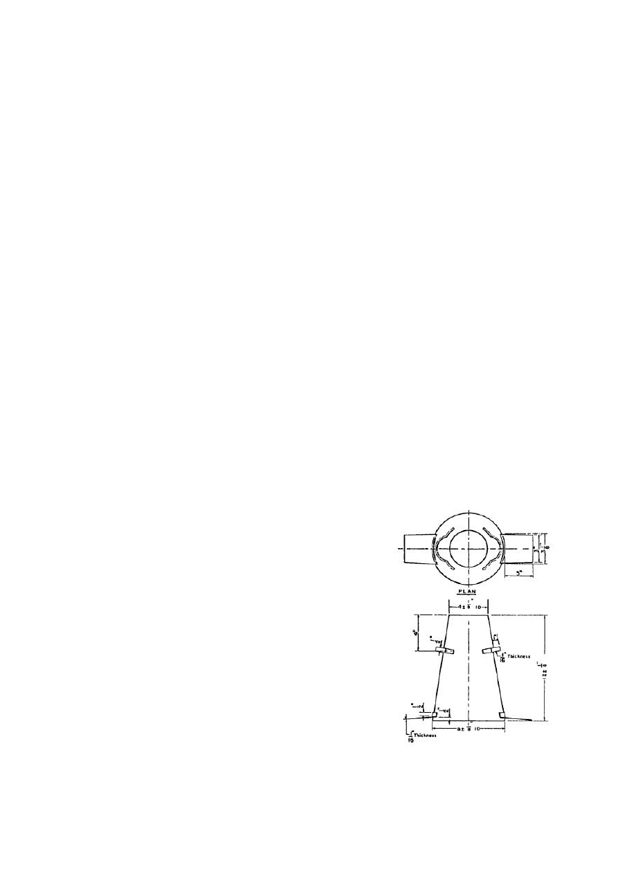
3.1 Mold—The test specimen shall be formed in a mold made of metal
not readily attacked by the cement paste. The metal shall not be thinner
than 0.060 in. [1.5 mm]. The mold shall be in the form of the lateral
surface of the frustum of a cone with the base 8 in. [200 mm] in diameter,
the top 4 in. [100 mm] in diameter, and the height 12 in. [300 mm]. The
base and the top shall be open and parallel to each other as shown in
Fig.1. The interior of the mold shall be relatively smooth and free from
deformation or adhered mortar.
3.2 Compacting rod.
3.3 Nonabsorbent base plate.
3.4 Tape measure.
3.5 Scoop.
Fig. 1 Mold for Slump Test

42
4. Procedure
4.1 Dampen the mold and place it on a flat, moist, nonabsorbent (rigid)
surface.
From the sample of concrete immediately fill the mold in three
layers, each approximately one third the volume of the mold.
4.2 Rod each layer with 25 strokes of the tamping rod. Uniformly
distribute the strokes over the cross section of each layer. For the bottom
layer this will necessary inclining the rod slightly, and then progressing
with vertical strokes spirally toward the center. Rod the second layer and
the top layer each throughout its depth,
so that the strokes just penetrate
into the underlying layer.
4.3 In filling and rodding the top layer, heap the concrete above the mold
before rodding is started. If the rodding operation results in subsidence of
the concrete below the top edge of the mold, add additional concrete to
keep an excess ofconcrete above the top of the mold at all times. After the
top layer has been rodded, strike off the surface of the concrete by rolling
motion of the tamping rod.
4.4
Remove the mold immediately from the concrete by raising it
carefully in a vertical direction. Raise the mold a distance of 12 in. [300
mm] in 5 ± 2 s by a steady upward lift with no lateral or torsional motion.
Complete the test from the start of the filling through removal of the mold
without interruption and complete it within an elapsed time of 2.5 min.
4.5 Immediately measure the slump by determining the vertical difference
between the top of the mold and the displaced original center of the top
surface of the specimen.