Electronic Circuits I Laboratory
10
2 DIODE CLIPPING and CLAMPING CIRCUITS
2.1 Objectives
• Understanding the operating principle of diode clipping circuit
• Understanding the operating principle of clamping circuit
• Understanding the waveform change of diode clipping and clamping circuits
when the bias is applied.
2.2 Basic Description
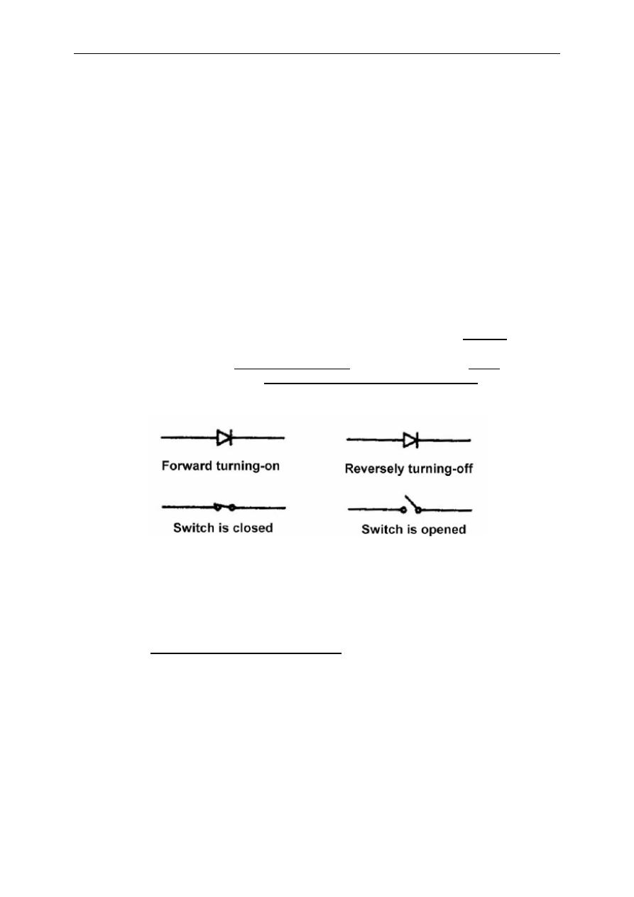
As you know, diodes can be used as switches depending on the biasing type,
reverse of forward. The clipping circuit, also referred to as clipper, clips off some of
the portions of the input signal and uses the clipped signal as the output signal. The
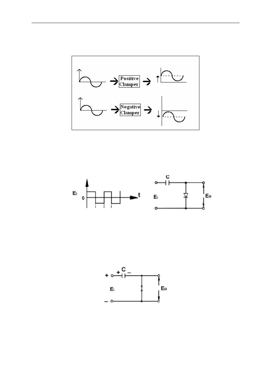
clamping circuit or clamper keeps the amplitude of the output signal same as that of
the input signal except that the D.C. level (offset) has been changed. The clamper
through which the input waveform shifts to positive direction is called positive
clamper, otherwise, is called negative clamper.
Fig. 2.1 – Ideal Diode – Switch Terminalogy
2.2.a Clipper Circuits
There are two types of clipper circuits, the series and parallel diode clipping
circuits.
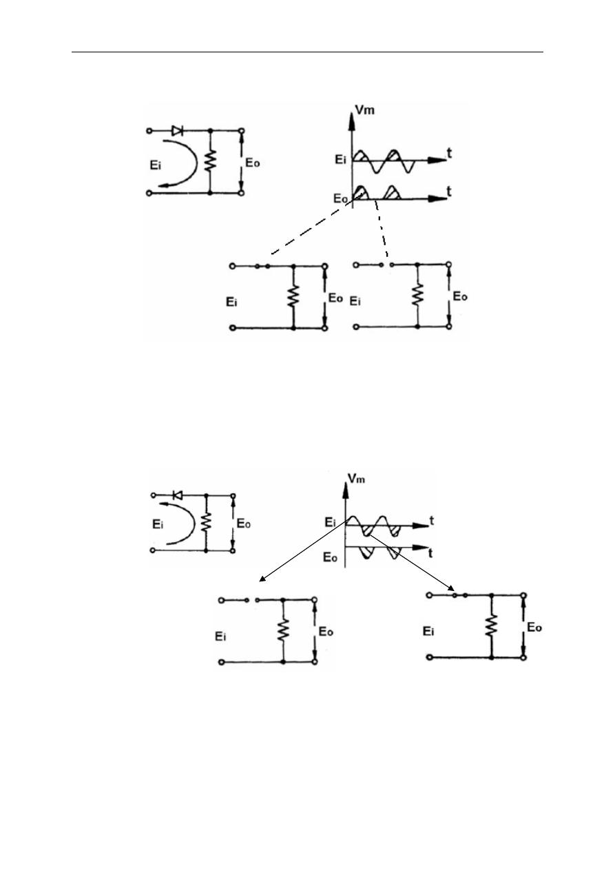
2.2.a.1 Series Diode Clipping Circuit
In these type of circuits, the diode is connected between the input and output
voltage terminals (Fig 2.2)
Electronic Circuits I Laboratory
11
Fig. 2.2
As Fig.2.2 reveals, the negative cycle of the input voltage can be clipped of by
this type of series clippers. Reverse of the diode pins yields to a positive cycle
clipping circuit as shown in Fig. 2.3.
Fig. 2.3
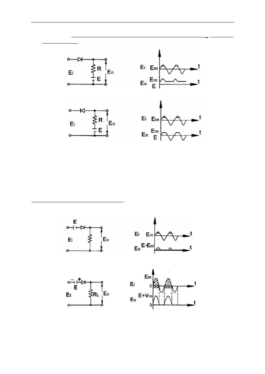
Previous circuits clip the values larger or smaller than zero voltage. This
voltage, technically called “threshold voltage” and can be changed to a desired value
by inserting a D.C. voltage source. This is achieved in two different ways.
In the first type, the voltage source of E
m
( positive or negative) is connected
through output terminals as in Fig. 2.4. Depending on the diode connection (normal
Electronic Circuits I Laboratory
12
or reverse), the values smaller (Fig.2.4.a) or greater (Fig.2.4.b) than E
m
is clipped
and assigned as E
m
. .
a
b
Fig. 2.4.
Note that if E
m
is negative, ( where the voltage source is reversely connected)
again the values smaller or larger than this negative value is clipped, do not get
confused.
In the second type of thresholded series clipping, the voltage source is
applied between the input and output terminals, series with the diode. This time, the
clipped values are assigned to zero and the net output voltage equals to the
difference between the input and threshold values.(If E
m
is negative, then E
0
= E – E
m
= E + |E
m
|
)
a
b
Fig. 2.5
Electronic Circuits I Laboratory
13
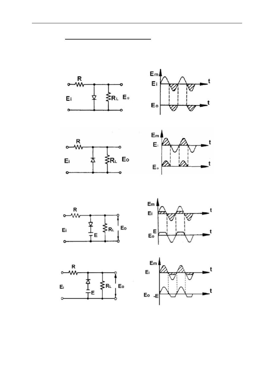
2.2.a.2 Parallel Diode Clipping Circuit
In this type of clippers, the diode is connected between output terminals. The
on/off state of diode directly affects the output voltage. These type of clippers may
also have a non-zero threshold voltage by addition of a voltage series with diode.
Following figures illustrate the clipping process.
a
b
Fig. 2.6 – Zero Threshold Parallel Clippers
a
b
Fig. 2.7 – Thresholded Parallel Clippers
Electronic Circuits I Laboratory
14
2.2.b Clamper Circuits
Clamper Circuits, or briefly clampers are used to change the D.C. level of a
signal to a desired value.( Fig 2.8 ).
Fig 2.8
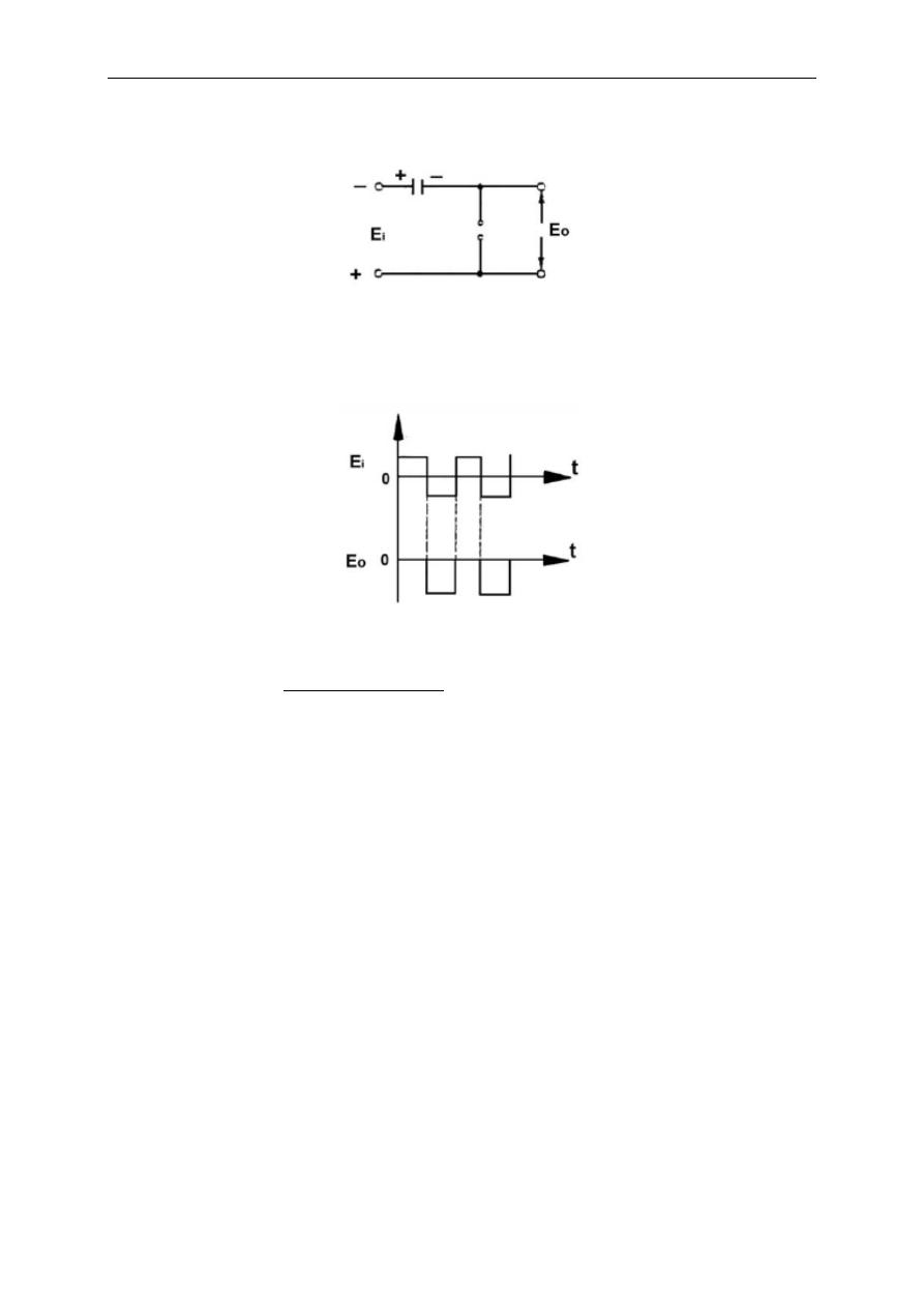
Being different from clippers, clamping circuits uses a capacitor and a diode
connection. When diode is in its on state, the output voltage equals to diode drop
voltage (ideally zero) plus the voltage source, if any. Now let us examine the
clamping process for the circuit in Fig. 2.9
.
Fig 2.9 – Typical Clamping Circuit
As you know, this circuit, in fact, is a series R-C circuit. The resistance of diode
( several ohms above its drop voltage) and the small capacitance yield to a small
time-constant for this circuit. This means that the capacitor will rapidly be charged if
any input voltage, that is enough to swtich on the diode, is applied. The diode will
conduct during the positive cycle of the input signal (Fig. 2.10) and output voltage will
be ideally zero ( in practice this voltage equals ~0.6 V).
Fig 2.10. Diode conducts during positive cycle
Note that during positive cycle the capacitor is rapidly charged in inverse
polarity with the input voltage. After transition to negative cycle, the diode becomes to
its off state. In this case, the output voltage equals to the sum of the input voltage
and the voltage across the terminals of the capacitor which have the same polarity
with each other.(Fig 2.11)
Electronic Circuits I Laboratory
15
E
0
= - ( |E
i
|+ |E
c
| )
Fig. 2.11. Diode is switched off during negative cycle
The resulting signal after a complete cycle is shown below.
Fig. 2.12
By this process, the input signal is shifted to negative D.C. value (its maximum
value is ideally zero) without any change in its amplitude ideally.
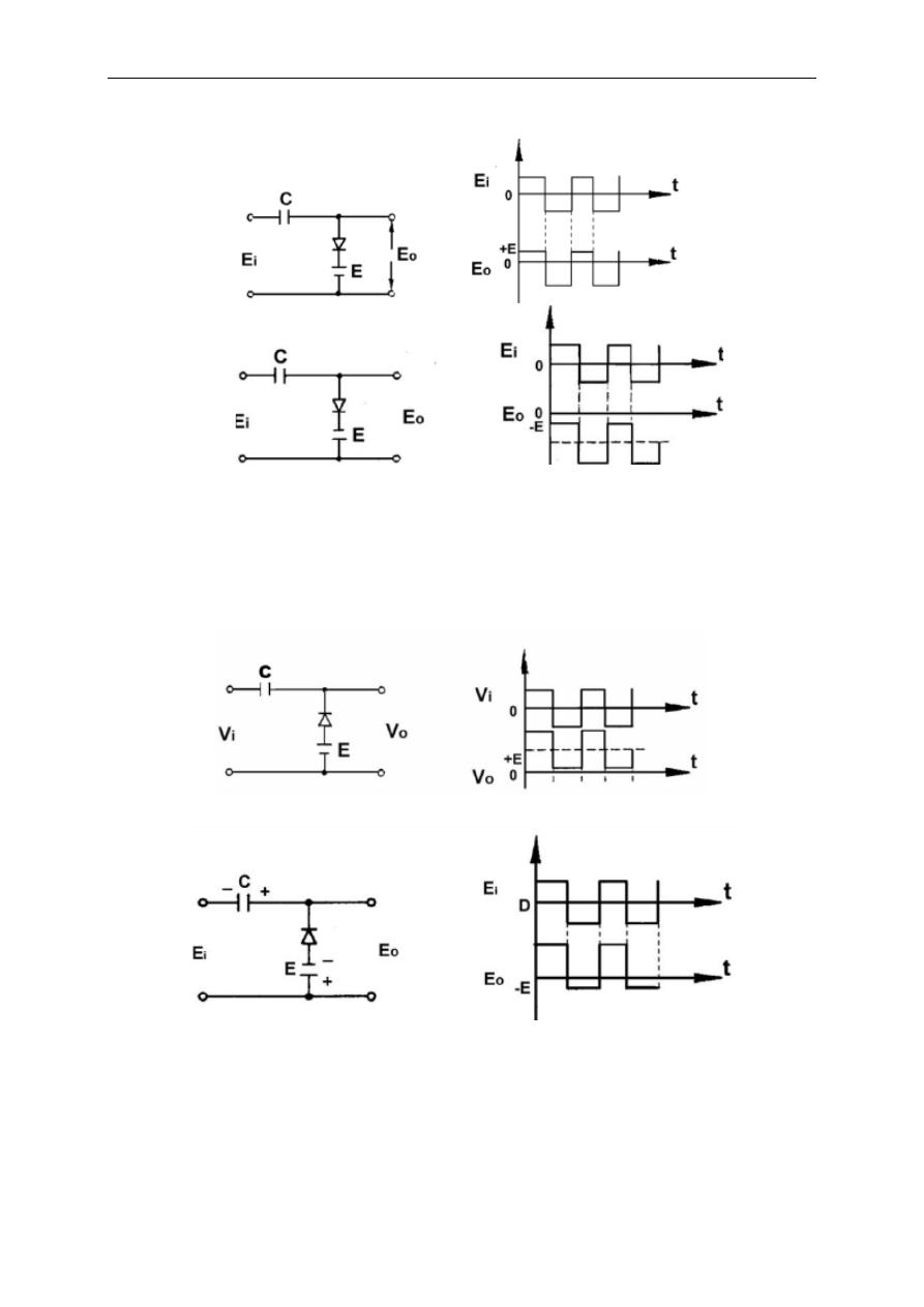
There exist again modified versions of this circuit inwhich a threshold value is
inserted for clamping. Following figures illustrate these modifications and resulting
outputs.
Electronic Circuits I Laboratory
16
Fig.2.13
Fig. 2.14
Fig 4
Procedures:-
Procedure 1: Series Diode Clipping Circuit
1- Connect the circuit as shown in Fig.1
2- Adjust function generator to 5V p-p 1KHz sinewave that will be used during whole experiment
3- Use oscilloscope to have clear view of input and output signals.
4- Record the plot output voltage on graph.
5- Repeat steps for circuit in Fig.2.
Procedure 2: Parallel Diode Clipping Circuit
1- Arrange short circuit clips referring to Fig.3.
2- Record the plot of output voltage on Graph.
3- Repeat steps above for the circuit in Fig.4.
Fig 1
Fig 2
Fig 3
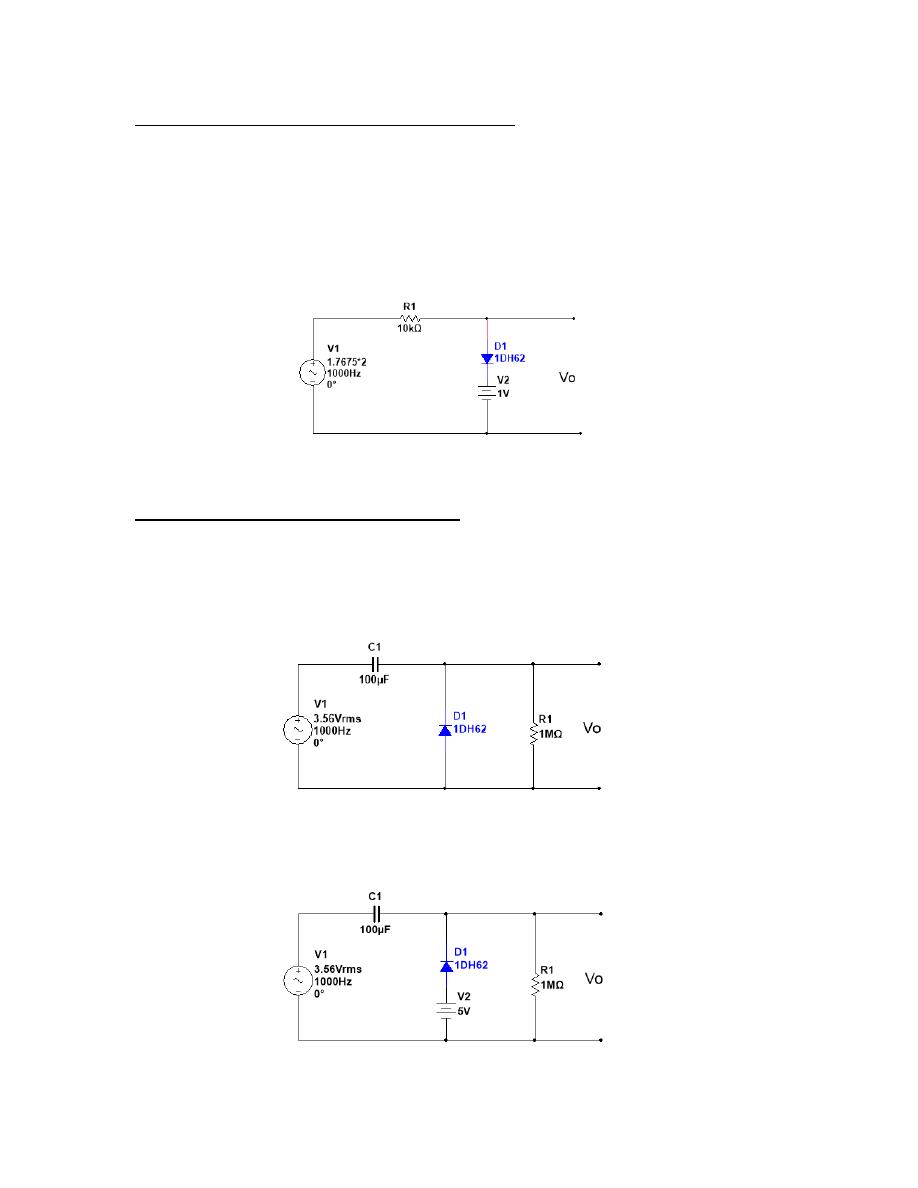
Procedure 3: Thresholder Parallel Diode Clipping Circuit
In this procedure, a threshold value is added to the previous circuit layout.
This is achieved by substitution of lower short-circuit clip with a voltage source.
1-
Turn off all active devices, and connect short-circuit clip and voltage source (+ 1 V DC) by
referring to Fig.5.
2- Record the plot of output voltage on Graph.
Procedure 4 : Diode Clamping Circuit:
1- Connect the circuit shown in Fig.6.
2- Record the plot of output voltage on Graph.
3- Repeat steps above for the circuit in Fig.7.
Fig 5
Fig 6
Fig 7
Conclusion:-
Discussion:
1- What is clipper circuit, for what it could be used?
2- What is clamper circuit, for what it could be used?
3- What is the advantage of the capacitor in clamper circuit?
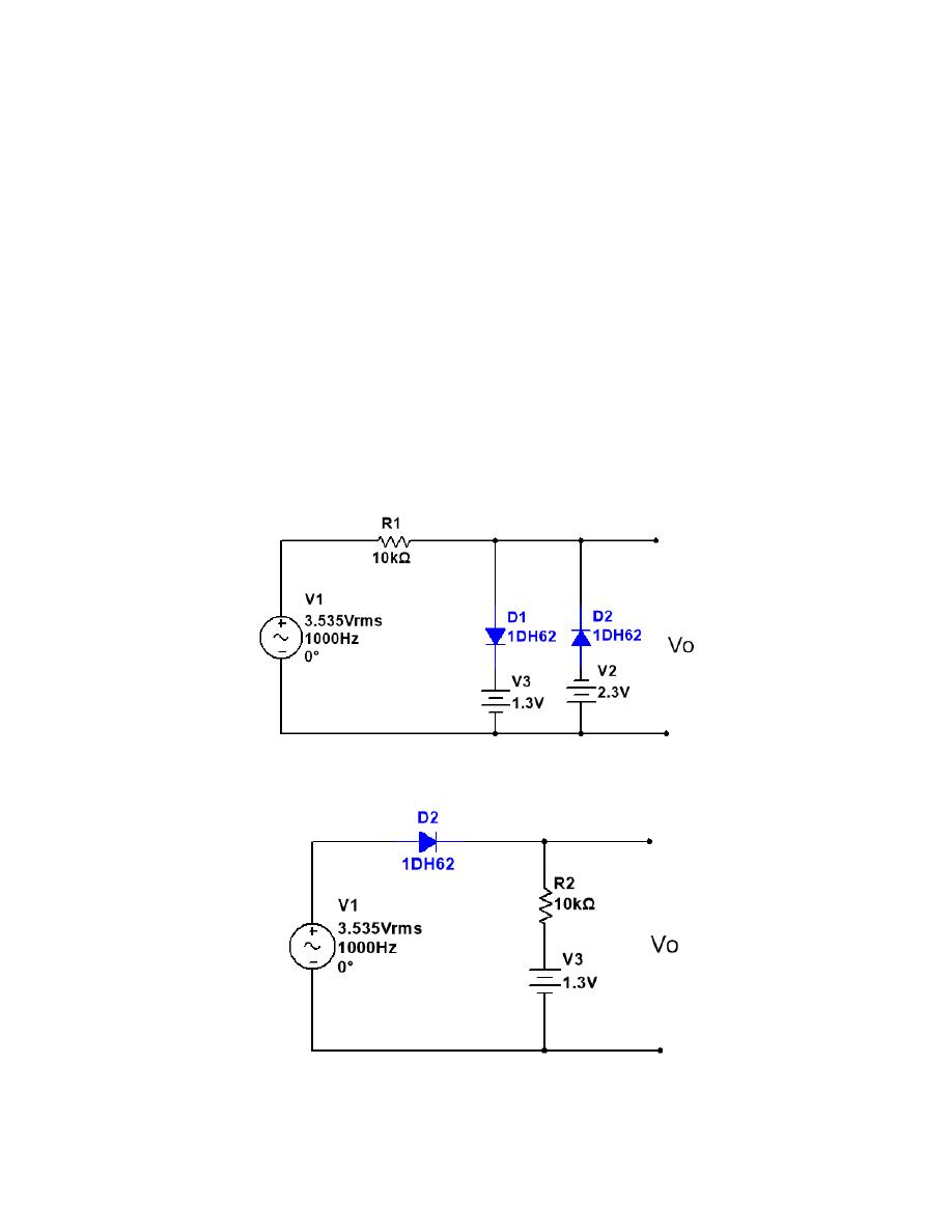
4- Guess and plot the output voltage for circuits below:
Fig 8
Fig 9